

Page 1
7. CERTIFICATION 8. SPECIFICATIONS 8. SPECIFICATIONS 9. ACCESSORIES AND SPARE PARTS
Technical Services
EMEAI:
US:
AP:
Asia Pacific
Honeywell Analytics Asia Pacific
#701 Kolon Science Valley (1)
43 Digital-Ro 34-Gil, Guro-Gu
Seoul 152-729
Korea
Tel: +82 (0)2 6909 0300
Fax: +82 (0)2 2025 0328
analytics.ap@honeywell.com
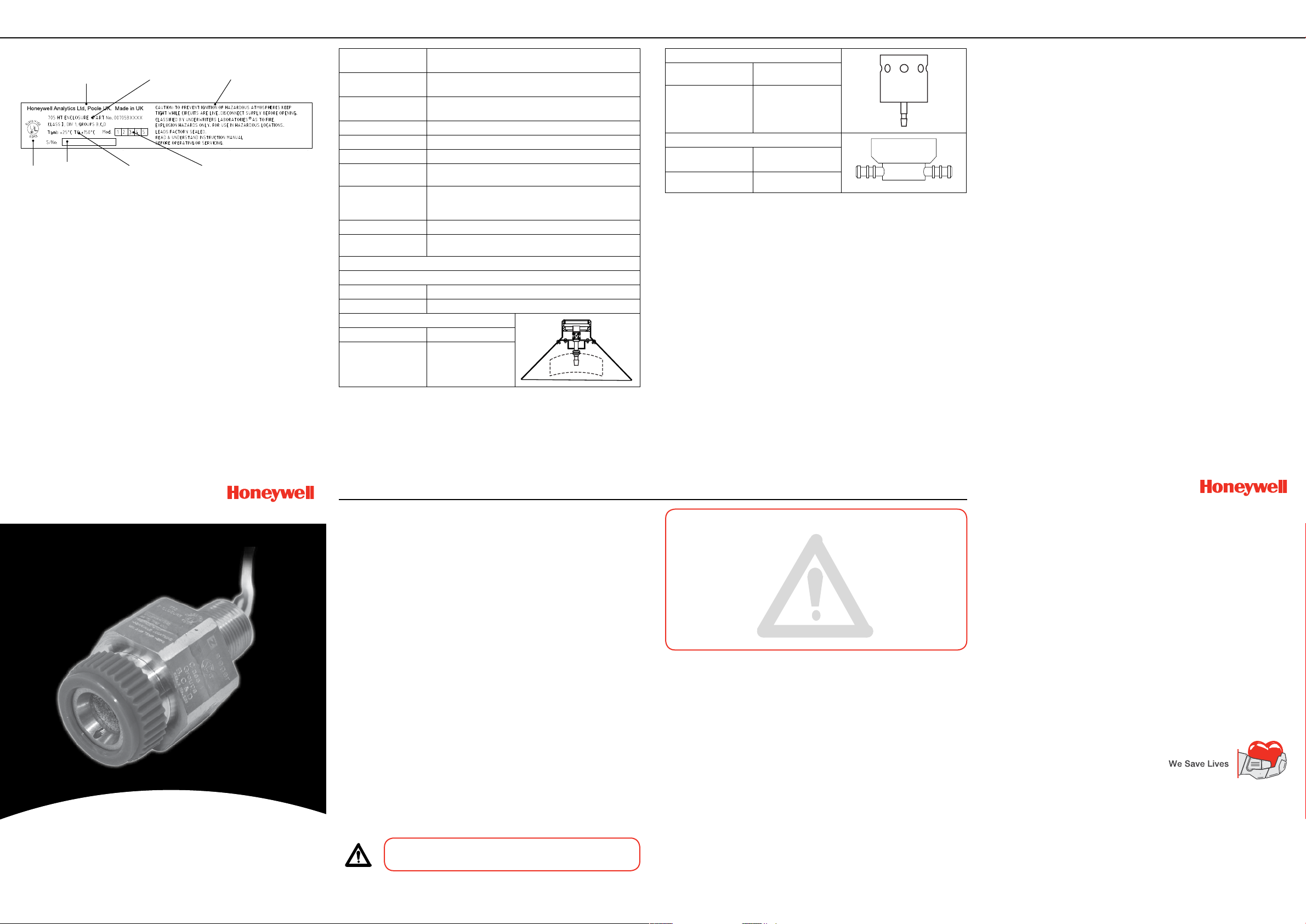
The following UL certication information is imprinted on the sensor body.
Manufacturer’s Trademark,
Name and Address
UL Control Number
Serial Number
Product Name
and Part Number
Certied Ambient
Temperature Range
Cautions
Modication
Status
Operating
temperature range
Storage temperature
range
Operating humidity
range
Drive current 200mA +/- 2mA (from control equipment)
Power consumption 0.7W
Calibration ow rate Recommended 1.5 l/min +/- 0.1 l/min
Response time T60 - less than 6 sec.
Temperature
coefcient of
zero point
Line resistance Refer to control system documentation
UL Certication Class I, Div 1, Groups B, C, D
Dimensions and weights
Sensor
Dimensions 78mm x 55mm (51mm or 47.2mm across ats)
Weight 200g
Collecting Cone
Dimensions 87mm x 165mm dia.
Weight 175g
-25°C to +150°C
-25°C to +150°C
20% to 90% RH continuous - non condensing
10% to 100% RH intermittent -non-condensing
T90 - less than 10 sec.
o
Approximately 0.05% LEL Methane per
Tamb -25
o
C to +150oC
C (maximum)
Weather Protection Housing
Dimensions 76.5mm x 50.8mm
Weight 52.4g
Sample Flow Housing
Dimensions 61mm x 45mm x
Weight 110g
dia.
31mm
When ordering accessories and parts, always quote the complete part number.
Where a component part number is not listed or known, state type, material, cable
entry size and other relevant details.
Complete replacement 705 HT sensor (Part No: 00705-A-1735)
Identify the gas to be detected when ordering a complete replacement sensor.
Collecting Cone (Part No: 00780-A-0032)
Used for the detection of lighter than air gases. A lter must be tted. A nozzle on
the cone (6.5mm O.D.) permits gassing of the Sensor with the cone in position.
Test gas is applied either direct to the nozzle or via a permanently connected
pipe-line when the sensor is in an inaccessible location.
Weather Protection Housing (Part No: 00780-A-0076)
This accessory, tted to a sensor installed in an exposed location, protects the
sensor from driving rain from vertical to 30° below horizontal. When mounted close
to the ground, it protects from heavy rain rebounding off the ground. It also reduces
contamination from industrial waste and enables the application of test gas in high
wind speeds without signicant error.
Incorporated in the housing is a nozzle to facilitate gassing of the sensor with the
housing in position, either by direct application to the nozzle or via a permanently
connected pipeline. The nozzle is free to rotate within the housing to allow removal
from the sensor without disconnecting a permanently connected pipeline, when
changing the lter and cleaning the sensor.
Sample Flow Housing (Part No: 00780-A-0035)
This accessory allows sampling of a closed system by means of two pipes.
The housing is tted to the sensor accessory thread by a locking ring that enables
the housing to be removed without disconnecting the pipeline. The lter is retained
by the housing and interfaces with a gasket bonded to the housing
(Part No: 00780-A-0048).
Stainless Steel Filter (Part No: 00780-F-0018)
Two layers of stainless steel mesh in the form of a disc with a rubber rim to provide
mechanical protection of the sinter and exclude large dust particles.
Quick Start Guide
Type 705 High Temperature
Combustible Gas Sensor
11 12 13
1. INTRODUCTION
The 705 High Temperature (HT) Combustible Gas Sensor is a gas detector that is
UL certied for Class I, Division 1, Groups B, C and D for installation in a hazardous
area.
It employs a catalytic pellistor sensor device which is used as part of a bridge
measuring circuit. The sensor must be mounted on a suitably UL approved hightemperature junctionbox in the hazardous area and connected to control equipment
situated in a non-hazardous area to form part of a combustible-gas detection system.
The sensor comprises an aluminium housing containing a pair of poison resistant
detector elements, with a sintered stainless steel disc forming the face of the
sensor. The sensor contains two elements which are heated by a supply derived
from the associated control equipment. One element is sensitive to the presence
of combustible gas, the element temperature increasing in response to catalytic
oxidation of the gas. The resultant rise in resistance of the sensitive element,
proportional to gas concentration, is processed by the associated control module.
The non-sensitive element compensates for effects of changes in ambient
temperature. The sensor drive current is set to a value appropriate to the type of
elements used.
The housing has a 51mm or 47.2mm AF body with a 3/4 NPT mounting thread at one
end and an M36 accessory thread on the other end. The following accessories are
available for use with the sensor (also see Accessories & Spare Parts):
• Collecting Cone
• Weather Protection Housing
• Sample Flow Housing
• Hydrophobic Barrier
• Gassing Point Assembly
When delivered a disposable plastic Filter Housing with protective disc for the sinter
is tted to the M36 accessory thread.
Note: The protective disc should not be removed until after the sensor is installed.
Refer to Installation for different Honeywell Analytics System 57 components to
which the 705 Sensor can be connected and to the associated control system
documentation for external wiring and connection information.
If information outside the scope of these instructions is required please contact
Honeywell Analytics. The types of information notices used throughout this document
are as follows:
WARNING
Indicates hazardous or unsafe practice which could result in severe
injury or death to personnel.
Caution: Indicates hazardous or unsafe practice which could result in minor injury to
personnel, or product or property damage.
Note: Provides useful/helpful/additional information.
1. This apparatus is not suitable for use in oxygen enriched atmospheres
(>21%V/V). Oxygen decient atmospheres (<10%V/V) may suppress sensor
output.
2. Refer to local or national regulations relative to installation at the site.
3. Operators should be fully aware of the action to be taken if the gas
concentration exceeds the alarm level.
4. Atmospheres above 100% LEL may suppress the sensor reading.
5. The catalytic detector element is resistant to catalyst poisons, however,
abnormally high concentrations of halogenated hydrocarbons, vapours of
heavy metals or compounds, some silicone compounds and sulphur
compounds may cause loss of sensitivity.
1. Do not modify or alter the sensor construction as essential safety requirements
may be invalidated.
2. Install using suitably approved and certied high temperature junction box,
connectors and glands.
3. Installation should consider not only the best placing for gas leakage related to
potential leak points, gas characteristics and ventilation, but also where the
potential of mechanical damage is minimized or avoided.
4. The sintered disc on the sensor assembly must be kept free from
contaminants, e.g. oil and dirt.
5. The Code of Practice covering Selection, installation, use and maintenance
of detectors for ammable gases and oxygen, IEC 60079-29-2, should be
complied with at all times. Refer to the appropriate local/national regulations
relative to the installation site.
7. Dispose of in accordance with local/national disposal regulations.
Materials used - Stainless Steel.
2. SAFETY
WARNINGS
CAUTIONS
1 2
Find out more
www.honeywellanalytics.com
Contact Honeywell Analytics:
Europe, Middle East, Africa, India
Life Safety Distribution AG
Javastrasse 2
8604 Hegnau
Switzerland
Tel: +41 (0)44 943 4300
Fax: +41 (0)44 943 4398
India Tel: +91 124 4752700
gasdetection@honeywell.com
Americas
Honeywell Analytics Inc.
405 Barclay Blvd.
Lincolnshire, IL 60069
USA
Tel: +1 847 955 8200
Toll free: +1 800 538 0363
Fax: +1 847 955 8210
detectgas@honeywell.com
HAexpert@honeywell.com
ha.us.service@honeywell.com
ha.ap.service@honeywell.com
www.honeywell.com
14
Please Note:
While every effort has been made to ensure accuracy in this
publication, no responsibility can be accepted for errors or
omissions. Data may change, as well as legislation, and you are
strongly advised to obtain copies of the most recently issued
regulations, standards, and guidelines. This publication is not
intended to form the basis of a contract.
Issue 2 09/2013
H_MAN0625_EMEAI
00705M5010_ECO A04169
© 2013 Honeywell Analytics
Page 2
3. INSTALLATION
3. INSTALLATION
3. INSTALLATION 3. INSTALLATION
The 705 HT sensor must be tted into a suitable UL approved high temperature
junction box tted with an approved cable gland for external wiring. The sensor
requires a 200mA current supply, nominal 3V, derived from a suitable control card.
Only a qualied installation engineer should install the sensor.
Install the sensor in a location free from direct heat sources and t it so that it either
points downwards or horizontally. It is not recommended that the sensor points
upwards.
1. Isolate all associated power supplies and ensure that they remain OFF during the
installation procedure. Ensure a gas free atmosphere.
2. Install a suitably approved UL high temperature junction box.
See the manufacturer’s instructions. The box provides a mounting point for
the sensor.
3. Remove the junction box lid.
4. Fit the 705 HT sensor to the junction box.
Ensure that the junction box thread and the sensor thread are compatible.
The mounting threads should be coated with an approved anti-seize compound,
such as a light petroleum grease.
Push the sensor wires through the cable entry in the junction box and screw the
sensor body rmly home into the entry. To comply with certication requirements,
a minimum of ve threads must be engaged.
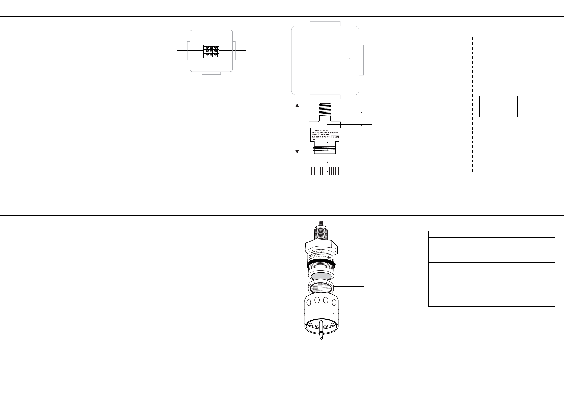
5. Connect the sensor wiring to the junction box terminal strip.
See the subsequent wiring diagram. Use multicore cable, three wire minimum,
of conductor size 2.5mm2 (14AWG) max.
6. Fit a suitable gland/conduit to the box, secure the control system cable and
connect the cable wiring to the terminal strip.
7. Ret the junction box lid.
8. Unscrew the lter housing from the sensor body and remove the lter from the
lter housing.
Discard the lter housing with protective disc. The lter housing material cannot
withstand high temperatures. Keep the lter.
Sensor wiring Control system
Brown Sensitive (S)
Blue
White
10. If required, t an accessory to the sensor.
See subsequent instructions. In a clean atmosphere, and where no accessories
are to be tted, a lter is not needed.
11. Power-up the system, calibrate the sensor (if required), and check for correct
operation of the gas detector.
Fitting the Weather Housing and Collecting Cone Accessories
1. Fit the previously removed lter to the accessory.
The lter must be tted to these accessories.
2. Firmly screw the accessory to the body of the sensor.
Note: When tting a lter, keep it free from oil and dirt and other contaminants.
Fitting the Flow Housing Accessory
1. Ensure the gasket (Part No: 00780-C-0048) is tted to the Flow Housing.
2. Apply a thin coating of anti-seize compound, such as a light petroleum grease, to
the sensor accessory thread.
3. Firmly screw the accessory to the body of the sensor.
Note: When tting a lter, keep it free from oil and dirt and other contaminants.
Suitably approved UL
HT Junction Box
eld wiring
Non-Sensitive (NS)
Common - Linked (01)
82.5mm
Suitably Approved
UL High Temperature
Junction Box
3/4 NPT thread
51mm or 47.2mm
across ats
Certication data
705 HT Combustible
Gas Sensor 0-100%LEL
M36 thread
for accessories
Filter (only used
with accessories)
Filter Housing (discard not suitable for high
temperature operation)
Sensor installation with System 57 components
NON-HAZARDOUS AREA
SYSTEM 57
COMPONENTS
CONTROL
CARDS
05700-A-0311
05700-A-0313
05700-A-0321
05700-A-0323
05700-A-0401
TO
05700-A-0409
05700-A-3000
INTERFACE
CARDS
05700-A-0950
05700-A-0951
05700-A-0952
05700-A-0953
INTERFACE
MODULES
05700-A-0201
05700-A-0202
05700-A-0211
05700-A-0212
05700-A-0221
05700-A-0231
SUITABLY
APPROVED UL
CERTIFIED
JUNCTION BOX
705 HT SENSOR
00705-A-1735
3
4. CALIBRATION
Sensors should be calibrated at concentrations representative of those to be
measured. It is always recommended that 705 HT is calibrated with the target gas
it is to detect. Gassing is carried out at the sensor and adjustments are made at
the control card.
5.1 No accessories tted
Where there are no accessories tted to the sensor, it is recommended that the
Sample Flow Housing accessory is used when gassing the sensor (see 5.3).
Where this is not possible, a suitable plastic bag may be used.
Caution: Calibration should only be attempted by qualied service personnel.
5.2 Collecting Cone or Weather Protection Housing Fitted
1. Using rubber tubing, connect the test gas to the gassing nozzle or to the
permanently connected tubing if tted to the accessory.
Cautions:
1. Spring pressure on the gassing nozzle of the Weather Protection Housing
accessory forces the nozzle against the sinter. Rotation of the nozzle may
damage the sinter if a lter is not tted.
2. Direct gassing of the sensor via the nozzle on the Collecting Cone accessory in
wind speeds greater than 5m/s may cause errors.
2. Set the ow rate to 1.5 ± 0.1 litres per minute and test the system in
accordance with the instructions in the relevant system equipment manual.
3. On completion, shut off the test gas and disconnect the rubber tubing.
5.3 Sample Flow Housing Fitted
1. Shut off the sample ow to the Flow Housing.
2. Disconnect the input pipeline from the input nozzle of the Flow Housing.
3. Using rubber tubing, connect the test gas to the Flow Housing input nozzle.
4. Set the ow rate to 1.5 ± 0.1 litres per minute and test the system in
accordance with the instructions in the relevant system equipment manual.
5. On completion, shut off the test gas and disconnect the rubber tubing.
6. Reconnect the input pipeline to the Flow Housing input nozzle and restore the
sample ow.
4 5
5. MAINTENANCE
Only a qualied installation engineer should service the sensor. Ensure power is off
before carrying out any maintenance procedures.
Maintenance consists of cleaning the sensor and accessories and replacing the lter.
Both these can be carried out without removing the sensor from the junction box.
Sensor and accessories may be cleaned using an industrial grade of Methanol,
providing the appropriate safety precautions are taken when handling this solvent.
Whenever cleaning takes place, a new lter must be tted.
To change a lter carry out the following procedure:
1. Remove the accessory (if tted) from the sensor.
2. Remove the old lter and replace with a fresh lter.
3. Replace the accessory (if tted).
Ensure any seals are retted/correctly located. The diagram shows the sensor with
the Weather Protection accessory tted.
5. MAINTENANCE
Sensor body
Weather Protection Seal
Filter
Weather Protection
6
6. FAULT FINDING
The following table provides a list of possible faults related to the sensor together
with possible causes and remedies.
Fault Cause/Remedy
Sensor reads non-zero all the time Gas could be present, ensure
Sensor reads non-zero when no gas is
present
Sensor reads low when gas is applied Adjust the control system span setting
Sensor reads high when gas is applied Adjust the control system span setting
Sensor reads zero when gas is applied 1. Check the wiring
In the event of exposure to contaminant, e.g. silicones or silicone based products,
or prolonged exposure to high concentration of gas, the sensor should be operated
for 24 hours in a clean environment and then recalibrated.
If the sensor is found to be faulty, or cannot be calibrated, the complete sensor
must be discarded and replaced.
there is no combustible gas in the
atmosphere
Adjust the control system zero setting
2. Check that the protective disc has
been removed from the lter housing
3. Check that the lter is not dirty/
obstructed
4. Replace the sensor if poisoning is
suspected
7
8 9
10
 Loading...