

Page 1
Put Bar Code Here
Honeywell Model 700/800 Signal
Contents
Application ....................................................................... 1
Features ........................................................................... 1
Specifications ................................................................... 2
Approvals ......................................................................... 3
Installation ........................................................................ 3
Operation ......................................................................... 10
Modbus Communication .................................................. 14
Troubleshooting ................................................................ 17
Maintenance .................................................................... 17
Safety Manual: 700 Signal Processor .............................. 33
Safety Manual: S70X & 80X Viewing Head ..................... 36
Processor and Viewing Head
USER MANUAL
• Model 700ACSP Universal 85-265 VAC powered, plus
24VDC backup.
• Model 700DCSP 22-26VDC powered, plus 24VDC
backup.
The two Model 700 signal processors are similar, with 12
push-buttons, a two-digit numeric display, and four LED status
indicators for operator interface. The only difference between
the two is that one accepts AC power and the other accepts
DC power. Both models also accept 24VDC backup power.
Most of the signal processor connections are made through
Phoenix plug-in connectors. Communication connections are
made through modular phone jacks located at the top of the
signal processors (Fig. 8).
Both signal processor models mount on a standard 35 mm
DIN rail. They snap into place and may be released from the
rail using a flat screwdriver.
APPLICATION
The Honeywell Model 700ACSP and Model 700DCSP signal
processors are single-channel, fail safe, flame monitoring
systems when used In conjunction with the S70X/S80X
viewing heads. They offer easy setup, excellent discrimination,
and high reliability.
FEATURES
Viewing heads are interchangeable between the two signal
processor models. Any viewing head in the two families will
work with any of the signal processors.
Two signal processor models are available:
There are two types of viewing heads—IR/flicker-sensitive and
UV-sensitive—with various features offered resulting in ten
different models. See Table 1 on page 2 for details.
The S702 and S706 viewing head housings are larger in
diameter than the S80X series, are made of aluminum, and
are secured with over-center latches to their mounting blocks
(Fig. 9). In contrast, the S802 and S806 viewing head
housings are smaller in diameter and are made of stainless
steel (Fig. 10). An 800 series viewing head is secured in its
mounting block by a friction twist-lock.
The IR/flicker sensitive viewing heads have a high-pass filter
that passes flicker frequencies above 33 Hz. Some models
have a built-in high pass filter that only passes frequencies
above 155 Hz. The high frequency filter models are identified
by adding “HF” to the model number. The UV models respond
to the level of UV radiation—not UV flicker—so there is no
filter option.
66-2069-02
Page 2

HONEYWELL MODEL 700/800 SIGNAL PROCESSOR AND VIEWING HEAD
Table 1. Available viewing head models and associated features.
Pipe Fit Connection
0.5 in. NPTM with 50-ft
Model Connector
S702 X X X
S702HF X X X X
S702PF X X X
S702HFPF X X X X
S706 X X X
S706PF X X X
S802 X X X
S802HF X X X X
S806 X X X
1. All models include Electronic self-check.
2. Flicker Frequency filter settings available for IR sensor
models.
3. Gain Selection available through Signal Processor.
The viewing heads, the viewing head connector, and the cable
provided are watertight, and have NEMA 4X ratings when the
connector is properly tightened with pliers and the cable is
protected from UV exposure.
The availability of both UV-sensing and IR/flicker-sensing
viewing heads ensures that the flame monitoring systems can
provide good discrimination in most single and some multiple
burners firing a single fuel. UV sensing is appropriate for
monitoring natural gas, some mixed gases and light oil flames.
IR/ flicker sensing is appropriate for monitoring heavy oil and
coal flames.
(15.2 m) pigtail
UVTron
Sensor IR Sensor
UV Detector Spec
S706 & S706PF, S806: UVtron with spectral response 185nm
to 260nm and a peak response at 210nm
UV Optical
Angle of View: 5 degrees (1 inch per foot)
Cable & Connectors - S70X/S80X Viewing Heads
New installations - highest level of EMI shielding available:
ASY785 --> 50 foot C330S cable with pre-wired ASY786
connector.
ASY785-200 --> 200 foot C330S cable with pre-wired
ASY786 connector.
ASY786 --> Field wireable connector with shield.
Dimensions
Refer to Fig. 9 and Fig. 10.
High
Frequency
Filter 155Hz
Aluminum
Housing
Stainless Steel
Housing
Model 700ACSP & Model 700DCSP Signal
SPECIFICATIONS
Series 700 and 800 Viewing Heads
MODELS S702, S702PF, S702HF, S702HFPF, S706,
S706PF, AND MODELS S802, S802HF, AND S806
Electrical
24VDC Power is supplied by Signal Processor
Environmental
Viewing Head Sealing: NEMA TYPE 4X rated when the
molded connector ring is tightened with pliers and a UV
protection is provided for the cable by installing in conduit.
Ambient Temperature: -40°F to 185°F (-40°C to 85°C)
IR Detector Spec
S702, S702PF, S702HF, S702HFPF, S802, S802HF:
Germanium photodiode with spectral response 950nm to
1710nm (1/2 intensity points) and peak spectral response
at 1400nm
High Pass Filter Pickup: 33 Hz standard, 155 Hz high
frequency option (-HF)
IR Optical
Angle of View: 1 degree (1.45 in. dia. at 6 ft. or 3.7 cm dia. at
1.8 m)
Processer
Electrical: Model 700ACSP
Primary Input Power: 85-265VAC, 50-60 HZ, 0.07A Max.
fused (with either V.H. connected)
Battery Backup Voltage: 22VDC to 26VDC, 0.2A DC Max.
fused (with either V.H. connected)
Electrical: Model 700DCSP
Primary Input Power: 22VDC to 26VDC, 250 mA Max. fused
(with either V.H. connected)
Battery Backup Voltage: 22VDC to 26VDC, 0.5A DC Max.,
fused (with either V.H. connected)
Outputs
Flame Relay: 2 form C contacts
Self-Checking Relay: 1 form C contact
Relay Contact Ratings: 5A at 125 VAC, 277 VAC, & 30 VDC;
1/8 HP 125 & 250 VAC
Analog Flame Signal: Isolated 0 to 20 mA or 4 to 20 mA
output for remote meters or DCS, 360 ohms maximum
resistance
Environmental
Ambient Temperature: 32°F to 140°F (0°C to 60°C)
Dimensions
Refer to Fig. 11 and Fig. 12.
66-2069—02 2
Page 3

HONEYWELL MODEL 700/800 SIGNAL PROCESSOR AND VIEWING HEAD
WARNING
APPROVALS
S70X/S80X Viewing Heads (Connector series and Pipe fit
series [PF])
CSA for CLASS I, DIV 2, GROUPS A, B, C, D & T4A
FM 7610/NEMA 4X and CLASS 1, DIV 2, GROUPS A, B, C, D
& T4A*
SIL 3 “Fit for Use”
IECEx CSA 10.0003 Ex nA IIC T4 Gc
-40<Ta<85ºC, -40<TA<185ºF
*IP67/NEMA 4/4X rating applies when connector ring is
properly tightened and cable is UV shielded
700ACSP and 700DCSP Signal Processors
CSA (C, US)
FM
INSTALLATION
When Installing These Products...
1. Read these instructions carefully. Failure to follow them
could damage the products or cause a hazardous
condition.
2. Check the ratings given in the instructions and one the
products to make sure the products are suitable for your
application.
3. Installer must be a trained, experienced, flame
safeguard control technician.
4. After installation is complete, check out product
operation as provided in these instructions.
Signal Processor Mounting
The 700ACSP and 700DCSP signal processors mount on a
standard 35mm DIN rail. They snap into place and may be
released from the rail using a flat screwdriver.
Grounding and Shielding
NOTE: Installer must be a trained, experienced flame
safeguard service technician and should be
familiar with the equipment operation and
limitations and be aware of any applicable local
codes and regulations.
1. Connect a safety ground to the viewing head housing (if
applicable). A ground screw is provided on the exterior
of the viewing head housing for this purpose.
The viewing head housing is grounded through
cable/signal processor, so you must ensure that
AC/DC potentials at ground of signal processor
and viewing head are the same, or damage to the
cable or signal processor can result.
2. The viewing head and all associated cable/conduit must
be at least 12 inches (31 cm) from any source of high
energy or voltage (for example, igniter equipment).
3. Install a ground wire from the ignition transformer case
to the igniter assembly.
4. Ensure all igniter wires and cables show no signs of
wear. Replace any igniter cables or wires that are frayed
or cracked.
5. The viewing head must be electrically isolated from the
burner front.
a. Electrical isolation can be accomplished by
installing an Ultem nipple (R-518-13) or an Ultem
locking coupler adapter (R-518-PT13 or R-518PT13L) in conjunction with a locking coupler (R-518CL13-HTG) between the viewing head flange and
the burner mount.
b. The purge air line should also be isolated from the
viewing head. This can be accomplished by
installing any insulating material, for example a
rubber hose, in between the purge air line and the
viewing head.
Signal Processor Power Connections
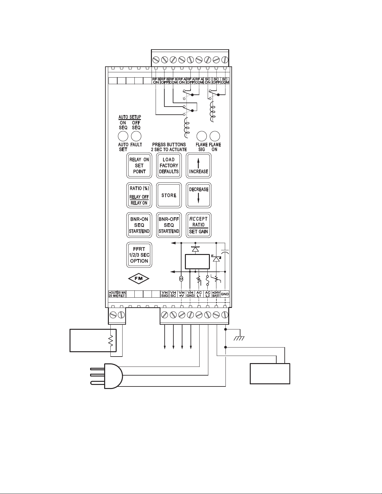
The Model 700ACSP power and relay connections are shown
in Fig. 1. The AC power supply to the 700ACSP Signal
Processor passes through a 2A fuse and an inrush current
limiter.
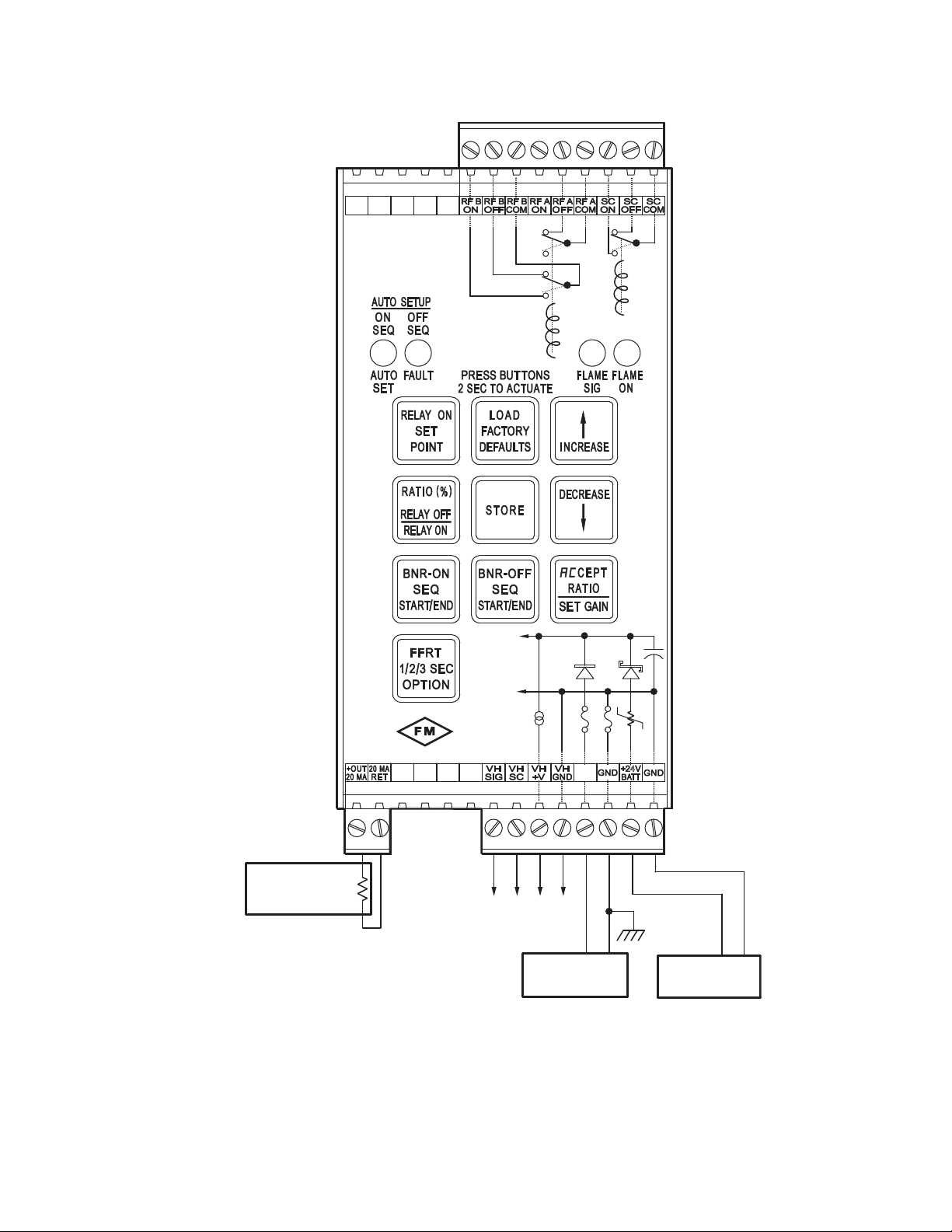
The Model 700DCSP power and relay connections are shown
in Fig. 2. The maximum current requirement for each
700DCSP is 250mA.
In the Model 700 signal processors the flame relay (RF A/B
ON, OFF, COM) has two sets of FORM C (SPDT) contacts
and the self-check relay (SC ON, OFF, COM) has one set (Fig.
1 and Fig. 2). The self-check relay is energized whenever the
signal processor is powered and is operating normally,
whether the flame relay is energized or not. Internally, the
flame relay is wired in series with the self-check relay (not
shown), which prevents the flame relay from energizing if the
self-check relay is not energized.
Unique fail-safe circuitry for the self-check and flame relays
ensure that in the event of any critical component failure
occurrence, system response will be to de-energize the selfcheck relay, which in turn de-energizes the flame relay.
Some of the internal power wiring of the Model 700ACSP and
Model 700DCSP signal processors is shown in Fig. 1 and
Fig. 2. Rectifier diodes separate the battery backup input from
the main power bus until the battery voltage exceeds the
internal DC voltage plus a diode voltage drop. Resettable
fuses (shown as resistors with slashes) and conventional
fuses prevent internal failures from loading the power sources.
With the Model 700DCSP, if a backup battery is to be used
with a main power supply, the two power sources would be
wired as shown in Fig. 2. If no backup battery is to be
installed, the main power supply can be connected at +26V
PWR and GND as shown in Fig. 2 or it can be connected to
the +24V BATT input and GND. It is preferable to use the
battery connections because it takes advantage of the
resettable fuse at the battery input; resettable fuses recover
automatically from a fault within a few seconds after power is
removed. At the +26V PWR input and its associated GND,
conventional1A fuses are used because they are able to
protect against 240VAC being applied by accident (this could
happen if a Model 700DCSP is installed in a cabinet wired for
a Model 700ACSP).
3 66-2069—02
Page 4
HONEYWELL MODEL 700/800 SIGNAL PROCESSOR AND VIEWING HEAD
APPROVED
AC IN
GROUND
TO VIEWING
HEAD
24 V
BACKUP BATTERY
(OPTIONAL)
0-20 OR 4-20 MA
FOR INDICATOR OR
INSTRUMENTATION
360 OHMS MAX
+
-
+
-
CHASSIS,
EARTH, OR
SYSTEM GND
M34280
+
+26VDC
GND
.125 A
.4A
2
A
AC POWER
SUPPLY
-t°
Fig. 1. Model 700ACSP Signal Processor Wiring.
66-2069—02 4
Page 5
HONEYWELL MODEL 700/800 SIGNAL PROCESSOR AND VIEWING HEAD
+
+26VDC
GND
.4A1A 1A
.125 A
LIM
M34282
APPROVED
24 V
BACKUP BATTERY
(OPTIONAL)
+
-
0-20 OR 4-20 MA
FOR INDICATOR OR
INSTRUMENTATION
360 OHMS MAX
+
-
CHASSIS,
EARTH, OR
SYSTEM GND
DC POWER SUPPLY
250 MA
+
-
+26
PWR
TO VIEWING
HEAD
Fig. 2. Model 700DCSP Signal Processor Wiring.
5 66-2069—02
Page 6
HONEYWELL MODEL 700/800 SIGNAL PROCESSOR AND VIEWING HEAD
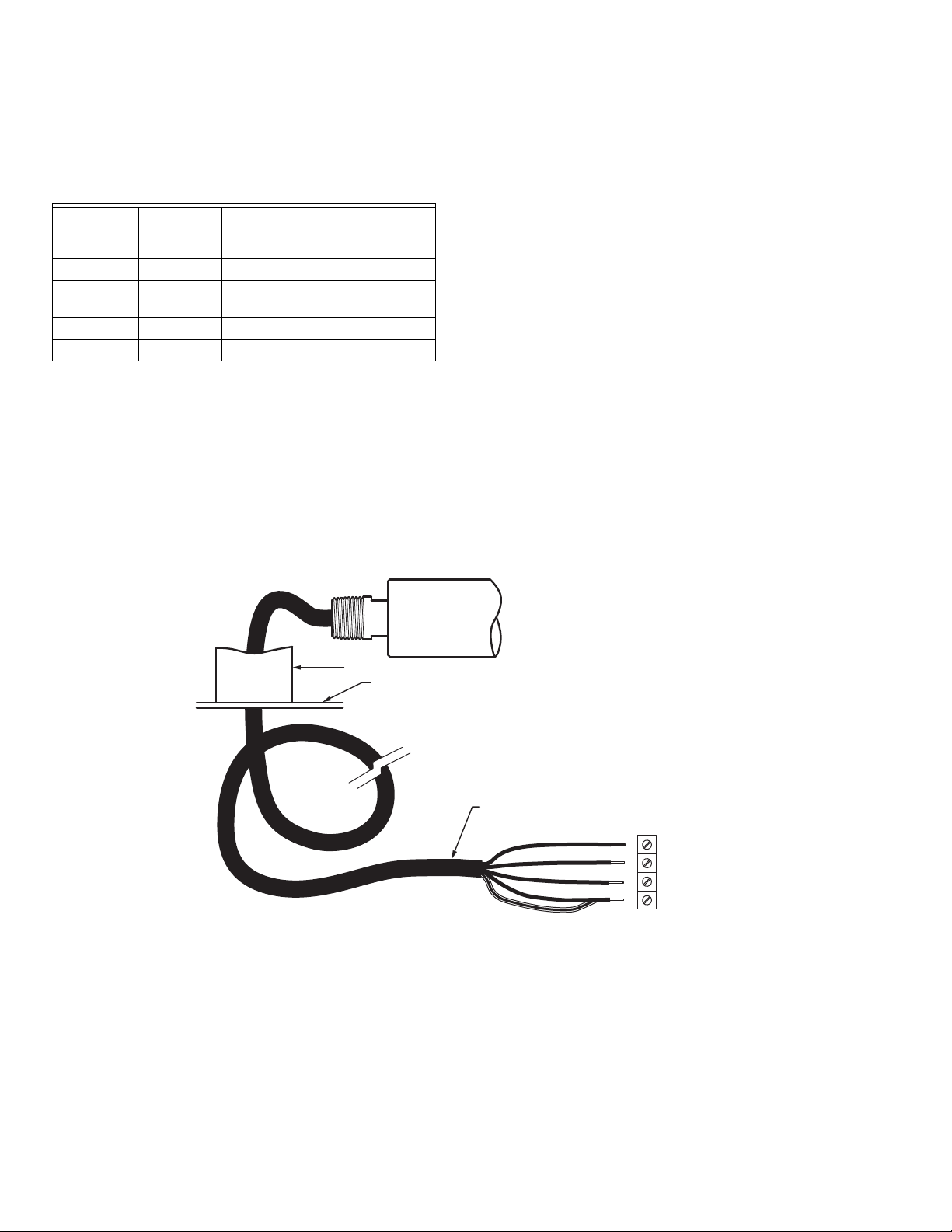
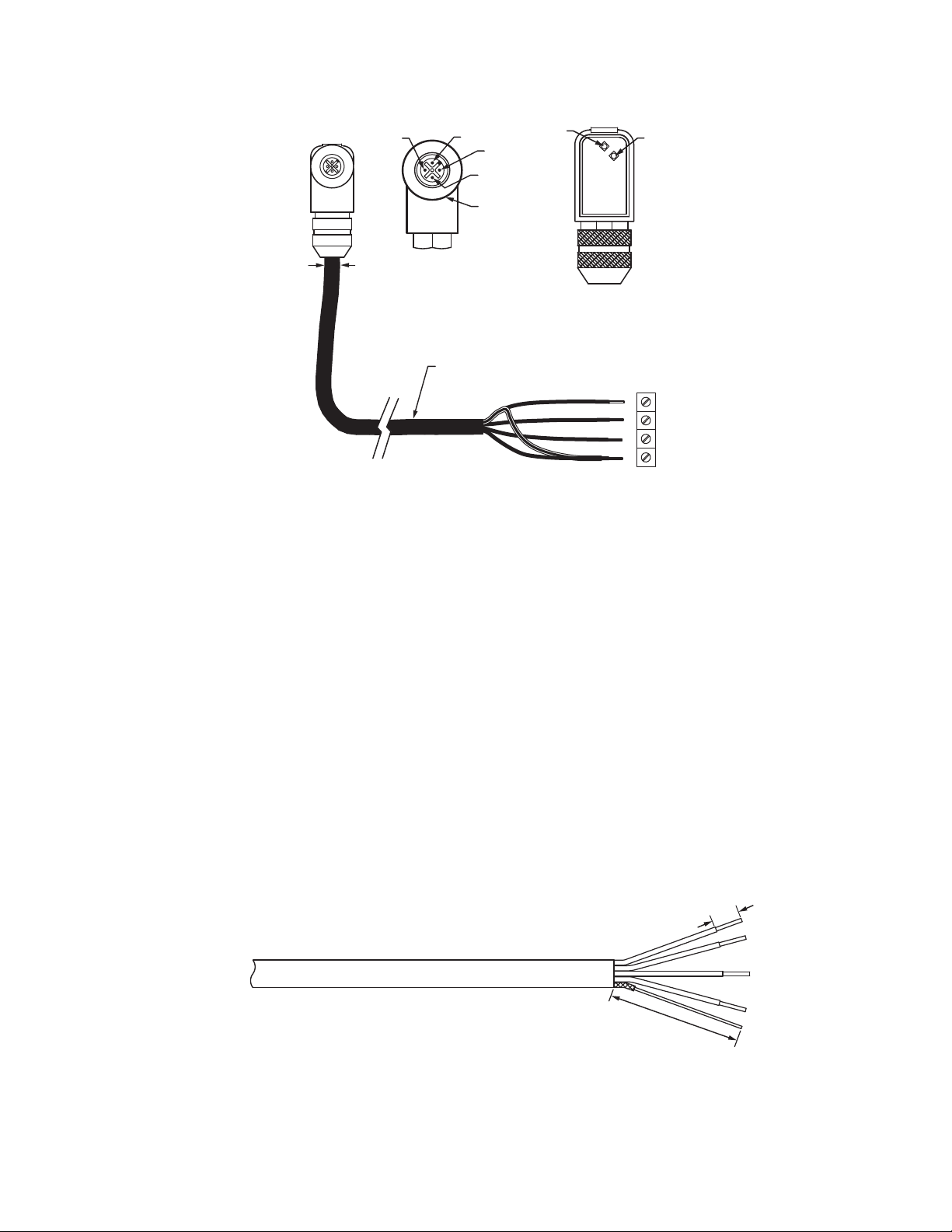
WHITE
BLACK
RED
GREEN
TERMINAL
VH SIG
VH SC
VH +V
VH GND
CONDUIT
ENCLOSURE
S702PF, S702HFPF OR S706PF
SHIELD
C330S YELLOW 4-CONDUCTOR
WITH DRAIN AND SHIELD
STANDARD "PIGTAIL" LENGTH = 10 FEET (3 METERS)
M34285B
Viewing Head Connector and Wiring
Viewing heads are wired to the appropriate terminals located
on bottom of the 700ACSP, 700DCSP, P531 or P532 signal
processors. The terminals are listed functionally in Table 2.
Table 2. Terminal Descriptions.
700ACSP or
700DCSP
Ter minal
P531 or
P532
Terminal
VH SIG VH3 SIG Flame Signal from Viewing Head
VH SC VH3 SC Shutter Drive Signal to Viewing
Head
VH +V VH3 +V +24VDC Power to Viewing Head
VH GND VH3 GND GND Signal Ground
Connectors and cables are shown in Fig. 3, Fig. 4, and Fig. 5.
Fig. 3 shows the viewing head cable with the 1/2 in. NPT pipe
fitting and pigtail for use in a conduit. The PF model comes
with 50 feet of Honeywell C330S cable. This cable is
recommended for all new installations. It has ITC and CIC
ratings for hazardous location. Figs. 4 and 5 describe the
C330S cable used with the right angle field-wireable
connector. Refer to “Accessories” on page 9 for part numbers.
The customer may also supply his own cable; a replacement
mating viewing head connector should be ordered. Refer to
Description
“Accessories” on page 9 for part numbers. The use of 22g, 4conductor cable with shield and drain is recommended. The
shield should be foil and braid type surrounding all
conductors. The shield should be connected to GND at the
processor end. The cable diameter should not exceed 0.307"
in order for it to go through the hex bushing in the connector.
But note that wiring the cable to the connector is not easy
because of the limited space. Also, the LED indicator
assembly must be mounted inside the connector and,
preferably, soldered in place. Thus, it is recommended to
purchase a pre-wired cable and connector assembly from
Honeywell.
NOTE: FOR CLASS I, DIV 2 RATING, CABLING IN
HAZARDOUS LOCATIONS MUST COMPLY WITH
NEC ARTICLE 500 REQUIREMENTS AND
APPLICABLE GOVERNING CODES.
In the U.S., cables should have UL’s ITC rating; in Canada,
cables should have CSA’s CIC rating. The recommended
C330S cable has both ratings.
NOTE: To obtain a NEMA 4X seal between the connector
and the viewing head, tighten the metal
connector ring securely.
Fig. 3. Model 700 Viewing Head Cable With 1/2 in. NPT Fitting.
66-2069—02 6
Page 7
HONEYWELL MODEL 700/800 SIGNAL PROCESSOR AND VIEWING HEAD
NOTE: IMPORTANT INSULATE DRAIN WITH SHRINK TUBING LEAVING 3/8" STICKING OUT.
M35139
STRIP 3/8 INCH TYPICAL
1-19/64 (33)
TYPICAL
VH SC
5-16 (8)
MAX
VIEWING HEAD
CONNECTOR
LOOKING AT PINS
VH SIG
C330S YELLOW, 4 COND
WITH FOIL/BRAID SHIELD
AND DRAIN (ITC & CIC)
Fig. 4. Model 700/800 Viewing Head Cable Connections.
Cable Preparation
NOTE: This section will typically be used for reference
only. The S70X/S80X connector parts are very
small and delicate and difficult to assemble. It is
advisable to purchase pre-made cables from
Honeywell.
GREEN
LED
VH +V
VH GND
METAL
CONNECTOR
RING
2. Pull braided and foil shield back so that only drain wire
3. Insulate the drain wire with heat shrink.
4. Strip other wires as shown in Fig. 5.
ORANGE
LED
CONNECTOR REAR VIEW
WITH NUT LOOSENED
AND COVER REMOVED
WHITE
BLACK
RED
SHIELD
GREEN
TERMINAL
VH SIG
VH SC
VH +V
VH GND
M34286A
is at 2 inch length. Trim the foil and braid shields at the
cable jacket.
Honeywell C330S cable is recommended for use with the
S70X/S80X viewing heads and signal processors. C330S has
a UL ITC rating and can be used in the U.S. in hazardous
locations.
NOTE: Shield shrink tubing is required on shield drain
wire at the signal processor end.
Preparation of the C330S cable at the signal processor should
be done as follows:
1. Referring to Fig. 5, strip cable 2 inches back to expose
the braided shield.
Fig. 5. C330S Signal Processor End Cable Preparation.
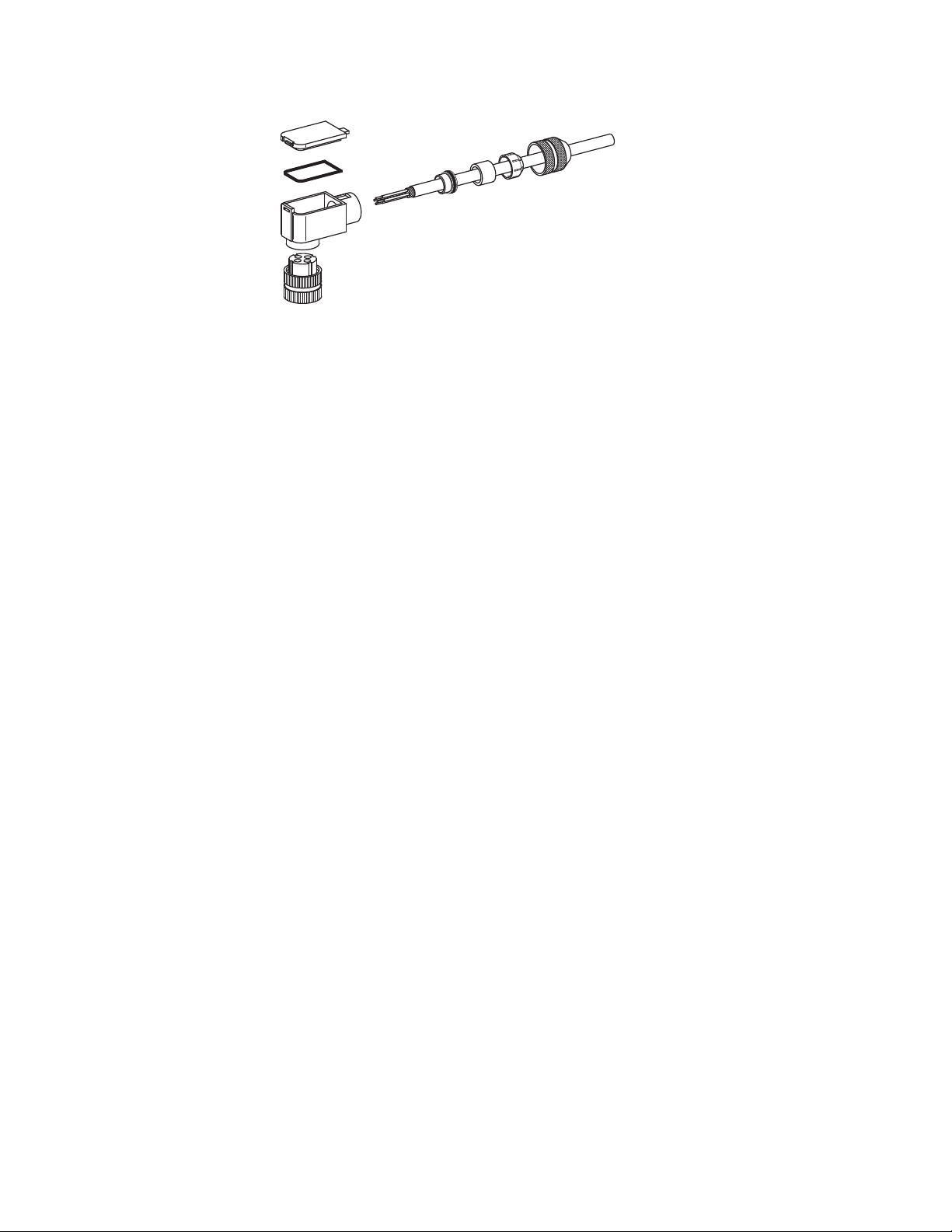
Connection of the Honeywell type C330 cable to the viewing
head plug is shown in Fig. 6. Cable preparation should be
done as follows:
1. Prepare C330S wire at plug end similarly to Fig. 5, but
shorten the drain/shield to approximately 1/4 inch only
at the plug end (see Fig. 6).
2. Assemble the field-wireable plug as shown in Fig. 6.
Ensure that:
a. Wires are in proper locations per Fig. 4.
b. Shield is pressed against connector housing.
c. Connector back plate gasket is in place before
installation.
d. After assembly, check that connector is tight and
well secured.
7 66-2069—02
Page 8
HONEYWELL MODEL 700/800 SIGNAL PROCESSOR AND VIEWING HEAD
Fig. 6. ASSY786 Viewing Head Plug Assembly with C330S.
M35140
Protecting the Viewing Head Cable (Connector Series)
Note that when the wiring needs to meet Class I, Division 2
requirements for use in hazardous locations and when conduit
is used, the conduit must be sealed where the cable passes
from the hazardous location to the non-hazardous location in
order to keep potentially hazardous gases from being
conducted into the non-hazardous area.
Viewing Head Connector LED Indicators
The viewing head connector has orange and green LEDs
which can be viewed from the rear of the connector when the
connector cover is removed.
The green LED displays the pulses out of the viewing head
and the orange LED shows that the self-checking signal from
the signal processor is reaching the viewing head. If power is
on at the signal processor, the orange LED should flash at one
pulse per second, even if the viewing head is not plugged in.
This is helpful in troubleshooting.
With no flame signal present, the green LED will flash one
pulse per second in step with the self-checking signal. The
viewing head is sending back an ID pulse; this is part of the
self-checking system. When a flame is present, the green
LED will flash at a rate proportional to the flame signal, except
when the pulses are interrupted once per second for the selfcheck pulse arrival at the viewing head. The pulse rate of the
green LED flashes can be used for aiming the viewing head.
NOTE: The LED indicators are provided for alignment
and troubleshooting only. Reinstall cover with
gasket correctly in place at all times, and ensure
that connector coupling is tightened securely.
This gasket and cover must be installed properly
to maintain NEMA rating.
Viewing Head Mounting and Sighting
Mounting is 1/2-in. NPT (F) for all viewing head models with a
1/4-in. NPT (F) purge air connection. Before beginning
installation, determine the best location for mounting the
viewing head based upon the following factors:
Viewing Head Mounting Block
The S70X viewing heads are held firmly in place in their
mounting blocks by two galvanized steel latches. The S80X
viewing head is secured in its mounting block by a friction
twist-lock. Refer to the ACCESSORIES section for part
numbers.
Pressure
The S70X viewing head lens will withstand 50 psi (3.4 bar)
while the S80X lens will withstand 90 psi (6.2 bar), provided
the compression ring on the purge air adapter is tightened
properly. If the lens assembly is exposed to greater pressures
through the sight pipe, then an isolation unit must be used.
Honeywell isolation units with purge air entrance are available
as accessories; ISO-UNIT, ISO-UNITSS, ISO-UNITHPGT.
Each has a quartz window, two 1-in. NPTF connections and a
1/2-in. NPTF purge port.
Temperature
The case temperature of the viewing head housing must not
exceed 185°F (85°C) while the standard Delrin mounting
block must not exceed 180°F (82°C) continuous service. Care
should be taken to ensure the case housing and mounting
block temperatures do not exceed these values.
Purge air will help reduce conducted heat through the sight
pipe and flange. A heat insulating Ultem replacement viewing
head mounting block is available for both the S70X/S80X
models (part numbers 700UA and 800UA) with a continuous
service rating of 320°F (160°C) as well a 1/2-in. NPTM Ultem
nipple (part number R-518-13) or an Ultem locking coupler
adapter (R-518-PT13 or R-518-PT13L) to reduce the
conducted heat, but direct radiation can cause the housing
case temperature to exceed limits. If the ambient heat (direct
radiation) is excessive, then an air cooling canister with vortex
cooler should be considered or alternately a fiber optic
extension. The extension uses a fiber optic cable assembly
between the sight pipe and the viewing head, allowing the
viewing head to be placed further away from the heat source.
Refer to the Fiber Optic Manual 69-2683 or contact your
distributor or the factory for assistance with fiber optic
selection and pricing.
Purge Air
Use a flexible air supply line, to allow for repositioning of the
viewing head and sight pipe until a final and permanent
66-2069—02 8
Page 9

HONEYWELL MODEL 700/800 SIGNAL PROCESSOR AND VIEWING HEAD
position has been decided. A continuous flow of air must be
maintained in order to reduce the conducted heat and to keep
the sight pipe and viewing head lens free of dirt and debris. Air
required is about 5 SCFM (0.13 Nm3 /min) delivered at 1 in.
(25mm) above the maximum pressure as measured at the “Y”
or “T” section of the purge air connection for each viewing
head. The air supply must be clean, free of oils and water, and
preferably cool. In order to electrically isolate the viewing
head, the purge air line should be installed using an insulating
material, such as a rubber hose, in between the purge air line
and the viewing head.
Vibration
Do not install the viewing head where it could be subject to
high vibration. Provide an anti-vibration mount if excessive
vibrations are present.
Clearance
Make sure there will be sufficient room to remove the viewing
head housing for servicing.
Viewing Head Mounting
Honeywell offers a range of swivel mounts, both pipe thread or
flange mounting for use with sight pipes or direct wind box
mounting. See “Accessories” on page 9 or the Honeywell
website for further details.
Viewing Head Sighting
The sighting of the viewing head should be parallel to the
center line of the burner in the direction of the flame. If used,
the sight pipe should be mounted as close to the center line
as possible so as to sight along the flame rather than across
the flame. Doing so will ensure continuous flame detection
under changing load conditions. See Fig. 15, 16 and 17.
Utilizing a sighting or the sight pipe aimed at the root of the
flame (where the turbulent combustion air mixes with the
flame) is a good starting point for optimizing the sighting.
Where practical, using a swivel mount to “zero-in” on the
highest signal will assure maximum performance. The
optimum scanner location is parallel to the burner center line.
The use of a swivel mount allows for line of sight adjustment,
where practical to use.
Examples of viewing head installation with and without a
swivel mount are shown in Fig. 13 and Fig. 14. If using a sight
pipe, its diameter should be large enough to allow a
reasonable field of view, and to allow for adjustment of the
swivel mount angle.
In some instances, it may be beneficial to use two sets of
setpoints for Flame On, Flame Off and gain. The two-channel
capability (primary and alternate viewing head settings) is
ONLY possible when using the P531 or P532 signal
processors; it is not possible when using the 700ACSP or
700DCSP signal processors. The switch-over from Channel A
to Channel B can be implemented from the burner control
system. Refer to the P531/P532 user manual, 66-2068, for
further information regarding switch-over and the use of
Channels A and B with independent settings.
ACCESSORIES
Orifice disks (kit M-702-6) - Used to reduce the signal
brightness in cases where the signal brightness is too strong.
Located immediately in front of the lens, it will reduce the
amount of signal to the sensor. Bag assembly contains orifice
disks and retaining rings. Orifice disks come with 3/8, 1/4,
3/16 and 1/8 inch diameter holes. Contact the factory for
guidance in using orifice disks.
Insulating nipple (R-518-13) - 1/2-in. NPTM Ultem heat and
electrical insulating nipple typically used in conjunction with a
swivel mount and union.
VH insulating mounting block (700UA, 800UA) - 1/2 in.
NPTF Ultem heat and electrical insulating mounting block,
used in place of the supplied Delrin mounting block. 1/4 in.
NPTF purge air connection. Typically used in conjunction with
a swivel mount. Rated for continuous service up to 320°F
(160°C).
Swivel mounts, small (700-1, 700-2, 700-3) - All have 1/2 in.
NPTM viewing head connections on one end with varying
process connections including 1 in. NPTF, 1/2 in. NPTF and
1/2 in. flanged.
Swivel mounts, large (M-701-1, M-701-2, M-701-2-FLG, M701-2-SS, M-701-3, M-701-3P, M-701-4) - All have 1 in NPTF
viewing head connections, one end with varying process
connections including 2 in. pipe slip on, 2 in. NPTF, 2 in.
flanged, 2 in. NPTF in stainless steel construction, 4.5 in.
flanged with 3 bolts, 3 in. NPTF and 2-bolt flanged.
Appropriate fittings must be used to adapt the 1/2 in. NPTF
viewing head process connections.
Insulating locking coupler adapters (R-518-PT13, R-518PT13L) - 1/2 in. NPTM Ultem adapters insulate the viewing
head electrically and thermally and are used with the R-518CL13-HTG locking couplers. The R-518-PT13L has a quartz
lens.
Locking coupler (R-518-CL13-HTG) - Used with the R-518PT13 and R-518-PT13L insulating locking coupler adapters.
Process connection end is 1/2 in. NPTF.
Connector - ASY786 --> Replacement field wireable
connector.
Cable and Connectors - S70X/S80X Viewing Heads
ASY785 --> 50 foot C330S cable with pre-wired ASY786
connector.
ASY785-200 --> 200 foot C330S cable with pre-wired ASY786
connector.
Cable (C330S) - 4-conductor with drain, foil/braided shield.
Sold per foot.
Isolation Units (ISO-UNIT, ISO-UNITSS, ISO-UNITHPGT) -
All have 1 in. NPTF connections with 1/2 in. NPTF purge ports
and quartz window. Painted aluminum or stainless steel
construction. The HPGT version has a 1/2 in. thick quartz
window for higher pressures. Appropriate fittings must be
used to adapt the 1/2 in. NPTF viewing head process
connections.
Air cooling canister (700ACC, 800ACC) - Has an air inlet
port on side. Used with vortex coolers. S80X models can be
used with the 700ACC if the 800ACC-RING adapter is used.
9 66-2069—02
Page 10

HONEYWELL MODEL 700/800 SIGNAL PROCESSOR AND VIEWING HEAD
Vortex coolers (M3204, M3208, M3210, M4025) - Used with
air cooling canister. Contact your distributor or the factory for
selection assistance.
Cable restraints (800CR, 700CRLT) - Liquid tight S80X and
S70X cable restraint versions. The 800CR includes the
700CRLT and the 800ACC-RING adapter.
S80X adapter ring (800ACC-RING) - Adapter ring to fit S80X
viewing heads to 700ACC cooling jacket and 700CRLT liquid
tight cable restraint.
Right angle adapter (700RAA) - S70X/S80X viewing head
right angle adapter. 1/2 in. NPTF to 1/2 in. NPTM connections.
Mounting blocks (700DA, 700DA-1, 800DA) - Delrin
replacement adapter/mounting blocks for S70X and S80X
viewing heads. All have 1/4 in. NPTF purge air connections.
Rated for continuous service up to 180F (82C). The 700DA
and 800DA have 1/2 in. NPTF process connections while the
700DA-1 has a 1 in. NPTF process connection. For more 1 in.
NPT accessories that can be used with the 700DA-1, refer to
the S55XB/BE manual, 66-2064.
USB to RS422/RS485 Converter (COMMOD) - Protocol
converter for use with external communication with a remote
computer.
Fiber Optic System Compatibility - The S70X and S80X
viewing heads are compatible with the Honeywell FASA fiber
optic extension products. The S700FOAD and S800FOAD
adapters are applicable, depending on the application.
Contact your distributor or the factory for assistance with fiber
optic selection and pricing.
OPERATION
IR Detector
The S702 and S802 viewing head models use a Germanium
photodiode, which responds to IR radiation/flicker in the flame.
Flame flicker is caused by the combustion, or forced air
injected in to the flame. Combustion air can be mixed with the
fuel (pulverized coal) or can be introduced separately. In either
case, forced air is introduced in such a way as to aid the
combustion process. This air is usually made turbulent by
causing it to swirl with spin vanes located in the burner throat.
Flame flicker is created when turbulent air mixes with the
flame. It is composed of random frequencies and the amount
of high frequency flicker is dependent on the fuel and the
burner.
The S702, S702PF and S802 viewing head models respond
to flicker frequencies above 33Hz while the S702HF,
S702HFPF and S802HF viewing heads respond to flicker
frequencies above 155Hz. All flicker frequencies below the
filters are ignored, so it is important to sight the viewing head
on the highly turbulent portion of the flame that contains the
higher frequencies. The location of the higher frequencies can
be predicted by examining the burner with regard to where the
turbulent air enters the flame. The optimum scanner location
is parallel to the burner center line (Fig. 15). The use of a
swivel mount is encouraged to allow for line of sight.
Filter Selection for IR Viewing Head
If a good count ratio between BNR-ON and BNR-OFF cannot
be obtained when using an IR viewing head—particularly
when monitoring oil flames—an IR viewing head with the High
Frequency (HF) filter option is recommended. The standard IR
viewing head responds to flicker frequencies above 33 Hz;
with the HF option, the IR viewing head responds to flicker
frequencies above155 Hz.
UV Detector
The S706, S706PF and S806 viewing head models use the
UVTron tube, with a spectral response of 185-260nm and
peak response of 210nm to ultraviolet radiation. The output of
the detector is a pulse stream of randomly spaced pulses
whose average rate is proportional to the UV radiation present
in the flame. The UV radiation is a direct result of the
combustion process as oxygen combines with hydrocarbons
in the fuel in the blue part of the flame. The yellow part of
flames, and the background radiation from hot refractory, do
not emit UV radiation.
The spectral range of the UV tube makes it ideal for
discriminating between flame and glowing refractory. As with
any UV radiation, it can be absorbed or masked by unburned
fuel, smoke, oil mist, dirt dust and other impurities in the fuel.
Care should be taken to select the proper viewing head for the
fuel used. Additionally, the contaminants that mask UV can be
diluted by providing a strong flow of air through the sight pipe
to clear a viewing path through the attenuating material. See
“Purge Air” on page 8.
It may also be desirable to sight the detector at an area
containing fewer masking agents such as near the burner
nozzle or near the entrance of the combustion air. Increasing
the viewing area of the detector by shortening the sight pipe or
by increasing the diameter of the sight pipe can also reduce
the attenuating effects of the masking agents.
In general, the UV viewing heads will work well on natural gas
and light oil flames. The sighting for both oil and gas flames
should be parallel to the axis of the burner and aimed at the
root of the flame, as with the IR detector. (See previous
section, “IR Detector.”) The highest UV intensity occurs near
the root of the flame (Fig. 16). In addition, the zone of higher
UV intensity does not overlap the same zones of adjacent or
opposing burner so that, with proper sighting, discrimination
can be achieved.
With low NOx gas burners, the UV radiation is usually much
less in intensity and spread out. Relatively high readings can
be obtained from all over the furnace when many burners are
in service. This is particularly true when flue gas recirculation
is used. There will however, be a relatively stronger signal
near the “root” of the flame and the more intense spot should
be located during the aiming or sighting process. This “root” or
intense spot may be further out than with the standard gas
burner so it is imperative that a swivel mount be used when
making sighting adjustments.
Another factor that needs to be considered when aiming the
viewing head is the load condition of the boiler. The flames
from a burner can be radically different at different loads. This
is one of the reasons for choosing an optimum sighting initially
that will minimize signal swing due to changing loads.
66-2069—02 10
Page 11

HONEYWELL MODEL 700/800 SIGNAL PROCESSOR AND VIEWING HEAD
Self-Checking
The self-check circuitry guards against internal component
failure. There are several tasks that require intelligent
interaction between the viewing heads and the signal
processor. If all of these interactions do not occur properly, the
viewing head will not send pulses back to the signal processor
and the flame relay will open.
Adjustment of VH Sighting and Gain
NOTE: Adjustment to the viewing head parameters
cannot be made unless the viewing head is
connected and communicating with the signal
processor.
The viewing head should be properly sighted before the
setpoints are adjusted. Adjustment can be made easier by a
1/2 in. swivel joint, which Honeywell can supply if one is not
available (refer to “Accessories” on page 9).
While the burner is firing, vary the viewing angle while
observing the green LED on the connector at the rear of the
viewing head. Adjust the viewing angle for the maximum pulse
rate, then lock the swivel joint to preserve this mechanical
setting. If the green LED pulse rate is very high or very low,
see the two paragraphs below. The locked mechanical setting
should still be correct when Model 700 viewing heads are
interchanged, because inside each Model 700 viewing head
the optical axis is aligned with the mechanical axis within ±1/4
degree. Also, the reading shouldn’t change when a viewing
head is rotated in the mount.
For the above sighting adjustments to work properly, the
flashing rate of the green LED in the connector at the rear of
the viewing head must be reasonable. On the -PF (pipe fitting)
version, there are no LEDs. The installer must observe the
flame signal on the signal processor instead.
A count rate of 16 to 20 is recommended for proper operation.
If the displayed count is above 25, the pulses begin to blur
together, making changes in the pulse rate difficult to observe.
If the displayed count is less than 8 or 10, it will be difficult to
maximize the count by adjusting the viewing head aim, since
the pulses occur too infrequently. In such a case the gain
should be increased. If the gain is set to a maximum and the
count rate persists below 8 or 10, the system can still be made
to work reliably as long as the count rate drops significantly
when the flame is removed. However, the setup should be
reviewed for proper viewing head aim and sight path to ensure
it is optimized.
Orificing
Orifice disks have been used in applications with older viewing
heads that did not have adjustable gain in order to reduce the
extreme brightness of certain burner flames. The orifice disk
kit is part number M-702-6. Orifice disks come with 3/8, 1/4, 3/
16 and 1/8 inch diameter holes. Contact the factory for
guidance is using orifice disks. The disks are installed with
retaining rings in the flange at the edge of the 1/2 inch NPT
female pipe thread for the process connection. An internal
type retaining ring is first installed by positioning a ring in the
machined groove inside the flange opening from the housing
side. The orifice disk is then inserted. Use a second retaining
ring to hold it in place so that it is sandwiched tightly between
the two retaining rings.
If the displayed flame count is 25 or higher when the gain is
set to 1, an orificing disc inserted in the back end of the
mounting block can be used. Choose a disc that gives a
reading of 12 to 24 at a low fire firing rate. The discs have a
range of orifice sizes; each size step results in about a 2:1
change in the counts displayed.
Signal Processor User Interface
The 700ACSP and 700DCSP signal processors have a user
interface that includes four lights, a two-digit display and
twelve push buttons for operation and programming. Each
button has at least one specific purpose.
To enter a menu, press and hold the applicable button for 2
seconds. Adjustments to the applicable setpoint can be made
via the INCREASE or DECREASE arrow buttons. To store the
new setting, press the STORE button until “--” is shown,
indicating the value has been accepted.
If no activity occurs for a period of four seconds while the
menu value is displayed, it will revert back to the operating
display.
To exit a menu at any time without saving changes, simply
press the RESET/rE button.
The following describes the functions of the LED indicators,
display and push buttons:
Front Panel LED Indicators and Display
• ON SEQ/AUTO SET LED (green):
— Used in conjunction with the BNR-ON SEQ START/
END and BNR-OFF SEQ START/END buttons during
the automatic setup process
• OFF SEQ/FAULT LED (green):
— Used in conjunction with the BNR-ON SEQ START/
END and BNR-OFF SEQ START/END buttons during
the automatic setup process
— Indicates a fault condition
• Two digit display
— When in operating mode, the display indicates the
current flame signal, which ranges between 00 and 29
— Upon power up, indicates whether an IR or UV viewing
head is attached and the selected gain setting; such
as r7 (IR with gain of 7) or u5 (UV with gain of 5).
— Indicates various characters during the automatic
setup process as well as whether the panel is locked
• FLAME SIG LED (yellow):
— When a flame is present, LED flashes at a rate
proportional to flame signal, except when the pulses
are interrupted once per second for viewing head selfchecks.
• FLAME ON LED (red):
— When the flame signal is above the selected value, the
LED will be illuminated and the flame relay will be
energized.
Push Button Functions
• RELAY ON SETPOINT button:
— Allows user to select flame on threshold value. When
the flame signal is above the selected value, the flame
relay will be energized. Used in conjunction with the
11 66-2069—02
Page 12

HONEYWELL MODEL 700/800 SIGNAL PROCESSOR AND VIEWING HEAD
INCREASE, DECREASE and STORE buttons (range
of 00 to 29).
• LOAD FACTORY DEFAULTS button:
— Used to restore all settings to the factory default
values
•
↑ INCREASE button:
— Used to increase parameter value when in
programming mode
• RATIO (%) RELAY OFF/RELAY ON button:
— Used along with the INCREASE, DECREASE and
STORE buttons to set the RELAY OFF setpoint at a
percentage of the RELAY ON setpoint. Adjustable
from 20% to 80%.
•STORE button:
— Stores new parameter values during programming
— After making changes “--” will be displayed indicating
•
the new values are accepted and stored
↓ DECREASE button:
— Used to decrease parameter value when in
programming mode
• BNR-ON SEQ START/END button:
— Used to initiate and proceed through the automatic
parameter setup sequence, which includes the RELAY
ON, RATIO (%) and GAIN settings (the FFRT, mA
output and communication address must be set
manually)
• BNR-OFF SEQ START/END button:
— Used during the automatic parameter setup sequence
• ACCEPT RATIO/SET GAIN button:
— Allows user to set the viewing head gain in conjunction
with the INCREASE, DECREASE and STORE buttons
— Used in conjunction with the BNR-ON SEQ START/
END and BNR-OFF SEQ START/END buttons during
the automatic setup process
• FFRT 1/2/3 SEC OPTION button:
— Used to set the FFRT timing along with the
INCREASE, DECREASE and STORE buttons
• 0-20MA 4-20MA OPTION button:
— Used in conjunction with the INCREASE, DECREASE
and STORE buttons to select the proportional mA
output for the flame signal
• RESET rE button:
— Resets a lockout condition
— Also used to exit a menu while programming
— Used to set the Modbus address along with the
INCREASE, DECREASE and STORE buttons
Manual Setup of Setpoints
The keypad of the signal processor is used to set the IR/UV
GAIN, RELAY ON, RATIO % (Relay Off), FFRT and mA output
option setpoints. The following section describes this process.
Also refer to Fig. 22, 23, 24, 25 and 26.
To change the gain, press and hold the SET GAIN button for
two seconds until the current value is displayed. Use the
INCREASE and DECREASE buttons to change the setting as
appropriate while the value is displayed. To store the new
setting, press the STORE button until “- -” is shown, indicating
the value has been accepted.
If no activity occurs for a period of four seconds while the
value is displayed, the display will return to the operation
mode without saving the new setpoint.
To exit the menu at any time without saving changes, simply
press the RESET/rE button.
The gain is live; changes are effective immediately, but if the
displayed gain value is not stored (by pressing STORE), and
no other buttons are pressed, the processor returns to the
previous setting after four seconds.
Relay On Setpoint
The two numeric digits on the Model 700 signal processor
normally display the incoming count during operation; that is,
the number of pulses that arrive between self-check pulses.
This count ranges from 00 to 29.
Refer to Fig. 22 for a flowchart of setting the Relay On
setpoint. Press and hold the RELAY ON SETPOINT key for
two seconds to access this setpoint. The RELAY ON SET
POINT value will be displayed. If no further keys are pressed,
this display will disappear in four seconds and the incoming
count will again be displayed. If the RESET key is pressed,
the display will return immediately to displaying the incoming
count.
While the RELAY ON SET POINT is displayed, you may
increase or decrease the setting by using the INCREASE and
DECREASE arrow keys. To store the new setting, press the
STORE button until “- -” is shown, indicating the value has
been accepted.
To exit the menu at any time without saving changes, simply
press the RESET/rE button or wait 4 seconds until the display
reverts to the incoming count value. To extend the display
time, press the RELAY ON SETPOINT button again; the
display will time out for four seconds after the key is released if
no other buttons are pressed.
The displayed value of the RELAY ON SET POINT is live; that
is, if the relay is off and the adjusted value falls below the
current flame signal count, the relay will turn on immediately
(FFRT settings are ignored). This immediate response can be
seen if the count is low and the RELAY ON SET POINT is set
above it; if the RELAY ON SET POINT is then adjusted down
to the count level, the FLAME ON relay will be energized.
Setting the Viewing Head Gain
The gain of the IR and UV viewing heads can be adjusted. In
addition to the information in this section, refer to Fig. 26. At
power-up, the 700 signal processors display codes to tell the
operator what type of viewing head and what gain is being
used. Default values are “r5” for the IR viewing head and “u5”
for the UV viewing head. The “r” or “u” denote IR or UV
viewing heads, respectively, while the numeric digit indicates
the current gain setting. The gain can be adjusted from 1 to 9
with a gain of 5 being the factory default gain.
66-2069—02 12
Ratio (%) Relay Off/Relay On Setpoint
For a flowchart of this setpoint process, refer to Fig. 23. The
key labeled RATIO (%) RELAY OFF/RELAY ON is used to set
the RELAY OFF SET POINT at a percentage of the RELAY
ON SET POINT. This percentage is adjustable from 20% to
80%. For example, if the RELAY ON SET POINT is set to 16
and the RATIO (%) is set to 50% (the factory default values)
the relay will energize if the displayed count goes to 16 or
higher and de-energize when the count drops to 08 or less for
one to three seconds, depending on the FFRT (Flame Failure
Response Time) setting. The adjustment of the RATIO setting
Page 13

HONEYWELL MODEL 700/800 SIGNAL PROCESSOR AND VIEWING HEAD
is live. Adjustments will cause the Flame Relay to de-energize
immediately, ignoring FFRT settings.
To access this setpoint, press and hold the ACCEPT RATIO/
SET GAIN button for 2 seconds until the current value is
displayed. While the value is displayed, adjustments may be
made via the INCREASE or DECREASE arrow buttons. To
store the new setting, press the STORE button until “- -” is
shown, indicating the value has been accepted.
If no activity occurs for a period of four seconds while the
value is displayed, the RATIO display will disappear and the
old ratio setpoint will take effect.
To exit the menu at any time without saving changes, simply
press the RESET/rE button.
Setting FFRT (Flame Failure Response
Time)
To access the FFRT setpoint, press and hold the FFRT 1/2/3
SEC OPTION button for 2 seconds until the current value is
displayed. Refer to Fig. 24 for the setup flowchart. The FFRT
can be set at 1, 2 or 3 seconds. While the value is displayed,
adjustments may be made via the INCREASE or DECREASE
arrow buttons. To store the new setting, press the STORE
button until “- -” is shown, indicating the value has been
accepted.
The FFRT changes are not live; they take effect only if the
STORE button is pressed. FFRT values do not relate to the
RELAY ON SETPOINT and RATIO (%)/RELAY OFF values.
Therefore, during automatic setup, if the AUTO SET LED is
on, confirmation is not needed to change the FFRT setting.
If no activity occurs for a period of four seconds while the
value is displayed, the FFRT display will disappear and the old
setpoint will take effect.
To exit the menu at any time without saving changes, simply
press the RESET/rE button.
0/4-20mA Output Option
An analog output current is provided for operating a remote
meter or other instrumentation. The load resistance should
not exceed 360 Ohms for the Model 700 signal processors.
The resistance can be chosen to give the desired voltage
swing. For example, if 2V is desired for a 20 mA output, a 100
Ohm resistor would be used. Fig. 25 contains a flowchart for
the mA output setup.
The analog current output selections are 0 to 20 milliamps, or
from 4 to 20 milliamps. Selection of the applicable range is
made by pressing and holding the 0-20 MA/4-20 MA OPTION
button until the current value is shown. 02 denotes the 020mA selection while 42 denotes the 4-20mA selection (the
default value). While the value is displayed, it may be changed
via the INCREASE or DECREASE arrow buttons. To store the
new setting, press the STORE button until “- -” is shown,
indicating the value has been accepted.
Confirmation is not requested if the 0-20/4-20 setting is
changed when AUTOSET LED is on
The 0/4-20mA output option is live; the operative range
changes as soon as the displayed selection is changed.
However, the value must still be saved via the STORE button
in order to be saved in the signal processor's EEPROM.
To exit the menu at any time without saving changes, simply
press the RESET/rE button or wait four seconds.
The analog current output is scaled according to the RELAY
ON setting. It is scaled so that, if the counts coming in are at a
count rate equal to the RELAY ON setting, the current output
is approximately 13 MA when the range selected is 0-20 MA,
and about 14.6 MA when the range selected is 4-20 MA.
Note that the actual maximum level for the current output is
19.8 MA.
Automatic Setup of Setpoints
With this feature, the Model 700 signal processors set the
RELAY ON SET POINT, the RATIO % (Relay Off), and the UV/
IR GAIN automatically. Calculations for these settings are
carried out in the signal processor as the operator takes the
system through BURNER ON and BURNER OFF sequences.
Fig. 19, 20 and 21 flowchart the automatic setup sequence.
The FFRT (flame failure response time) and the 0/4-20mA
output option must be manually setup after the automatic
setup process is complete. Refer to the Manual Setup of
Setpoints section and Fig. 24 and 25. for details on setting
these 2 parameters.
Before starting the automatic setup sequence, adjust the
RELAY ON SET POINT to get the FLAME ON relay to
energize.
Press BNR-ON SEQ START/END key for two seconds. If the
FLAME ON relay is de-energized, the display will show “bo”
(burner off); press RESET to clear this. If the FLAME ON relay
is energized, the ON SEQ LED will start flashing slowly and
the numeric display will start counting down from 59 while the
processor takes data at one reading per second. The FLAME
ON relay will remain energized if the flame is present,
according to the current settings, until valid new values are
obtained. To end the data sampling, press the same button,
BNR-ON SEQ START/END, again, but ensure that an
adequate number of data samples has been taken. At least 30
seconds of BNR-ON data sampling is recommended; ten
seconds is a minimum. The software will not respond to a
second press of the button for 10 seconds. RESET may also
be pressed while the data sampling is occurring; the data
sampling process will be aborted and the old values will
remain in effect.
After BNR-ON data sampling is complete, the OFF SEQ LED
flashes. Turn off the burner and immediately press the BNROFF SEQ START/END key (a two-second press is not
required). The displayed timer then counts down from 29. This
process may be interrupted, but at least 15 seconds of BNROFF data sampling is recommended. The data sampling
process can be aborted by pressing RESET, in which case the
data for both BNR-ON and BNR-OFF will be discarded and the
previous values will remain in effect.
If the data is good, that is, the computed ratio is 71% or less
when BNR-OFF data sampling is complete, the display shows
the ratio in percentage for one second, followed by “- -” to indicate
a successful setup. The signal processor then turns on the
AUTO SET LED to verify that the values stored internally were
derived from the BNR-ON/BNR- OFF data sampling sequence.
If the data received is marginal, with the computed ratio ranging
from 72% to 80%, the display alternates be- tween “AC” and
13 66-2069—02
Page 14

HONEYWELL MODEL 700/800 SIGNAL PROCESSOR AND VIEWING HEAD
the computed ratio, for example, “AC” and “75.” Press either the
ACCEPT RATIO or RESET keys. If ACCEPT RATIO is
pressed, the display responds with “- -”, the ratio is stored,
and the AUTO SET LED is turned on. If RESET is pressed, the
display returns to the counts, both of the AUTO SETUP LEDs
are turned off, and the old setpoints are used.
If the ratio computed as a result of BNR-ON and BNR- OFF
data sampling is higher than 80%, the display will show “UA”
(unacceptable), alternating with the unacceptable ratio. For
example, if the computed ratio is 93%, the display would
alternate between “UA” and “93.” RESET must be pressed to
clear this; the old values for RELAY ON and RATIO will remain
in effect.
The values can be worse than just unacceptable. If the flame
relay de-energizes while reading BNR-ON values, the display
will show “bo,” and data-taking will be aborted. Other faults,
such as a BNR-ON flame signal that is too low to use, or BNROFF readings that are too close to the BNR-ON readings, can
result in “rE” being displayed. RESET should then be pressed.
The signal processor also adjusts the viewing head gain during
the BNR-ON and BNR-OFF data sampling sequence.
Normally, after the sequence, the display should read about
20, because the gain has been adjusted to give this reading. If
it is less than about 18, you should find that the gain has been
set to 9; if it is more than about 22, you should find that the
gain has been set to 1.
Once the values have been stored through this sequence, you
can check the RELAY ON SET POINT, the RATIO, or the
GAIN by pressing the appropriate key for two seconds.
However, if you attempt to change these values by pressing
the INCREASE or DECREASE keys, the display will show
“CF” (confirm), and the AUTO SET LED will flash rapidly. To
confirm the desired change, press the RELAY ON SET-POINT
key, the RATIO key, or the SET GAIN key a second time. To
discontinue any changes, press the RESET key or simply wait
four seconds for a time out to occur.
The user confirms they wish to make changes, the values will
change when you use the INCREASE or DECREASE keys.
Meanwhile, the AUTO SET LED will be flashing. The AUTO
SET LED will de-energize only if the changed values are
stored; if the changed values were not stored, the AUTO SET
LED will light and the old values will remain in effect.
If values were obtained automatically, that is, if the AUTO SET
LED is on and the BNR-ON SEQ START/END key is pressed,
the display will also show “CF.” If the BNR-ON SEQ START/
END key is pressed again, the signal processor will begin the
BNR-ON data sampling sequence.
Loading Factory Defaults
Table 3. S70X/S80X Default Settings
Relay on setpoint 16
Ratio (%) relay off/relay on 50%
FFRT (Flame Fail Response Time) 1 sec
0-20mA/4-20mA OPTION 4-20mA
UV/IR Gain 5
Communication address 0
Panel Lock
A pattern of key presses will result in the panel being locked
so as to block any changes to the values stored in the signal
processor. With the panel locked, values may be examined,
but the signal processor will not respond to the STORE key.
The panel should be locked after the setpoints are set.
Contact the factory to obtain the procedure to lock or unlock
the panel.
MODBUS COMMUNICATION
The 700ACSP and 700DCSP signal processors are capable
of communication with Flametools software running on a
Microsoft® Windows® PC, S7999D touch screen or other
device that supports Modbus RTU protocol. Both Flametools
and the S7999D include graphic user interfaces. Other
devices will require the user to generate an interface. The data
transmitted to and from the 700ACSP/700DCSP is over two
twisted pairs that are differentially driven and received
according to the RS-422 standard. Honeywell offers a RS485/
422 to USB converter to use in conjunction with the 700ACSP/
700DCSP signal processors. The Honeywell part number is
COMMOD.
Refer to Fig. 7 and Fig. 8 for a typical communication wiring
and addressing scheme as well as the required wiring of the
COMMOD communication converter.
The 700ACSP and 700DCSP signal processors have two
modular phone jacks for RS-422 communications. The jacks
are wired in parallel so that point-to-point cables can be
jumped from unit to unit to interconnect multiple Model 700
signal processors. The RS-422 interface IC is a MAX489. The
ICs can drive up to quantity 32, Model 700 signal processors
on the same bus.
For communication with external controls or computers, refer
to Table 4 for the Modbus registers map.
Fig. 18 shows the flowchart for restoring default values.
Pressing and holding the LOAD FACTORY DEFAULTS button
will result in the values shown in Table 3 being loaded and
stored in EEPROM. During the automatic setup sequence, if
the AUTO SET LED is on when the LOAD FACTORY
DEFAULTS key is pressed, “CF” will be displayed. Press the
LOAD FACTORY DEFAULTS key again to confirm the change,
or press RESET to abort the change. If the factory defaults
are loaded, the AUTO SET LED will be turned off.
66-2069—02 14
Communication Setting
700ACSP and 700DCSP can only communicate via Modbus
RTU protocol, with the following configuration:
• 9600 baud
• 8 data bits
•no parity
• 1 stop bit
NOTE: Default protocol must be changed in order to use
Modbus communication. It may be set for Modbus by
Page 15

HONEYWELL MODEL 700/800 SIGNAL PROCESSOR AND VIEWING HEAD
using key sequence below at the front panel of the
700 as follows:
1. Press and hold BNR-OFF SEQ START/END
button for 2 seconds.
2. Press up arrow to change setting from P0 to P1.
3. Press STORE.
The factory default Modbus address of the 700ACSP and
700DCSP is 0 and must be changed to a number between 1
and 32 to establish communication between the signal
processor and the host control. When more than one signal
processor is in the network, ensure that each signal processor
has a unique Modbus address within the range of 1 to 32.
Modbus RTU Function Supported
Four Modbus functions are supported:
Table 4. MODBUS registers map.
Register Name Description Minimum Maximum
40001 FLAMECOUNT Flame count of active viewing head (read only) 0 3425
40002 PROCSTATUS Processor status bitmask (read only)
bit 1: flame on relay status (1=relay energized, 0=off)
bit 2: Processor Lockout status (0 =lockout, 1=not lockout)
bit 3: Panel access disabled (1=disabled, 0=enabled)
bit 4: 4 - 20 ma output (0=0 to 20, 1=4 to 20)
40003 FLAMEON Flame On setpoint (read/write) 3 (S70X) 29
40007 OUTPUTGAIN Gain of the 0/4-20mA output (read/write) 20 80
40010 IRGAIN IR sensor gain setting (read/write) 1 9
40012 UVTGAIN UV tube gain setting (read/write) 1 9
40017 TYPE Viewing head type bitmask (read only)
bit 0: UV viewing head
bit 1: IR viewing head
40021 TIMEDELAY Time Delay (read only)
=1 for 700XXSP
40022 FFRT Flame failure response time setting in seconds (read/write) 1 3
40023 VERSION Firmware version (read only) - -
40024 MODEL Model number (read only) - -
40084 ERRORCODE Error code (read/write)
NOTE: writing a non zero number to this register is not allowed
40085 BAUD Baud rate setting (bits/second). Only affects RS-485
communication, not IRDA. (read, write)
96=9600 (default), 192=19200.
The SP and the master device must have the same baud
settings.
40086 PARITY Parity setting. Only affects RS-485 communication, not IRDA.
(read/write)
0= none (default), 1=odd
40087 ADDRESS Modbus address used by RS-485 and IRDA (read/write).
Each device must have a unique address.
40089 PROTOCOL Protocol (read/write)
0=Honeywell protocol, 1=Modbus protocol
• 01 Output coil read
• 03 Holding register read
• 06 Preset single holding register
• 16 Preset multiple holding register
NOTES:
— Before Model 700 signal processors are
connected to the RS-422 bus, their individual
Modbus addresses must be set to differing values
between 1 and 32.
— The RESET button on front of the 700ACSP or
700DCSP signal processors is used to set the
Modbus address.
— Press and hold the RESET button for two
seconds and the current address will appear. It
may be changed with the up or down arrow keys.
— Pressing the STORE button will store the new
address.
0255
--
12
--
96 192
01
0247
01
15 66-2069—02
Page 16

HONEYWELL MODEL 700/800 SIGNAL PROCESSOR AND VIEWING HEAD
USB TO RS422/485 CONVERTER
M33831
SIDE VIEW
BOTTOM VIEW
NC
WIRE
SIDE
PRODUCT
SIDE
A TDA(–)
B TDB(+)
C RDA(–)
D RDB(+)
E GND
TDA(–)
TDB(+)
RDA(–)
RDB(+)
GND
NOTES:
SELECT THE APPROPRIATE DIP SWITCH SETTINGS FOR RS-422 COMMUNICATION PER THE VENDOR’S INSTRUCTION SHEET.
RJ11 CONNECTOR IS CUSTOMER SUPPLIED AND WIRED.
SOFTWARE DRIVERS MAY BE DOWNLOADED FROM B&B ELECTRONICS’ WEBSITE.
RJ11
MODULAR
CONNECTOR
1
2
3
4
5
6
COLOR TYPE A
WHI
BLK
RED
GRN
YEL
BLU
COLOR TYPE B
BLU
YEL
GRN
RED
BLK
WHI
CONVERTER
CONNECTOR
NC
RDA (-)
RDB (+)
TDA (-)
TDB (+)
GND
DESCRIPTION
NC
FROM PROCESSOR
FROM PROCESSOR
TO PROCESSOR
TO PROCESSOR
GROUND
CAUTION: THE ORDER OF THE COLORS IN THE CABLE CAN BE TYPE A OR TYPE B. CHECK
COLORS AT THE CONNECTOR.
1
BOILER
ADDRESS
BNR 1
11
BNR 2
12
BNR 3
13
BNR 4
14
BNR 5
15
BNR 6
16
BNR 1
ADDRESS
NOTES: A CONVERTER MAY BE NECESSARY FOR COMMUNICATION WITH THE MODBUS MASTER CONTROL.
31
BOILER 3
USE SHIELDED CABLE FOR COMMUNICATION WIRING.
DRAWING IS FOR GENERAL REFERENCE ONLY.
FOR RS422 COMMUNICATION WITH THE 700ACSP OR 700DCSP, AN RJ11 CONNECTOR WITH 5 WIRES
FROM EACH SIGNAL PROCESSOR WILL BE REQUIRED (RDA-, RDB+, TDA-, TDB+, GND), FOLLOWING
POLARITY FROM EACH SIGNAL PROCESSOR.
BNR 2
32
MODBUS
MASTER CONTROL
Fig. 7. Typical Communication Wiring and Recommended Addressing.
NOTE: Refer to Fig. 8 for converter to RJ11 wiring details.
BNR 3
33
BNR 4
34
M34457
66-2069—02 16
Fig. 8. COMMOD Communication Converter Wiring.
Page 17

TROUBLESHOOTING
HONEYWELL MODEL 700/800 SIGNAL PROCESSOR AND VIEWING HEAD
Lockout or Faulty VH Indication
If the viewing head produces any pulses during the last one
third of the self-check time, the relay will immediately deenergize, the display will show “LO” (lockout), and the FAULT
LED will flash on and off rapidly. Exit lockout by pressing
RESET.
If a pulse or pulses come in during the last one third of the
self-check time while the automatic data sampling is taking
place, the automatic process will be aborted, the relay will be
de-energized if it was energized, the display will show “LO”
(lockout), and the FAULT LED will flash on and off rapidly.
Press RESET to exit this.
If a viewing head is disconnected, the display will show “L1.”
Reconnect the viewing head and press RESET.
If the signal processor displays “EE” upon power up, it is an
indication that the EEPROM stored data for the viewing head
does not match for the currently connected viewing head. For
further information on this condition, refer to the Parameter
Match Error Section below.
Parameter Match Error
If the signal processor displays “EE” upon power up, it is an
indication that the EEPROM stored data for the viewing head
does not match for the currently connected viewing head. This
error can occur when a different model viewing head is
connected to the signal processor than was previously
connected. As a result, the signal processor discards the
previous stored parameters and loads factory defaults, except
the RELAY ON SETPOINT is set to 31.
Setpoint values and other parameters plus error-checking
codes are stored in EEPROM (Electrically Erasable
Programmable Read Only Memory) in the signal processors.
This data is then error-checked when it is read at power up. If
the data does not match exactly what was previously stored,
the signal processor discards all data, displays “EE”, and
loads factory defaults. The RELAY ON SETPOINT is set to 31.
Since the flame count cannot go this high, the flame relay
cannot be energized. The signal processor can be reset by
changing the RELAY ON SETPOINT to a reasonable value or
by pressing LOAD FACTORY DEFAULTS.
Panel Lock with No VH Connected
The signal processor requires continuous communication with
the connected viewing head. If the viewing head is
disconnected, communication will be lost and the display is
made inoperative where no settings can be examined or
changed. To correct this condition, reconnect the viewing
head to the signal processor and cycle power.
Grounding and Shielding
See “Grounding and Shielding” on page 3 for further
troubleshooting help in regards to proper grounding and
shielding techniques.
MAINTENANCE
(UV tube models Only)
The UV sensor has a limited lifespan. Under extreme
conditions, the lifespan can be as low as 10,000 hours.
However in the most favorable conditions, the lifespan is
50,000 hours or more. The service life of the UV sensor is
considered terminated when the sensitivity becomes lower
than 50% of the initial value.
A monthly sensitivity check is suggested to determine if the
UV sensor’s life is terminated. The reading of the signal
processor digital display should be compared to the initial
reading of the unit when it was installed. Ensure similar burner
fire conditions of the application, and that the same gain
settings of the viewing head, are used during each sensitivity
check. If it is determined that the sensitivity is below 50% of
the initial value (terminated life of the sensor), the sensor
should be replaced.
17 66-2069—02
Page 18

HONEYWELL MODEL 700/800 SIGNAL PROCESSOR AND VIEWING HEAD
HEX 1-1/2 (38) ACROSS FLATS
8-19/64
(211)
6-13/32
(163)
21/64 (8)
1-27/64
(36)
1-49/64 (45) DIA MOUNTING BLOCK
1/4 (6) 18 NPT FOR PURGE AIR
1/2 (13) 14 NPT FOR SIGHTING PIPE
M34283
1-31/64
(38)
7-23/32
(196)
6
(153)
1-1/2
(38)
M34284
HEX 1-1/2 (38) ACROSS FLATS
1-49/64 (45) DIA MOUNTING BLOCK
1/4 (6) 18 NPT FOR PURGE AIR
1/2 (13) 14 NPT FOR SIGHTING PIPE
13/32 (10)
1-1/8
(29) DIA
Fig. 9. Models S702 and S706 Viewing Heads.
Fig. 10. Models S802 and S806 Viewing Heads.
66-2069—02 18
Page 19

HONEYWELL MODEL 700/800 SIGNAL PROCESSOR AND VIEWING HEAD
RELAY CONNECTIONS
RS-422 WIRING
35MM DIN RAIL
APPROVED
2-29/32 (74)
5-1/2
(139)
+26
PWR
Fig. 11. Model 700DCSP Signal Processor.
C
L
DIN RAIL RELEASE
3-1/4 (83)
1/4
(6)
M34584
19 66-2069—02
Page 20

HONEYWELL MODEL 700/800 SIGNAL PROCESSOR AND VIEWING HEAD
MODEL 700AC
RELAY CONNECTIONS
RS-422 WIRING
35MM DIN RAIL
APPROVED
2-29/32 (74)
5-1/2
(139)
Fig. 12. Model 700ACSP Signal Processor.
C
L
DIN RAIL RELEASE
3-1/4 (83)
1/4
(6)
M34851
66-2069—02 20
Page 21

HONEYWELL MODEL 700/800 SIGNAL PROCESSOR AND VIEWING HEAD
1 (25) NPT NIPPLE TOE
700-1 SWIVEL MOUNT
BURNER FRONT PLATE
M34537
1/4 (6) NPT PURGE
CONNECTION
S70X VIEWING HEAD
QUICK DISCONNECT
CABLE CONNECTION
(SUPPLIED)
M34538
1/4 (6) NPT PURGE
CONNECTION
S70X VIEWING HEAD
QUICK DISCONNECT
CABLE CONNECTION
(SUPPLIED)
BURNER FRONT PLATE
OR WINDOWBOX
1/2 (13) NPTM PIPE
FLANGE
(OPTIONAL)
Fig. 13. Viewing Head Mounting Example.
Mounting Examples
Purge air should be provided via the purge air connection to
reduce conducted heat and to keep the sight pipe and viewing
head lens free of dirt and debris. Refer to “Purge Air” on
page 8 for requirements. For electrical isolation reasons, the
purge air line should be installed using and insulating material,
such as a rubber hose, in between the purge air line and the
viewing head. Note that an extension pipe may be required to
locate the viewing head further from the burner front plate to
avoid high temperatures. Additionally, an Ultem replacement
Fig. 14. Viewing Head Mounting Example.
insulating mounting block is available for all models, which is
rated for 320F (160C) continuous service. Also available are
cooling jackets which are used with vortex coolers. The
Honeywell Ultem R-518-13 nipple or R-518-PT13/R-518PT13L locking coupler adapter and R-518-CL13-HTG locking
coupler can also be used for heat insulation reasons. Refer to
the Accessories section of this document for accessory part
numbers.
21 66-2069—02
Page 22

HONEYWELL MODEL 700/800 SIGNAL PROCESSOR AND VIEWING HEAD
DETECTOR IN GOOD
SIGHTING POSITION
(PARALLEL SIGHTING)
BURNER NOZZLE
CENTERLINE
DETECTOR IN POOR
SIGHTING POSITION
LOW FREQUENCY
FLICKER ZONE
HIGH FREQUENCY
FLICKER ZONE
M33285
UV VIEWING
HEAD SIGHTED
ON UV ZONE
BURNER NOZZLE
CENTERLINE
UV RADIATION
ZONE
M33286
Fig. 15. IR Viewing Head Location
Fig. 16. UV Viewing Head Location
66-2069—02 22
Page 23

HONEYWELL MODEL 700/800 SIGNAL PROCESSOR AND VIEWING HEAD
VIEWING HEAD
BURNER NOZZLE NO. 1
NO. 1 FLAME
ENVELOPE
NO. 2 FLAME
ENVELOPE
VIEWING HEAD
BURNER NOZZLE NO. 2
HIGH FREQUENCY
IR ZONE
LOW FREQUENCY
ZONE
(LESS THAN 36Hz)
HIGH FREQUENCY
IR ZONE
M33287
Fig. 17. Opposed Fired Viewing Head Sighting
23 66-2069—02
Page 24

HONEYWELL MODEL 700/800 SIGNAL PROCESSOR AND VIEWING HEAD
IS THE PANEL LOCKED?
LOAD
FACTORY
DEFAULTS
PRESS LOAD FACTORY DEFAULTS
FOR 2 SECONDS
2 SECS
IS THE AUTO SET
LIGHT LIT?
DISPLAY SHOWS ‘PL’,
MEANING THE PANEL IS LOCKED
DISPLAY SHOWS ‘CF’,
MEANING CONFIRM
RELAY ON 16
RATIO 50%
0-20/4-20mA OPTION 4-20mA
FFRT 1 SEC
NORMAL OPERATION
N
RESTORING DEFAULT VALUES
Y
N
Y
OR
M34456
PRESS RESET OR WAIT 4 SECONDS TO CANCEL
CHANGING THE AUTO SET VALUES
R
PRESS LOAD FACTORY DEFAULTS AGAIN TO CONFIRM
YOU WANT TO CHANGE THE AUTO SET VALUES
LOAD
FACTORY
DEFAULTS
NORMAL OPERATION
ESET
E
66-2069—02 24
Fig. 18. Flow Chart 1 - Setting Factory Defaults.
Page 25

AUTO SETUP
HONEYWELL MODEL 700/800 SIGNAL PROCESSOR AND VIEWING HEAD
BNR-ON
SEQ
START/END
2 SECS
IS THE PANEL LOCKED?
PRESS BNR-ON SEQ
FOR 2 SECONDS
N
IS THE AUTO SET
LIGHT LIT?
N
Y
Y
RESET
rE
DISPLAY SHOWS ‘PL’
UNTIL KEY RELEASED
DISPLAY SHOWS ‘CF’,
MEANING CONFIRM
PRESS RESET OR WAIT 4 SECONDS
TO CANCEL AUTO SETUP
OR
BNR-ON
SEQ
START/END
PRESS BNR-ON SEQ AGAIN TO CONFIRM YOU
WANT TO BEGIN TAKING DATA FOR AUTO SETUP
IS THE FLAME ON
LIGHT LIT?
Y
CONTINUED NEXT PAGE
N
RESET
rE
DISPLAY SHOWS ‘BO’,
MEANING BURNER OFF
PRESS RESET TO CANCEL AUTO SETUP
NORMAL OPERATION
Fig. 19. Flow Chart 2 - Auto Setup Page 1.
M34458
25 66-2069—02
Page 26

HONEYWELL MODEL 700/800 SIGNAL PROCESSOR AND VIEWING HEAD
AUTO SETUP - PAGE 2
(CONTINUED)
DISPLAY BEGINS COUNTING
DOWN FROM 59 SECONDS
BNR-ON
SEQ
START/END
NOTE:
RESET
rE
PRESS BNR-ON SEQ AGAIN TO END TAKING BURNER
ON DATA OR WAIT UNTIL THE COUNT REACHES ZERO
(30 SECONDS MINIMUM RECOMMENDED)
DISPLAY RETURNS TO CURRENT FLAME SIGNAL
AND AUTO SETUP OFF SEQ LIGHT FLASHES
PRESS RESET AT ANY TIME
DURING THIS PROCEDURE
TO CANCEL AUTO SETUP
TURN BURNER OFF
IS THE AUTO SETUP
RATIO ACCEPTABLE?
RATIO < 72%
N
Y
BNR-OFF
SEQ
START/END
BNR-OFF
SEQ
START/END
PRESS BNR-OFF SEQ TO BEGIN
TAKING BURNER OFF DATA
DISPLAY BEGINS COUNTING
DOWN FROM 29 SECONDS
PRESS BNR-OFF SEQ AGAIN TO END TAKING BURNER
OFF DATA OR WAIT UNTIL THE COUNT REACHES ZERO
(15 SECONDS MINIMUM RECOMMENDED)
RATIO IS ACCEPTABLE
DISPLAY SHOWS NEW RATIO SETTING
FOR ONE SECOND, THEN ‘_ _’ FOR ONE
SECOND AND NEW VALUES ARE SAVED
CONTINUED NEXT PAGE
Fig. 20. Flow Chart 3 - Auto Setup Page 2.
66-2069—02 26
NORMAL OPERATION
M34459
Page 27

HONEYWELL MODEL 700/800 SIGNAL PROCESSOR AND VIEWING HEAD
AUTO SETUP - PAGE 3
(CONTINUED)
IS THE AUTO SETUP
RATIO MARGINAL?
71% < RATIO < 81%
N
NOTE:
RESET
Y
ACCEPT
RATIO
SET GAIN
PRESS RESET AT ANY TIME
DURING THIS PROCEDURE
rE
TO CANCEL AUTO SETUP
RATIO MAY BE ACCEPTABLE
DISPLAY ALTERNATES SHOWING ‘AC’
AND THE NEW RATIO SETTING
PRESS ACCEPT RATIO / SET GAIN TO
ACCEPT THE RATIO DISPLAYED
DISPLAY SHOWS ‘_ _’ FOR ONE SECOND
AND NEW VALUES ARE SAVED
IS THE AUTO SETUP
RATIO UNACCEPTABLE?
RATIO > 80%
NORMAL OPERATION
Y
RESET
rE
RATIO IS UNACCEPTABLE
DISPLAY ALTERNATES
SHOWING ‘UA’ AND RATIO
PRESS RESET TO CANCEL AUTO SETUP
NORMAL OPERATION
Fig. 21. Flow Chart 4: Auto Setup Page 3.
M34460
27 66-2069—02
Page 28

HONEYWELL MODEL 700/800 SIGNAL PROCESSOR AND VIEWING HEAD
SETTING RELAY ON VALUE
RELAY ON
SET
POINT
2 SECS
PRESS RELAY ON SET POINT
FOR 2 SECONDS
IS THE PANEL LOCKED?
N
IS THE AUTO SET
LIGHT LIT?
N
DISPLAY SHOWS CURRENT
RELAY SETTING
INCREASE
DECREASE
Y
Y
USE INCREASE OR DECREASE KEYS
TO ADJUST SETTING
DISPLAY SHOWS ‘PL’
UNTIL KEY RELEASED
DISPLAY SHOWS ‘CF’,
MEANING CONFIRM
INCREASE
DECREASE
OR
USE INCREASE OR DECREASE KEYS
TO ADJUST SETTING
Fig. 22. Flow Chart 5: Manual Flame On Setup.
RESET
rE
RELAY ON
SET
POINT
PRESS RESET OR WAIT 4 SECONDS TO
CANCEL CHANGING THE AUTO SETTING
PRESS RELAY ON SET POINT AGAIN TO CONFIRM
YOU WANT TO CHANGE THE AUTO SETTING
STORE
RESET
rE
PRESS STORE TO SAVE
THE NEW SETTING
OR
PRESS RESET OR WAIT 4 SECONDS
TO RESTORE OLD SETTING
NORMAL OPERATION
M34461
66-2069—02 28
Page 29

SETTING RATIO PERCENTAGE
HONEYWELL MODEL 700/800 SIGNAL PROCESSOR AND VIEWING HEAD
RATIO (%)
RATIO OFF
RATIO ON
2 SECS
IS THE PANEL LOCKED?
IS THE AUTO SET
PRESS, RATIO (%),
FOR 2 SECONDS
N
LIGHT LIT?
N
DISPLAY SHOWS CURRENT
RATIO SETTING IN PERCENT
INCREASE
USE INCREASE OR DECREASE KEYS
DECREASE
Y
Y
TO ADJUST SETTING
DISPLAY SHOWS ‘PL’,
UNTIL KEY RELEASED
DISPLAY SHOWS ‘CF’,
MEANING CONFIRM
INCREASE
DECREASE
OR
USE INCREASE OR DECREASE KEYS
TO ADJUST SETTING
Fig. 23. Flow Chart 6: Manual Flame Off Setup.
RESET
rE
RATIO (%)
RATIO OFF
RATIO ON
PRESS RESET OR WAIT 4 SECONDS TO
CANCEL CHANGING THE AUTO RATIO
PRESS RATIO (%) AGAIN TO CONFIRM YOU
WANT TO CHANGE THE AUTO SETTING
STORE
RESET
rE
PRESS STORE TO SAVE
THE NEW SETTING
OR
PRESS RESET OR WAIT 4 SECONDS
TO RESTORE OLD SETTING
NORMAL OPERATION
M34462
29 66-2069—02
Page 30

HONEYWELL MODEL 700/800 SIGNAL PROCESSOR AND VIEWING HEAD
IS THE PANEL LOCKED?
FFRT
1/2/ 3 SEC
OPTION
PRESS, FFRT,
FOR 2 SECONDS
2 SECS
DISPLAY SHOWS CURRENT
SETTING IN SECONDS
DISPLAY SHOWS ‘PL’,
UNTIL KEY RELEASED
NORMAL OPERATION
N
SETTING FLAME FAILURE RESPONSE TIME
(FFRT)
Y
M34463
USE INCREASE OR DECREASE KEYS
TO ADJUST SETTING
INCREASE
DECREASE
USE INCREASE OR DECREASE KEYS
TO ADJUST SETTING
INCREASE
DECREASE
PRESS RESET OR WAIT 4 SECONDS
TO RESTORE OLD SETTING
OR
PRESS STORE TO SAVE
THE NEW SETTING
STORE
RESET
rE
Fig. 24. Flow Chart 7: Flame Failure Response Time (FFRT) Setup.
66-2069—02 30
Page 31

SETTING ANALOG OUTPUT LEVELS
(0-20/4-20 mA)
HONEYWELL MODEL 700/800 SIGNAL PROCESSOR AND VIEWING HEAD
0-20 mA
4-20 mA
OPTION
2 SECS
INCREASE
DECREASE
PRESS, 0-20 / 4-20 mA OPTION,
FOR 2 SECONDS
IS THE PANEL LOCKED?
Y
N
USE INCREASE OR DECREASE KEYS
TO ADJUST SETTING
INCREASE
DECREASE
DISPLAY SHOWS:
‘02’ FOR 0-20 mA
‘42’ FOR 4-20 mA
USE INCREASE OR DECREASE KEYS
TO ADJUST SETTING
DISPLAY SHOWS ‘PL’,
UNTIL KEY RELEASED
STORE
RESET
rE
PRESS STORE TO SAVE
THE NEW SETTING
OR
PRESS RESET OR WAIT 4 SECONDS
TO RESTORE OLD SETTING
NORMAL OPERATION
Fig. 25. Flow Chart 8: 0-20/4-20mA Analog Output Setup.
31 66-2069—02
M34464
Page 32

HONEYWELL MODEL 700/800 SIGNAL PROCESSOR AND VIEWING HEAD
IS THE PANEL LOCKED?
DISPLAY SHOWS CURRENT
GAIN SETTING
DISPLAY SHOWS ‘PL’
UNTIL KEY RELEASED
NORMAL OPERATION
N
SETTING VIEWING HEAD GAIN
Y
M34465
USE INCREASE OR DECREASE KEYS
TO ADJUST SETTING
INCREASE
DECREASE
PRESS RESET OR WAIT 4 SECONDS
TO RESTORE OLD SETTING
OR
PRESS STORE TO SAVE
THE NEW SETTING
STORE
RESET
rE
ACCEPT
RATIO
SET GAIN
PRESS ACCEPT RATIO / SET GAIN
FOR 2 SECONDS
2 SECS
Fig. 26. Flow Chart 9: Viewing Head Gain Setting.
66-2069—02 32
Page 33

HONEYWELL MODEL 700/800 SIGNAL PROCESSOR AND VIEWING HEAD
SAFETY MANUAL: 700 SIGNAL PROCESSOR
700ACSP, 700DCSP Product Declaration
FIT FOR USE IN A LOW DEMAND SAFETY APPLICATION.
Models: 700ACSP & 700DCSP
Models SIL HFT SFF PFD
700AC 3 0 >99%
700DC 3 0 >99%
1.79 x 10
1.79 x 10
λ
s
-4
-4
1.93 x 10
1.36 x 10
-6
-6
λ
8.53 x 10
8.53 x 10
dd
λ
du
-9
-9
8.20 x 10
8.20 x 10
-9
-9
System Architecture 1oo1
MTTR (Mean Time to Restoration 8 hours
Proof Test Interval 5 years
Fit for use in SIL 3 environment
Table 5. Definitions.
Term Definition
Dangerous Failure Failure which has the potential to put the safety-related system in a hazardous or fail-to-function
state.
Safety-related System A system that implements the required safety functions required to achieve or maintain a safe
state and is intended to achieve on its own or with other systems the necessary safety integrity for
the required safety functions.
Safety Function Defined function, which is performed by a safety-related system with the aim of achieving or
maintaining a safe state for the plant, in respect of a specified hazardous event.
Proof Test Periodic test performed to detect failures in a safety-related system so that, if necessary, the
system can be restored to an “as new” condition or as close as practical to this condition.
MTTR (Mean Time to
The average duration required for restoration of operations after a failure.
Restoration)
λ
sd
Rate of safe detectable failures per one billion hours.
For example if λ
= 3000, then it is estimated that there will be about 3,000 safe detectable
sd
failures during every one billion hours of operation.
For λ
λ
su
λ
dd
λ
du
Rate of safe undetectable failures per one billion hours.
Rate of dangerous detectable failures per one billion hours.
Rate of dangerous undetectable failures per one billion hours.
= 3000, this is about one safe detectable failure every 38 years.
sd
HFT Hardware Fault Tolerance
System Architecture Specific configuration of hardware and software elements in a system.
PFD
(Average Probability
AVG
Average Probability of Failure on Demand. In this case, regarding the 700 Signal Processor.
of Failure on Demand)
FIT (Failures in Time) A unit of measurement representing one failure per billion hours. 1,000,000,000 hours is
approximately 114,155.25 years.
Safety Function of the 700
The safety function of the 700 signal processor consists of a
Flame Relay which comprises its safety function and behaves
as follows:
The Flame Relay (Normally Open)
• The Flame Relay will be energized when the signal
processor is powered and a flame on condition is detected.
• The Flame Relay will be de-energized when the signal
processor is powered, a flame of condition is detected, and
the FFRT (Flame Failure Response Time) has elapsed.
• The Flame Relay will be de-energized when the signal
processor is powered and detects a fault condition.
• The Flame Relay will be de-energized when power to the
signal processor is off.
33 66-2069—02
Page 34

HONEYWELL MODEL 700/800 SIGNAL PROCESSOR AND VIEWING HEAD
As an added safety feature, the coil of the Flame Relay is
wired in series with a second pole of contacts on a Self Check
Relay. The Self Check Relay is designed to be closed during
normal operation of the signal processor and open during
detection of a fault or power down. It is physically impossible
for the Flame Relay to be closed if the Self Check Relay is
open, unless the contacts of the Flame Relay are welded
closed or the contacts of the Self Check Relay are welded
closed. To reduce the chance of a false flame on condition, it
is recommended that the user wire the Flame and Self Check
Relays in series.
Also, as another added safety feature, neither relay can be
driven by a simple continuously high or continuously low
700 AC PFD
PFD
4.00E
3.50E
3.00E
2.50E
2.00E
AVG
1.50E
-04
-04
-04
-04
-04
-04
signal. Each relay must be driven by an alternating signal of
the proper frequency and duty cycle from the processor.
700AC or 700DC Signal Processor Proof Test Interval
The Proof test must be conducted every 1 to 5 years. This
range is given to allow for the test to be performed during the
normally scheduled burner shutdown period. It is the
responsibility of the user to perform the proof test in the
specified time frame.
The following diagram presents the dependence of the
PFD
the proof test interval increases.
AVG
on the proof test interval. The PFD
AVG
VS TIME
increases as
AVG
PFD
-04
1.00E
-05
5.00E
+00
0.00E
0 1 2
3 4
Fig. 27. Dependence of the PFD
-04
4.00E
-04
3.50E
-04
3.00E
-04
2.50E
-04
2.00E
AVG
-04
1.50E
-04
1.00E
-05
5.00E
5 6
TIME (YEARS)
on the proof test interval for 700AC.
AVG
700 DC PFD
VS TIME
AVG
7 8
9 10
M35037
+00
0.00E
0 1 2
Fig. 28. Dependence of the PFD
66-2069—02 34
3 4
TIME (YEARS)
AVG
5 6
7 8
on the proof test interval for 700DC.
9 10
M35038
Page 35

HONEYWELL MODEL 700/800 SIGNAL PROCESSOR AND VIEWING HEAD
700AC or 700DC Signal Processor Proof Test Procedure
Equipment
• Powered 700AC or 700DC correctly connected to a
compatible viewing head.
• Multimeter able to take voltage and resistance
measurements.
• For 700AC signal processors, an 85V AC to 265V AC
power source.
• For 700DC signal processors, a 22V DC to 26V DC power
supply.
• Light source* capable of generating a flame on condition.
* Generally an incandescent bulb will work for IR viewing head
sensors and a deep UV light or flame will work for UV viewing
head sensors
Setup
1. Ensure the 700AC or 700DC signal processor under
test is correctly connected to a compatible viewing head
and is fully operational.
2. While performing the proof test, disconnect or disregard
the signal processor outputs so that any outputs due to
testing do not affect the overall safety system and
potentially cause a hazardous situation.
3. Record all previously entered user programmable
settings so that you can restore them to their desired
values after the proof test.
Tests
1. Remove power to the signal processor and, using a
multimeter, ensure continuity between ‘SC COM’ and
‘SC OFF’.
2. Reapply power to the signal processor and, using a
multimeter, ensure continuity between ‘SC COM’ and
‘SC ON’.
3. Use a light source to generate a flame on condition and,
using a multimeter, ensure continuity between ‘RF A
COM’ and ‘RF A ON’, and between ‘RF B COM’ and ‘RF
B ON’.
4. Remove any light source to generate a flame off
condition and, using a multimeter, ensure continuity
between ‘RF A COM’ and ‘RF A OFF’, and between ‘RF
B COM’ and ‘RF B OFF’, after the FFRT (Flame Failure
Response Time) has elapsed.
5. Measure the current draw of the signal processor with
its viewing head attached and ensure it is less than
0.07A RMS for 700AC signal processors and 250mA for
700DC signal processors.
6. Measure the DC voltage between ground ‘VH GND’ and
‘VH +V’ going to the viewing head. Ensure it is between
20 and 26 V DC.
7. Change one of the settings of the signal processor and
store the changed setting. Remove power to the signal
processor for 10 seconds. Restore power to the signal
processor and ensure the stored value has remained
unchanged.
8. Use your light source to generate flamecounts of
between 12 and 22 on the signal processor. Note the
flamecount.
a. Increase the gain and store the setting. Ensure the
flamecount increased.
b. Decrease the gain and store the setting. Ensure the
flamecount decreased.
9. Restore all original settings as recorded in Setup and
reconnect the signal processor to the safety system.
Product Decommissioning
When required, decommissioning of the 700 should be
performed in accordance with requirements of the overall
safety system.
35 66-2069—02
Page 36

HONEYWELL MODEL 700/800 SIGNAL PROCESSOR AND VIEWING HEAD
SAFETY MANUAL: S70X & 80X VIEWING HEAD
S702, S706, S802, AND S806
Product Declaration
FIT FOR USE IN A LOW DEMAND SAFETY APPLICATION.
Models: S702, S702-PF, S702-HF, S702-HF-PF, S706, S706-PF, S802, S802-HF, S806
Models SIL HFT SFF PFD
S702 and S802 3 0 >99%
S706 and S806 3 0 >99%
1.81 x 10
1.51 x 10
-10
-5
1.70 x 10
1.02 x 10
λ
s
-7
-5
2.27 x 10
2.27 x 10
λ
dd
-11
-11
0
6.90 x 10
λ
du
-10
System Architecture 1oo1
MTTR (Mean Time to Restoration 8 hours
Proof Test Interval 5 years
Fit for use in SIL 3 environment
Table 6. Definitions.
Term Definition
Dangerous Failure Failure which has the potential to put the safety-related system in a hazardous or fail-to-function
state.
Safety-related System A system that implements the required safety functions required to achieve or maintain a safe
state and is intended to achieve on its own or with other systems the necessary safety integrity for
the required safety functions.
Safety Function Defined function, which is performed by a safety-related system with the aim of achieving or
maintaining a safe state for the plant, in respect of a specified hazardous event.
Proof Test Periodic test performed to detect failures in a safety-related system so that, if necessary, the
system can be restored to an “as new” condition or as close as practical to this condition.
MTTR (Mean Time to
The average duration required for restoration of operations after a failure.
Restoration)
λ
sd
Rate of safe detectable failures per one billion hours.
For example if λ
= 3000, then it is estimated that there will be about 3,000 safe detectable
sd
failures during every one billion hours of operation.
For λ
λ
su
λ
dd
λ
du
Rate of safe undetectable failures per one billion hours.
Rate of dangerous detectable failures per one billion hours.
Rate of dangerous undetectable failures per one billion hours.
= 3000, this is about one safe detectable failure every 38 years.
sd
HFT Hardware Fault Tolerance
System Architecture Specific configuration of hardware and software elements in a system.
PFD
of Failure on Demand)
(Average Probability
AVG
Average Probability of Failure on Demand. In this case, regarding the S702, S706, S802, and
S806 viewing heads.
FIT (Failures in Time) A unit of measurement representing one failure per billion hours. 1,000,000,000 hours is
approximately 114,155.25 years.
66-2069—02 36
Page 37

HONEYWELL MODEL 700/800 SIGNAL PROCESSOR AND VIEWING HEAD
Safety Function of the S702, S706, S802, and S806
The S702, S706, S802, and S806 viewing heads do not have
a safety function. They are used to provide flame intensity
information via cables to Signal Processor Models 531AC,
531DC, 532AC, 532DC, 700AC, 700DC, and 800 which use
Flame Relays to provide a safety function.
S706 AND S806 PFD
PFD
3.50E
3.00E
2.50E
2.00E
AVG
1.50E
1.00E
5.00E
-05
-05
-05
-05
-05
-05
-06
S70X and S80X Viewing Head Proof Test Interval
The proof test must be conducted every 1 to 5 years. This
range is given to allow for the test to be performed during the
normally scheduled burner shutdown period. It is the
responsibility of the user to perform the proof test in the
specified time frame.
The following diagrams present the dependence of the
PFD
the proof test interval increases.
on the proof test interval. The PFD
AVG
VS TIME
AVG
increases as
AVG
+00
0.00E
0 1 2
Fig. 29. Dependence of the PFD
3 4
TIME (YEARS)
on the proof test interval for S706 & S806.
AVG
5 6
7 8
S70X and S80X Viewing Head Proof Test Procedure
Equipment
1. 700 or P532 Signal Processor connected to the S702,
S706, S802, or S806 viewing head.
2. DC power supply for DC model signal processor and AC
power supply for AC model.
3. A source capable of generating UV or IR signals as
required.
NOTE: For UV use Honeywell UVsource.
For IR connect incandescent lamp to AC source.
Setup
1. Ensure the S702, S706, S802, or S806 viewing head
under test is correctly connected to a compatible signal
processor.
2. While performing the proof test, disconnect or disregard
the signal processor outputs so that any outputs due to
testing do not affect the overall safety system and
potentially cause a hazardous situation.
3. Record all previously entered user programmable
settings so that you can restore them to their desired
values after the proof test.
Tests
NOTE: S702 and S802 viewing heads must be
illuminated by an infrared light source. S706 and
S806 viewing heads must be illuminated by an
ultraviolet light source.
1. Apply power to the signal processor, fully illuminate the
viewing head with the light source, and ensure that a
flame on condition is indicated by the signal processor.
2. Gradually angle the light source away from the viewing
head. Ensure that the count decreases until a flame off
condition is indicated by the signal processor.
3. Cover the end of the viewing head with your hand and
ensure that the signal processor indicates a flame count
of zero.
4. For model 531AC, 531DC, 532AC, and 532DC, signal
processors, use your light source to generate a
flamecount of between 1200 and 2800, and note the
flamecount. For model 700AC, 700DC, and 800 signal
processors, use your light source to generate a
flamecount of between 12 and 22, and note the
flamecount.
9 10
M35040
37 66-2069—02
Page 38

HONEYWELL MODEL 700/800 SIGNAL PROCESSOR AND VIEWING HEAD
a. Increase the gain and store the setting. Ensure the
flamecount increased.
b. Decrease the gain and store the setting. Ensure the
flamecount decreased.
5. Restore all original settings as recorded in Setup and
reconnect the signal processor to the safety system.
Product Decommissioning
When required, decommissioning of the S70X and S80X
viewing heads should be performed in accordance with
requirements of the overall safety system.
66-2069—02 38
Page 39

HONEYWELL MODEL 700/800 SIGNAL PROCESSOR AND VIEWING HEAD
39 66-2069—02
Page 40

HONEYWELL MODEL 700/800 SIGNAL PROCESSOR AND VIEWING HEAD
Automation and Control Solutions
Honeywell International Inc.
1985 Douglas Drive North
Golden Valley, MN 55422
customer.honeywell.com
® U.S. Registered Trademark
© 2014 Honeywell International Inc.
66-2069—02 M.S. Rev. 03-14
Printed in United States
 Loading...