

Page 1
M28898
68-0308EFS-03
68-0308EFS-03
TrueCLEAN™ Enhanced Air Cleaner
Sizes: Air Handler 16x20, 20x20, 25x20 • Furnace 16x25 and 20x25
PROFESSIONAL INSTALLATION GUIDE.
GUIDE D’INSTALLATION PROFESSIONNELLE.
GUÍA DE INSTALACIÓN PROFESIONAL.
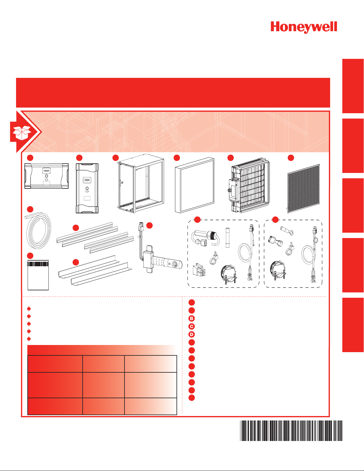
INCLUDED IN THIS ENHANCED AIR CLEANER BOX
1
A
F
2
A
1
G
I
J
STARTED
ECB D
2
J
GETTING
MOUNTING
WIRING
K
H
Tools needed to install Enhanced Air Cleaner
Standard screwdriver
Phillips screwdriver
Metal cutter
Drill
Duct Sealant
Replacement Filter Table
Enhanced Air
Cleaner
Air Handlers FH8000A1620
Forced Air Furnace FH8000F1625
Honeywell
Model
FH8000A2020
FH8000A2520
FH8000F2025
Replacement
Filter Part Number
FR8000A1620
FR8000A2020
FR8000A2520
FR8000F1625
FR8000F2025
Door FH8000A
1
A
Door FH8000F
2
A
Cabinet
Filter
Enhancement module
Safety screen
E
Duct gasket tape
F
Return duct adapters
G
Furnace adapters (FH8000F)
H
Air flow sensor (FH8000A)
I
Installation components (FH8000A)
1
J
Installation components (FH8000F)
2
J
K
Installation Instructions
AND SERVICE
OPERATION
APPENDICES
Page 2

Page 3

TrueCLEAN™ Enhanced Air Cleaner
GETTING STARTED
What to Expect From Your Honeywell
TrueCLEAN™ Enhanced Air Cleaner ....................................2
How it Works ........................................................................ 2
Application Considerations ..................................................3
Important Installation Requirements ...................................5
Personal Safety....................................................................5
MOUNTING
Choosing a Mounting Method ..............................................6
Which Honeywell Enhanced Air Cleaner model
do you have? .......................................................................6
Mounting the FH8000A (Air Handler) Honeywell
Enhanced Air Cleaner ..........................................................7
Mounting the FH8000F (Furnace) Honeywell
Enhanced Air Cleaner ........................................................10
WIRING
Before Wiring the Honeywell Enhanced Air
Cleaner ..............................................................................14
Wiring the FH8000A (Air Handler) Honeywell
Enhanced Air Cleaner ........................................................15
Wiring the FH8000F (Furnace) Honeywell
Enhanced Air Cleaner ........................................................17
OPERATION AND SERVICE
Startup and Operation .......................................................19
Checking Air Cleaner Operation .........................................19
Maintenance ......................................................................20
Troubleshooting ................................................................. 23
APPENDICES
Specications, Dimensions, and Approvals .......................25
Parts List ............................................................................28
Warranty ............................................................................29
STARTED
GETTING
MOUNTING
WIRING
NEED HELP? For assistance with this product please visit http://yourhome.honeywell.com
?
or call Honeywell Customer Care toll-free at 1-800-468-1502.
AND SERVICE
OPERATION
APPENDICES
Read and save these instructions.
® U.S. Registered Trademark. Patents pending. Copyright © 2010 Honeywell International Inc. All rights reserved.
TrueCLEAN™ Enhanced Air Cleaner 68-0308EFS—03
1
Page 4

GETTING
STARTED
What to Expect From Your Honeywell TrueCLEAN™ Enhanced
Air Cleaner
Congratulations for selecting the Honeywell TrueCLEAN™ Enhanced Air Cleaner for your home comfort system!
The Honeywell Enhanced Air Cleaner is proven to remove and destroy airborne germs and allergens, including
viruses, bacteria, and mold spores from air moving through the lter. The Honeywell Enhanced Air Cleaner is a
cornerstone of Honeywell’s home comfort solutions for providing cleaner air in your home.
The installer should review these points with the homeowner and answer any questions they have before leaving
the job site.
When Installing this Product...
1. Read these instructions carefully. Failure to follow them could damage the product or cause a hazardous
condition.
2. Check the rating given in the instructions and on the product to make sure the product is suitable for your
application.
3. Installer must be a trained, experienced service technician.
4. After installation is complete, check out product operation as provided in these instructions.
How it Works
The Honeywell TrueCLEAN™ Enhanced Air Cleaner provides extremely high ltration performance while
destroying captured contaminants, including viruses, bacteria, and mold spores. The Honeywell Enhanced Air
Cleaner treats the entire air stream through a state of the art, three-stage process.
Stage 1
In stage one, particles in the air are electrically charged by an array of ionizer points as they enter the Honeywell
Enhanced Air Cleaner.
Stage 2
In stage two, the charged particles are electrically attracted and captured in the air lter cartridge, which is located
within an electric eld.
Stage 3
In stage three, captured particles are destroyed by electrical current ow and ion bombardment.
2
TrueCLEAN™ Enhanced Air Cleaner 68-0308EFS—03
Page 5

Application Considerations
The Honeywell Enhanced Air Cleaner is designed for use in the return air duct of a forced air heating, cooling,
and ventilation system. Models FH8000A1620, FH8000A2020 and FH8000A2520 are specically designed for
use in systems with an air handler. Models FH8000F1625 and FH8000F2025 are specically designed for use in
systems with a forced air furnace. The Honeywell Enhanced Air Cleaner is CSA certied for shock and electrical
re hazard only.
Air Conditioning
The Honeywell Enhanced Air Cleaner should be installed in a system so that all the return air is circulated through
the Honeywell Enhanced Air Cleaner. It should be located upstream of the air conditioning equipment. This
will help keep the equipment clean and prevent condensation from forming within the Honeywell Enhanced Air
Cleaner.
Humidiers
An evaporative humidier can be mounted upstream of the Honeywell Enhanced Air Cleaner. It is best to install
atomizing humidiers downstream of the Honeywell Enhanced Air Cleaner because hard water salt deposits and
water droplets may damage the Honeywell Enhanced Air Cleaner. If an atomizing humidier must be mounted
upstream of the Honeywell Enhanced Air Cleaner, it should be mounted as far upstream as possible (at least 6 ft.
[1.8 m] recommended), and a standard disposable furnace lter should be mounted between the humidier and
the Honeywell Enhanced Air Cleaner to trap hard water salt deposits and water droplets.
STARTED
GETTING
Transitions
If the return air duct or fan coil openings do not t the Honeywell Enhanced Air Cleaner cabinet openings, gradual
transitions are recommended to reduce air turbulence and maximize efciency.
FH8000A – No more than 20 degrees (about 4 in. per running ft.) of expansion should be used on each side of
the transition tting.
FH8000F – No more than 45 degrees (about 8.5 in. per running ft.) of expansion should be used on each side of
the transition tting.
Turning Vanes
If the Honeywell Enhanced Air Cleaner is installed adjacent to a 90 degree duct elbow, turning vanes should be
added inside duct to improve air distribution across the face of the Honeywell Enhanced Air Cleaner.
TrueCLEAN™ Enhanced Air Cleaner 68-0308EFS—03
3
Page 6
GETTING
STARTED
Application Considerations
Electrical Power / Airow Switch
The Honeywell Enhanced Air Cleaner should only be powered when airow is present.
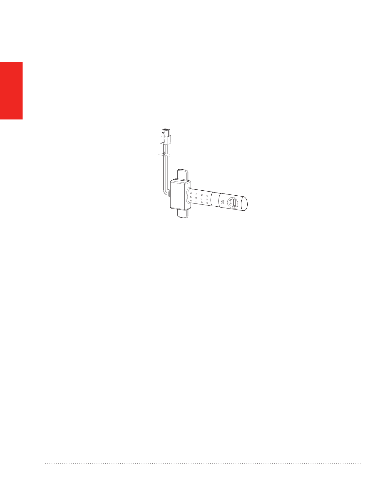
FH8000A – These models are designed for use with an air handler and are equipped with an airow switch (see
Fig. 1), which provides power only when the air handler blower is operating. These models are designed to be
powered from a 208 to 230 VAC single phase power source.
Fig. 1. Airow Switch.
FH8000F – The furnace control EAC terminals provide power to the unit only when the furnace blower is
operating. These models are designed to be powered from the electronic air cleaner (EAC) terminals on a furnace
control board. If EAC terminals are not available, an alternative airow sensing mechanism such as the Honeywell
50027910-001 Differential Pressure Switch must be used to ensure the Honeywell Enhanced Air Cleaner is only
powered when airow is present. Contact your local Honeywell distributor for information on alternatives.
4
TrueCLEAN™ Enhanced Air Cleaner 68-0308EFS—03
Page 7

Important Installation Requirements
Failure to comply with these requirements will result in voided warranty, improper installation, and
service callbacks.
Personal Safety
• Wear safety glasses while installing the unit.
• Do not cut into any air conditioning or electrical line.
• Follow professional safety standards and all local codes for plumbing, electrical, and mechanical
considerations.
Before Mounting
• Using the gure on the cover and the lists on the inside cover, make sure that you have all the components for
your Honeywell Enhanced Air Cleaner model and the tools to install it.
• Ensure airow direction through the Honeywell Enhanced Air Cleaner matches the arrows on the face of the
lter. The arrows should point towards heating/cooling equipment. The door can be rotated 180 degrees to
accommodate the cabinet orientation.
• The location of the Honeywell Enhanced Air Cleaner should be readily accessible. Enough clearance room
should be provided for periodic replacement of the lter.
STARTED
GETTING
If Replacing an Old Air Cleaner
If the Honeywell Enhanced Air Cleaner is not identical in size and shape to the existing air cleaner, before
performing a retrot installation, you might need to add duct transitions to ensure a smooth air ow.
Replacement Filters
Replacement Filter Table
Enhanced Air Cleaner Honeywell
Model
Air Handlers FH8000A1620
FH8000A2020
FH8000A2520
Forced Air Furnace FH8000F1625
FH8000F2025
Replacement Filter
Part Number
FR8000A1620
FR8000A2020
FR8000A2520
FR8000F1625
FR8000F2025
TrueCLEAN™ Enhanced Air Cleaner 68-0308EFS—03
5
Page 8
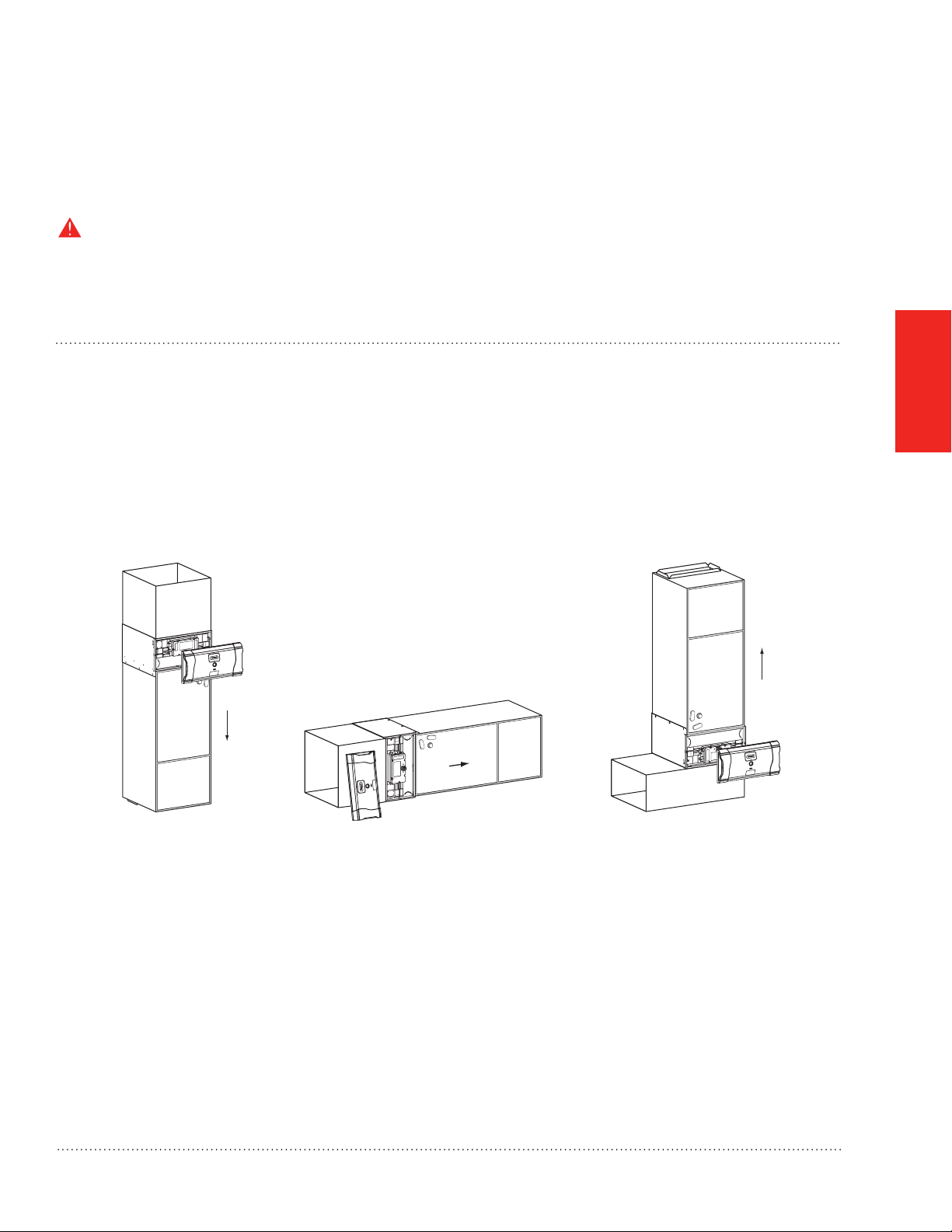
Choosing a Mounting Method
There are two Honeywell Enhanced Air Cleaner designs. One designed for air handlers and one designed for
furnaces. Follow the installation instructions for the Air Cleaner model you have:
Which Honeywell Enhanced Air Cleaner model do you have?
MOUNTING
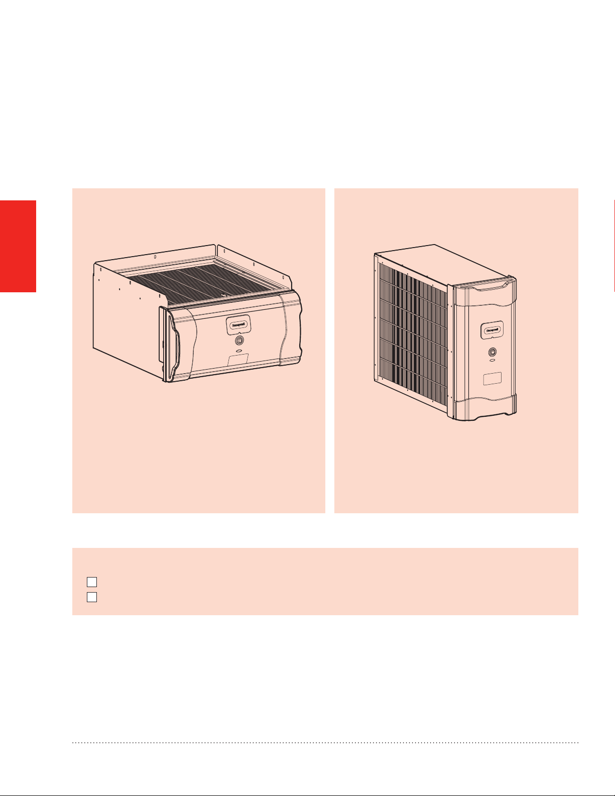
Models FH8000A for air handlers:
These models are installed upstream of the air handler.
This will help keep the air handler clean.
M28900
Fig. 2. Model FH8000A Honeywell Enhanced Air
Cleaner.
Models FH8000F for furnaces:
These models are installed upstream of both the
furnace and the air conditioning evaporator coil.
M28901
Fig. 3. Model FH8000F Honeywell Enhanced Air
Cleaner.
Before beginning Mounting:
I have conrmed local codes for proper electrical wiring practices.
I have chosen an installation location that meets the requirements on pages 3 through 5.
NOTE: To mount the FH8000A (Air Handler) Honeywell Enhanced Air Cleaner, go to page 7.
NOTE: To mount the FH8000F (Furnace) Honeywell Enhanced Air Cleaner, go to page 10:
6
TrueCLEAN™ Enhanced Air Cleaner 68-0308EFS—03
Page 9
Mounting the FH8000A (Air Handler) Honeywell Enhanced Air
Cleaner
NOTE: For mounting a FH8000F model go to page 10.
CAUTION: Personal Injury Hazard.
Failure to follow this caution may result in personal injury. Sheet metal parts may have sharp edges or burrs.
Use care and wear appropriate protective clothing, eye protections, and gloves when handling parts.
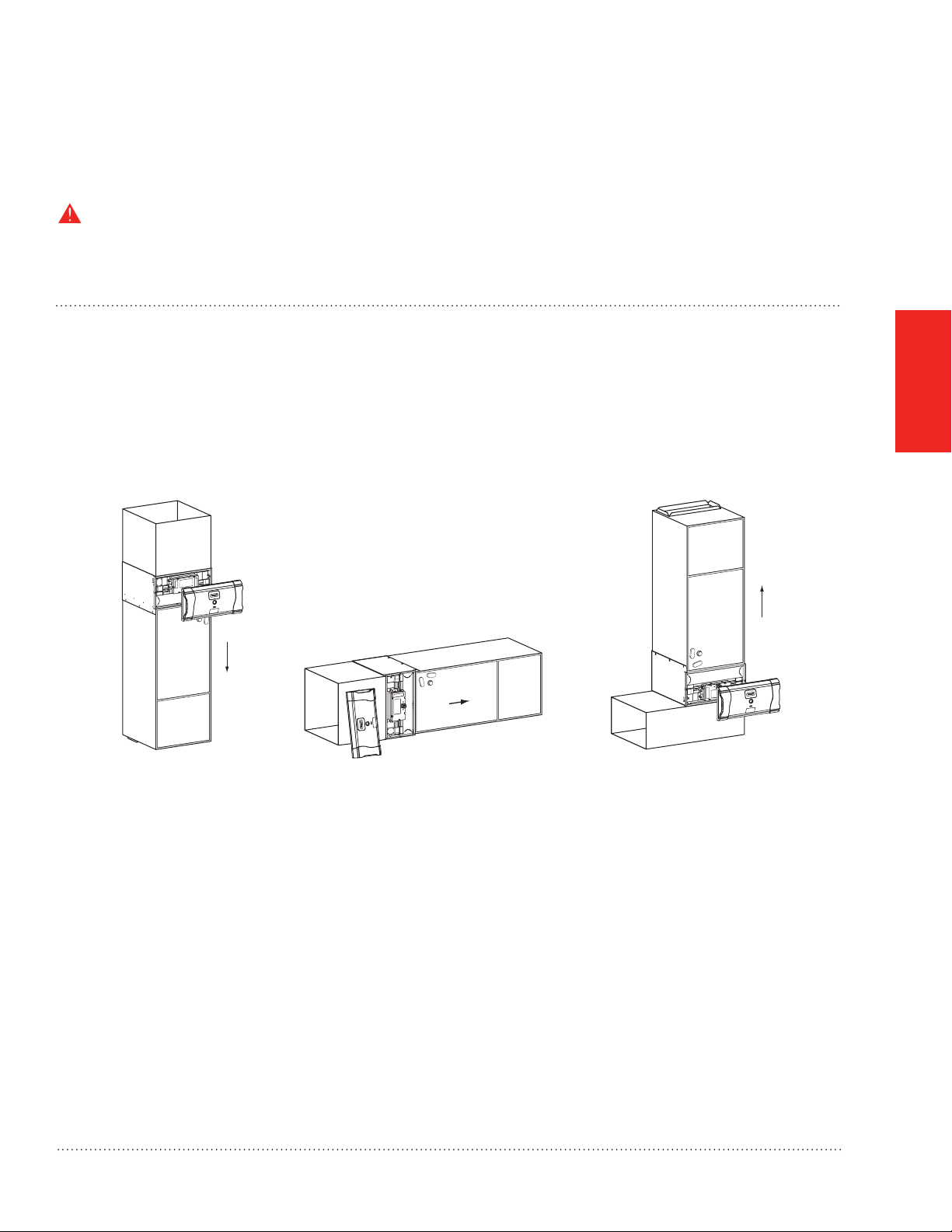
STEP ONE: Identify the Mounting Location and Orientation
a. Identify a mounting orientation for the Honeywell Enhanced Air Cleaner in the return air duct (see Fig. 4).
b. Ensure airow direction through the Honeywell Enhanced Air Cleaner matches the arrows on the face of the
lter. The Honeywell Enhanced Air Cleaner or door can be rotated 180 degrees to accommodate the cabinet
orientation.
c. The location of the unit should be readily accessible. Enough room should be provided to remove the door and
lter for periodic replacement of the air lters.
Airflow
Airflow
Downflow Horizontal Upflow
Airflow
MOUNTING
Fig. 4. Cabinet Orientation for FH8000A models.
TrueCLEAN™ Enhanced Air Cleaner 68-0308EFS—03
M28902
7
Page 10
MOUNTING
Mounting the FH8000A (Air Handler) Honeywell Enhanced Air
Cleaner
STEP TWO: Mount Cabinet
WARNING: Electrocution and Unit Damage Hazard.
Failure to follow this warning could result in personal injury or death.
Only a trained, experienced service person should install the Honeywell Enhanced Air Cleaner. A thorough
check of the unit installation should be completed before unit operation. Before performing installation,
service or maintenance operations on unit, turn off all power to unit.
1. Before installing or servicing system, always turn off main power to system. There may be more than one
disconnect switch.
2. Cabinets will support a maximum weight of 400 lbs. (181 kg) when installed beneath a vertical furnace or
air-handling unit. When setting furnace on cabinet, do not drop it into place. Position the furnace correctly on
the cabinet to prevent a corner from slipping down and damaging the cabinet or its components.
a. Turn off power to the heating and cooling system.
b. Remove the existing air handler lter and discard. Excessive system static pressure may result if the
Honeywell Enhanced Air Cleaner is used with other ltration devices.
c. Remove the lter and enhancement module from the Honeywell Enhanced Air Cleaner cabinet.
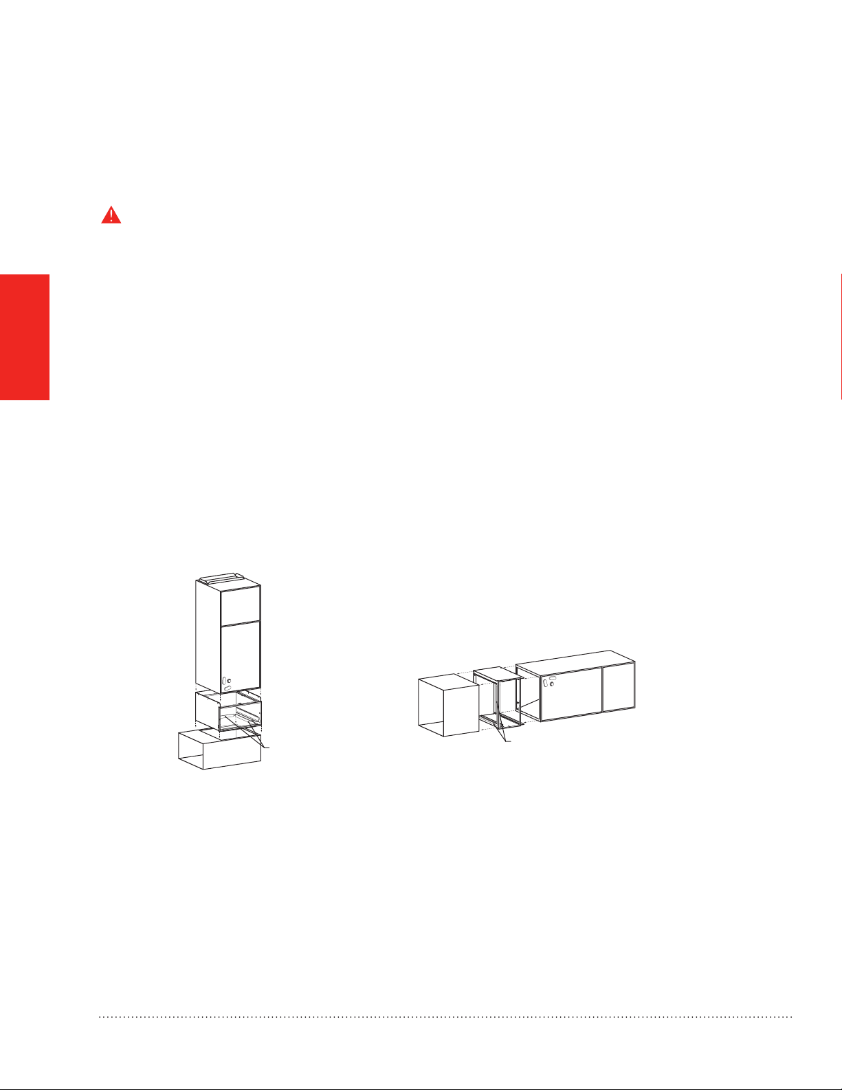
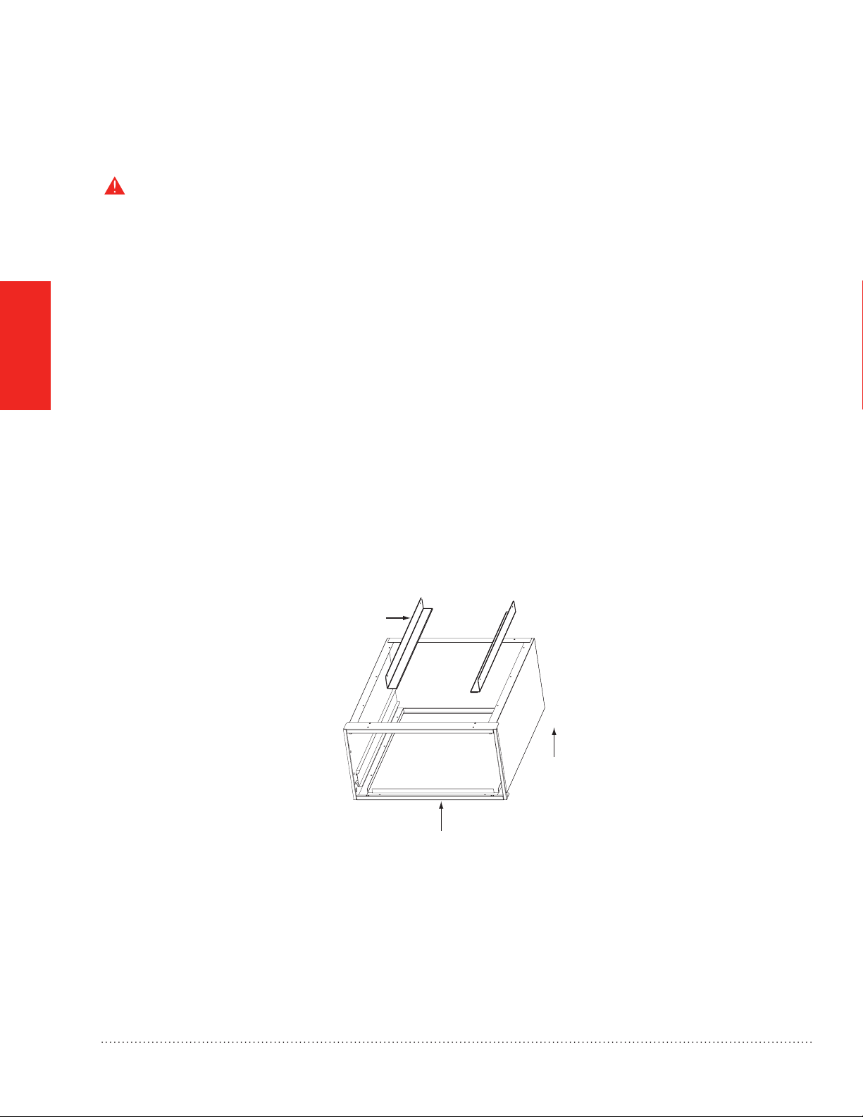
d. Position the cabinet between the air handler and return air duct (see Fig. 4 on page 7 and Fig. 5).
A transition duct may be required.
RETURN DUCT
ADAPTERS (X4)
MOUNTINGCABINET VERTICAL
MOUNTINGCABINET HORIZONTAL
RETURN DUCT
ADAPTERS (X4)
M28903
Fig. 5. Orientation for FH8000A models for Air Handlers.
NOTES:
1. The air handler cabinet screws holding the lter rack should be used to attach the Honeywell
Enhanced Air Cleaner cabinet.
2. Gasket tape between the air handler and the Honeywell Enhanced Air Cleaner cabinet is already
factory installed.
3. Mounting holes are provided for the air handler attachment.
8
TrueCLEAN™ Enhanced Air Cleaner 68-0308EFS—03
Page 11
Mounting the FH8000A (Air Handler) Honeywell Enhanced Air
Cleaner
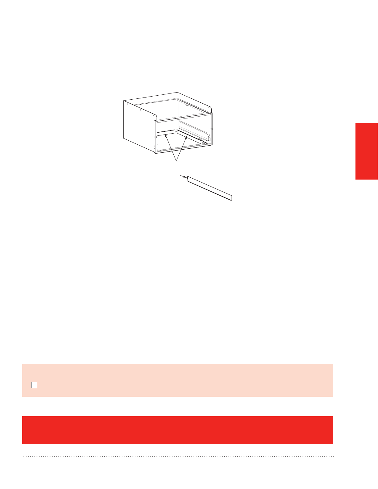
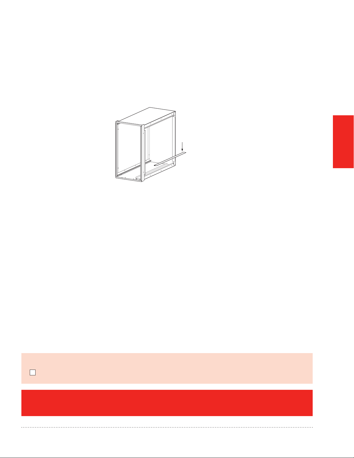
e. Use return duct adapters provided to attach return ductwork (see Fig. 6).
f. Seal seams with tape or caulking after the Honeywell Enhanced Air Cleaner cabinet has been secured.
RETURN DUCT ADAPTORS
NOTE:
SLIP THE ADAPTOR S-CLEATS
ONTO FLANGES
ON THE RETURN DUCT SIDE.
MOUNTING
M28904
Fig. 6. Use of Return Duct Adapters for FH8000A.
Before proceeding to Wiring on page 14:
I mounted and secured the Honeywell Enhanced Air Cleaner cabinet to the duct as instructed.
FH8000A Mounting is complete. Go to page 14.
TrueCLEAN™ Enhanced Air Cleaner 68-0308EFS—03
9
Page 12
MOUNTING
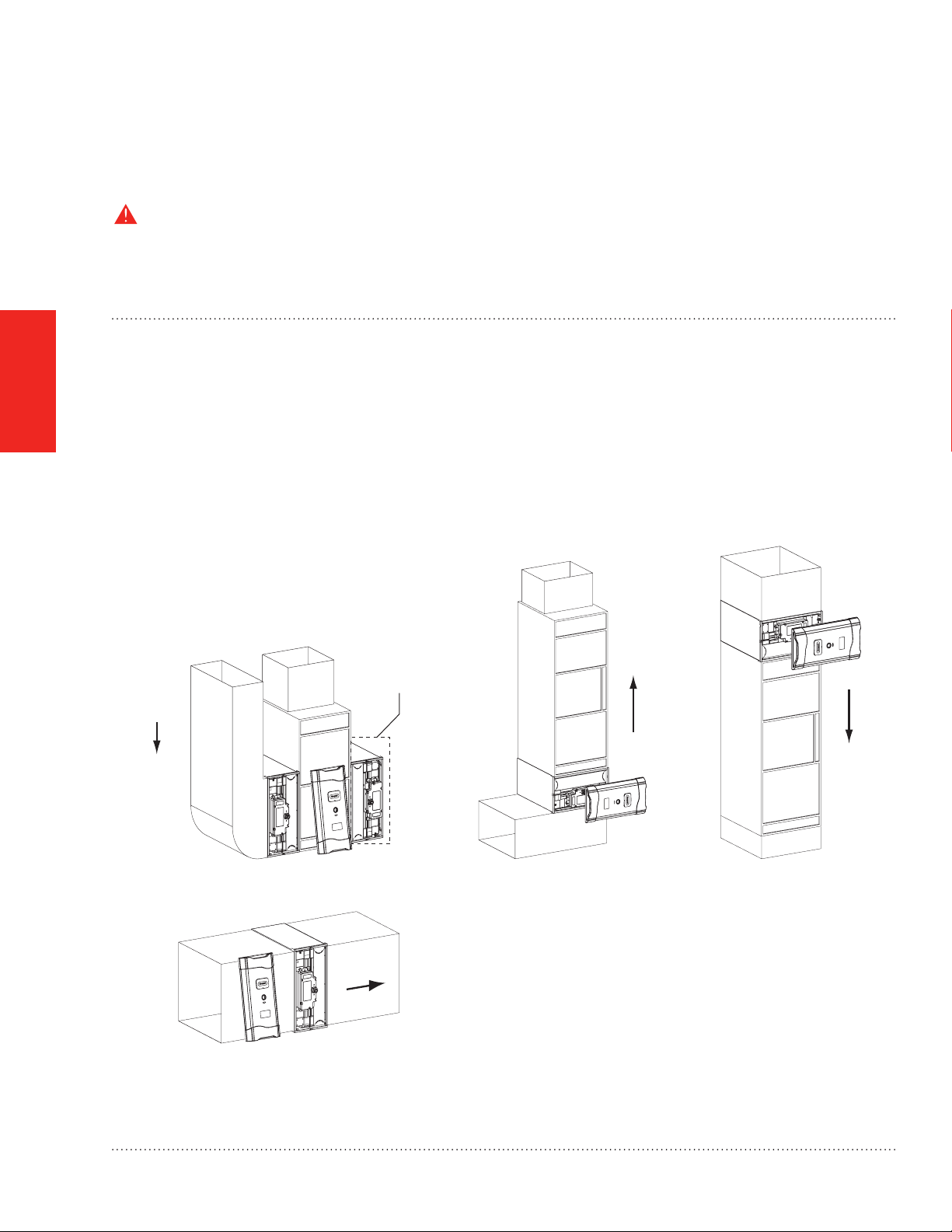
UPFLOW FURNACE WITH BOTTOM MOUNT DOWNFLOW FURNACE WITH BOTTOM MOUNTUPFLOW FURNACE WITH SIDE RETURN
HORIZONTAL APPPLICATION
M28905
AIRFLOW
NOTE:
MOUNTING ON THIS SIDE
REQUIRES THE CABINET
TO BE ROTATED 180° FOR
CORRECT AIRFLOW.
A
IRFLOW
AIRFLOW
AIRFLOW
Mounting the FH8000F (Furnace) Honeywell Enhanced Air
Cleaner
NOTE: For mounting a FH8000A model go back to page 7.
CAUTION: Personal Injury Hazard.
Failure to follow this caution may result in personal injury. Sheet metal parts may have sharp edges or burrs.
Use care and wear appropriate protective clothing and gloves when handling parts.
STEP ONE: Identify the Mounting Location and Orientation
a. Identify a mounting orientation for the Honeywell Enhanced Air Cleaner in the return air duct. See Fig. 7 and
Fig. 8 on page 11.
b. Ensure airow direction through the Honeywell Enhanced Air Cleaner matches the arrows on the face of the
air lter cartridge. The Honeywell Enhanced Air Cleaner door can be rotated 180 degrees to accommodate the
cabinet orientation.
c. The location of the unit should be readily accessible. Enough clearance room should be provided to remove
the door and lter for replacement.
Fig. 7. Cabinet Orientation for FH8000F models.
10
TrueCLEAN™ Enhanced Air Cleaner 68-0308EFS—03
Page 13
Mounting the FH8000F (Furnace) Honeywell Enhanced Air
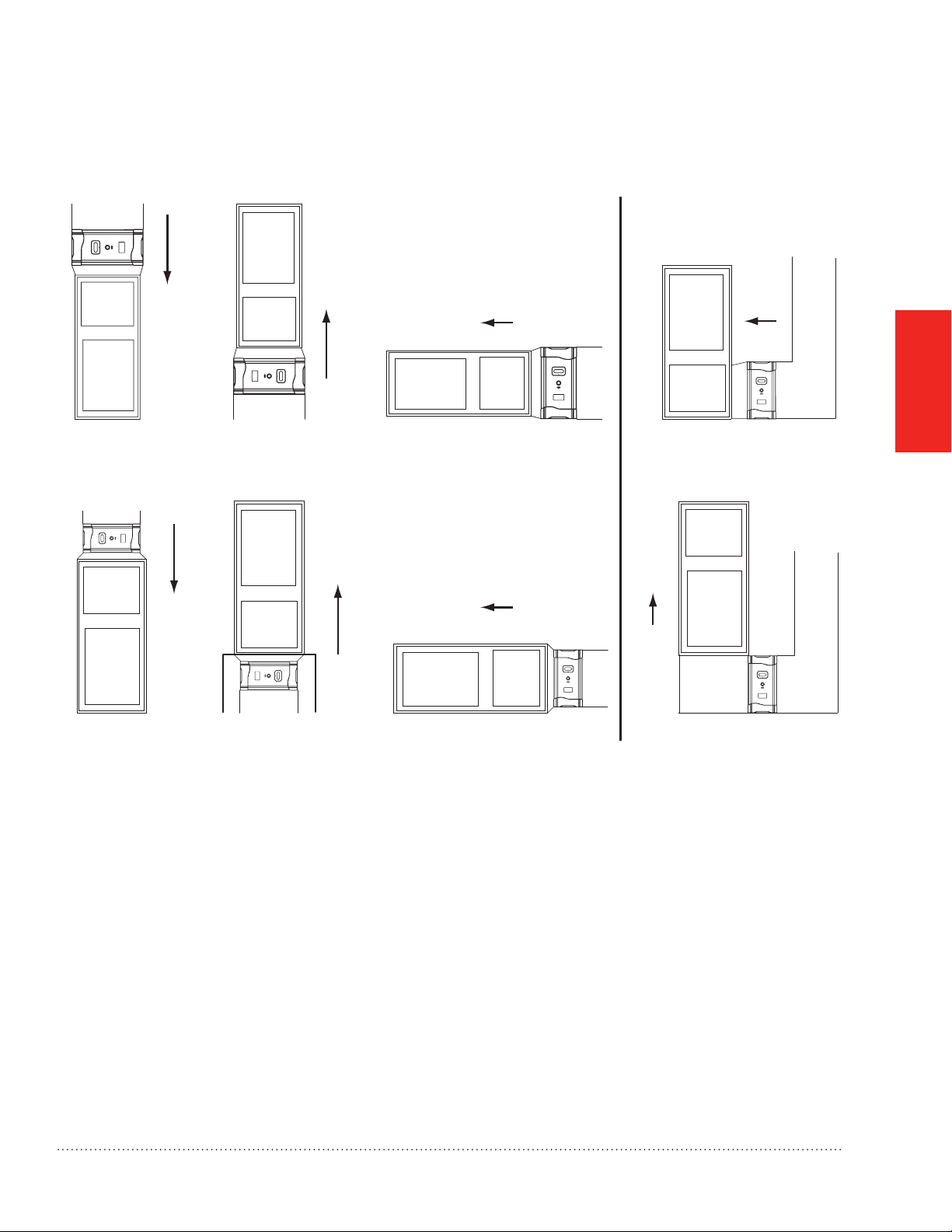
NOTE: WHEN TRANSITIONING BEWTWEEN TWO DIFFERENT SIZED COMPONENTS (FURNACE AND AIR CLEANER),
Cleaner
THE MINIMUM TRANSITION ANGLE AT THE LARGER OF THE TWO COMPONENTS MUST BE NO LESS THAN 45 DEGREES.
AIRFLOW
AIRFLOW
AIRFLOW
DOWNFLOW 14” FURNACE
WITH TOP MOUNT
AIRFLOW
WITH TOP MOUNT
UPFLOW 14” FURNACE
WITH BOTTOM MOUNT
AIRFLOW
UPFLOW 24” FURNACE
ON STAND WITH BOTTOM MOUNT
HORIZONTAL 14” FURNACE
WITH SIDE MOUNT
AIRFLOW
Fig. 8. Cabinet Orientation for FH8000F with Transition.
AIRFLOW
PLENUM
UPFLOW FURNACE WITH PLENUM BOXHORIZONTAL 24” FURNACEDOWNFLOW 24” FURNACE
AIRFLOW
UPFLOW FURNACE
BOX
MOUNTING
M28906
TrueCLEAN™ Enhanced Air Cleaner 68-0308EFS—03
11
Page 14
MOUNTING
Mounting the FH8000F (Furnace) Honeywell Enhanced Air
Cleaner
STEP TWO: Mount Cabinet
WARNING: Electrocution and Unit Damage Hazard.
Failure to follow this warning could result in personal injury or death.
Only a trained, experienced service person should install the Honeywell Enhanced Air Cleaner. A thorough
check of the unit installation should be completed before unit operation. Before performing installation,
service or maintenance operations on unit, turn off all power to unit.
1. Before installing or servicing system, always turn off main power to system. There may be more than one
disconnect switch.
2. Cabinets will support a maximum weight of 400 lbs. (181 kg) when installed beneath a vertical furnace or
air-handling unit. When setting furnace on cabinet, do not drop it into place. Position the furnace correctly on
the cabinet to prevent a corner from slipping down and damaging the cabinet or its components.
a. Turn off power to the heating and cooling system.
b. Remove the existing furnace lter and discard. Excessive system static pressure may result if the Honeywell
Enhanced Air Cleaner is used with other ltration devices.
c. Remove the lter and enhancement module from the Honeywell Enhanced Air Cleaner cabinet.
d. Position the cabinet between the furnace and return air duct (see Fig 7 on page 10, Fig. 8 on page 11, Fig. 9,
and Fig. 10 on page 13). A transition duct may be required.
e. Furnace adapters have been included for installer convenience. They are designed for top or bottom mount
installations (see Fig 9).
FURNACE
ADAPTERS
AIRFLOW
Fig. 9. Use of Furnace Adapters.
AIRFLOW
M28907
12
TrueCLEAN™ Enhanced Air Cleaner 68-0308EFS—03
Page 15
Mounting the FH8000F (Furnace) Honeywell Enhanced Air
Cleaner
f. Return air duct adapters have been included for installer convenience. They should be used to connect the
upstream side of the Honeywell Enhanced Air Cleaner cabinet to the return air duct (see Fig. 10).
g. Install foam tape between the furnace and the Honeywell Enhanced Air Cleaner cabinet.
h. Mounting holes are provided for ductwork and furnace attachment.
i. Seal seams with tape or caulking after the Honeywell Enhanced Air Cleaner cabinet has been secured.
NOTE:
SLIP S-CLEATS ONTO FLAGES
ON RETURN DUCT SIDE.
M28897
Fig. 10. Use of Return Duct Adapters.
MOUNTING
Before proceeding to Wiring on page 14:
I mounted and secured the Honeywell Enhanced Air Cleaner cabinet to the duct as instructed.
FH8000F Mounting is complete. Go to page 14.
TrueCLEAN™ Enhanced Air Cleaner 68-0308EFS—03
13
Page 16

Before Wiring the Honeywell Enhanced Air Cleaner
WARNING: Electrocution Hazard.
Be sure the Honeywell Enhanced Air Cleaner is not plugged in before beginning wiring.
Failure to follow this warning could result in personal injury or death.
Before installing or servicing system, always turn off main power to system. There may be
more than one disconnect switch.
Before wiring the Honeywell Enhanced Air Cleaner:
I understand and will comply with applicable local wiring codes and regulations.
WIRING
NOTE: To wire the FH8000A models, go to page 15.
NOTE: To wire the FH8000F models, go to page 17.
14
TrueCLEAN™ Enhanced Air Cleaner 68-0308EFS—03
Page 17
Wiring the FH8000A (Air Handler) Honeywell Enhanced Air
Cleaner
STEP ONE: Wiring the FH8000A (Air Handler)
a. Ensure power has been shut off from the heating and cooling system.
b. Turn the Honeywell Enhanced Air Cleaner power switch off.
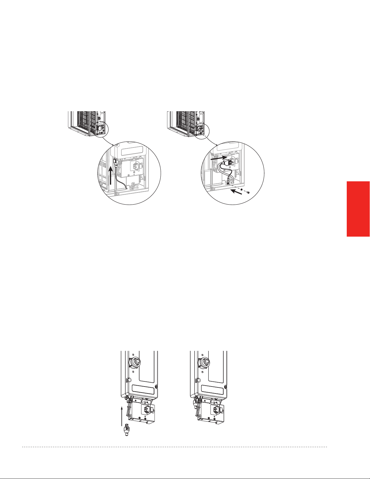
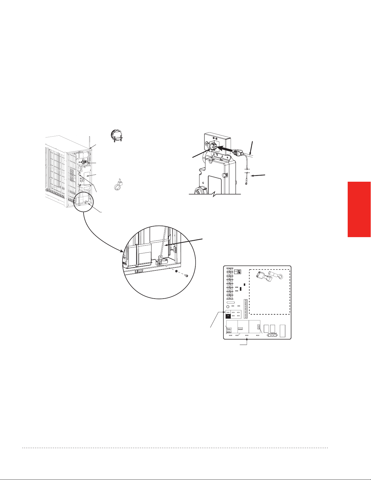
c. Plug the power cord and the airow switch cord into their power supply connectors (see Fig. 11).
d. Secure the power cord ground wire to the ground terminal on the cabinet using the screw provided in the
ground terminal (see Fig 11).
WIRING
AIRFLOW SWITCH CABLE INSTALLED
Fig. 11. Airow switch cable and Power cable installation.
POWER CORD INSTALLED AND
GROUND WIRE SECURED TO TERMINAL
M31365
NOTE: The power cord can be routed through either side of the cabinet. As needed, use the enclosed Zip ties to
secure the power cord to the side of the power supply.
NOTE: Cable connector and block-off plates will need to be removed and re-installed if the power cord is re-
routed. Screws on the cable connector clamp should be tightened to 9 in-lbs. torque.
NOTE: The Air Handler Honeywell Enhanced Air Cleaner is to be powered by 208 to 230 VAC at 60 Hz.
NOTE: The Honeywell Enhanced Air Cleaner should only be powered when airow is present. An airow switch
is factory-installed. See Fig. 1 on page 4 and Fig. 14 on page 16. In order to bypass the airow sensor
for troubleshooting, use the special bypass jumper plug (see Fig. 12) included in the parts bag. With the
bypass jumper in place, the air cleaner will be on at all times when connected to electrical line power. The
bypass jumper is not to be used for normal operation.
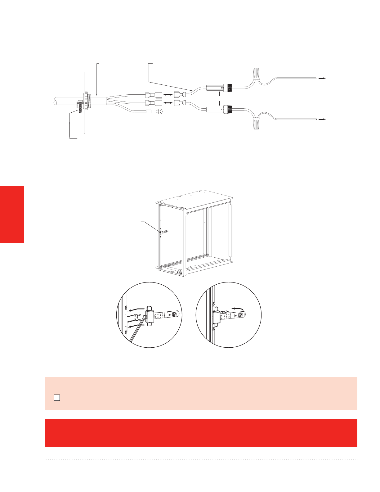
e. Attach the quick connect terminals to the fused power connector leads (in parts bag attached to power cord)
and connect to incoming eld power. The terminals are polarity neutral and can be connected in either polarity.
Attach the ground ring to air handler chassis ground (see Fig. 13 on page 16).
Fig. 12. Airow sensor Bypass Jumper Plug installed.
TrueCLEAN™ Enhanced Air Cleaner 68-0308EFS—03
M28910
15
Page 18
Wiring the FH8000A (Air Handler) Honeywell Enhanced Air
FUSED POWER CONNECTOR LEADS
AIR PURIFIER
Cleaner
WIRING
POWER CORD
CABLE CONNECTOR
TO SECURE POWER CORD
TO AIR HANDLER CABINET
Fig. 13. Honeywell Enhanced Air Handler chassis ground.
AIR FLOW SENSOR
FROM INSTALLATION COMPONENTS
(IN BAG ATTACHED TO POWER CORD)
GROUND:
AT TACH TO AIR HANDLER
GROUND (CHASSIS)
5 AMP IN-LINE FUSES
TO L2 FIELD POWER SUPPLY
TO AIR HANDLER FIELD POWER CONNECTION
TO L1 FIELD POWER SUPPLY
M28911
1) SLIDE FLOW SENSOR TABS
INTO SUPPORT BRACKET
2) ROTATE FLOW SENSOR
AND CLIP INTO BRACKET
M28912
Fig. 14. Airow Switch installation.
Before proceeding to Startup and Operation on page 19:
I wired the Honeywell Enhanced Air Cleaner as instructed.
FH8000A Wiring is complete. Go to page 19.
16
TrueCLEAN™ Enhanced Air Cleaner 68-0308EFS—03
Page 19
Wiring the FH8000F (Furnace) Honeywell Enhanced Air Cleaner
STEP ONE: Wiring the FH8000F (Furnace)
a. Ensure power has been removed from the heating and cooling system.
b. Turn the Honeywell Enhanced Air Cleaner power switch off.
c. Connect the power cord to the power supply connector (see Fig. 15).
d. Secure the power cord ground wire to the ground terminal on the cabinet using the screw provided in the
ground terminal (see Fig 15).
POWER CORD
TO EAC
TERMINALS
USE CABLE CONNECTOR
TO SECURE POWER
CORD TO CABINET
POWER SUPPLY
CONNECTOR
POWER SUPPLY
USE WIRE TIES TO SECURE
POWER CORD TO
POWER SUPPLY ENCLOSURE
POWER
SUPPLY
CONNECTOR
POWER CORD
GROUND WIRE
TO BE SECURED
TO CABINET
(SEE DETAIL A)
WIRING
ALTERNATE POWER CORD
PASS-T HRU HOLE
GROUND WIRE
FROM POWER CORD
SAMPLE FURNACE CIRCUIT BOARD
ON
OFF
W2
1 2 3
LHT
OFF
Y1 DHUM GCOM
DLY
DETAIL A
EAC-2 TERMINAL
EAC-1 TERMINAL
24V
WW1Y/Y2R
FUSE 3-AMP
A
T
S
D
E
L
E
D
EAC-2
BLW
HI HEAT
LO HEAT
SPARE-1 SPARE-2
T
SEC-1 SEC-2
U
S
C
O
NEUTRAL-L2
TEST/TWIN
HUM
0.5-AMP024 VAC
COOL
PLT
PL1
1
1-AMP@115 VAC
ACRDJ
BHT/CLR RWLBROL/IHB
EAC-1 PR-1
USE TERMINALS TO
CONNECT THE
POWER CORD
WIRES TO THE
FURNACE
EAC-1, EAC2, AND
GROUND TERMINALS.
IHI/LOR
HSIR
IDR
IDM
1
L1
PL2
HSI HI LO
M31366
Fig. 15. Electrical connections.
e. Route the power cord through nearest cabinet hole and protect with enclosed cable connector. Zip ties have
been enclosed to secure the power cord to the side of the power supply.
TrueCLEAN™ Enhanced Air Cleaner 68-0308EFS—03
17
Page 20

Wiring the FH8000F (Furnace) Honeywell Enhanced Air
Cleaner
f. Attach the quick connect terminals to the furnace EAC-1 and EAC-2 spade connections, which are polarity
neutral.
g. Attach the ground ring to furnace chassis ground.
NOTE: The FH8000F Honeywell Enhanced Air Cleaner is to be powered by 120 VAC at 60 Hz.
NOTE: The Honeywell Enhanced Air Cleaner should only be powered when airow is present. The furnace
control EAC spade connections provide power only when the furnace blower is operating. If EAC
connections are not available, an alternative airow sensing mechanism such as the Honeywell
50027910-001 Differential Pressure Switch must be used to ensure the Honeywell Enhanced Air
Cleaner is only powered when airow is present. Contact a local Honeywell distributor for information on
alternative airow sensors.
WIRING
Before proceeding to Startup and Operation on page 19:
I wired the Honeywell Enhanced Air Cleaner as instructed.
FH8000F Wiring is complete. Go to page 19.
18
TrueCLEAN™ Enhanced Air Cleaner 68-0308EFS—03
Page 21
Startup and Operation
Checking Air Cleaner Operation
WARNING: Electrocution Hazard.
Failure to follow this warning could result in personal injury or death.
Before installing or servicing system, always turn off main power to system. There may be more than one
disconnect switch.
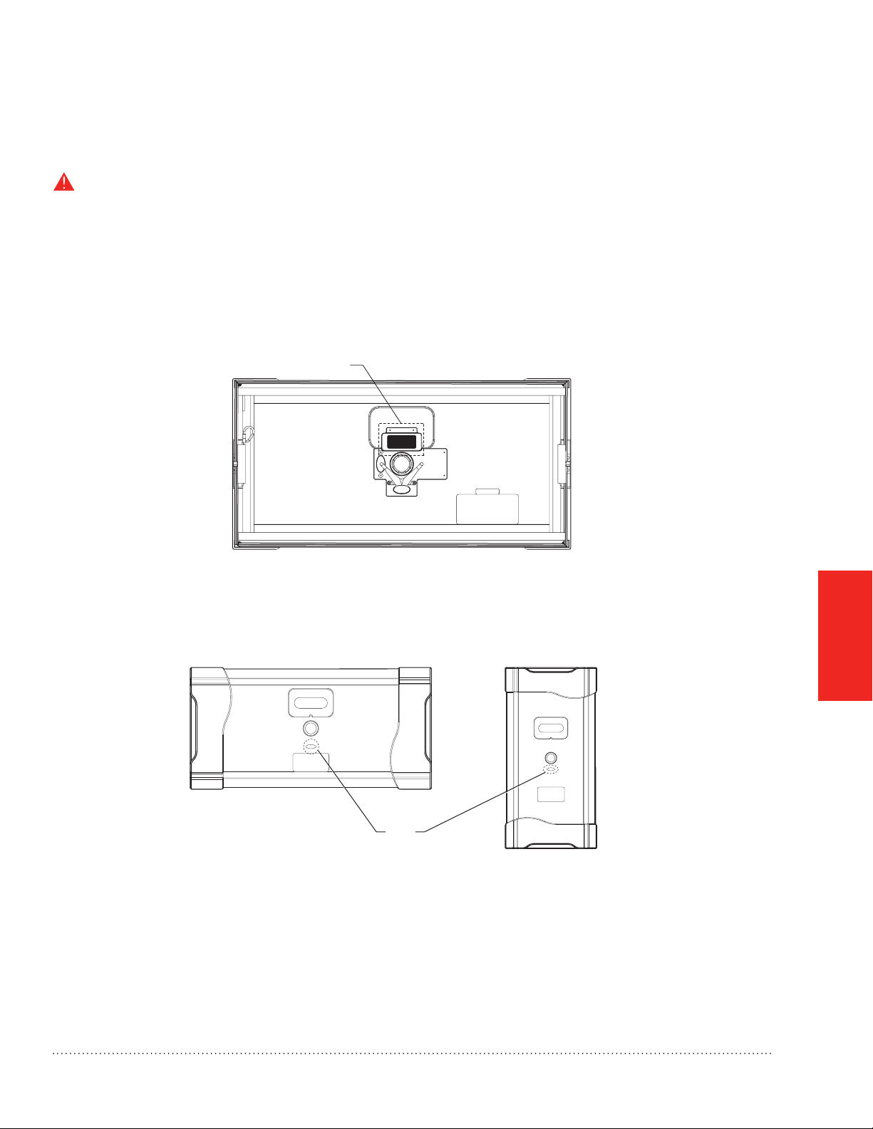
a. Attach the Honeywell Enhanced Air Cleaner door to the cabinet. A magnet in the door (see Fig. 16) is used to
activate a safety switch in the power supply when the door is installed. The power supply will not energize the
air cleaner unless the safety switch is activated.
DOOR SWITCH MAGNET
M28914
Fig. 16. Door Switch Magnet
b. Turn the HVAC system power on and adjust the thermostat to activate the system fan.
c. Turn the Honeywell Enhanced Air Cleaner power switch to on position.
d. The power indicator light below the Honeywell Enhanced Air Cleaner power switch will illuminate (see Fig. 17).
MODEL FH8000A
POWER
INDICATOR
MODEL FH8000F
M28915A
Fig. 17. Power Indicator
e. Check to ensure the light goes off when the Honeywell Enhanced Air Cleaner power switch is set to off, when
the blower goes off, or when the HVAC system power is turned off.
AND SERVICE
OPERATION
NOTE: Upon powerup for the FH8000A models, the light comes on for about 5 seconds and, if no ow is
detected, it goes off. If no air lter cartridge is detected, the ow sensor detects this and turns the
Honeywell Enhanced Air Cleaner off after about 7 seconds.
TrueCLEAN™ Enhanced Air Cleaner 68-0308EFS—03
19
Page 22
Maintenance
The Honeywell Enhanced Air Cleaner is designed to require minimal maintenance. Maintenance is limited to
the replacement of the lter and periodic inspection/brush cleaning of the ionization array. Frequency of air lter
cartridge replacement and cleaning of the ionization array may vary depending on ductwork design and local
environmental conditions.
To replace the air lter cartridge, complete the following steps:
1. Turn heating and cooling system power off.
WARNING: Electrocution Hazard.
Failure to follow this warning could result in personal injury or death.
Before installing or servicing system, always turn off main power to system. There may be more than one
disconnect switch.
2. Turn the Honeywell Enhanced Air Cleaner switch to the off position.
3. Remove the Honeywell Enhanced Air Cleaner door.
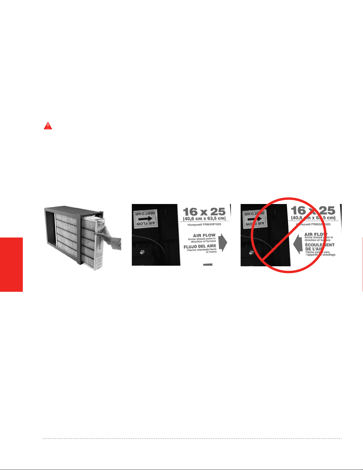
4. Slide out the old lter and discard.
5. Install the new lter.
OPERATION
AND SERVICE
Fig. 18: Make sure that the arrows on the lter point in the same direction as the arrow on the enhancement
module. This will be in the same direction as airow.
NOTE: Replace lter at least annually; more often if needed.
6. Replace the Honeywell Enhanced Air Cleaner door.
7. Turn the Honeywell Enhanced Air Cleaner switch to the on position.
8. Turn heating and cooling system power on.
20
TrueCLEAN™ Enhanced Air Cleaner 68-0308EFS—03
Page 23

Maintenance
At the time of lter replacement, if a powdery residue is noticed on the tips of the points
in the ionization array of the Enhancement module, proceed to clean them by completing the following steps:
1. Turn heating and cooling system power off.
WARNING: Electrocution Hazard.
Failure to follow this warning could result in personal injury or death.
Before installing or servicing system, always turn off main power to system. There may be more than one
disconnect switch.
2. Turn the Honeywell Enhanced Air Cleaner switch to the off position.
3. Remove the Honeywell Enhanced Air Cleaner door.
4. Models FH8000A: Unplug the power cord and ow sensor cable (if connected) from the enhancement
module (see Fig. 11 on page 15).
Models FH8000F: Unplug the power cord from the enhancement module (see Fig. 15 on page 17).
5. Slide out the enhancement module assembly and safety screen.
CAUTION: Personal Injury Hazard.
Failure to follow this caution may result in personal injury.
Ionizer points are SHARP and may cause injury. Use caution and wear appropriate protective clothing and
gloves when handling parts or performing maintenance.
6. Slide out the Safety Screen and set aside.
NOTE: Best cleaning tools: 2 in. (51 mm) wide (or greater) synthetic or natural bristle brush with a
5 in. (157 mm) handle (see Fig. 18) or vacuum cleaner with brush attachment.
7. Gently stroke the ionization points on the top plane of each bar with enough brush depth to hit front and
back tips of the points in the ionization array. Use a gentle back and forth brushing motion to clean any small
accumulations from the tips of the points. If desired, use vacuum cleaner with brush attachment to gently
vacuum the frame and components of enhancement module. (See Fig. 19 on next page.)
AND SERVICE
OPERATION
TrueCLEAN™ Enhanced Air Cleaner 68-0308EFS—03
21
Page 24

ENHANCEMENT MODULE
Maintenance
30°
POINTS ARESHARP!BE VERY CAREFUL DURING CLEANING.
OPERATION
AND SERVICE
IONIZER POINT WITH RESIDUE IONIZER POINT AFTER CLEANING
Fig. 19. Removal of deposits from ionization points.
8. Reinstall the safety screen.
9. Slide the enhancement module back into cabinet.
10. Models FH8000A: Reconnect the power cord and ow sensor cable (see Fig. 11 on page 15).
Models FH8000F: Reconnect the power cord (see Fig. 15 on page 17).
11. Replace the Honeywell Enhanced Air Cleaner door.
12. Turn the Honeywell Enhanced Air Cleaner switch to the on position.
13. Turn heating and cooling system power on.
M28916A
22
TrueCLEAN™ Enhanced Air Cleaner 68-0308EFS—03
Page 25

Troubleshooting
WARNING: Electrocution Hazard.
Failure to follow this warning could result in personal injury or death.
The following procedures will expose electrical components. Before servicing, always turn off main power to
system. There may be more than one disconnect switch.
CAUTION: Personal Injury Hazard.
Failure to follow this caution may result in personal injury.
The following instructions are for use by qualied personnel only.
The Honeywell Enhanced Air Cleaner is equipped with a power indicator light located on the door (see Fig. 17 on
page 19). This power indicator light illuminates when the Honeywell Enhanced Air Cleaner door is installed, the
power switch is in the on position, AND the air handler blower or furnace blower is running and (for FH8000A)
airow is sensed. If the power indicator light is not illuminated, follow the troubleshooting steps below.
1. Check that the Honeywell Enhanced Air Cleaner door is installed.
NOTE: A magnet in the door (see Fig. 16 on page 19) is used to activate a safety switch in the power supply
when the door is installed. The power supply will not energize the air cleaner unless the safety switch is
activated.
2. Check that the Honeywell Enhanced Air Cleaner power switch is in the ON position.
3. Conrm that the heating and cooling system blower is operating.
4. Conrm that power is provided.
Models FH8000A: 208 to 230 VAC.
Models FH8000F: 120 VAC.
5. Models FH8000A ONLY: Conrm that the airow sensor cable is connected to the power supply (see Fig. 11
on page 15).
NOTE: Even though power is supplied to the Honeywell Enhanced Air Cleaner, it will not turn on unless the
airow sensor senses airow or the airow sensor’s bypass plug is inserted.
a. If still not functioning, disconnect the airow sensor cable and the power cord from the power supply.
b. Remove the enhancement module from the Honeywell Enhanced Air Cleaner cabinet and inspect the
airow switch (see Fig. 14 on page 16).
c. Conrm the airow switch is properly seated in its bracket and the airow switch cable is connected to
the back of the switch. Replace the enhancement module.
d. Reconnect the power cord to the power supply and temporarily insert the airow sensor disable
jumper (from parts bag).
e. If the power indicator light illuminates, then replace the airow sensor.
AND SERVICE
OPERATION
TrueCLEAN™ Enhanced Air Cleaner 68-0308EFS—03
23
Page 26

Troubleshooting
6. Models FH8000F ONLY: Conrm that power provided from the furnace control EAC terminals is being
conducted through the wiring to the Honeywell Enhanced Air Cleaner power supply.
7. Install the door onto the Honeywell Enhanced Air Cleaner.
8. Turn the power switch to the “ON” position.
9. If all of the above steps are completed and the power indicator light is still not illuminating, replace the
enhancement module. Note that other than the safety screen, there are no serviceable parts on the
enhancement module.
OPERATION
AND SERVICE
24
TrueCLEAN™ Enhanced Air Cleaner 68-0308EFS—03
Page 27
Specications, Dimensions, and Approvals
Specications
Table 1. Specications.
Specication FH8000A 1620 FH8000A 2020 FH8000A 2520 FH8000F 1625 FH8000F 2025
Color Dark Empire Gray
Cabinet Material 20 gauge powder coated steel
Electrical 208 to 230 VAC at 60 Hz, 0.5A max 120 VAC at 60 Hz, 0.5A max
Operating Temperature
Range
Operating Humidity Range 5% to 95% RH (non-condensing)
Maximum Airow (CFM) 1350 1800 2000 1600 2000
Efciency Equivalent to MERV 15
Replacement Filter FR8000A1620 FR8000A2020 FR8000A2520 FR8000F1625 FR8000F2025
Initial Pressure Drop (in.
w.c.) at 492 fpm airow
0.22 in. w.c. 0.25 in. w.c. 0.22 in. w.c. 0.25 in. w.c. 0.25 in. w.c.
-20 to 70 ˚C (-4 to 158 ˚F)
Dimensions
Dimensions FH8000A 1620 FH8000A 2020 FH8000A 2520 FH8000F 1625 FH8000F 2025
1
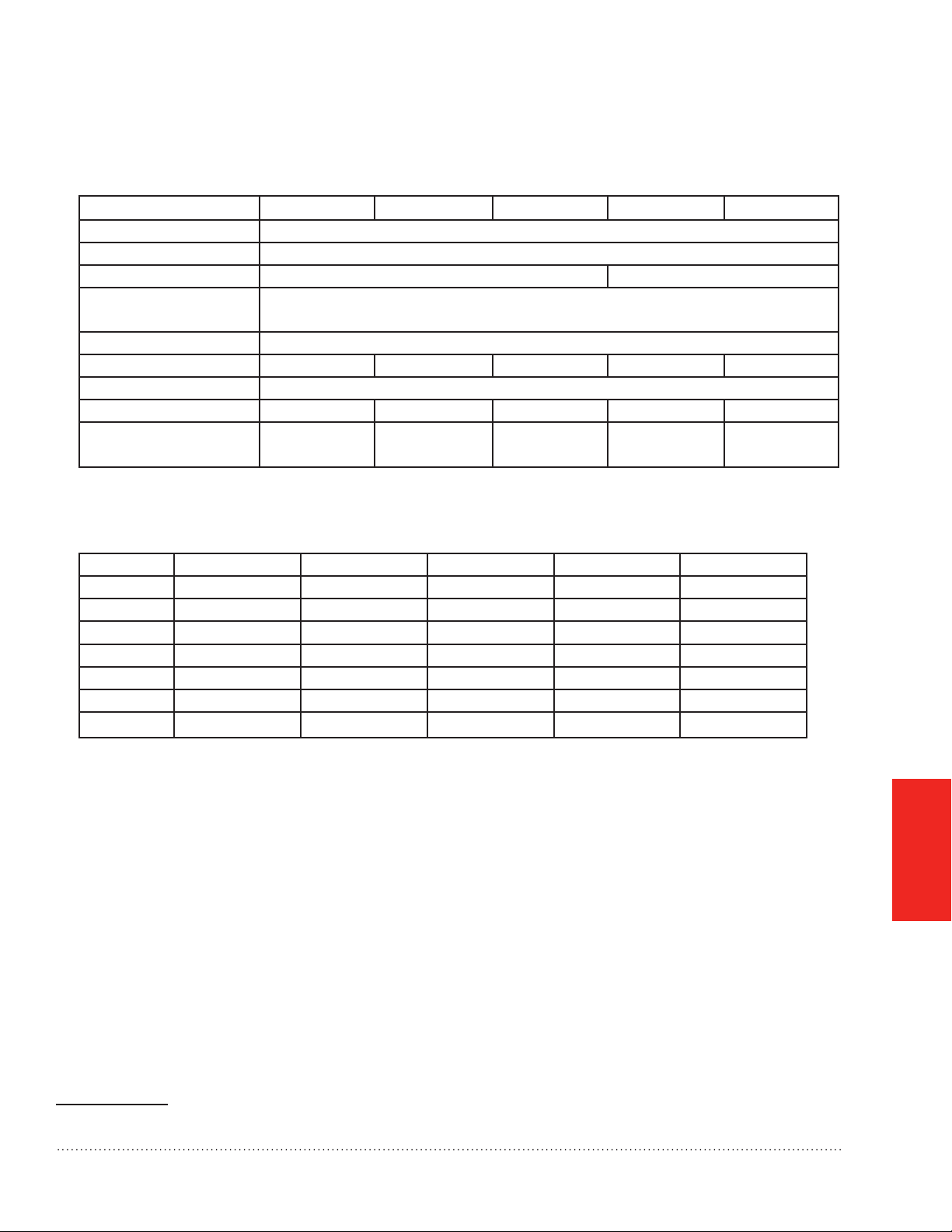
Table 2. Dimensions in inches and (mm).
A 18 5/8 (473) 22 1/8 (562) 25 5/8 (651) 18 3/8 (467) 21 7/8 (556)
B 15 3/8 (391) 18 7/8 (479) 22 3/8 (568) 15 1/8 (384) 18 5/8 (473)
C 13 1/8 (333) 13 1/8 (333) 13 1/8 (333) 11 1/8 (283) 11 1/8 (283)
D 17 5/8 (448) 21 1/8 (537) 24 5/8 (626) 17 1/2 (445) 21 (533)
E 19 7/8 (505) 19 7/8 (505) 19 7/8 (505) 22 1/8 (562) 22 1/8 (562)
F 22 1/4 (565) 22 1/4 (565) 22 1/4 (565) 25 1/4 (641) 25 1/4 (641)
G 11 1/4 (286) 11 1/4 (286) 11 1/4 (286) N/A N/A
Standards and Approvals
The air cleaner is tested and certied to the following:
• CSA 22.2 No. 187-09
• UL 900 (lter only)
NOTE: The Honeywell Enhanced Air Cleaner is CSA certied for shock and electrical re hazard only.
APPENDICES
1 See Fig. 21 on page 27 for dimensioned drawings.
TrueCLEAN™ Enhanced Air Cleaner 68-0308EFS—03
25
Page 28
Specications, Dimensions, and Approvals
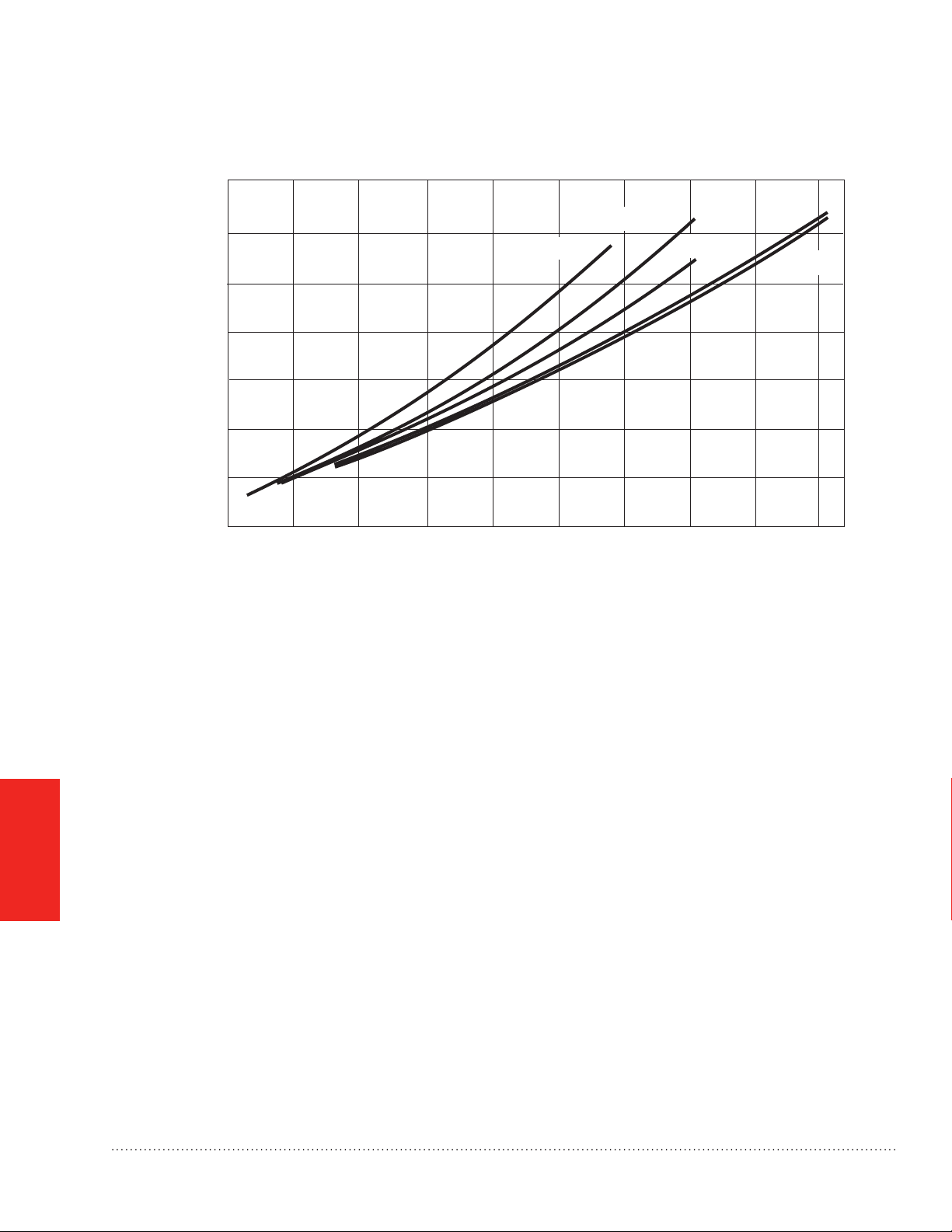
PRESSURE DROP CURVES
.35
.30
.25
.20
FILTER
PRESSURE
DROP IN
.15
H20
.10
.05
16 x 20 in.
(406 x 508 mm)
16 x 25 in.
(406 x 635 mm)
20 x 20 in.
(508 x 508 mm)
20 x 25 in.
(508 x 635 mm)
25 x 20 in.
(635 x 508 mm)
APPENDICES
0
200 400 600 800 1000 1200 1400 1600 1800 2000
FLOW RATE (CFM)
Fig. 20. Pressure Drop Curves
M32379
26
TrueCLEAN™ Enhanced Air Cleaner 68-0308EFS—03
Page 29
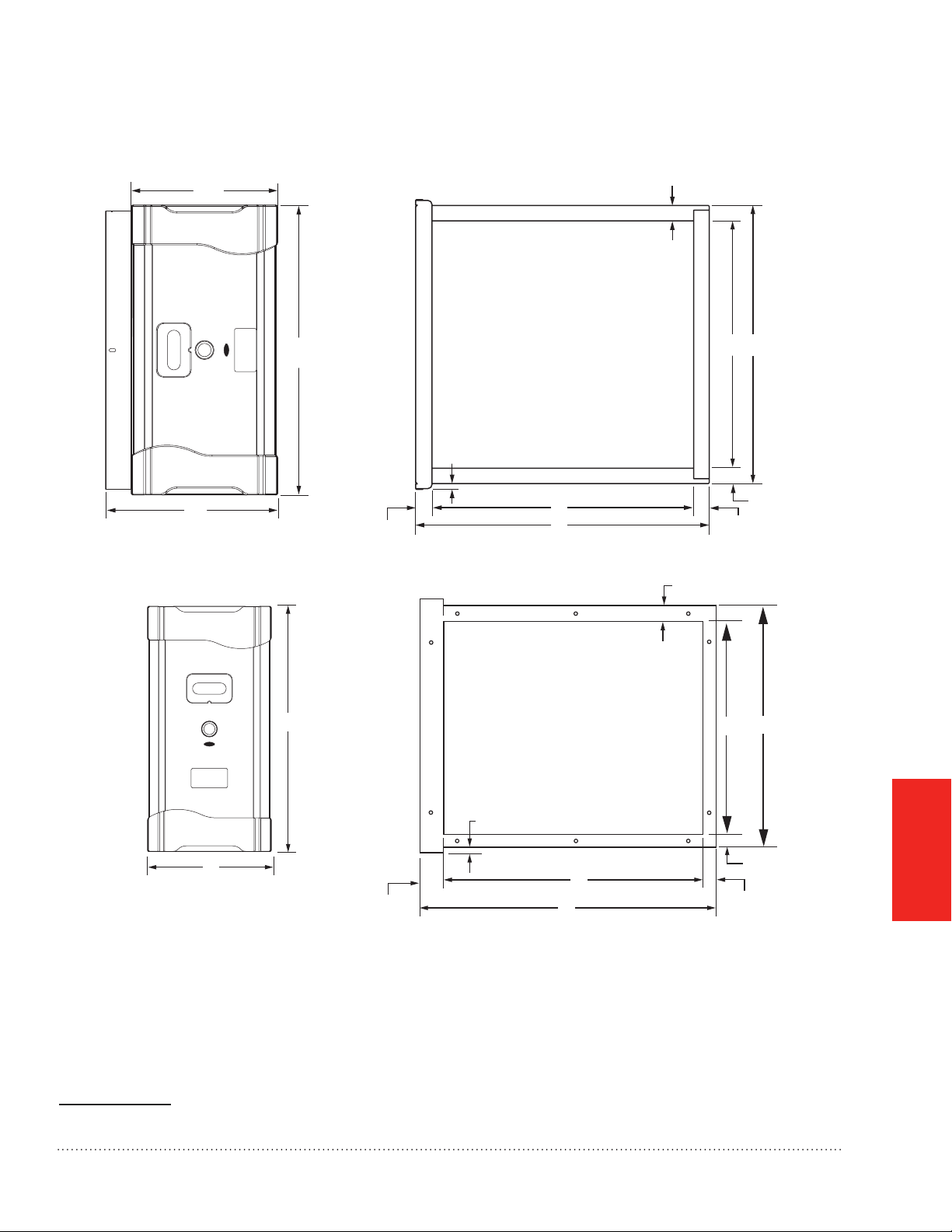
Specications, Dimensions, and Approvals
FH8000A
G
1-3/16 (30)
A
3/8 (9.5) TYPICAL TOP & BOTTOM
DB
C
1-1/2 (38)
FH8000F
E
F
1-3/16 (30)
1-3/16 (30)
1-3/16 (30)
A
C
Fig. 21. Dimensions in inches (mm).1
1 See Table 2 on page 25 for lettered dimensions.
1-15/16 (49)
7/16 (11) TYPICAL TOP AND BOTTOM
E
F
B
1-3/16 (30)
1-3/16 (30)
D
APPENDICES
M28917A
TrueCLEAN™ Enhanced Air Cleaner 68-0308EFS—03
27
Page 30

TrueCLEAN™ Parts List
FH8000F1625 FH8000F2025 FH8000A1620 FH8000A2020 FH8000A2520
A Door 50053268-006 50053268-007 50053268-008 50053268-009 50053268-010
B Filter FR8000F1625 FH8000F2025 FH8000A1620 FH8000A2020 FH8000A2520
C Enhancement Module 50053268-001 50053268-002 50053268-003 50053268-004 50053268-005
D Safety Screen 50053268-011 50053268-012 50053268-013 50053268-014 50053268-015
E Air Flow Sensor NA 50053268-018
F Power Cord & Accessories
(Installation Components)
50053268-016 50053268-017
A
A
APPENDICES
F
F
1
A
E
Door FH8000A.
1
Door FH8000F
2
Filter
Enhancement module
Safety screen
Air flow sensor (FH8000A)
E
Power Cord & Accessories (Installation Components FH8000A)
1
Power Cord & Accessories (Installation Components FH8000F)
2
2
A
1
F
2
F
M32380
28
TrueCLEAN™ Enhanced Air Cleaner 68-0308EFS—03
Page 31

5-Year Limited Warranty
Honeywell warrants this product to be free from defects in the workmanship or materials, under normal use
and service, for a period of ve (5) years from the date of purchase by the consumer. If at any time during the
warranty period the product is determined to be defective or malfunctions, Honeywell shall repair or replace it (at
Honeywell’s option).
If the product is defective,
(i) return it, with a bill of sale or other dated proof of purchase, to the place from which you purchased it; or
(ii) call Honeywell Customer Care at 1-800-468-1502. Customer Care will make the determination whether the
product should be returned to the following address: Honeywell Return Goods, Dock 4 MN10-3860, 1985 Douglas
Dr. N., Golden Valley, MN 55422, or whether a replacement product can be sent to you.
This warranty does not cover removal or reinstallation costs. This warranty shall not apply if it is shown by
Honeywell that the defect or malfunction was caused by damage which occurred while the product was in the
possession of a consumer.
Honeywell’s sole responsibility shall be to repair or replace the product within the terms stated above.
HONEYWELL SHALL NOT BE LIABLE FOR ANY LOSS OR DAMAGE OF ANY KIND, INCLUDING ANY
INCIDENTAL OR CONSEQUENTIAL DAMAGES RESULTING, DIRECTLY OR INDIRECTLY, FROM ANY
BREACH OF ANY WARRANTY, EXPRESS OR IMPLIED, OR ANY OTHER FAILURE OF THIS PRODUCT. Some
states do not allow the exclusion or limitation of incidental or consequential damages, so this limitation may not
apply to you.
THIS WARRANTY IS THE ONLY EXPRESS WARRANTY HONEYWELL MAKES ON THIS PRODUCT. THE
DURATION OF ANY IMPLIED WARRANTIES, INCLUDING THE WARRANTIES OF MERCHANTABILITY AND
FITNESS FOR A PARTICULAR PURPOSE, IS HEREBY LIMITED TO THE FIVE-YEAR DURATION OF THIS
WARRANTY. Some states do not allow limitations on how long an implied warranty lasts, so the above limitation
may not apply to you.
This warranty gives you specic legal rights, and you may have other rights which vary from state to state.
If you have any questions concerning this warranty, please write Honeywell Customer Relations, 1985 Douglas
Dr, Golden Valley, MN 55422 or call 1-800-468-1502. In Canada, write Retail Products ON15-02H, Honeywell
Limited/Honeywell Limitée, 35 Dynamic Drive, Toronto, Ontario M1V4Z9.
TrueCLEAN™ Enhanced Air Cleaner 68-0308EFS—03
APPENDICES
29
Page 32

Automation and Control Solutions
Honeywell International Inc.
1985 Douglas Drive North
Golden Valley, MN 55422
Honeywell Limited–Honeywell Limitée
35 Dynamic Drive
Toronto, Ontario M1V 4Z9
http://yourhome.honeywell.com
® U.S. Registered Trademark
© 2011 Honeywell International Inc.
68-0308EFS—03 M.S. Rev. 01-11
Printed in U.S.A.
Page 33

M28898
68-0308EFS-03
Épurateur d’air amélioré TrueCLEAN™
Dimensions : Unité de traitement de l’air 16x20, 20x20, 25x20 • Générateur d’air chaud 16x25 et 20x25
PROFESSIONAL INSTALLATION GUIDE.
GUIDE D’INSTALLATION PROFESSIONNELLE.
GUÍA DE INSTALACIÓN PROFESIONAL.
INCLUS DANS LA BOÎTE DE L’ÉPURATEUR D’AIR AMÉLIORÉ
1
A
F
2
A
1
G
I
J
ECB D
2
J
COMMENCER
POUR
MONTAGE
CÂBLAGE
FONCTIONNEMENT
ET REPARATION
K
H
Outils requis pour installer l’épurateur d’air
amélioré
Tournevis normal
Tournevis cruciforme
Cisailles à tôle
Perceuse
Produit d’étanchéité de gaine
Tableau des filtres de rechange
Épurateur d’air
amélioré
Unités de traitement
de l’air
Générateurs d’air
chaud à air pulsé
Modèle
Honeywell
FH8000A1620
FH8000A2020
FH8000A2520
FH8000F1625
FH8000F2025
Référence du
ltre de rechange
FR8000A1620
FR8000A2020
FR8000A2520
FR8000F1625
FR8000F2025
Porte FH8000A
1
A
Porte FH8000F
2
A
Armoire
Filtre
Module d’amélioration
Grille de sécurité
E
Ruban pour joints de gaine
F
Adaptateurs de gaine de retour
G
Adaptateurs de générateur d’air chaud
H
(FH8000F)
Capteur de débit d’air (FH8000A)
I
Organes d’installation (FH8000A)
1
J
Organes d’installation (FH8000F)
2
J
K
Notice d’installation
ANNEXES
Page 34

Page 35

Épurateur d’air amélioré TrueCLEAN™
POUR COMMENCER
Qu’attendre de votre épurateur d’air amélioré
TrueCLEAN™ Honeywell .....................................................2
Fonctionnement ..................................................................2
Considérations relatives à l’application ..............................3
Exigences d’installation importantes ...................................5
Sécurité personnelle ............................................................5
MONTAGE
Choix d’une méthode de montage .......................................6
Quel modèle d’épurateur d’air amélioré de
Honeywell possédez-vous? .................................................6
Montage de l’épurateur d’air amélioré FH8000A
Honeywell (Unité de traitement de l’air) ..............................7
Montage de l’épurateur d’air amélioré FH8000F
Honeywell (Générateur d’air chaud) .................................10
CÂBLAGE
Avant le câblage de l’épurateur d’air amélioré de
Honeywell ..........................................................................14
Câblage de l’épurateur d’air amélioré FH8000A
Honeywell (Unité de traitement de l’air) ............................15
Câblage de l’épurateur d’air amélioré FH8000F
Honeywell (Générateur d’air chaud) ..................................17
FONCTIONNEMENT ET RÉPARATION
Démarrage et fonctionnement ...........................................19
Vérication du fonctionnement
de l’épurateur d’air ............................................................19
Entretien ............................................................................20
Dépannage ........................................................................22
ANNEXES
Spécications, dimensions et homologations ..................24
Liste des pièces .................................................................28
Garantie .............................................................................29
COMMENCER
POUR
MONTAGE
CÂBLAGE
BESOIN D’AIDE? Pour obtenir de l’aide sur ce produit, prière de visiter le site
?
http://yourhome.honeywell.com
ou d’appeler le service d’assistance à la clientèle de Honeywell au 1-800-468-1502.
FONCTIONNEMENT
ET RÉPARATION
ANNEXES
Lire et conserver ces instructions.
® Marque de commerce déposée américaine. Brevets en instance. Copyright © 2010 Honeywell International Inc. Tous droits réservés.
Épurateur d’air amélioré TrueCLEAN™ 68-0308EFS—03
1
Page 36

POUR
COMMENCER
Qu’attendre de votre épurateur d’air amélioré TrueCLEAN™
Honeywell
Félicitations pour votre choix de l’épurateur d’air amélioré TrueCLEAN™ Honeywell pour votre système de
confort d’intérieur! L’épurateur d’air amélioré de Honeywell a fait ses preuves en matière de retrait et d’élimination
des bactéries et allergènes présents dans l’air, y compris des virus, bactéries et spores de moisissures de l’air
passant par le ltre. L’épurateur d’air amélioré de Honeywell est une pierre d’angle des solutions de confort
d’intérieur de Honeywell visant à fournir un air plus propre dans les résidences.
L’installateur doit considérer ces points avec le propriétaire et répondre à toute question avant de quitter le site
des travaux.
Lors de l’installation du produit...
1. Lire attentivement ces instructions. Le non-respect des instructions peut endommager le produit ou provoquer
une situation dangereuse.
2. Vérier les caractéristiques nominales indiquées dans les instructions et sur le produit pour s’assurer que le
produit correspond bien à l’application prévue.
3. L’installateur doit être un technicien expérimenté ayant reçu la formation adéquate.
4. Une fois l’installation terminée, vérier que le produit fonctionne comme indiqué dans ces instructions.
Fonctionnement
L’épurateur d’air amélioré TrueCLEAN™ de Honeywell assure une ltration extrêmement performante, tout en
éliminant les contaminants piégés, notamment les virus, bactéries et spores de moisissures. L’épurateur d’air
amélioré de Honeywell traite la totalité du ux d’air grâce à un processus de pointe à trois étapes.
Étape 1
Au cours de la première étape, les particules dans l’air sont électriquement chargées par un réseau de points
d’ionisation tandis qu’elles pénètrent dans l’épurateur d’air amélioré de Honeywell.
Étape 2
Au cours de l’étape 2, les particules chargées sont électriquement attirées et capturées dans la cartouche du ltre
à air, qui est situé dans un champ électrique.
Étape 3
Au cours de l’étape 3, les particules capturées sont éliminées par un courant électrique et un bombardement
d’ions.
2
Épurateur d’air amélioré TrueCLEAN™ 68-0308EFS—03
Page 37

Considérations relatives à l’application
L’épurateur d’air amélioré de Honeywell est conçu pour une utilisation dans la gaine d’air de retour des
systèmes de chauffage, refroidissement et ventilation à air forcé. Les modèles FH8000A1620, FH8000A2020 et
FH8000A2520 sont spéciquement conçus pour être utilisés par les systèmes équipés d’une unité de traitement
de l’air. Les modèles FH8000F1625 et FH8000F2025 sont spéciquement conçus pour une utilisation dans les
systèmes de générateurs d’air chaud à air pulsé. L’épurateur d’air amélioré de Honeywell est certié CSA pour les
chocs et les incendies électriques uniquement.
Climatisation
L’épurateur d’air amélioré de Honeywell doit être installé dans un système de sorte que la totalité de l’air de retour
y circule. Il doit être installé en amont de l’équipement de climatisation. Ceci permet de maintenir la propreté de
l’équipement et d’empêcher la condensation de se former dans l’épurateur d’air amélioré de Honeywell.
Humidicateurs
Un humidicateur à évaporation peut être monté en amont de l’épurateur d’air amélioré de Honeywell. Il est
préférable d’installer les humidicateurs à atomisation en aval de l’épurateur d’air amélioré de Honeywell pour
ne pas que les dépôts de sel de l’eau dure et les gouttes d’eau endommagent le ltre. Si un humidicateur à
atomisation doit être monté en amont de l’épurateur d’air amélioré de Honeywell, il doit être monté autant en
amont que possible (au moins 1,8 m [6 pi] recommandés), et un ltre pour générateur d’air chaud jetable standard
doit être monté entre l’humidicateur et l’épurateur d’air amélioré de Honeywell pour piéger les dépôts de sel de
l’eau dure et les gouttes d’eau.
COMMENCER
POUR
Transitions
Si les ouvertures de gaines d’air de retour et de ventilo-convecteur ne correspondent pas à la taille des
ouvertures de l’armoire de l’épurateur d’air amélioré de Honeywell, des transitions graduelles sont recommandées
pour réduire les turbulences de l’air et maximiser l’efcacité.
FH8000A – Une expansion de 20° (environ 4 po par pied de longueur) maximum doit être utilisée de chaque côté
du raccord de transition.
FH8000F – Une expansion de 45° (environ 8,5 po par pied de longueur) maximum doit être utilisée de chaque
côté du raccord de transition.
Aubes directrices
Si l’épurateur d’air amélioré de Honeywell est installé adjacent à un coude de gaine de 90°, des aubes directrices
doivent être installées dans la gaine pour améliorer la distribution de l’air sur la surface de l’épurateur d’air
amélioré de Honeywell.
Épurateur d’air amélioré TrueCLEAN™ 68-0308EFS—03
3
Page 38

Considérations relatives à l’application
Alimentation électrique / Interrupteur de débit d’air
L’épurateur d’air amélioré de Honeywell ne doit être mis en marche que lorsqu’un débit d’air est présent.
POUR
COMMENCER
FH8000A – Ces modèles sont conçus pour une utilisation avec une unité de traitement de l’air et sont munis d’un
interrupteur de débit d’air (voir Fig. 1), qui fournit une alimentation uniquement lorsque le ventilateur de l’unité de
traitement de l’air est en marche. Ces modèles sont conçus pour être alimentés par une source d’alimentation à
phase unique de 208 à 230 V c.a.
Fig. 1. Interrupteur de débit d’air.
FH8000F – Les bornes de l’épurateur d’air électronique du régulateur du générateur d’air chaud alimentent l’unité
uniquement lorsque la soufflante du générateur d’air chaud fonctionne. Ces modèles sont conçus pour être
alimentés à partir des bornes de l’épurateur d’air électronique sur le tableau de contrôle de générateur d’air
chaud. Si les bornes de l’épurateur à air électronique ne sont pas disponibles, un autre mécanisme de détection
du débit d’air, tel que le pressostat différentiel 50027910-001 de Honeywell, doit être utilisé pour garantir que
l’épurateur à air amélioré de Honeywell est uniquement alimenté lorsqu’un débit d’air est présent. Contacter le
distributeur Honeywell local pour obtenir des informations sur d’autres solutions.
4
Épurateur d’air amélioré TrueCLEAN™ 68-0308EFS—03
Page 39

Exigences d’installation importantes
Le non-respect de ces exigences annulera la garantie, nuira à l’installation et entraînera des appels
de service injustiés.
Sécurité personnelle
• Porter des lunettes de protection lors de l’installation de l’unité.
• Veiller à ne pas entailler la conduite électrique ou de climatisation.
• Respecter les normes de sécurité professionnelles et les codes de plomberie et d’électricité et d’installations
mécaniques.
Avant le montage
• En consultant la gure sur le couvercle et les listes dans le couvercle intérieur, s’assurer que tous les
composants requis pour le modèle d’épurateur d’air amélioré de Honeywell et tous les outils pour l’installation
sont présents.
• S’assurer que la direction du débit d’air par l’épurateur d’air amélioré de Honeywell correspond aux èches sur
la face du ltre. Les èches doivent pointer vers l’équipement de chauffage/refroidissement. La porte peut être
tournée de 180° pour accommoder l’orientation de l’armoire.
• L’emplacement de l’épurateur d’air amélioré de Honeywell doit être facilement accessible. Un dégagement
sufsant doit être assuré pour les remplacements périodiques du ltre.
COMMENCER
POUR
Pour le remplacement d’un ancien épurateur d’air
Si l’épurateur d’air amélioré de Honeywell n’est pas identique au ltre à air existant en matière de taille et de
forme, avant d’effectuer une installation de modernisation, il peut être nécessaire d’ajouter des transitions de
gaine pour assurer un débit d’air régulier.
Filtres de rechange
Tableau des filtres de rechange
Épurateur d’air
amélioré
Unités de traitement
de l’air
Générateurs d’air
chaud à air pulsé
Modèle
Honeywell
FH8000A1620
FH8000A2020
FH8000A2520
FH8000F1625
FH8000F2025
Référence du ltre de
rechange
FR8000A1620
FR8000A2020
FR8000A2520
FR8000F1625
FR8000F2025
Épurateur d’air amélioré TrueCLEAN™ 68-0308EFS—03
5
Page 40

Choix d’une méthode de montage
L’épurateur d’air amélioré de Honeywell est disponible en deux conceptions. L’une conçue pour les unités de
traitement de l’air, et l’autre pour les générateurs d’air chauds. Suivre la notice d’installation correspondant au
modèle d’épurateur d’air en question :
Quel modèle d’épurateur d’air amélioré de Honeywell possédez-vous?
MONTAGE
Modèles FH8000A pour unités de traitement
de l’air :
Ces modèles s’installent en amont de l’unité de
traitement de l’air. Ceci permet de maintenir la propreté
de l’unité de traitement de l’air.
M28900
Fig. 2. Épurateur d’air amélioré de Honeywell modèles
FH8000A.
Modèles FH8000F pour générateur d’air chaud :
Ces modèles s’installent en amont du générateur
d’air chaud et en amont du serpentin évaporateur
du système de climatisation. Fig. 3. Épurateur d’air
amélioré de Honeywell modèles FH8000F.
M28901
Fig. 3. Épurateur d’air amélioré de Honeywell
modèles FH8000F
Avant de commencer le montage :
J’ai conrmé que les codes locaux relatifs aux pratiques de câblage électrique sont respectés.
J’ai choisi un emplacement d’installation qui répond aux exigences des pages 3 à 5.
REMARQUE : Pour monter l’épurateur d’air amélioré de Honeywell FH8000A (Unité de traitement de l’air), aller
à la page 7.
REMARQUE : Pour monter l’épurateur d’air amélioré de Honeywell FH8000F (Générateur d’air chaud), aller à la
page 10.
6
Épurateur d’air amélioré TrueCLEAN™ 68-0308EFS—03
Page 41
Montage de l’épurateur d’air amélioré FH8000A Honeywell
(Unité de traitement de l’air)
REMARQUE : Pour monter un modèle FH8000F, aller à la page 10.
MISE EN GARDE : Risque de blessures.
Le non-respect de cette mise en garde peut causer des blessures. Les pièces en tôle peuvent avoir
des rebords coupants. Faire preuve de prudence et porter des vêtements de protection, des protections
oculaires et des gants appropriés lors de manipulations des pièces.
ÉTAPE 1 : Identier l’emplacement et l’orientation de montage
a. Identier un emplacement de montage de l’épurateur d’air amélioré de Honeywell dans la gaine d’air de retour
(voir Fig. 4).
b. S’assurer que la direction du débit d’air par l’épurateur d’air amélioré de Honeywell correspond aux èches
sur la face du ltre. La porte de l’épurateur d’air amélioré de Honeywell peut être tournée de 180° pour
accommoder l’orientation de l’armoire.
c. L’emplacement de l’unité doit être facilement accessible. Un dégagement sufsant doit être fourni pour pouvoir
retirer la porte et le ltre pour les remplacements périodiques du ltre à air.
MONTAGE
DÉBIT
D’AIR
DÉBIT D’AIR
Débit descendant Horizontal Débit ascendant
DÉBIT
D’AIR
MF28902
Fig. 4. Orientation de l’armoire pour les modèles FH8000A.
Épurateur d’air amélioré TrueCLEAN™ 68-0308EFS—03
7
Page 42

MONTAGE
Montage de l’épurateur d’air amélioré FH8000A Honeywell
(Unité de traitement de l’air)
ÉTAPE 2 : Montage de l’armoire
AVERTISSEMENT : Risque d’électrocution et de dégâts de l’unité.
Le non-respect de cette mise en garde peut causer des blessures ou le décès.
Seul un technicien d’entretien formé et expérimenté doit installer l’épurateur d’air amélioré de Honeywell.
Une vérication intégrale de l’installation de l’unité doit être terminée avant de faire fonctionner l’unité. Avant
d’effectuer l’installation, l’entretien ou des réparations sur l’unité, couper toute l’alimentation vers l’unité.
1. Avant d’installer ou de réparer le système, toujours couper l’alimentation principale vers le système. Il peut
y avoir plus d’un sectionneur.
2. Les armoires supportent un poids maximum de 181 kg (400 lb) lorsqu’elles sont installées sous un
générateur d’air chaud ou une unité de traitement de l’air verticale. Lorsque le générateur d’air chaud est
installé sur l’armoire, ne pas le laisser tomber en position. Placer correctement le générateur d’air chaud sur
l’armoire pour éviter qu’un coin ne glisse et n’endommage l’armoire ou ses composants.
a. Couper l’alimentation vers le système de chauffage et de refroidissement.
b. Retirer le ltre à air existant de l’unité de traitement de l’air et le jeter. Une pression statique excessive du
système peut être causée si l’épurateur d’air amélioré de Honeywell est utilisé avec d’autres dispositifs de
ltration.
c. Retirer le ltre et le module d’amélioration de l’armoire de l’épurateur d’air amélioré de Honeywell.
d. Placer l’armoire entre l’unité de traitement de l’air et la gaine d’air de retour (voir Fig. 4 page 7 et Fig. 5). Une
gaine de transition peut être requise.
ADAPTATEURS
DE GAINE DE
RETOUR (4)
MONTAGE VERTICAL DE L’ARMOIRE
MONTAGE HORIZONTAL DE L’ARMOIRE
ADAPTATEURS DE
GAINE DE RETOUR (4)
MF28903
Fig. 5. Orientation des modèles FH8000A pour les unités de traitement de l’air.
REMARQUES :
1. Les vis de l’armoire de l’unité de traitement de l’air maintenant le plateau du ltre doivent être utilisées
pour attacher l’armoire de l’épurateur d’air amélioré.
2. Le ruban de joint entre l’unité de traitement de l’air et l’armoire de l’épurateur d’air amélioré de
Honeywell est déjà installé en usine.
3. Les trous de montage sont fournis pour la xation de l’unité de traitement de l’air.
8
Épurateur d’air amélioré TrueCLEAN™ 68-0308EFS—03
Page 43

Montage de l’épurateur d’air amélioré FH8000A Honeywell
(Unité de traitement de l’air)
e. Utiliser les adaptateurs de gaine de retour fournis pour attacher les gaines de retour (voir Fig. 6).
f. Appliquer du ruban ou de l’enduit sur les jointures après avoir attaché l’armoire de l’épurateur d’air amélioré de
Honeywell.
ADAPTATEURS DE
REMARQUE :
GLISSER LES CALES EN S SUR
LES BRIDES SUR LE
CÔTÉ DE LA GAINE DE RETOUR.
GAINE DE RETOUR
MONTAGE
MF28904
Fig. 6. Utilisation des adaptateurs de gaine de retour pour les modèles FH8000A.
Avant de procéder au câblage page 14 :
J’ai monté et xé l’armoire de l’épurateur d’air amélioré de Honeywell à la gaine conformément aux
instructions.
Le montage des modèles FH8000A est terminé. Passer à la page 14.
Épurateur d’air amélioré TrueCLEAN™ 68-0308EFS—03
9
Page 44

MONTAGE
Montage de l’épurateur d’air amélioré FH8000F Honeywell
(Générateur d’air chaud)
REMARQUE : Pour monter un modèle FH8000A revenir à la page 7.
MISE EN GARDE : Risque de blessures.
Le non-respect de cette mise en garde peut causer des blessures. Les pièces en tôle peuvent avoir des
rebords coupants. Faire preuve de prudence et porter des vêtements de protection et des gants appropriés
lors de manipulations des pièces.
ÉTAPE 1 : Identier l’emplacement et l’orientation de montage
a. Identier un emplacement de montage de l’épurateur d’air amélioré de Honeywell dans la gaine d’air de retour.
Voir Fig. 7 et Fig. 8 page 11.
b. S’assurer que la direction du débit d’air par l’épurateur d’air amélioré de Honeywell correspond aux èches sur
la face de la cartouche du ltre à air. La porte de l’épurateur d’air amélioré de Honeywell peut être tournée de
180° pour accommoder l’orientation de l’armoire.
c. L’emplacement de l’unité doit être facilement accessible. Un dégagement sufsant doit être assuré pour retirer
la porte et remplacer le ltre.
DÉBIT
D’AIR
REMARQUE :
LE MONTAGE DE CE CÔTÉ
NÉCESSITE QUE L’ARMOIRE
SOIT TOURNÉE DE 180° POUR
GARANTIR UN DÉBIT D’AIR CORRECT.
GÉNÉRATEUR D’AIR CHAUD À DÉBIT
ASCENDANT AVEC RETOUR LATÉRAL
DÉBIT D’AIR
APPLICATION HORIZONTALE
Fig. 7. Orientation de l’armoire pour les modèles FH8000F.
DÉBIT
GÉNÉRATEUR D’AIR CHAUD À DÉBIT
ASCENDANT AVEC MONTAGE INFÉRIEUR
D’AIR
DÉBIT
D’AIR
GÉNÉRATEUR D’AIR CHAUD À DÉBIT
DESCENDANT AVEC MONTAGE INFÉRIEUR
MF28905
10
Épurateur d’air amélioré TrueCLEAN™ 68-0308EFS—03
Page 45

Montage de l’épurateur d’air amélioré FH8000F Honeywell
DÉBIT
(Générateur d’air chaud)
REMARQUE : LORS DE LA TRANSITION ENTRE DEUX COMPOSANTS DE TAILLE DIFFÉRENTE (GÉNÉRATEUR D’AIR CHAUD ET UNITÉ DE TRAITEMENT
DE L’AIR), L’ANGLE DE TRANSITION MINIMUM AU NIVEAU DU COMPOSANT LE PLUS GRAND NE DOIT PAS ÊTRE INFÉRIEUR À 45°.
DÉBIT D’AIR
GÉNÉRATEUR D’AIR CHAUD À
DESCENDANT DE 14 PO
AVEC MONTAGE SUPÉRIEUR
DÉBIT D’AIR
GÉNÉRATEUR D’AIR CHAUD À
DÉBIT DESCENDANT DE 24 PO
AVEC MONTAGE SUPÉRIEUR
DÉBIT D’AIR
DÉBIT
D’AIR
GÉNÉRATEUR D’AIR CHAUD À
DÉBIT ASCENDANT DE 14 PO
AVEC MONTAGE INFÉRIEUR
DÉBIT
D’AIR
GÉNÉRATEUR D’AIR CHAUD À
DÉBIT ASCENDANT DE 24 PO
SUR SUPPORT AVEC
MONTAGE INFÉRIEUR
GÉNÉRATEUR D’AIR CHAUD HORIZONTAL
DE 14 PO AVEC MONTAGE LATÉRAL
DÉBIT D’AIR
GÉNÉRATEUR D’AIR CHAUD
HORIZONTAL DE 24 PO
GÉNÉRATEUR D’AIR CHAUD À
DÉBIT
D’AIR
GÉNÉRATEUR D’AIR CHAUD À
DÉBIT ASCENDANT AVEC PLÉNUM
Fig. 8. Orientation de l’armoire pour les modèles FH8000F avec transition.
DÉBIT
D’AIR
DÉBIT ASCENDANT
PLENUM
BOX
MONTAGE
MF28906
Épurateur d’air amélioré TrueCLEAN™ 68-0308EFS—03
11
Page 46

MONTAGE
7
Montage de l’épurateur d’air amélioré FH8000F Honeywell
(Générateur d’air chaud)
ÉTAPE 2 : Montage de l’armoire
AVERTISSEMENT : Risque d’électrocution et de dégâts de l’unité.
Le non-respect de cette mise en garde peut causer des blessures ou le décès.
Seul un technicien d’entretien formé et expérimenté doit installer l’épurateur d’air amélioré de Honeywell.
Une vérication intégrale de l’installation de l’unité doit être terminée avant de faire fonctionner l’unité. Avant
d’effectuer l’installation, l’entretien ou des réparations sur l’unité, couper toute l’alimentation vers l’unité.
1. Avant d’installer ou de réparer le système, toujours couper l’alimentation principale vers le système. Il
peut y avoir plus d’un sectionneur.
2. Les armoires supportent un poids maximum de 181 kg (400 livres) lorsqu’elles sont installées sous un
générateur d’air chaud ou une unité de traitement de l’air verticale. Lorsque le générateur d’air chaud est
installé sur l’armoire, ne pas le laisser tomber en position. Placer correctement le générateur d’air chaud sur
l’armoire pour éviter qu’un coin ne glisse et n’endommage l’armoire ou ses composants.
a. Couper l’alimentation vers le système de chauffage et de refroidissement.
b. Retirer le ltre du générateur d’air chaud existant et le jeter. Une pression statique excessive peut être causée
si l’épurateur d’air amélioré de Honeywell est utilisé avec d’autres dispositifs de ltration.
c. Retirer le ltre et le module d’amélioration de l’armoire de l’épurateur d’air amélioré de Honeywell.
d. Placer l’armoire entre le générateur d’air chaud et la gaine d’air de retour (voir Fig. 7 page 10, Fig. 8 page 11,
Fig. 9 et Fig. 10 page 13). Une gaine de transition peut être requise.
e. Des adaptateurs de générateur d’air chaud sont inclus pour la commodité de l’installateur. Ils sont conçus pour
les installations à montage inférieur ou supérieur (voir Fig. 9).
GÉNÉRATEUR D’AIR CHAUD
ADAPTATEURS DE
DÉBIT D’AIR
DÉBIT D’AIR
MF2890
Fig. 9. Utilisation d’adaptateurs de générateur d’air chaud.
12
Épurateur d’air amélioré TrueCLEAN™ 68-0308EFS—03
Page 47

Montage de l’épurateur d’air amélioré FH8000F Honeywell
(Générateur d’air chaud)
f. Des adaptateurs de gaine d’air de retour sont inclus pour la commodité de l’installateur. Ils doivent être utilisés
pour connecter le côté débit ascendant de l’armoire de l’épurateur d’air amélioré de Honeywell à la gaine d’air
de retour (voir Fig. 10).
g. Installer de l’isolant adhésif entre le générateur d’air chaud et l’armoire de l’épurateur d’air amélioré de
Honeywell.
h. Des trous de montage sont fournis pour la xation des gaines et du générateur d’air chaud.
i. Appliquer du ruban ou de l’enduit sur les jointures après avoir attaché l’armoire de l’épurateur d’air amélioré de
Honeywell.
REMARQUE : GLISSER LES CALES
EN S SUR LES BRIDES SUR LE
CÔTÉ DE LA GAINE DE RETOUR.
MONTAGE
MF28897
Fig. 10. Utilisation d’adaptateurs de gaine de retour.
Avant de procéder au câblage page 14 :
J’ai monté et xé l’armoire de l’épurateur d’air amélioré de Honeywell à la gaine conformément aux
instructions.
Le montage des modèles FH8000F est terminé. Passer à la page 14.
Épurateur d’air amélioré TrueCLEAN™ 68-0308EFS—03
13
Page 48

Avant le câblage de l’épurateur d’air amélioré de Honeywell
AVERTISSEMENT : Risque d’électrocution.
S’assurer que l’épurateur d’air amélioré de Honeywell n’est pas branché avant de
commencer le câblage.
Le non-respect de cette mise en garde peut causer des blessures ou le décès.
Avant d’installer ou de réparer le système, toujours couper l’alimentation principale vers
le système. Il peut y avoir plus d’un sectionneur.
Avant le câblage de l’épurateur d’air amélioré de Honeywell :
J’ai compris tous les codes et règlements de câblage en vigueur et je les appliquerai.
CÂBLAGE
REMARQUE : Pour le câblage des modèles FH8000A, passer à la page 15.
REMARQUE : Pour le câblage des modèles FH8000F, passer à la page 17.
14
Épurateur d’air amélioré TrueCLEAN™ 68-0308EFS—03
Page 49

Câblage de l’épurateur d’air amélioré FH8000A Honeywell (Unité
de traitement de l’air)
ÉTAPE 1 : Câblage de l’épurateur d’air amélioré FH8000A Honeywell (Unité de traitement de l’air)
a. S’assurer que l’alimentation est coupée du système de chauffage et de refroidissement.
b. Mettre l’interrupteur d’alimentation de l’épurateur d’air amélioré de Honeywell sur arrêt.
c. Brancher le cordon d’alimentation et le cordon de l’interrupteur de débit d’air dans leurs connecteurs
d’alimentation (voir Fig. 11).
d. Attacher le l de masse du cordon d’alimentation à la borne de masse de l’armoire en utilisant la vis fournie
dans la borne de masse (voir la Fig. 11).
CÂBLE D’INTERRUPTEUR
DE DÉBIT D’AIR INSTALLÉ
Fig. 11. Installation du câble de l’interrupteur de débit d’air et du câble d’alimentation.
CORDON D’ALIMENTATION INSTALLÉ
ET FIL DE MASSE ATTACHÉ À LA BORNE
MF31365
CÂBLAGE
REMARQUES :
1. Le cordon d’alimentation peut être acheminé d’un côté ou de l’autre de l’armoire. Selon le besoin, utiliser
les attaches mono-usage pour xer le cordon sur le côté du bloc d’alimentation.
2. Le connecteur de câble et les plaques de blocage doivent être retirées et réinstallées si le cordon est
réacheminé. Les vis du collier du connecteur de câble doivent être serrées à un couple de 9 po-lb.
3. L’épurateur d’air amélioré de Honeywell pour unité de traitement de l’air doit être alimenté à 208-230 V
c.a. à 60 Hz.
4. L’épurateur d’air amélioré de Honeywell ne doit être mis en marche que lorsqu’un débit d’air est présent.
Un interrupteur de débit d’air est installé en usine. Voir Fig. 1 page 4 et Fig. 14 page 16. Pour contourner
le capteur de débit d’air pour le dépannage, utiliser la prise du cavalier de dérivation spécial (voir Fig.
12) inclus dans le sac des pièces. Avec le cavalier de dérivation installé, l’épurateur d’air fonctionnera en
permanence lorsque connecté à l’alimentation secteur. Le cavalier de dérivation ne doit pas être utilisé
pour le fonctionnement normal.
e. Attacher les bornes de connexion rapide aux ls du connecteur d’alimentation à fusible (dans le sac de pièces
attaché au cordon) et brancher sur l’alimentation d’arrivée. Les bornes ont une polarité neutre et peuvent être
connectées dans l’une ou l’autre polarité. Attacher l’anneau de masse à la masse du châssis de l’unité de
traitement de l’air (voir Fig. 13 page 16).
Fig. 12. Fiche de cavalier de dérivation de capteur de débit d’air installé.
Épurateur d’air amélioré TrueCLEAN™ 68-0308EFS—03
M28910
15
Page 50

Câblage de l’épurateur d’air amélioré FH8000A Honeywell (Unité
FILS DE CONNECTEUR D’ALIMENTATION
CORDON DU
de traitement de l’air)
CÂBLAGE
PURIFICATEUR
D’AIR
CONNECTEUR DE CÂBLE POUR
FIXER LE CORDON D’ALIMENTATION
À L’ARMOIRE DE L’UNITÉ DE TRAITEMENT DE L’AIR
À FUSIBLE DES ORGANES D’INSTALLATION
(DANS SAC ATTACHÉ AU CORDON)
FUSIBLES EN LIGNE DE 5 A
MASSE :
ATTA CHER À LA MASSE DE
L’UNITÉ DE TRAITEMENT DE L’AIR (CHÂSSIS)
VERS RACCORD D’ALIMENTATION DE
L’UNITÉ DE TRAITEMENT DE L’AIR
Fig. 13. Masse du châssis de l’unité de traitement de l’air amélioré Honeywell.
CAPTEUR DE
DÉBIT D’AIR
VERS ALIMENTATION L2
VERS ALIMENTATION L1
MF28911
1) GLISSER LES LANGUETTES DU CAPTEUR
DE DÉBIT DANS LE SUPPORT
2) FAIRE TOURNER LE CAPTEUR DE DÉBIT
ET L’ATTA CHER DANS LE SUPPORT
MF28912
Fig. 14. Installation de l’interrupteur de débit d’air.
Avant de passer au Démarrage et fonctionnement page 19 :
J’ai branché l’épurateur d’air amélioré de Honeywell conformément aux instructions.
Le câblage des modèles FH8000A est terminé. Passer à la page 19.
16
Épurateur d’air amélioré TrueCLEAN™ 68-0308EFS—03
Page 51

Câblage de l’épurateur d’air amélioré FH8000F Honeywell
CORDON D’ALIMENTATION
(Générateur d’air chaud)
ÉTAPE 1 : Câblage de l’épurateur d’air amélioré FH8000F Honeywell (Générateur d’air chaud)
a. S’assurer que l’alimentation est coupée du système de chauffage et de refroidissement.
b. Mettre l’interrupteur d’alimentation de l’épurateur d’air amélioré de Honeywell sur arrêt.
c. Brancher le cordon d’alimentation au raccord d’alimentation (voir Fig. 15).
d. Attacher le l de masse du cordon d’alimentation à la borne de masse de l’armoire en utilisant la vis fournie
dans la borne de masse (voir la Fig. 15).
VERS BORNES DE L’ÉPURATEUR
À AIR ÉLECTRONIQUE
UTILISER LE RACCORD DE CÂBLE
POUR FIXER LE CORDON
D’ALIMENTATION À L’ARMOIRE
RACCORD
D’ALIMENTATION
ALIMENTATION
UTILISER LES ATTACHES POUR
FIXER LE CORDON AU
BOÎTIER D’ALIMENTATION
AUTRE ORIFICE DE PASSAGE
DU CORDON D’ALIMENTATION
RACCORD
D’ALIMENTATION
CORDON D’ALIMENTATION
FIL DE MASSE DU
CORDON
D’ALIMENTATION
FIL DE MASSE
À ATTACHER
À L’ARMOIRE
(VOIR DÉTAIL A)
CÂBLAGE
EXEMPLE DE TABLEAU DE
DÉTAIL A
BORNE EAC-2
CONTRÔLE DE GÉNÉRATEUR D’AIR CHAUD
ON
OFF
W2
1 2 3
LHT
OFF
Y1 DHUMG COM
DLY
24V
WW1Y/Y2R
HI HEAT
LO HEAT
FUSE 3-AMP
A
T
T
S
SEC-1 SEC-2
U
D
S
E
C
L
O
E
D
EAC-2
BLW
SPARE-1SPARE-2
TEST/TWIN
HUM
0.5-AMP024 VAC
NEUTRAL-L2
COOL
ACRDJ
UTILISER LES BORNES
PLT
POUR BRANCHER LES FILS
DU CORDON
D’ALIMENTATION
AUX BORNES EAC-1, EAC-2
ET DE MASSE DU
GÉNÉRATEUR D’AIR CHAUD
PL1
1
BHT/CLRRWLBROL/IHB
1-AMP@115 VAC
EAC-1 PR-1
IDR
L1
BORNE EAC-1
IHI/LOR
HSIR
IDM
1
PL2
HSI HI LO
MF31366
Fig. 15. Connexions électriques.
e. Acheminer le cordon par l’orice d’armoire le plus proche et protéger avec le connecteur de câble fourni. Des
attaches mono-usage sont fournies pour attacher le cordon sur le côté du bloc d’alimentation.
Épurateur d’air amélioré TrueCLEAN™ 68-0308EFS—03
17
Page 52

Câblage de l’épurateur d’air amélioré FH8000F Honeywell
(Générateur d’air chaud)
f. Attacher les bornes à connexion rapide aux cosses ouvertes EAC-1 et EAC-2, qui ont une polarité neutre.
g. Attacher l’anneau de masse à la masse du châssis du générateur d’air chaud.
REMARQUE : L’épurateur d’air amélioré de Honeywell FH8000F doit être alimenté à 120 V c.a. à 60 Hz.
REMARQUE : L’épurateur d’air amélioré de Honeywell ne doit être mis en marche que lorsqu’un débit d’air est
présent. Les cosses ouvertes EAC du régulateur du générateur d’air chaud ne fournissent l’électricité que
lorsque la soufante du générateur d’air chaud fonctionne. Si des raccords pour l’épurateur à air électronique
ne sont pas disponibles, un autre mécanisme de détection du débit d’air, tel que le pressostat différentiel
50027910-001 de Honeywell, doit être utilisé pour garantir que l’épurateur à air amélioré de Honeywell est
uniquement alimenté lorsqu’un débit d’air est présent. Contacter le distributeur Honeywell local pour obtenir des
informations sur d’autres capteurs de débit d’air.
CÂBLAGE
Avant de passer au Démarrage et fonctionnement page 19 :
J’ai branché l’épurateur d’air amélioré de Honeywell conformément aux instructions.
Le câblage des modèles FH8000F est terminé. Passer à la page 19.
18
Épurateur d’air amélioré TrueCLEAN™ 68-0308EFS—03
Page 53

Démarrage et fonctionnement
MODÈLE FH8000A MODÈLE FH8000F
Vérication du fonctionnement d’épurateur d’air
AVERTISSEMENT : Risque d’électrocution.
Le non-respect de cette mise en garde peut causer des blessures ou le décès.
Avant d’installer ou de réparer le système, toujours couper l’alimentation principale vers le système. Il peut y
avoir plus d’un sectionneur.
a. Attacher la porte de l’épurateur d’air amélioré de Honeywell à l’armoire. Un aimant dans la porte (voir Fig. 16)
est utilisé pour activer un interrupteur de sécurité dans l’alimentation lorsque la porte est installée. L’électricité
n’active pas l’épurateur d’air à moins que l’interrupteur de sécurité soit activé.
AIMENT DE L’INTERRUPTEUR DE PORTE
MF28914
Fig. 16. Aimant de l’interrupteur de la porte.
b. Mettre le système de climatisation en marche et régler le thermostat pour activer le ventilateur du système.
c. Mettre l’interrupteur d’alimentation de l’épurateur d’air amélioré de Honeywell sur marche.
d. Le voyant d’alimentation sous l’interrupteur d’alimentation de l’épurateur d’air amélioré de Honeywell s’allume
(voir Fig. 17).
VOYANT
D’ALIMENTATION
Fig. 17. Voyant d’alimentation.
MF28915A
e. S’assurer que le voyant s’éteint lorsque l’interrupteur d’alimentation de l’épurateur d’air amélioré de Honeywell
est sur arrêt, lorsque la soufante s’éteint, ou lorsque l’alimentation du système de climatisation est coupée.
REMARQUE : Lors de la mise sous tension des modèles FH8000A, le voyant s’allume pendant environ 5
secondes, et si aucun débit n’est détecté, il s’éteint. Si aucune cartouche de ltre à air n’est détectée,
le capteur de débit détecte cet état et éteint l’épurateur d’air amélioré de Honeywell après environ 7
secondes.
FONCTIONNEMENT
ET RÉPARATION
Épurateur d’air amélioré TrueCLEAN™ 68-0308EFS—03
19
Page 54

Entretien
L’épurateur d’air amélioré de Honeywell est conçu pour nécessiter un entretien minimal. L’entretien se limite au
remplacement du ltre et à l’inspection périodique/nettoyage à la brosse du réseau d’ionisation. La fréquence
de remplacement de la cartouche du ltre à air et de nettoyage du réseau d’ionisation peut dépendre de la
conception des gaines et des conditions environnementales locales.
Pour remplacer la cartouche du ltre à air, effectuer les étapes suivantes :
1. Éteindre le système de chauffage et de refroidissement.
AVERTISSEMENT : Risque d’électrocution.
Le non-respect de cette mise en garde peut causer des blessures ou le décès.
Avant d’installer ou de réparer le système, toujours couper l’alimentation principale vers le système. Il peut y
avoir plus d’un sectionneur.
2. Mettre l’interrupteur de l’épurateur d’air amélioré de Honeywell sur arrêt.
3. Retirer la porte de l’épurateur d’air amélioré de Honeywell.
4. Faire glisser l’ancien ltre et le jeter.
5. Installer le ltre neuf.
ET RÉPARATION
FONCTIONNEMENT
REMARQUE : Remplacer le ltre au moins chaque année, et plus souvent si nécessaire.
6. Replacer la porte de l’épurateur d’air amélioré de Honeywell.
7. Mettre l’interrupteur de l’épurateur d’air amélioré de Honeywell sur marche.
8. Mettre le système de chauffage et de refroidissement en marche.
20
Fig. 18 : S’assurer que les èches du ltre pointent dans la même direction que la èche du module
d’amélioration, c’est-à-dire dans la même direction que le débit d’air.
Épurateur d’air amélioré TrueCLEAN™ 68-0308EFS—03
Page 55

Entretien
Au moment du remplacement du ltre, si un résidu poudreux est présent sur les
extrémités des pointes du réseau d’ionisation du module d’amélioration, les nettoyer
en suivant les étapes suivantes :
1. Éteindre le système de chauffage et de refroidissement.
AVERTISSEMENT : Risque d’électrocution.
Le non-respect de cette mise en garde peut causer des blessures ou le décès.
Avant d’installer ou de réparer le système, toujours couper l’alimentation principale vers le système. Il peut y
avoir plus d’un sectionneur.
2. Mettre l’interrupteur de l’épurateur d’air amélioré de Honeywell sur arrêt.
3. Retirer la porte de l’épurateur d’air amélioré de Honeywell.
4. Modèles FH8000A : Débrancher le cordon d’alimentation et le câble du capteur de débit (si branché) du
module d’amélioration (voir Fig. 11 page 15).
Modèles FH8000F : Débrancher le cordon d’alimentation du module d’amélioration (voir Fig. 15 page 17).
5. Faire glisser le module d’amélioration et la grille de sécurité.
MISE EN GARDE : Risque de blessures.
Le non-respect de cette mise en garde peut causer des blessures.
Les pointes de l’ionisateur sont POINTUES et peuvent causer des blessures. Faire preuve de prudence et
porter des vêtements de protection et des gants appropriés pour la manipulation des pièces ou pour faire
l’entretien.
6. Faire glisser la grille de sécurité et la mettre de côté.
REMARQUE : Meilleurs outils de nettoyage : Brosse à poils synthétiques ou naturels de 51 mm (2 po) de large ou
plus avec poignée de 157 mm (5 po) (voir Fig. 18) ou aspirateur avec accessoire de brosse.
7. Faire délicatement passer la brosse sur les pointes d’ionisation sur le plan supérieur de chaque barre
sufsamment profondément pour toucher les extrémités avant et arrière des pointes du réseau d’ionisation.
Faire doucement passer la brosse d’avant en arrière pour nettoyer toute petite accumulation sur les
extrémités des pointes. Si désiré, utiliser un aspirateur avec accessoire de brosse pour aspirer délicatement
le cadre et les composants du module d’amélioration.
FONCTIONNEMENT
ET RÉPARATION
Épurateur d’air amélioré TrueCLEAN™ 68-0308EFS—03
21
Page 56

Entretien
MODULE D’AMÉLIORATION
30°
ET RÉPARATION
FONCTIONNEMENT
8. Réinstaller la grille de sécurité.
9. Faire glisser le module d’amélioration dans l’armoire.
10. Modèles FH8000A : Rebrancher le cordon d’alimentation et le câble du capteur de débit
(voir Fig. 11 page 15).
Modèles FH8000F : Rebrancher le cordon d’alimentation (voir Fig. 15 page 17).
11. Replacer la porte de l’épurateur d’air amélioré de Honeywell.
12. Mettre l’interrupteur de l’épurateur d’air amélioré de Honeywell sur marche.
13. Mettre le système de chauffage et de refroidissement en marche.
LES POINTES SONT COUPANTES! FAIRE TRÈS ATTENTION DURANT LE NETTOYAGE
POINTE D’IONISATION AVEC RÉSIDU POINTE D’IONISATION APRÈS LE NETTOYAGE
Fig. 19. Élimination des dépôts des pointes d’ionisation.
MF28916A
22
Épurateur d’air amélioré TrueCLEAN™ 68-0308EFS—03
Page 57

Dépannage
AVERTISSEMENT : Risque d’électrocution.
Le non-respect de cette mise en garde peut causer des blessures ou le décès.
Les procédures suivantes exposent les composants électriques. Avant l’entretien, toujours couper
l’alimentation principale vers le système. Il peut y avoir plus d’un sectionneur.
MISE EN GARDE : Risque de blessures.
Le non-respect de cette mise en garde peut causer des blessures.
Les instructions suivantes sont destinées à un personnel qualié uniquement.
L’épurateur d’air amélioré de Honeywell est muni d’un voyant d’alimentation situé sur la porte (Fig. 17 page 19).
Ce voyant s’allume lorsque la porte de l’épurateur d’air amélioré de Honeywell est installé, lorsque l’interrupteur
d’alimentation est sur marche ET que la soufante du générateur d’air chaud ou de l’unité de traitement de l’air
fonctionne et (pour les modèles FH8000A) que le débit d’air est détecté. Si le voyant ne s’allume pas, suivre les
étapes de dépannage ci-dessous.
1. Vérier que la porte de l’épurateur d’air amélioré de Honeywell est installée.
REMARQUE : Un aimant dans la porte (voir Fig. 16 page 19) est utilisé pour activer un interrupteur de sécurité
dans l’alimentation lorsque la porte est installée. L’électricité n’active pas l’épurateur d’air à moins que
l’interrupteur de sécurité soit activé.
2. Vérier que l’interrupteur d’alimentation de l’épurateur d’air amélioré de Honeywell est sur la position de marche.
3. Conrmer que la soufante du système de chauffage et de refroidissement fonctionne.
4. Conrmer que le système est alimenté.
Modèles FH8000A : 208 à 230 V c.a.
Modèles FH8000F : 120 V c.a.
5. Modèles FH8000A UNIQUEMENT : Conrmer que le câble du capteur de débit d’air est connecté à
l’alimentation (voir Fig. 11 page 15).
REMARQUE : Bien que l’épurateur d’air amélioré de Honeywell soit alimenté, il ne fonctionne que si le capteur de
débit d’air détecte un débit d’air ou si la prise de dérivation du capteur de débit d’air est insérée.
a. S’il ne fonctionne toujours pas, débrancher le câble du capteur de débit d’air et le cordon
d’alimentation.
b. Retirer le module d’amélioration de l’armoire de l’épurateur d’air amélioré de Honeywell et inspecter
l’interrupteur de débit d’air (voir Fig. 14 page 16).
c. Conrmer que l’interrupteur de débit d’air est bien assis dans son support et que le câble de l’interrupteur
de débit d’air est branché à l’arrière de l’interrupteur. Replacer le module d’amélioration.
d. Reconnecter le cordon d’alimentation et insérer temporairement le cavalier de désactivation du
capteur de débit d’air (dans le sac de pièces).
e. Si le voyant s’allume, remplacer le capteur de débit d’air.
FONCTIONNEMENT
ET RÉPARATION
Épurateur d’air amélioré TrueCLEAN™ 68-0308EFS—03
23
Page 58

Dépannage
6. Modèles FH8000F UNIQUEMENT : Conrmer que l’alimentation fournie par les bornes de l’épurateur
d’air électronique du régulateur du générateur d’air chaud passe par le câblage jusqu’à l’alimentation de
l’épurateur d’air amélioré de Honeywell.
7. Installer la porte sur l’épurateur d’air amélioré de Honeywell.
8. Mettre l’interrupteur d’alimentation sur marche.
9. Si toutes les étapes ci-dessus sont réalisées et que le voyant ne s’allume toujours pas, remplacer le module
d’amélioration. Noter qu’à part la grille de sécurité, le module d’amélioration ne comporte aucune pièce
réparable.
ET RÉPARATION
FONCTIONNEMENT
24
Épurateur d’air amélioré TrueCLEAN™ 68-0308EFS—03
Page 59

Spécications, dimensions et homologations
Spécications
Tableau 1. Spécications.
Spécications
Couleur Gris foncé Empire
Matériau de l’armoire Acier revêtu par pulvérisation de calibre 20
Spécications
électriques
Gamme de température
de fonctionnement
Plage d’humidité de
fonctionnement
Débit d’air maximum
(pi3/m)
Efcacité Équivalente à MERV 15
Filtre de rechange FR8000A1620 FR8000A2020 FR8000A2520 FR8000F1625 FR8000F2025
Chute de pression
initiale (en c.e.) avec un
débit d’air de 492 pi/m
FH8000A 1620 FH8000A 2020 FH8000A 2520 FH8000F 1625 FH8000F 2025
208 à 230 V c.a. à 60 Hz, 0,5 A max. 120 V c.a. à 60 Hz, 0,5 A max.
-20 à 70 °C (-4 à 158 °F)
5 à 95 % d’HR (sans condensation)
1350 1800 2000 1600 2000
0,22 po c.e. 0,25 po c.e. 0,22 po c.e. 0,25 po c.e. 0,25 po c.e.
Dimensions
Dimensions FH8000A 1620 FH8000A 2020 FH8000A 2520 FH8000F 1625 FH8000F 2025
1
Tableau 2. Dimensions en pouces et (mm).
A 18 5/8 (473) 22 1/8 (562) 25 5/8 (651) 18 3/8 (467) 21 7/8 (556)
B 15 3/8 (391) 18 7/8 (479) 22 3/8 (568) 15 1/8 (384) 18 5/8 (473)
C 13 1/8 (333) 13 1/8 (333) 13 1/8 (333) 11 1/8 (283) 11 1/8 (283)
D 17 5/8 (448) 21 1/8 (537) 24 5/8 (626) 17 1/2 (445) 21 (533)
E 19 7/8 (505) 19 7/8 (505) 19 7/8 (505) 22 1/8 (562) 22 1/8 (562)
F 22 1/4 (565) 22 1/4 (565) 22 1/4 (565) 25 1/4 (641) 25 1/4 (641)
G 11 1/4 (286) 11 1/4 (286) 11 1/4 (286) N/A N/A
Normes et homologations
L’épurateur d’air est testé et certié aux normes suivantes :
• CSA 22.2 N° 187-09
• UL 900 (ltre uniquement)
REMARQUE : L’épurateur d’air amélioré de Honeywell est certié CSA pour les chocs et les incendies
électriques uniquement.
ANNEXES
1 Voir Fig. 21 page 27 pour les plans cotés.
Épurateur d’air amélioré TrueCLEAN™ 68-0308EFS—03
25
Page 60

Spécications, dimensions et homologations
COURBES DE CHUTE DE PRESSION
.35
CHUTE DE
PRESSION
DU FILTRE
EN H2O
.30
.25
.20
.15
.10
.05
16 x 20 in.
(406 x 508 mm)
16 x 25 in.
(406 x 635 mm)
20 x 20 in.
(508 x 508 mm)
20 x 25 in.
(508 x 635 mm)
25 x 20 in.
(635 x 508 mm)
ANNEXES
0
200 400 600 800 1000 1200 1400 1600 1800 2000
DÉBIT (pi3/min.)
Fig. 20. Courbes de chute de pression
MF32379
26
Épurateur d’air amélioré TrueCLEAN™ 68-0308EFS—03
Page 61

Spécications, dimensions et homologations
FH8000A
G
1 3/16 (30.2)
A
DB
3/8 (9,5) PARTIES SUPÉRIEURE ET INFÉRIEURE TYPIQUES
C
1 1/2 (38.1)
FH8000F
E
F
1 3/16" (30.2)
1 3/16 (30.2)
1 3/16 (30.2)
A
C
1 15/16˝ (49.2)
Fig. 21. Dimensions en pouces (mm).1
1 Voir le Tableau 2 page 25 pour les dimensions.
Épurateur d’air amélioré TrueCLEAN™ 68-0308EFS—03
7/16 (11,1) PARTIES SUPÉRIEURE ET INFÉRIEURE TYPIQUES
E
F
B
D
ANNEXES
1 3/16˝ (30.2)
1 3/16˝ (30.2)
MF28917A
27
Page 62

Liste des pièces TrueCLEAN™
M32380
FH8000F1625 FH8000F2025 FH8000A1620 FH8000A2020 FH8000A2520
A Porte 50053268-006 50053268-007 50053268-008 50053268-009 50053268-010
B Filtre FR8000F1625 FH8000F2025 FH8000A1620 FH8000A2020 FH8000A2520
C Module d’amélioration 50053268-001 50053268-002 50053268-003 50053268-004 50053268-005
D Grille de sécurité 50053268-011 50053268-012 50053268-013 50053268-014 50053268-015
E Capteur de débit d’air NA 50053268-018
F Cordon d’alimentation et
accessoires (composants
d’installation)
50053268-016 50053268-017
ANNEXES
1
A
E
Porte FH8000A.
1
A
Porte FH8000F
2
A
Filtre
Module d’amélioration
Grille de sécurité
Capteur de débit d’air (FH8000A)
E
1
F
Cordon d’alimentation et accessoires (composants d’installation FH8000A)
2
F
Cordon d’alimentation et accessoires (composants d’installation FH8000F)
2
A
1
F
2
F
28
Épurateur d’air amélioré TrueCLEAN™ 68-0308EFS—03
Page 63

Garantie limitée de 5 ans
Honeywell garantit ce produit contre tout vice de fabrication ou de matériau dans la mesure où il en est fait une
utilisation et un entretien convenables, et ce, pour cinq (5) ans à partir de la date d’achat par le consommateur.
En cas de défectuosité ou de mauvais fonctionnement pendant la période de garantie, Honeywell remplacera ou
réparera le produit, à sa discrétion, dans un délai raisonnable.
Si le produit est défectueux,
(i) le retourner, accompagné d’une preuve d’achat indiquant la date d’achat, au détaillant auprès de qui il a été
acheté; ou
(ii) s’adresser au service d’assistance à la clientèle de Honeywell en composant le 1-800-468-1502. Le service
d’assistance à la clientèle déterminera si le produit doit être retourné à l’adresse suivante : Honeywell Return
Goods, Dock 4 MN10-3860, 1985 Douglas Dr. N., Golden Valley, MN 55422, ou si un produit de remplacement
peut vous être expédié.
La présente garantie ne couvre pas les frais de retrait ou de réinstallation. La présente garantie ne s’appliquera
pas s’il est démontré par Honeywell que la défectuosité ou le mauvais fonctionnement sont dus à un
endommagement du produit alors que le consommateur l’avait en sa possession.
La responsabilité exclusive de Honeywell se limite à réparer ou à remplacer le produit conformément aux
modalités susmentionnées.
HONEYWELL N’EST EN AUCUN CAS RESPONSABLE DES PERTES OU DOMMAGES, Y COMPRIS LES
DOMMAGES INDIRECTS OU ACCESSOIRES DÉCOULANT DIRECTEMENT OU INDIRECTEMENT D’UNE
VIOLATION QUELCONQUE D’UNE GARANTIE, EXPRESSE OU TACITE, APPLICABLE AU PRÉSENT
PRODUIT, OU TOUTE AUTRE DÉFECTUOSITÉ DU PRÉSENT PRODUIT. Certaines provinces ne
permettent pas l’exclusion ou la restriction des dommages indirects ou accessoires et, par conséquent, la
présente restriction peut ne pas s’appliquer.
CETTE GARANTIE EST LA SEULE GARANTIE EXPRESSE FAITE PAR HONEYWELL POUR CE PRODUIT.
LA DURÉE DE TOUTE GARANTIE IMPLICITE, INCLUANT LES GARANTIES DE QUALITÉ MARCHANDE OU
D’ADAPTATION À UNE UTILISATION PARTICULIÈRE, EST LIMITÉE PAR LES PRÉSENTES À LA PÉRIODE
DE CINQ ANS DE LA PRÉSENTE GARANTIE. Certaines provinces ne permettent pas de limiter la durée des
garanties tacites et, par conséquent, la présente limitation peut ne pas s’appliquer.
La présente garantie donne au consommateur des droits légaux spéciques et certains autres droits qui peuvent
varier d’une province à l’autre.
Pour toute question concernant la présente garantie, prière d’écrire aux Services à la clientèle de Honeywell à
l’adresse suivante : Honeywell Customer Relations, 1985 Douglas Dr, Golden Valley, MN 55422 ou composer le
1-800-468-1502. Au Canada, prière de s’adresser au service des Produits de détail, Honeywell Limited/Honeywell
Limitée, 35 Dynamic Drive, Toronto, Ontario M1V4Z9.
Épurateur d’air amélioré TrueCLEAN™ 68-0308EFS—03
ANNEXES
29
Page 64

Solutions de régulation et d’automatisation
Honeywell International Inc.
1985 Douglas Drive North
Golden Valley, MN 55422
Honeywell Limited–Honeywell Limitée
35 Dynamic Drive
Toronto, Ontario M1V 4Z9
http://yourhome.honeywell.com
® Marque de commerce déposée aux É.-U.
© 2011 Honeywell International Inc.
68-0308EFS—03 M.S. Rev. 01-11
Imprimé aux États-Unis
Page 65

M28898
68-0308EFS-03
Limpiador de aire mejorado TrueCLEAN™
Medidas: Controlador de aire 16x20, 20x20, 25x20 • Equipo de calefacción 16x25 y 20x25
PROFESSIONAL INSTALLATION GUIDE.
GUIDE D’INSTALLATION PROFESSIONNELLE.
GUÍA DE INSTALACIÓN PROFESIONAL.
ESTA CAJA DEL LIMPIADOR DE AIRE MEJORADO INCLUYE
1
A
F
K
2
A
1
G
H
I
J
ECB D
2
J
COMENZAR
CÓMO
MONTAJE
CABLEADO
FUNCIONAMIENTO
Y SERVICIO
Herramientas necesarias para instalar el limpiador
de aire mejorado
Destornillador estándar
Destornillador de estrella
Cortador de metal
Taladro
Sellador de conductos
Tabla de filtros de reemplazo
Limpiador de aire
mejorado
Controladores de aire FH8000A1620
Equipo de calefacción
de aire forzado
Modelo
Honeywell
FH8000A2020
FH8000A2520
FH8000F1625
FH8000F2025
Nº de pieza del
ltro de reemplazo
FR8000A1620
FR8000A2020
FR8000A2520
FR8000F1625
FR8000F2025
Puerta FH8000A
1
A
Puerta FH8000F
2
A
Gabinete
Filtro
Módulo de mejoramiento
Pantalla de seguridad
E
Cinta para juntas de conductos
F
Adaptadores para el conducto de retorno
G
Adaptadores para el equipo de calefacción
H
(FH8000F)
Sensor de flujo de aire (FH8000A)
I
Componentes para la instalación (FH8000A)
1
J
Componentes para la instalación (FH8000F)
2
J
K
Instrucciones para la instalación
APÉNDICES
Page 66

Page 67

Limpiador de aire mejorado TrueCLEAN™
CÓMO COMENZAR
Qué esperar de su limpiador de aire mejorado
TrueCLEAN™ de Honeywell ................................................2
Cómo funciona .....................................................................2
Consideraciones sobre su aplicación ..................................3
Requisitos importantes para la instalación .........................5
Seguridad personal .............................................................5
MONTAJE
Elección del método de montaje .........................................6
¿Qué modelo de limpiador de aire mejorado
Honeywell tiene? .................................................................6
Montaje del limpiador de aire mejorado
Honeywell FH8000A (controlador de aire) ...........................7
Montaje del limpiador de aire mejorado
Honeywell FH8000F (equipo de calefacción) ..................... 10
CABLEADO
Antes de cablear el limpiador de aire mejorado
Honeywell ..........................................................................14
Cableado del limpiador de aire mejorado
Honeywell FH8000A (controlador de aire) ......................... 15
Cableado del limpiador de aire mejorado
Honeywell FH8000F (equipo de calefacción) ....................17
FUNCIONAMIENTO Y SERVICIO
Puesta en marcha y funcionamiento .................................19
Vericación del funcionamiento del
limpiador de aire ...............................................................19
Mantenimiento ...................................................................20
Localización y solución de problemas ...............................22
APÉNDICES
Especicaciones, dimensiones y aprobaciones .................... 24
Lista de piezas ...................................................................28
Garantía .............................................................................29
COMENZAR
CÓMO
CABLEADOMONTAJE
¿NECESITA AYUDA? Para obtener ayuda sobre este producto, visite
?
http://yourhome.honeywell.com o llame de manera gratuita al
Servicio al cliente de Honeywell al 1-800-468-1502.
FUNCIONAMIENTO
Y SERVICIO
APÉNDICES
Lea y guarde estas instrucciones.
® Marca comercial registrada en los EE. UU. Patentes en trámite. Copyright © 2010 Honeywell International Inc. Todos los derechos reservados.
Limpiador de aire mejorado TrueCLEAN™ 68-0308EFS—03
1
Page 68

CÓMO
COMENZAR
Qué esperar de su limpiador de aire mejorado TrueCLEAN™
de Honeywell
¡Felicitaciones por elegir el limpiador de aire mejorado TrueCLEAN™ de Honeywell para el sistema de confort
en su hogar! Está comprobado que el limpiador de aire mejorado Honeywell elimina y destruye alérgenos
y gérmenes presentes en el aire, como virus, bacterias y esporas de moho del aire que pasa por el ltro. El
limpiador de aire mejorado Honeywell es el pilar de las soluciones para el confort en el hogar de Honeywell, ya
que proporciona un aire más limpio en su hogar.
El instalador deberá revisar estos puntos con el propietario y responder a todas sus preguntas antes de retirarse
del lugar.
Cuando instale este producto...
1. Lea detenidamente estas instrucciones. De no seguirlas, se podría dañar el producto o provocar una
situación peligrosa.
2. Verique los valores nominales del producto y en las instrucciones, para asegurarse de que el producto sea
adecuado para su aplicación.
3. El instalador debe ser un técnico de servicio capacitado y experimentado.
4. Después de terminar la instalación, verique el funcionamiento del producto tal como se indica en estas
instrucciones.
Cómo funciona
El limpiador de aire mejorado TrueCLEAN™ de Honeywell proporciona un gran proceso de ltración, al mismo
tiempo que elimina los agentes contaminantes atrapados, como virus, bacterias y esporas de moho. El limpiador
de aire mejorado Honeywell trata toda la corriente de aire a través de un moderno proceso de tres etapas.
Etapa 1
En la primera etapa, las partículas presentes en el aire son cargadas eléctricamente por un panel de puntos de
ionización al ingresar al limpiador de aire mejorado Honeywell.
Etapa 2
En la segunda etapa, las partículas cargadas son atraídas y atrapadas eléctricamente en el cartucho del ltro de
aire, que se encuentra dentro de un campo eléctrico.
Etapa 3
En la tercera etapa, las partículas atrapadas son eliminadas por un ujo de corriente eléctrica y por un
bombardeo de iones.
2
Limpiador de aire mejorado TrueCLEAN™ 68-0308EFS—03
Page 69

Consideraciones sobre su aplicación
El limpiador de aire mejorado Honeywell está diseñado para ser utilizado en el conducto de aire de retorno de un
sistema de calefacción, refrigeración y ventilación de aire forzado. Los modelos FH8000A1620, FH8000A2020 y
FH8000A2520 están especícamente diseñados para ser utilizados en sistemas con un controlador de aire. Los
modelos FH8000F1625 y FH8000F2025 están especícamente diseñados para ser utilizados en sistemas con un
equipo de calefacción de aire forzado. El limpiador de aire mejorado Honeywell está certicado por la CSA sólo
en cuanto a riesgos de descargas y de incendios eléctricos.
Aire acondicionado
El limpiador de aire mejorado Honeywell deberá ser instalado en un sistema que permita que todo el aire de
retorno circule a través del limpiador de aire mejorado Honeywell. Deberá estar ubicado por encima del equipo
de aire acondicionado. Esto ayudará a mantener el equipo limpio y a evitar la formación de condensación dentro
del limpiador de aire mejorado Honeywell.
Humidicadores
Se puede instalar un humidicador por evaporación por encima del limpiador de aire mejorado Honeywell. Es
mejor instalar humidicadores por atomización por debajo del limpiador de aire mejorado Honeywell, ya que
los depósitos de sal de agua dura y las gotitas de vaporización pueden dañar el limpiador de aire mejorado
Honeywell. Si se debe instalar un humidicador por atomización por encima del limpiador de aire mejorado
Honeywell, lo deberá instalar lo más arriba posible (se recomienda, al menos, 1.8 m [6 pies]), y se deberá instalar
un ltro descartable estándar para el equipo de calefacción entre el humidicador y el limpiador de aire mejorado
Honeywell para atrapar los depósitos de sal de agua dura y las gotitas de vaporización.
COMENZAR
CÓMO
Transiciones
Si las aberturas del conducto de aire de retorno y del serpentín de ventilador no coinciden con las aberturas del
gabinete del limpiador de aire mejorado Honeywell, se recomienda utilizar transiciones graduales para reducir la
turbulencia de aire y maximizar la eciencia.
FH8000A – No deben usarse más de 20 grados (alrededor de 101 mm [4 in] por pie de rodadura) de expansión
en cada lado del conector de transición.
FH8000F – No deben usarse más de 45 grados (alrededor de 216 mm [8.5 in] por pie de rodadura) de expansión
en cada lado del conector de transición.
Guías de ujo
Si el limpiador de aire mejorado Honeywell es instalado en forma adyacente a un codo de conducto de 90
grados, deberán agregarse guías de ujo dentro del conducto para mejorar la distribución de aire a través del
frente del limpiador de aire mejorado Honeywell.
Limpiador de aire mejorado TrueCLEAN™ 68-0308EFS—03
3
Page 70

Consideraciones sobre su aplicación
Interruptor eléctrico de encendido/de ujo de aire
El limpiador de aire mejorado Honeywell deberá ser encendido únicamente cuando haya ujo de aire.
CÓMO
COMENZAR
FH8000A – Estos modelos están diseñados para ser utilizados con un controlador de aire, y están equipados
con un interruptor de ujo de aire (ver Fig. 1) que sólo suministrará energía cuando el soplador del controlador
de aire esté en funcionamiento. Estos modelos están diseñados para ser alimentados por una fuente de energía
monofásica de 208 a 230 V CA.
Fig. 1. Interruptor de ujo de aire.
FH8000F – Los terminales del limpiador electrónico de aire (EAC) del control del equipo de calefacción suministran
energía a la unidad únicamente cuando el soplador del equipo de calefacción está en funcionamiento. Estos
modelos están diseñados para ser alimentados por los terminales del EAC en el panel de control del equipo
de calefacción. Si las terminales del EAC no están disponibles, deberá utilizarse un mecanismo alternativo
de detección de flujo de aire tal como el interruptor de presión diferencial 50027910-001 de Honeywell para
garantizar que el limpiador de aire mejorado Honeywell sea alimentado únicamente cuando haya flujo de aire.
Comuníquese con su distribuidor local de Honeywell para obtener información sobre otras alternativas.
4
Limpiador de aire mejorado TrueCLEAN™ 68-0308EFS—03
Page 71

Requisitos importantes para la instalación
El incumplimiento de estos requisitos ocasionará la anulación de la garantía, una instalación
incorrecta y visitas del servicio técnico.
Seguridad personal
• Use gafas de seguridad cuando instale la unidad.
• No corte ninguna tubería del aire acondicionado o línea de electricidad.
• Observe las medidas de seguridad profesionales y todos los códigos locales respecto de las consideraciones
eléctricas, mecánicas y de plomería.
Antes del montaje
• Observando la gura en la portada y las listas en el interior de la portada, asegúrese de tener todos los
componentes para su modelo de limpiador de aire mejorado Honeywell y las herramientas para instalarlo.
• Asegúrese que la dirección del ujo de aire a través del limpiador de aire mejorado Honeywell coincida con
las echas del frente del ltro. Las echas deben apuntar hacia el equipo de calefacción/refrigeración. Puede
girar la puerta 180 grados para acomodar la orientación del gabinete.
• La ubicación del limpiador de aire mejorado Honeywell deberá estar fácilmente accesible. Se deberá
proporcionar suciente espacio libre para poder realizar el reemplazo periódico del ltro.
COMENZAR
CÓMO
Si reemplaza un limpiador de aire anterior
Si el limpiador de aire mejorado Honeywell no es idéntico en tamaño y en forma al limpiador de aire existente,
antes de realizar la instalación de modernización, es posible que necesite agregar transiciones de conductos
para garantizar un ujo de aire suave.
Filtros de reemplazo
Tabla de filtros de reemplazo
Limpiador de aire
mejorado
Controladores de aire FH8000A1620
Equipo de calefacción
de aire forzado
Modelo
Honeywell
FH8000A2020
FH8000A2520
FH8000F1625
FH8000F2025
Nº de pieza del ltro
de reemplazo
FR8000A1620
FR8000A2020
FR8000A2520
FR8000F1625
FR8000F2025
Limpiador de aire mejorado TrueCLEAN™ 68-0308EFS—03
5
Page 72

Elección del método de montaje
Hay dos diseños del limpiador de aire mejorado Honeywell. Un modelo diseñado para controladores de aire y
otro para equipos de calefacción. Siga las instrucciones para la instalación del modelo de limpiador de aire que
tenga:
¿Qué modelo de limpiador de aire mejorado Honeywell tiene?
MONTAJE
Modelos FH8000A para controladores de aire:
Estos modelos se instalan por encima del controlador
de aire. Esto ayudará a mantener el controlador de
aire limpio.
M28900
Fig. 2. Limpiador de aire mejorado Honeywell modelo
FH8000A.
Modelos FH8000F para equipos de calefacción:
Estos modelos se instalan por encima del equipo de
calefacción y del serpentín del evaporador del aire
acondicionado.
M28901
Fig. 3. Limpiador de aire mejorado Honeywell modelo
FH8000F.
Antes de comenzar con el montaje:
Veriqué los códigos locales para conocer los procedimientos adecuados para el cableado eléctrico.
Elegí una ubicación para la instalación que cumple con los requisitos de las páginas 3 a 5.
NOTA: para instalar el limpiador de aire mejorado Honeywell FH8000A (controlador de aire), consulte la
página 7.
NOTE: para instalar el limpiador de aire mejorado Honeywell FH8000F (equipo de calefacción), consulte la
página 10.
6
Limpiador de aire mejorado TrueCLEAN™ 68-0308EFS—03
Page 73

Montaje del limpiador de aire mejorado Honeywell FH8000A
(controlador de aire)
NOTA: para instalar el modelo FH8000F, consulte la página 10.
PRECAUCIÓN: riesgo de lesiones personales.
Si no tiene en cuenta esta advertencia, existe el riesgo de lesiones personales. Las piezas con láminas de
metal pueden tener bordes losos o ásperos. Tenga cuidado y use vestimenta adecuada de protección,
protección para los ojos y guantes cuando manipule las piezas.
PASO UNO: identique la ubicación y la orientación de montaje
a. Identique una orientación de montaje para el limpiador de aire mejorado Honeywell en el conducto de aire de
retorno (ver Fig. 4).
b. Asegúrese que la dirección del ujo de aire a través del limpiador de aire mejorado Honeywell coincida con las
echas del frente del ltro. Puede girar el limpiador de aire mejorado Honeywell o la puerta 180 grados para
acomodar la orientación del gabinete.
c. La ubicación de la unidad deberá estar fácilmente accesible. Se deberá proporcionar suciente espacio para
poder quitar la puerta y el ltro para realizar el reemplazo periódico de los ltros de aire.
flujo de
aire
flujo de aire
flujo de
aire
MONTAJE
Flujo descendente Horizontal Flujo ascendente
Fig. 4. Orientación del gabinete para los modelos FH8000A.
Limpiador de aire mejorado TrueCLEAN™ 68-0308EFS—03
MS28902
7
Page 74

MONTAJE
Montaje del limpiador de aire mejorado Honeywell FH8000A
(controlador de aire)
PASO DOS: montaje del gabinete
ADVERTENCIA: riesgo de electrocución y de daños a la unidad.
Si no tiene en cuenta esta advertencia, existe el riesgo de lesiones personales o de muerte.
Únicamente un técnico de servicio capacitado y experimentado deberá instalar el limpiador de aire mejorado
Honeywell. Se deberá realizar una revisión minuciosa de la instalación de la unidad antes de ponerla en
funcionamiento. Antes de realizar la instalación o los procedimientos de mantenimiento o reparación de la
unidad, desconecte la energía eléctrica de la unidad.
1. Antes de instalar o reparar el sistema, siempre desconecte la energía eléctrica principal del sistema. Es
posible que exista más de un interruptor de desconexión.
2. Los gabinetes soportarán un peso máximo de 181 kg (400 libras) cuando estén instalados debajo de un
equipo de calefacción vertical o de una unidad de manejo de aire. Cuando coloque el equipo de calefacción
en el gabinete, no lo suelte en su lugar. Coloque el equipo de calefacción cuidadosamente en el gabinete
para evitar que se resbale una esquina y se dañen el gabinete o sus componentes.
a. Desconecte la energía eléctrica del sistema de calefacción y refrigeración.
b. Quite el ltro del controlador de aire existente y deséchelo. Si el limpiador de aire mejorado Honeywell es
utilizado con otros dispositivos de ltración, se puede generar un exceso de presión estática en el sistema.
c. Quite el ltro y el módulo de mejoramiento del gabinete del limpiador de aire mejorado Honeywell.
d. Coloque el gabinete entre el controlador de aire y el conducto de aire de retorno (ver Fig. 4 en la página 7 y
Fig. 5). Es posible que necesite un conducto de transición.
ADAPTADORES PARA
EL CONDUCTO DE
RETORNO (X 4)
MONTAJE VERTICAL DEL GABINETE
MONTAJE HORIZONTAL DEL GABINETE
ADAPTADORES PARA EL
CONDUCTO DE RETORNO (X 4)
MS28903
Fig. 5. Orientación de los modelos FH8000A para controladores de aire.
NOTAS:
1. Deberán utilizarse los tornillos del gabinete del controlador de aire que sostienen la rejilla del ltro,
para jar el gabinete del limpiador de aire mejorado Honeywell.
2. La cinta para la junta entre el controlador de aire y el gabinete del limpiador de aire mejorado
Honeywell ya viene colocada de fábrica.
3. Existen agujeros de montaje para poder jar el controlador de aire.
8
Limpiador de aire mejorado TrueCLEAN™ 68-0308EFS—03
Page 75

Montaje del limpiador de aire mejorado Honeywell FH8000A
(controlador de aire)
e. Utilice los adaptadores del conducto de retorno incluidos para jar el conducto de retorno (ver Fig. 6).
f. Selle todas las uniones con cinta o calafateo después de jar el gabinete del limpiador de aire mejorado
Honeywell.
ADAPTADORES DEL
NOTA:
DESLICE LAS ABRAZADERAS
DE ACERO DEL ADAPTADOR
SOBRE LOS REBORDES DEL
LATERAL DEL CONDUCTO DE
RETORNO.
CONDUCTO DE RETORNO
MONTAJE
MS28904
Fig. 6. Uso de los adaptadores del conducto de retorno para los modelos FH8000A.
Antes de proceder con el cableado de la página 14:
Instalé el gabinete del limpiador de aire mejorado Honeywell y lo jé al conducto tal como se indica.
Se completó el montaje de los modelos FH8000A. Consulte la página 14.
Limpiador de aire mejorado TrueCLEAN™ 68-0308EFS—03
9
Page 76

MONTAJE
EQUIPO DE CALEFACCIÓN DE
FLUJO ASCENDENTE CON
MONTAJE EN LA PARTE INFERIOR
EQUIPO DE CALEFACCIÓN DE
FLUJO DESCENDENTE CON
MONTAJE EN LA PARTE INFERIOR
EQUIPO DE CALEFACCIÓN DE
FLUJO ASCENDENTE CON
RETORNO LATERAL
APLICACIÓN HORIZONTAL
MS28905
FLUJO
DE AIRE
NOTA:
PARA REALIZAR EL MONTAJE
SOBRE ESTE LATERAL, ES
NECESARIO GIRAR EL GABINETE
180° PARA LOGRAR UN
CORRECTO FLUJO DE AIRE.
FLUJO
DE AIRE
FLUJO
DE AIRE
FLUJO DE AIRE
Montaje del limpiador de aire mejorado Honeywell FH8000F
(equipo de calefacción)
NOTA: para instalar el modelo FH8000A regrese a la página 7.
PRECAUCIÓN: riesgo de lesiones personales.
Si no tiene en cuenta esta advertencia, existe el riesgo de lesiones personales. Las piezas con láminas de
metal pueden tener bordes losos o ásperos. Tenga cuidado y use vestimenta adecuada de protección y
guantes cuando manipule las piezas.
PASO UNO: identique la ubicación y la orientación de montaje
a. Identique una orientación de montaje para el limpiador de aire mejorado Honeyawell en el conducto de aire
de retorno. Consulte las Fig. 7 y 8 en las páginas 10 y 11.
b. Asegúrese que la dirección del ujo de aire a través del limpiador de aire mejorado Honeywell coincida con las
echas del frente del cartucho del ltro de aire. Puede girar la puerta del limpiador de aire mejorado Honeywell
180 grados para acomodar la orientación del gabinete.
c. La ubicación de la unidad deberá estar fácilmente accesible. Se deberá proporcionar suciente espacio libre
para poder quitar la puerta y el ltro para realizar el reemplazo.
10
Fig. 7. Orientación del gabinete para los modelos FH8000F.
Limpiador de aire mejorado TrueCLEAN™ 68-0308EFS—03
Page 77

Montaje del limpiador de aire mejorado Honeywell FH8000F
NOTA: CUANDO REALICE TRANSICIONES ENTRE DOS COMPONENTES DE DISTINTOS TAMAÑOS (EQUIPO DE CALEFACCIÓN Y LIMPIADOR
(equipo de calefacción)
DE AIRE), EL ÁNGULO MÍNIMO DE TRANSICIÓN DEL COMPONENTE MÁS GRANDE NO DEBERÁ SER INFERIOR A 45 GRADOS.
FLUJO
DE AIRE
EQUIPO DE CALEFACCIÓN
DE FLUJO DESCENDENTE DE
356 MM (14 IN) CON MONTAJE
EN LA PARTE SUPERIOR
FLUJO
DE AIRE
EQUIPO DE CALEFACCIÓN
DE FLUJO DESCENDENTE DE
610 MM (24 IN) CON MONTAJE
EN LA PARTE SUPERIOR
FLUJO
DE AIRE
EQUIPO DE CALEFACCIÓN
DE FLUJO ASCENDENTE DE
356 MM (14 IN) CON MONTAJE
EN LA PARTE INFERIOR
FLUJO
DE AIRE
EQUIPO DE CALEFACCIÓN
DE FLUJO ASCENDENTE DE
610 MM (24 IN) CON BASE Y
MONTAJE EN LA PARTE INFERIOR
FLUJO
DE AIRE
EQUIPO DE CALEFACCIÓN
HORIZONTAL DE 356 MM (14 IN)
CON MONTAJE LATERAL
FLUJO DE AIRE
EQUIPO DE CALEFACCIÓN
HORIZONTAL DE 610 MM (24 IN)
FLUJO
DE AIRE
EQUIPO DE CALEFACCIÓN
DE FLUJO ASCENDENTE
FLUJO
DE AIRE
CÁMARA
IMPELENTE
EQUIPO DE CALEFACCIÓN DE FLUJO
ASCENDENTE CON CÁMARA IMPELENTE
MONTAJE
MS28906
Fig. 8. Orientación del gabinete para los modelos FH8000F con transición.
Limpiador de aire mejorado TrueCLEAN™ 68-0308EFS—03
11
Page 78

MONTAJE
Montaje del limpiador de aire mejorado Honeywell FH8000F
(equipo de calefacción)
PASO DOS: montaje del gabinete
ADVERTENCIA: riesgo de electrocución y de daños a la unidad.
Si no tiene en cuenta esta advertencia, existe el riesgo de lesiones personales o de muerte.
Únicamente un técnico de servicio capacitado y experimentado deberá instalar el limpiador de aire
mejorado Honeywell. Se deberá realizar una revisión minuciosa de la instalación de la unidad antes de
ponerla en funcionamiento. Antes de realizar la instalación o los procedimientos de mantenimiento o
reparación de la unidad, desconecte la energía eléctrica de la unidad.
1. Antes de instalar o reparar el sistema, siempre desconecte la energía eléctrica principal del sistema. Es
posible que exista más de un interruptor de desconexión.
2. Los gabinetes soportarán un peso máximo de 181 kg (400 libras) cuando estén instalados debajo de un
equipo de calefacción vertical o de una unidad de manejo de aire. Cuando coloque el equipo de calefacción
en el gabinete, no lo suelte en su lugar. Coloque el equipo de calefacción cuidadosamente en el gabinete
para evitar que se resbale una esquina y se dañen el gabinete o sus componentes.
a. Desconecte la energía eléctrica del sistema de calefacción y refrigeración.
b. Quite el ltro del equipo de calefacción existente y deséchelo. Si el limpiador de aire mejorado Honeywell es
utilizado con otros dispositivos de ltración, se puede generar un exceso de presión estática en el sistema.
c. Quite el ltro y el módulo de mejoramiento del gabinete del limpiador de aire mejorado Honeywell.
d. Coloque el gabinete entre el equipo de calefacción y el conducto de aire de retorno (ver Fig. 7 en la página
10, Fig. 8 en la página 11, Figura 9 y Fig. 10 en la página 13). Es posible que necesite un conducto de
transición.
e. Se incluyen adaptadores para el equipo de calefacción, para mayor conveniencia del instalador. Están
diseñados para instalaciones de montaje en la parte superior o inferior (ver Fig. 9).
ADAPTADORES
PARA EL EQUIPO DE
CALEFACCIÓN
FLUJO DE AIRE
FLUJO DE AIRE
MS28907
Fig. 9. Uso de los adaptadores para el equipo de calefacción.
12
Limpiador de aire mejorado TrueCLEAN™ 68-0308EFS—03
Page 79

Montaje del limpiador de aire mejorado Honeywell FH8000F
(equipo de calefacción)
f. Se incluyen adaptadores para el conducto de aire de retorno, para mayor conveniencia del instalador.
Deberán utilizarse para conectar el lateral superior del gabinete del limpiador de aire mejorado Honeywell al
conducto de aire de retorno (ver Fig. 10).
g. Coloque cinta de espuma entre el equipo de calefacción y el gabinete del limpiador de aire mejorado
Honeywell.
h. Existen agujeros de montaje para poder jar el conducto y el equipo de calefacción.
i. Selle todas las uniones con cinta o calafateo después de jar el gabinete del limpiador de aire mejorado
Honeywell.
NOTA:
DESLICE LAS ABRAZADERAS DE
ACERO SOBRE LAS BRIDAS
DEL CONDUCTO DE RETORNO.
MONTAJE
MS28897
Fig. 10. Uso de los adaptadores para el conducto de retorno.
Antes de proceder con el cableado de la página 14:
Instalé el gabinete del limpiador de aire mejorado Honeywell y lo jé al conducto tal como se indica.
Se completó el montaje de los modelos FH8000F. Consulte la página 14.
Limpiador de aire mejorado TrueCLEAN™ 68-0308EFS—03
13
Page 80

Antes de cablear el limpiador de aire mejorado Honeywell
ADVERTENCIA: riesgo de electrocución.
Antes de comenzar con el cableado, asegúrese que el limpiador de aire mejorado
Honeywell esté desenchufado.
Si no tiene en cuenta esta advertencia, existe el riesgo de lesiones personales o de muerte.
Antes de instalar o reparar el sistema, siempre desconecte la energía eléctrica principal del
sistema. Es posible que exista más de un interruptor de desconexión.
Antes de cablear el limpiador de aire mejorado Honeywell:
Comprendo los códigos y las reglamentaciones locales vigentes de cableado, y cumpliré con tales
códigos y reglamentaciones.
CABLEADO
NOTA: para cablear los modelos FH8000A, consulte la página 15.
NOTA: para cablear los modelos FH8000F, consulte la página 17.
14
Limpiador de aire mejorado TrueCLEAN™ 68-0308EFS—03
Page 81

Cableado del limpiador de aire mejorado Honeywell FH8000A
(controlador de aire)
PASO UNO: cableado de los modelos FH8000A (controlador de aire)
a. Asegúrese de desconectar la energía eléctrica del sistema de calefacción y refrigeración.
b. Coloque el interruptor de encendido del limpiador de aire mejorado Honeywell en la posición “OFF” (apagado).
c. Enchufe el cable de alimentación y el cable del interruptor de ujo de aire en sus conectores de suministro eléctrico (ver
Fig. 11).
d. Con el tornillo incluido en el terminal de conexión a tierra, asegure el conductor de conexión a tierra del cable de
alimentación al terminal de conexión a tierra en el gabinete (consulte la Fig. 11).
CABLEADO
CABLE DEL INTERRUPTOR DE
FLUJO DE AIRE INSTALADO
CABLE DE ALIMENTACIÓN INSTALADO Y CONDUCTOR
DE CONEXIÓN A TIERRA ASEGURADO AL TERMINAL
MS31365
Fig. 11. Instalación del cable del interruptor de ujo de aire y del cable de alimentación.
NOTA: se puede hacer pasar el cable de alimentación por cualquiera de los laterales del gabinete. Según sea necesario, utilice
los sujetadores plásticos incluidos para asegurar el cable de alimentación en el lateral del suministro eléctrico.
NOTA: si el cable de alimentación es redireccionado, deberá quitar y volver a instalar el conector de cable y las placas de
bloqueo. Deberá ajustar los tornillos de la abrazadera del conector de cable con un par de torsión de 9 pulgadas-libras.
NOTA: el limpiador de aire mejorado Honeywell con controlador de aire debe ser alimentado por 208 a 230 V CA, a 60 Hz.
NOTA: el limpiador de aire mejorado Honeywell deberá ser encendido únicamente cuando haya ujo de aire. El interruptor
de ujo de aire viene instalado de fábrica. Consulte la Fig. 1 en la página 4 y la Fig. 14 en la página 16. Para derivar
el sensor de ujo de aire para localizar y solucionar problemas, utilice el enchufe del puente de derivación especial
(ver Fig. 12) incluido en la bolsa de piezas. Con el puente de derivación ya en su lugar, el limpiador de aire quedará
encendido siempre que esté conectado al suministro de electricidad. El puente de derivación no está diseñado para ser
utilizado en un funcionamiento normal.
e. Fije los terminales de conexión rápida a los cables de conexión eléctrica con fusibles (en la bolsa de piezas, unidos al
cable de alimentación) y conéctelos a la energía de campo entrante. Los terminales son de polaridad neutra y pueden ser
conectados en cualquier polaridad. Fije el anillo de conexión a tierra a la conexión a tierra del chasis del controlador de
aire (ver Fig. 13 en la página 16).
Fig. 12. Enchufe del puente de derivación del sensor de ujo de aire instalado.
Limpiador de aire mejorado TrueCLEAN™ 68-0308EFS—03
M28910
15
Page 82

Cableado del limpiador de aire mejorado Honeywell FH8000A
(controlador de aire)
CABLEADO
CABLE DE
ALIMENTACIÓN
DEL PURIFICADOR
DE AIRE
CONECTOR DE CABLE PARA
ASEGURAR EL CABLE DE
ALIMENTACIÓN EN EL GABINETE
DEL CONTROLADOR DE AIRE
CABLES DE CONEXIÓN ELÉCTRICA
CON FUSIBLES DE LOS COMPONENTES
PARA LA INSTALACIÓN (EN LA BOLSA,
UNIDOS AL CABLE DE ALIMENTACIÓN)
FUSIBLES EN LÍNEA DE 5 A
CONEXIÓN A TIERRA:
FIJE A LA CONEXIÓN A TIERRA
DEL CONTROLADOR DE AIRE (CHASIS)
HACIA EL SUMINISTRO DE ENERGÍA DE CAMPO L2
HACIA LA CONEXIÓN DE ENERGÍA
DE CAMPO DEL CONTROLADOR DE AIRE
HACIA EL SUMINISTRO DE ENERGÍA DE CAMPO L1
Fig. 13. Conexión a tierra del chasis del controlador de aire mejorado Honeywell.
SENSOR DE
FLUJO DE AIRE
MS28911
1) DESLICE LAS LENGÜETAS DEL SENSOR
DE FLUJO DENTRO DEL SOPORTE
DE SUJECIÓN
2) GIRE EL SENSOR DE FLUJO Y
ENGÁNCHELO EN EL SOPORTE
MS28912
Fig. 14. Instalación del interruptor de ujo de aire.
Antes de proceder con la puesta en marcha y el funcionamiento de la página 19:
Realicé el cableado del limpiador de aire mejorado Honeywell tal como se indica.
Se completó el cableado de los modelos FH8000A. Consulte la página 19.
16
Limpiador de aire mejorado TrueCLEAN™ 68-0308EFS—03
Page 83

Cableado del limpiador de aire mejorado Honeywell FH8000F
CABLE DE ALIMENTACIÓN
(equipo de calefacción)
PASO UNO: cableado de los modelos FH8000F (equipo de calefacción)
a. Asegúrese de suprimir la energía eléctrica del sistema de calefacción y refrigeración.
b. Coloque el interruptor de encendido del limpiador de aire mejorado Honeywell en la posición “OFF” (apagado).
c. Enchufe el cable de alimentación en el conector de suministro eléctrico (ver Fig. 15).
d. Con el tornillo incluido en el terminal de conexión a tierra, asegure el conductor de conexión a tierra del cable
de alimentación al terminal de conexión a tierra en el gabinete (ver Fig. 15).
HACIA LOS TERMINALES
DEL EAC
UTILICE EL CONECTOR DE
CABLE PARA ASEGURAR EL
CABLE DE ALIMENTACIÓN EN
EL GABINETE
CONECTOR DE
SUMINISTRO
ELÉCTRICO
SUMINISTRO ELÉCTRICO
UTILICE SUJETADORES DE
CABLE PARA ASEGURAR EL
CABLE DE ALIMENTACIÓN EN
LA CAJA DE SUMINISTRO ELÉCTRICO
EL CABLE ALTERNATIVO
DE ALIMENTACIÓN ATRAVIESA EL AGUJERO
CONECTOR DE
SUMINISTRO
ELÉCTRICO
CABLE DE
ALIMENTACIÓN
CONDUCTOR DE CONEXIÓN A
TIERRA DEL CABLE DE ALIMENTACIÓN
CONDUCTOR DE
CONEXIÓN A TIERRA
QUE SE ASEGURARÁ
AL GABINETE
(CONSULTAR EL DETALLE A)
CABLEADO
EJEMPLO DE CIRCUITO IMPRESO
DETALLE A
TERMINAL EAC-2
TERMINAL EAC-1
DEL EQUIPO DE CALEFACCIÓN
ON
OFF
W2
1 2 3
LHT
OFF
Y1 DHUM GCOM
DLY
24V
WW1Y/Y2R
HI HEAT
LO HEAT
FUSE 3-AMP
A
T
T
S
SEC-1 SEC-2
U
D
S
E
C
L
O
E
D
EAC-2
BLW
SPARE-1SPARE-2
TEST/TWIN
HUM
0.5-AMP024 VAC
NEUTRAL-L2
COOL
PLT
ACRDJ
PL1
1
1-AMP@115 VAC
BHT/CLRRWLBROL/IHB
EAC-1 PR-1
UTILICE TERMINALES PARA
CONECTAR LOS CABLES DE
ALIMENTACIÓN A LOS
TERMINALES EAC-1, EAC-2
Y A LOS TERMINALES DE
CONEXIÓN A TIERRA DEL
EQUIPO DE CALEFACCIÓN
IHI/LOR
HSIR
IDR
IDM
1
L1
PL2
HSI HI LO
MS31366
Fig. 15. Conexiones eléctricas.
e. Pase el cable de alimentación a través del agujero más cercano del gabinete y protéjalo con el conector
de cable incluido. Se incluyen sujetadores plásticos para asegurar el cable de alimentación en el lateral del
suministro eléctrico.
Limpiador de aire mejorado TrueCLEAN™ 68-0308EFS—03
17
Page 84

Cableado del limpiador de aire mejorado Honeywell FH8000F
(equipo de calefacción)
f. Fije los terminales de conexión rápida a las conexiones de espada EAC-1 y EAC-2 del equipo de calefacción,
las cuales son de polaridad neutra.
g. Fije el anillo de conexión a tierra a la conexión a tierra del chasis del equipo de calefacción.
NOTA: el limpiador de aire mejorado Honeywell FH8000F debe ser alimentado por 120 V CA a 60 Hz.
NOTA: el limpiador de aire mejorado Honeywell deberá ser encendido únicamente cuando haya ujo de aire.
Las conexiones de espada del limpiador electrónico de aire (EAC) del control del equipo de calefacción
suministran energía únicamente cuando el soplador del equipo de calefacción está en funcionamiento. Si
las conexiones del EAC no están disponibles, deberá utilizarse un mecanismo alternativo de detección
de ujo de aire tal como el interruptor de presión diferencial 50027910-001 de Honeywell para garantizar
que el limpiador de aire mejorado Honeywell sea alimentado únicamente cuando haya ujo de aire.
Comuníquese con un distribuidor local de Honeywell para obtener información sobre los sensores de ujo
de aire alternativos.
CABLEADO
Antes de proceder con la puesta en marcha y el funcionamiento de la página 19:
Realicé el cableado del limpiador de aire mejorado Honeywell tal como se indica.
Se completó el cableado de los modelos FH8000F. Consulte la página 19.
18
Limpiador de aire mejorado TrueCLEAN™ 68-0308EFS—03
Page 85

Puesta en marcha y funcionamiento
Vericación del funcionamiento del limpiador de aire
ADVERTENCIA : riesgo de electrocución.
Si no tiene en cuenta esta advertencia, existe el riesgo de lesiones personales o de muerte.
Antes de instalar o reparar el sistema, siempre desconecte la energía eléctrica principal del sistema. Es
posible que exista más de un interruptor de desconexión.
a. Fije la puerta del limpiador de aire mejorado Honeywell al gabinete. Existe un imán en la puerta (ver Fig. 16) que
se utiliza para activar un interruptor de seguridad del suministro eléctrico cuando se instala la puerta. El suministro
eléctrico no energizará el limpiador de aire, a menos que el interruptor de seguridad esté activado.
IMÁN DEL INTERRUPTOR DE LA PUERTA
MS28914
Fig. 16. Imán del interruptor de la puerta
b. Encienda el sistema de calefacción, ventilación y aire acondicionado (HVAC) y regule el termostato para
activar el ventilador del sistema.
c. Coloque el interruptor de encendido del limpiador de aire mejorado Honeywell en la posición “ON” (encendido).
d. La luz del indicador de encendido, ubicada debajo del interruptor de encendido del limpiador de aire mejorado
Honeywell, se iluminará (ver Fig. 17).
MODELOS FH8000A
INDICADOR
DE ENCENDIDO
MODELOS FH8000F
MS28915A
Fig. 17. Indicador de encendido.
e. Asegúrese que la luz se apague cuando se coloca el interruptor de encendido del limpiador de aire mejorado
Honeywell en la posición “OFF” (apagado), cuando se apaga el soplador o cuando se apaga el sistema de
HVAC.
NOTA: luego de encender los modelos FH8000A, la luz se enciende durante, aproximadamente, cinco segundos y, si
no se detecta ujo, se apagará. Si no hay un cartucho del ltro de aire, el sensor de ujo detecta esto y apaga el
limpiador de aire mejorado Honeywell luego de, aproximadamente, siete segundos.
FUNCIONAMIENTO
Y SERVICIO
Limpiador de aire mejorado TrueCLEAN™ 68-0308EFS—03
19
Page 86

Mantenimiento
El limpiador de aire mejorado Honeywell está diseñado para necesitar un mantenimiento mínimo. El antenimiento
está limitado al reemplazo del ltro y a una inspección periódica/limpieza con cepillo del panel de ionización.
La frecuencia del reemplazo del cartucho del ltro de aire y de la limpieza del panel de ionización puede variar
según el diseño del conducto y las condiciones medioambientales locales.
Para reemplazar el cartucho del ltro de aire, complete los siguientes pasos:
1. Apague el sistema de calefacción y refrigeración.
ADVERTENCIA: riesgo de electrocución.
Si no tiene en cuenta esta advertencia, existe el riesgo de lesiones personales o de muerte.
Antes de instalar o reparar el sistema, siempre desconecte la energía eléctrica principal del sistema. Es
osible que exista más de un interruptor de desconexión.
2. Coloque el interruptor del limpiador de aire mejorado Honeywell en la posición “OFF” (apagado).
3. Quite la puerta del limpiador de aire mejorado Honeywell.
4. Deslice el ltro anterior hacia fuera y deséchelo.
5. Instale el ltro nuevo.
FUNCIONAMIENTO
Y SERVICIO
Fig. 18: cerciórese de que las echas del ltro estén orientadas en la misma dirección que la echa en el módulo
de mejoramiento. Esto deberá estar en la misma dirección del ujo de aire.
NOTA: Cambie el ltro al menos una vez al año, con mayor frecuencia si fuese necesario.
6. Vuelva a colocar la puerta del limpiador de aire mejorado Honeywell.
7. Coloque el interruptor del limpiador de aire mejorado Honeywell en la posición “ON” (encendido).
8. Encienda el sistema de calefacción y refrigeración.
20
Limpiador de aire mejorado TrueCLEAN™ 68-0308EFS—03
Page 87

Mantenimiento
Si, al momento del reemplazo del ltro, se advierten residuos de polvo en las puntas de
los puntos del panel de ionización del módulo de mejoramiento, proceda a
limpiarlas completando los siguientes pasos:
1. Apague el sistema de calefacción y refrigeración.
ADVERTENCIA: riesgo de electrocución.
Si no tiene en cuenta esta advertencia, existe el riesgo de lesiones personales o de muerte.
Antes de instalar o reparar el sistema, siempre desconecte la energía eléctrica principal del sistema. Es
posible que exista más de un interruptor de desconexión.
2. Coloque el interruptor del limpiador de aire mejorado Honeywell en la posición “OFF” (apagado).
3. Quite la puerta del limpiador de aire mejorado Honeywell.
4. Modelos FH8000A: desconecte el cable de alimentación y el cable del sensor de ujo (si está conectado) del
módulo de mejoramiento (ver Fig. 11 en la página 15).
Modelos FH8000F: desconecte el cable de alimentación del módulo de mejoramiento (ver Fig. 15 en la
página 17).
5. Deslice hacia fuera el ensamble del módulo de mejoramiento y la pantalla de seguridad.
PRECAUCIÓN: riesgo de lesiones personales.
Si no tiene en cuenta esta advertencia, existe el riesgo de lesiones personales.
Las puntas del ionizador son FILOSAS y pueden causar lesiones. Tenga cuidado y use vestimenta
adecuada de protección y guantes cuando manipule las piezas o efectúe el mantenimiento.
6. Deslice la pantalla de seguridad hacia fuera y déjela a un lado
NOTA: herramientas más adecuadas para la limpieza: cepillo de cerdas naturales o sintéticas de 51 mm (2 in) de
ancho (o más) con un mango de 127 mm (5 in) (ver Fig. 18) o una aspiradora con cepillo accesorio.
7. Pase el cepillo suavemente por los puntos de ionización del plano superior de cada barra con una profundidad
suciente del cepillo como para poder golpear las puntas frontales y posteriores de los puntos del panel de
ionización. Realice un movimiento de cepillado suave de atrás a adelante para limpiar cualquier acumulación
pequeña en las puntas de los puntos. Si lo desea, utilice una aspiradora con cepillo accesorio para aspirar
suavemente el armazón y los componentes del módulo de mejoramiento.
FUNCIONAMIENTO
Y SERVICIO
Limpiador de aire mejorado TrueCLEAN™ 68-0308EFS—03
21
Page 88
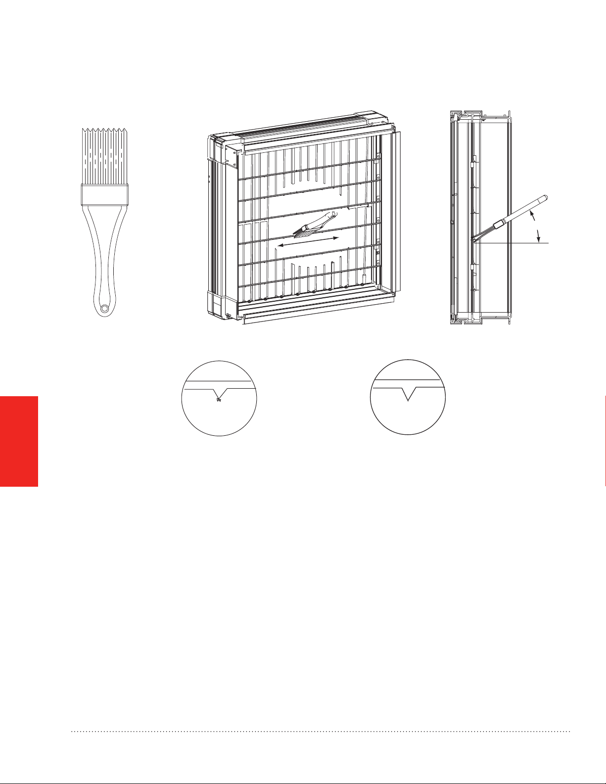
Mantenimiento
MÓDULO DE MEJORAMIENTO
30°
FUNCIONAMIENTO
Y SERVICIO
¡LOS PUNTOS SON FILOSOS! TENGA MUCHO CUIDADO DURANTE LA LIMPIEZA
PUNTO DE IONIZACIÓN CON RESIDUOS PUNTO DE IONIZACIÓN DESPUÉS DE LA LIMPIEZA
MS28916A
Fig. 19. Eliminación de acumulaciones en los puntos de ionización.
8. Vuelva a instalar la pantalla de seguridad.
9. Deslice el módulo de mejoramiento nuevamente dentro del gabinete.
10. Modelos FH8000A: vuelva a conectar el cable de alimentación y el cable del sensor de ujo (ver Fig. 11 en
la página 15).
Modelos FH8000F: vuelva a conectar el cable de alimentación (ver Fig. 15 en la página 17).
11. Vuelva a colocar la puerta del limpiador de aire mejorado Honeywell.
12. Coloque el interruptor del limpiador de aire mejorado Honeywell en la posición “ON” (encendido).
13. Encienda el sistema de calefacción y refrigeración.
22
Limpiador de aire mejorado TrueCLEAN™ 68-0308EFS—03
Page 89

Localización y solución de problemas
ADVERTENCIA: riesgo de electrocución.
Si no tiene en cuenta esta advertencia, existe el riesgo de lesiones personales o de muerte.
Los siguientes procedimientos dejarán componentes eléctricos al descubierto. Antes de realizar la eparación,
siempre desconecte la energía eléctrica principal del sistema. Es posible que exista más de un interruptor de
desconexión.
PRECAUCIÓN: riesgo de lesiones personales.
Si no tiene en cuenta esta advertencia, existe el riesgo de lesiones personales.
Las siguientes instrucciones son únicamente para ser utilizadas por personal calicado.
El limpiador de aire mejorado Honeywell tiene una luz del indicador de encendido ubicada en la puerta ver Fig.
17 en la página 19). Esta luz del indicador de encendido se ilumina cuando se instala la puerta del limpiador de
aire mejorado Honeywell, cuando el interruptor de encendido está en la posición “ON” (encendido) Y cuando
el soplador del controlador de aire o el soplador del equipo de calefacción están en funcionamiento, y (para los
modelos FH8000A) cuando se detecta ujo de aire. Si la luz del indicador de encendido no se ilumina, siga los
siguientes pasos para localizar y solucionar el problema.
1. Verique que la puerta del limpiador de aire mejorado Honeywell esté instalada.
NOTA: existe un imán en la puerta (ver Fig. 16 en la página 19) que se utiliza para activar un interruptor de
eguridad del suministro eléctrico cuando se instala la puerta. El suministro eléctrico no energizará el
limpiador de aire, a menos que el interruptor de seguridad esté activado.
2. Verique que el interruptor de encendido del limpiador de aire mejorado Honeywell se encuentre en la osición
“ON” (encendido).
3. Compruebe que el soplador del sistema de calefacción y refrigeración esté funcionando.
4. Conrme que haya suministro de energía eléctrica.
Modelos FH8000A: de 208 a 230 V CA.
Modelos FH8000F: 120 V CA.
5. Modelos FH8000A ÚNICAMENTE: compruebe que el cable del sensor de ujo esté conectado al suministro
eléctrico (ver Fig. 11 en la página 15).
NOTA: aunque el limpiador de aire mejorado Honeywell reciba energía eléctrica, no se encenderá, a menos ue
el sensor de ujo de aire detecte ujo de aire o que el enchufe de derivación del sensor de ujo de aire
esté insertado.
a. Si aún no funciona, desconecte el cable del sensor de ujo de aire y el cable de alimentación del
uministro eléctrico.
b. Quite el módulo de mejoramiento del gabinete del limpiador de aire mejorado Honeywell y revise l
interruptor de ujo de aire (ver Fig. 14 en la página 16).
c. Compruebe que el interruptor de ujo de aire esté asentado correctamente en su soporte y que l cable
del interruptor de ujo de aire esté conectado en la parte posterior del interruptor. Vuelva a colocar el
modulo de mejoramiento.
FUNCIONAMIENTO
Y SERVICIO
Limpiador de aire mejorado TrueCLEAN™ 68-0308EFS—03
23
Page 90

Localización y solución de problemas
d. Vuelva a conectar el cable de alimentación al suministro eléctrico e inserte momentáneamente el
puente (de la bolsa de piezas) para deshabilitar el sensor de ujo de aire.
e. Si la luz del indicador de encendido se ilumina, entonces reemplace el sensor de ujo de aire.
6. Modelos FH8000F ÚNICAMENTE: conrme que la energía eléctrica provista desde los terminales del
EAC del control del equipo de calefacción está siendo transmitida a través del cableado hacia el suministro
eléctrico del limpiador de aire mejorado Honeywell.
7. Instale la puerta en el limpiador de aire mejorado Honeywell.
8. Coloque el interruptor de encendido en la posición “ON” (encendido).
9. Si se han completado todos los pasos anteriores y la luz del indicador de encendido sigue sin luminarse,
reemplace el módulo de mejoramiento. Tenga en cuenta que, aparte de la pantalla de seguridad, no hay otra
pieza que pueda repararse en el módulo de mejoramiento.
FUNCIONAMIENTO
Y SERVICIO
24
Limpiador de aire mejorado TrueCLEAN™ 68-0308EFS—03
Page 91

Especicaciones, dimensiones y aprobaciones
Especicaciones
Tabla 1. Especicaciones.
Especicación
Color Gris imperial oscuro
Material del gabinete Acero calibre 20 con pintura en polvo
Electricidad 208 a 230 VCA a 60 Hz, 0.5A máx 120 VCA, a 60 Hz, 0.5A máx
Rango de temperatura
de funcionamiento
Rango de humedad de
funcionamiento
Máximo ujo de aire
(CFM)
Eciencia Equivalente a MERV 15
Filtro de reemplazo FR8000A1620 FR8000A2020 FR8000A2520 FR8000F1625 FR8000F2025
Caída de presión inicial
(in de c.a.) a un ujo de
aire de 492 pies/min
FH8000A 1620 FH8000A 2020 FH8000A 2520 FH8000F 1625 FH8000F 2025
De -20 a 70 °C (-4 a 158 °F)
Del 5% al 95% de HR (sin condensación)
1350 1800 2000 1600 2000
0.22 in de c.a. 0.25 in de c.a. 0.22 in de c.a. 0.25 in de c.a. 0.25 in de c.a.
Dimensiones
Dimensiones: FH8000A 1620 FH8000A 2020 FH8000A 2520 FH8000F 1625 FH8000F 2025
1
Tabla 2. Dimensiones en pulgadas y (mm).
A 18 5/8 (473) 22 1/8 (562) 25 5/8 (651) 18 3/8 (467) 21 7/8 (556)
B 15 3/8 (391) 18 7/8 (479) 22 3/8 (568) 15 1/8 (384) 18 5/8 (473)
C 13 1/8 (333) 13 1/8 (333) 13 1/8 (333) 11 1/8 (283) 11 1/8 (283)
D 17 5/8 (448) 21 1/8 (537) 24 5/8 (626) 17 1/2 (445) 21 (533)
E 19 7/8 (505) 19 7/8 (505) 19 7/8 (505) 22 1/8 (562) 22 1/8 (562)
F 22 1/4 (565) 22 1/4 (565) 22 1/4 (565) 25 1/4 (641) 25 1/4 (641)
G 11 1/4 (286) 11 1/4 (286) 11 1/4 (286) N/D N/D
Normas y aprobaciones
El limpiador de aire está probado y certicado conforme a lo siguiente:
• CSA 22.2 Nº 187-09
• UL 900 (sólo el ltro)
NOTA: el limpiador de aire mejorado Honeywell está certicado por la CSA sólo en cuanto a riesgos de
descargas y de incendios eléctricos.
APÉNDICES
1 Consulte la Fig. 21 en la página 27 para ver los dibujos con dimensiones.
Limpiador de aire mejorado TrueCLEAN™ 68-0308EFS—03
25
Page 92

Especicaciones, dimensiones y aprobaciones
CURVAS DE CAÍDA DE PRESIÓN
.35
CAÍDA DE
PRESIÓN
DEL FILTRO
EN H20
.30
.25
.20
.15
.10
.05
16 x 20 in.
(406 x 508 mm)
16 x 25 in.
(406 x 635 mm)
20 x 20 in.
(508 x 508 mm)
20 x 25 in.
(508 x 635 mm)
25 x 20 in.
(635 x 508 mm)
APÉNDICES
0
200 400 600 800 1000 1200 1400 1600 1800 2000
CAUDAL DE FLUJO (CFM)
Fig. 20. Curvas de caída de presión
MS32379
26
Limpiador de aire mejorado TrueCLEAN™ 68-0308EFS—03
Page 93

Especicaciones, dimensiones y aprobacionesEspecicaciones, dimensiones y aprobaciones
FH8000A
G
1 3/16 (30.2)
A
DB
PARTE SUPERIOR E INFERIOR TÍPICA DE 3/8 IN (9.5 MM)
C
1 1/2 (38.1)
FH8000F
E
F
1 3/16" (30.2)
1 3/16 (30.2)
1 3/16 (30.2)
A
PARTE SUPERIOR E INFERIOR TÍPICA DE 7/16 IN (11.1 MM)
C
1 15/16˝ (49.2)
Fig. 21. Dimensiones en pulgadas (mm).1
1 Consulte la Tabla 2 en la página 25 para ver las dimensiones designadas por letras.
Limpiador de aire mejorado TrueCLEAN™ 68-0308EFS—03
D
B
APÉNDICES
E
F
1 3/16˝ (30.2)
1 3/16˝ (30.2)
MS28917A
27
Page 94

Lista de piezas de TrueCLEAN™
FH8000F1625 FH8000F2025 FH8000A1620 FH8000A2020 FH8000A2520
A Puerta 50053268-006 50053268-007 50053268-008 50053268-009 50053268-010
B Filtro FR8000F1625 FH8000F2025 FH8000A1620 FH8000A2020 FH8000A2520
C Módulo de mejoramiento 50053268-001 50053268-002 50053268-003 50053268-004 50053268-005
D Pantalla de seguridad 50053268-011 50053268-012 50053268-013 50053268-014 50053268-015
E Sensor de ujo de aire NA 50053268-018
F Cable de alimentación y
accesorios (componentes
de instalación)
50053268-016 50053268-017
APÉNDICES
1
A
E
Puerta FH8000A.
1
A
Puerta FH8000F
2
A
Filtro
Módulo de mejoramiento
Pantalla de seguridad
Sensor de flujo de aire (FH8000A)
E
1
F
Cable de alimentación y accesorios (componentes de instalación FH8000A)
2
F
Cable de alimentación y accesorios (componentes de instalación FH8000F)
2
A
1
F
2
F
M32380
28
Limpiador de aire mejorado TrueCLEAN™ 68-0308EFS—03
Page 95

Garantía limitada de 5 años
Honeywell garantiza que este producto no tiene defectos en la mano de obra ni en los materiales en condiciones
de uso y servicio normales durante un período de cinco (5) años desde la fecha de compra del consumidor. Si en
cualquier momento, durante el período de vigencia de la garantía, se determina que el producto está defectuoso
o no funciona adecuadamente, Honeywell lo reparará o lo reemplazará (a elección de Honeywell).
Si el producto presenta defectos,
(i) llévelo al lugar donde lo compró, junto con la factura de compra u otra prueba de compra que incluya la fecha
en la que compró el producto; o
(ii) comuníquese con el Servicio al cliente de Honeywell al 1-800-468-1502. El Servicio al cliente determinará si el
producto debe enviarse a la siguiente dirección: Honeywell Return Goods, Dock 4 MN10-3860, 1985 Douglas Dr.
N., Golden Valley, MN 55422, o si se le puede enviar un producto de reemplazo.
Esta garantía no cubre los gastos de remoción ni de reinstalación. Esta garantía no se aplicará si Honeywell
demuestra que el defecto o funcionamiento inadecuado fueron causados por daños que se produjeron mientras
el producto estaba en posesión de un consumidor.
La única responsabilidad de Honeywell será la de reparar o reemplazar el producto dentro de los términos
mencionados anteriormente. HONEYWELL NO SERÁ RESPONSABLE DE LA PÉRDIDA NI DAÑO DE NINGÚN
TIPO, QUE INCLUYE CUALQUIER DAÑO INCIDENTAL O CONSECUENTE QUE RESULTE, DIRECTA
O INDIRECTAMENTE, DE CUALQUIER INCUMPLIMIENTO DE CUALQUIER GARANTÍA, EXPRESA O
IMPLÍCITA, O DE CUALQUIER OTRA FALLA DE ESTE PRODUCTO. Algunos estados no permiten la exclusión
o limitación de los daños incidentales o consecuentes por lo que esta limitación podría no aplicarse en su caso.
ESTA GARANTÍA ES LA ÚNICA GARANTÍA EXPRESA QUE HONEYWELL REALIZA SOBRE ESTE
PRODUCTO. LA DURACIÓN DE CUALQUIERA DE LAS GARANTÍAS IMPLÍCITAS, INCLUYENDO LAS
GARANTÍAS DE COMERCIABILIDAD O DE APTITUD PARA UN FIN DETERMINADO, ESTÁN LIMITADAS A
LOS CINCO AÑOS DE DURACIÓN DE ESTA GARANTÍA. Algunos estados no permiten limitaciones en relación
a la duración de una garantía implícita, de manera tal que la limitación anterior puede no aplicarse en su caso.
Esta garantía le otorga derechos legales especícos pero es posible que usted goce de otros derechos que
varían de un estado a otro.
Si tiene preguntas sobre esta garantía, escriba a Honeywell Customer Relations, 1985 Douglas Dr, Golden Valley,
MN 55422 o llame al 1 (800) 468-1502. En Canadá, escriba a Retail Products ON15-02H, Honeywell Limited/
Honeywell Limitée, 35 Dynamic Drive, Toronto, Ontario M1V4Z9.
Limpiador de aire mejorado TrueCLEAN™ 68-0308EFS—03
APÉNDICES
29
Page 96

Automatización y control desenlace
Honeywell International Inc.
1985 Douglas Drive North
Golden Valley, MN 55422
Honeywell Limited–Honeywell Limitée
35 Dynamic Drive
Toronto, Ontario M1V 4Z9
http://yourhome.honeywell.com
® Marca Registrada en los EE. UU.
© 2011 Honeywell International Inc.
68-0308EFS—03 M.S. Rev. 01-11
Impreso en EE. UU.
 Loading...