


™
Dolphin
®
with Windows
CE 6.0
6510 Mobile Computer
User’s Guide

Disclaimer
Honeywell International Inc. (“HII”) reserves the right to make changes in specifications and other infor-
mation contained in this document without prior notice, and the reader should in all cases consult HII to
determine whether any such changes have been made. The information in this publication does not represent a commitment on the part of HII.
HII shall not be liable for technical or editorial errors or omissions contained herein; nor for incidental or
consequential damages resulting from the furnishing, performance, or use of this material.
This document contains proprietary information that is protected by copyright. All rights are reserved.
No part of this document may be photocopied, reproduced, or translated into another language without
the prior written consent of HII.
Web Address: www.honeywellaidc.com
Trademarks
Dolphin is a trademark or registered trademarks of Hand Held Products, Inc. or Honeywell International
Inc.
Microsoft, Windows, Windows Mobile, Windows Embedded Handheld, Windows CE, Windows NT,
Windows 2000, Windows ME, Windows XP, ActiveSync, Outlook, and the Windows logo are trademarks
or registered trademarks of Microsoft Corporation.
Other product names mentioned in this manual may be trademarks or registered trademarks of their
respective companies and are the property of their respective owners.
Other Trademarks
The Bluetooth trademarks are owned by Bluetooth SIG, Inc., U.S.A. and licensed to Honeywell
International Inc.
Patents
For patent information, please refer to www.honeywellaidc.com/patents.
© 2013 Honeywell International Inc. All rights reserved.

Table of Contents
Chapter 1 - Agency Approvals
Label Locations ................................................................................................................. 1-1
N4313-TTL Safety & RF Approvals by Country: ................................................................. 1-1
R&TTE Compliance Statement – 802.11a/b/g/n/ and or Bluetooth……………………. ....... 1-2
Dolphin RF Terminal—802.11a/b/g/n and/or Bluetooth ...................................................... 1-2
Chapter 2 - Getting Started
Out of the Box ................................................................................................................... 2-1
Initial Setup for Dolphin 6510 Terminals ............................................................................. 2-1
LED Indicators ............................................................................................................. 2-2
Home Screen .................................................................................................................... 2-4
Title Bar ............................................................................................................................. 2-4
Horizontal Scroll ................................................................................................................ 2-5
Horizontal Scroll ................................................................................................................ 2-6
Tile Bar .............................................................................................................................. 2-6
Pop-Up Menus .................................................................................................................. 2-6
Selecting Programs ........................................................................................................... 2-6
File Explorer ...................................................................................................................... 2-7
File Provisioning on the Dolphin 6510 ................................................................................ 2-8
Search ............................................................................................................................... 2-8
Turning Power On/Off ........................................................................................................ 2-9
Suspend Mode ............................................................................................................ 2-9
Resetting the Terminal ....................................................................................................... 2-9
Chapter 3 - Hardware Overview
Standard Terminal Configurations...................................................................................... 3-1
Dolphin Peripherals/Accessories for the Dolphin 6510 ....................................................... 3-1
USB Communication Cable for the Dolphin 6510 ............................................................... 3-2
Front Panel Features ......................................................................................................... 3-2
Using the Touch Panel ...................................................................................................... 3-3
Installing a Screen Protector ........................................................................................ 3-4
Back Panel Features ................................................................................................ ......... 3-4
Left Side Panel Features ................................................................................................... 3-5
Right Side Panel Features ................................................................................................. 3-6
Top Panel Features ........................................................................................................... 3-6
Bottom Panel Features ...................................................................................................... 3-7
Battery Power .................................................................................................................... 3-7
Battery Pack ................................................................................................................ 3-8
Managing Battery Power .............................................................................................. 3-9
Storage Guidelines ...................................................................................................... 3-9
Hardware Maintenance .................................................................................................... 3-10
Installing Memory Cards ............................................................................................ 3-10
Dolphin 6510 Technical Specifications ............................................................................. 3-12
iii

Chapter 4 - Using the Keypad
Overview ............................................................................................................................4-1
Navigation Keys .................................................................................................................4-1
Basic Keys .........................................................................................................................4-1
Alpha/Numeric Modes ........................................................................................................4-2
Alpha Indicators on the Number Keys ...........................................................................4-2
Function Key Combinations ................................................................................................4-2
CTRL Key Combinations ....................................................................................................4-3
Program Buttons ................................................................................................................4-3
Chapter 5 - Using the Image Engine
Overview ............................................................................................................................5-1
Available Image Engines ....................................................................................................5-1
Depth of Field ...............................................................................................................5-1
Supported Bar Code Symbologies .....................................................................................5-2
Activating the Engine .........................................................................................................5-3
Capturing Images (56XX Engine only) ................................................................................5-3
Chapter 6 - Using the Laser Engine
Overview ............................................................................................................................6-1
Available Laser Engines ................................................................ .....................................6-1
Depth of Field - N4313-TTL ................................ ..........................................................6-1
Supported Bar Code Symbologies .....................................................................................6-1
Activating the Engine .........................................................................................................6-2
Decoding a Bar Code .........................................................................................................6-2
Chapter 7 - System Settings
Overview ............................................................................................................................7-1
Clock & Alarms ..................................................................................................................7-2
Personal Menu ...................................................................................................................7-3
Buttons. ........................................................................................................................7-3
Program Buttons ..........................................................................................................7-5
System Menu .....................................................................................................................7-8
About ...........................................................................................................................7-9
Backlight ................................ ...................................................................................... 7-9
Certificates ................................................................................................................. 7-10
Encryption .................................................................................................................. 7-11
HSM SystemInfo ........................................................................................................ 7-11
Error Reporting ................................ ................................................................ ........... 7-12
Managed Programs .................................................................................................... 7-12
Memory ...................................................................................................................... 7-12
Power. ........................................................................................................................ 7-14
Regional Settings. ...................................................................................................... 7-16
Remove Programs ..................................................................................................... 7-16
Screen ............................................................................................................................. 7-18
SIP Configuration ................................................................................................ .............7-19
iv

Task Manager .................................................................................................................. 7-20
Chapter 8 - Communication
Connecting the Dolphin 6510-USB Communication Cable ..................................................8-1
Charging Terminal with USB Cable ....................................................................................8-1
Connections Menu ............................................................................................................ 8-3
Receiving Data ...................................................................................................................8-3
Connections Manager ........................................................................................................8-4
To Access the Connections Manager ...........................................................................8-4
Tasks ...........................................................................................................................8-5
Advanced .....................................................................................................................8-6
Dolphin Wireless Manager .................................................................................................8-7
Dolphin Wireless Manager Window ..............................................................................8-7
Enabling the Radios. ....................................................................................................8-8
Accessing Radio Configuration Utilities ................................................................ .........8-8
Network Cards ...................................................................................................................8-9
Connecting and Synchronizing the Terminal and Workstation ............................................8-9
Installing Additional Software ........................................................................................... 8-12
Adding Programs Using ActiveSync or Windows Mobile Device Center ...................... 8-12
Connecting the Terminal to a Wireless Network ......................................................... 8-13
Adding Programs Using the Internet ................................................................ ........... 8-13
Software Upgrades .......................................................................................................... 8-14
Chapter 9 - Working with the Bluetooth Radio
Enabling the Bluetooth Radio .............................................................................................9-1
Pairing and Trusted Devices ..............................................................................................9-2
Connecting to Other Bluetooth Devices ..............................................................................9-2
Transferring Files ...............................................................................................................9-4
Making the Terminal Discoverable .....................................................................................9-6
Chapter 10 - Dolphin HomeBase (Model 6500-HB)/eBase
(Model 6500-EHB) Device
Overview ..........................................................................................................................10-1
Front Panel ......................................................................................................................10-2
Back Panel ....................................................................................................................... 10-3
Powering the Dolphin HomeBase Device ......................................................................... 10-4
eBase Clamp-on Ferrite Core Installation ......................................................................... 10-4
Charging the Battery ........................................................................................................ 10-5
Charging a Spare Battery ........................................................................................... 10-6
Checking Battery Power ................................................................................................... 10-6
Technical Specifications ................................................................................................... 10-7
Chapter 11 - Dolphin 6500 Net Base Device (Model 6500-NB)
Overview ..........................................................................................................................11-1
v

Parts and Functions ......................................................................................................... 11-2
Front Panel ................................................................................................................ 11-2
Back Panel ................................ ................................................................ ................. 11-3
Bottom Panel .............................................................................................................. 11-4
Power ..............................................................................................................................11-4
Connecting Power to the Net Base ............................................................................. 11-4
Charging the Battery ........................................................................................................ 11-5
To Power a Terminal and Charge its Battery .............................................................. 11-5
Communication ................................................................................................................11-5
Software Requirements .............................................................................................. 11-5
Connecting the Dolphin Terminal to the Net Base ............................................................ 11-5
Mounting the Net Base ..................................................................................................... 11-6
Chapter 12 - Dolphin QuadCharger Device
Overview ..........................................................................................................................12-1
QuadCharger Device ....................................................................................................... 12-1
Battery Charging ..............................................................................................................12-2
Recommendations for Storing Batteries ........................................................................... 12-3
Troubleshooting ...............................................................................................................12-3
Technical Specifications ................................................................................................... 12-4
Chapter 13 - Customer Support
Technical Assistance ....................................................................................................... 13-1
Product Service and Repair .............................................................................................. 13-1
Limited Warranty ..............................................................................................................13-1
Limited Warranty Duration ................................................................................................ 13-2
How to Extend Your Warranty .................................................................................... 13-2
vi
(CISPR 22)
Compliance
Light
1
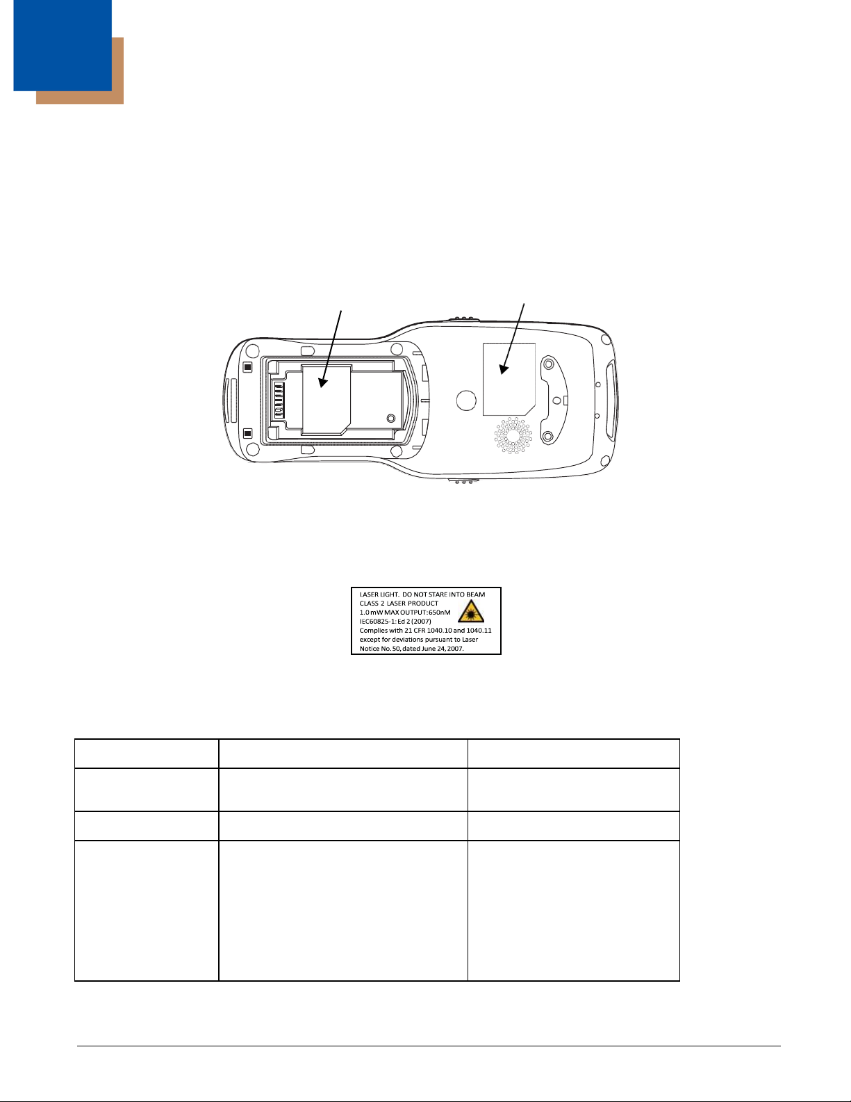
Agency Approvals
Label Locations
Dolphin 6510 mobile computers meet or exceed the requirements of all applicable standards
organizations for safe operation. However, as with any electrical equipment, the best way to ensure safe
operation is to operate them according to the agency guidelines that follow. Read these guidelines
carefully before using your mobile computer.
Label
Laser
Label
Laser Safety Label
If the following label is attached to your product, it indicates that the product contains an engine with a
laser aimer:
N4313-TTL Safety & RF Approvals by Country:
Country Safety RF (Radio)
U.S.A.
Canada*
European IEC 60825-1:2007 EN55022
Community
UL60950-1
C-UL CSA C22.2 No. 60950-1-07 ICES-003, RSS 247
IEC62471:2008
EN609501:2006+A11:2009+A1:2010+A12:2011 EN300 440-2
FCC Part 15, Sub part B, Sub
part C, Sub part E
EN55024:2010
EN300 328
EN301 489-1
EN301 489-17
EN301 893
EN62311
EN62209-2
Class B
* Does not apply to N4313-TTL laser engine.
1 - 1

R&TTE Compliance Statement—802.11a/b/g/n and/or Bluetooth
Dolphin RF terminals are in conformity with all essential requirements of the R&TTE Directive (1999/5/
EC).
This product is marked with
2200
in the R&TTE Directive, 1999/5/EC. The equipment is intended for use throughout the European
Community; PAN European Frequency Range: 2.402–2.480 GHz.
Restrictions for use in France are as follows:
• Indoor use: Maximum power (EIRP*) of 100 mW for the entire 2.400–2.4835 GHz
• Outdoor use: Maximum power (EIRP*) of 100 mW for the 2.400–2.454 GHz band & maximum power
(EIRP*) of 10 mW for the 2.454–2.483 GHz band.
Frequency band 5180-5320 MHz is restricted to indoor use only.
The CE Mark on the product indicates that the system has been tested to and conforms with the
provisions noted within the 2004/108/EC Electromagnetic Compatibility Directive and the 2006/95/
EC Low Voltage Directive. Honeywell shall not be liable for use of our product with equipment (i.e.,
power supplies, personal computers, etc.) that is not CE marked and does not comply with the Low
Voltage Directive.
For further information, contact:
Hand Held Products Europe B.V.
Nijverheidsweg 9-13
5627 BT Eindhoven
The Netherlands
!
in accordance with the Class II product requirements specified
Warning! To prevent possible hearing damage, do not listen at high volume levels for long periods.
CB Scheme
Certified to CB Scheme IEC 60950-1.
FCC RF Radiation Exposure Statement
This equipment complies with FCC RF radiation exposure limits set forth for an uncontrolled environment.
Dolphin RF Terminal—802.11a/b/g/n and/or Bluetooth
This device complies with Part 15 of the FCC Rules. Operation is subject to the following two conditions:
(1) this device may not cause harmful interference, and (2) this device must accept any interference
received, including interference that may cause undesired operation.
This equipment has been tested and found to comply with the limits for a Class B digital device pursuant
to Part 15 of the FCC Rules. These limits are designed to provide reasonable protection against harmful
interference in a residential installation. This equipment generates, uses, and can radiate radio frequency
energy and, if not installed and used in accordance with the instructions, may cause harmful interference
to radio communications. However, there is no guarantee that interference will not occur in a particular
installation. If this equipment does cause harmful interference to radio or television reception, which can
be determined by turning the equipment off and on, the user is encouraged to try to correct the
interference by one or more of the following measures:
• Reorient or relocate the receiving antenna.
• Increase the separation between the equipment and receiver.
1 - 2

• Connect the equipment into an outlet on a circuit different from that to which the receiver is connected.
• Consult the dealer or an experienced radio/TV technician for help.
If necessary, the user should consult the dealer or an experienced radio/television technician for
additional suggestions. The user may find the following booklet helpful: “Something About Interference.”
This is available at FCC local regional offices. Our company is not responsible for any radio or television
interference caused by unauthorized modifications of this equipment or the substitution or attachment of
connecting cables and equipment other than those specified by our company. The correction is the
responsibility of the user. Use only shielded data cables with this system.
In accordance with FCC 15.21, changes or modifications not expressly approved by the party responsible
for compliance could void the user’s authority to operate the equipment.
This device and its antenna must not be co-located or operating in conjunction with any other
antenna or transmitter. To maintain compliance with FCC RF exposure guidelines for bodyworn operation, do not use accessories that contain metallic components.
CAUTION! This equipment may generate or use radio frequency energy. Changes or modifications
to this equipment may cause harmful interference unless the modifications are expressly approved in
the instruction manual. The user could lose the authority to operate this equipment if an unauthorized
change or modification is made.
Canadian Compliance
This radio transmitter has been approved by Industry Canada to operate with the antenna types listed
below with
the maximum permissible gain and required antenna impedance for each antenna type indicated.
Antenna types not included in this list,
having a gain greater than the maximum gain indicated for that type, are strictly prohibited for use with
this device.
Under Industry Canada regulations, this radio transmitter may only operate using an antenna of a type
and maximum
(or lesser) gain approved for the transmitter by Industry Canada. To reduce potential radio interference to
other users, the antenna type and its gain should be so chosen that the equivalent isotropically radiated
power (e.i.r.p) is not more than that necessary for successful communication.
This device complies with Industry Canada license-exempt RSS standard(s).
Operation is subject to the following two conditions:
(1)this device may not cause interference,
and (2) this device must accept any interference, including interference that may cause undesired
operation of the device.
Le présent émetteur radio a été approuvé par Industrie Canada pour fonctionner avec les types
d'antenne énumérés ci-dessous et ayant un gain admissible maximal et l'impédance requise pour chaque
type d'antenne. Les types d'antenne non inclus dans cette liste, ou dont le gain est supérieur au gain
maximal indiqué, sont strictement interdits pour l'exploitation de l'émetteur.
Conformément à la réglementation d'Industrie Canada, le présent émetteur radio peut fonctionner avec
une antenne d'un type et d'un gain maximal (ou inférieur)
approuvé pour l'émetteur par Industrie Canada. Dans le but de réduire les risques de brouillage
radioélectrique à l'intention des autres utilisateurs, il faut choisir le type d'antenne et son gain de sorte
que la puissance isotrope rayonnée équivalente (p.i.r.e.) ne dépasse pas l'intensité nécessaire à
l'établissement d'une communication satisfaisante.
Le présent appareil est conforme aux CNR d'Industrie Canada applicables aux appareils radio exempts
de licence.
L'exploitation est autorisée aux deux conditions suivantes :
(1)l'appareil ne doit pas produire de brouillage, et (2) l'utilisateur de l'appareil doit accepter tout brouillage
radioélectrique subi, même si le brouillage est susceptible d'en compromettre le fonctionnement.
1 - 3

IC RF Exposure Statement
NII frequency band 5150-5250 MHz is restricted to indoor use only.
For European Community Users
Honeywell Scanning & Mobility Product Environmental Information
Refer to www.honeywellaidc.com/environmental for the RoHS / REACH / WEEE
information.
1 - 3
2
Getting Started
Out of the Box
Verify that your carton contains the following items:
• Dolphin 6510 mobile computer (the terminal)
• Battery pack (3.7v, Li-Ion)
• AC power supply (KSAS0120500200D5; Input: 100-240V AC, 50/60Hz 0.4 Amps; Output: 5 Volts DC, 2.0 A)
• Localized plug adapters
Note: Be sure to keep the original packaging in case you need to return the Dolphin terminal for service; see
Customer Support on page 12-1.
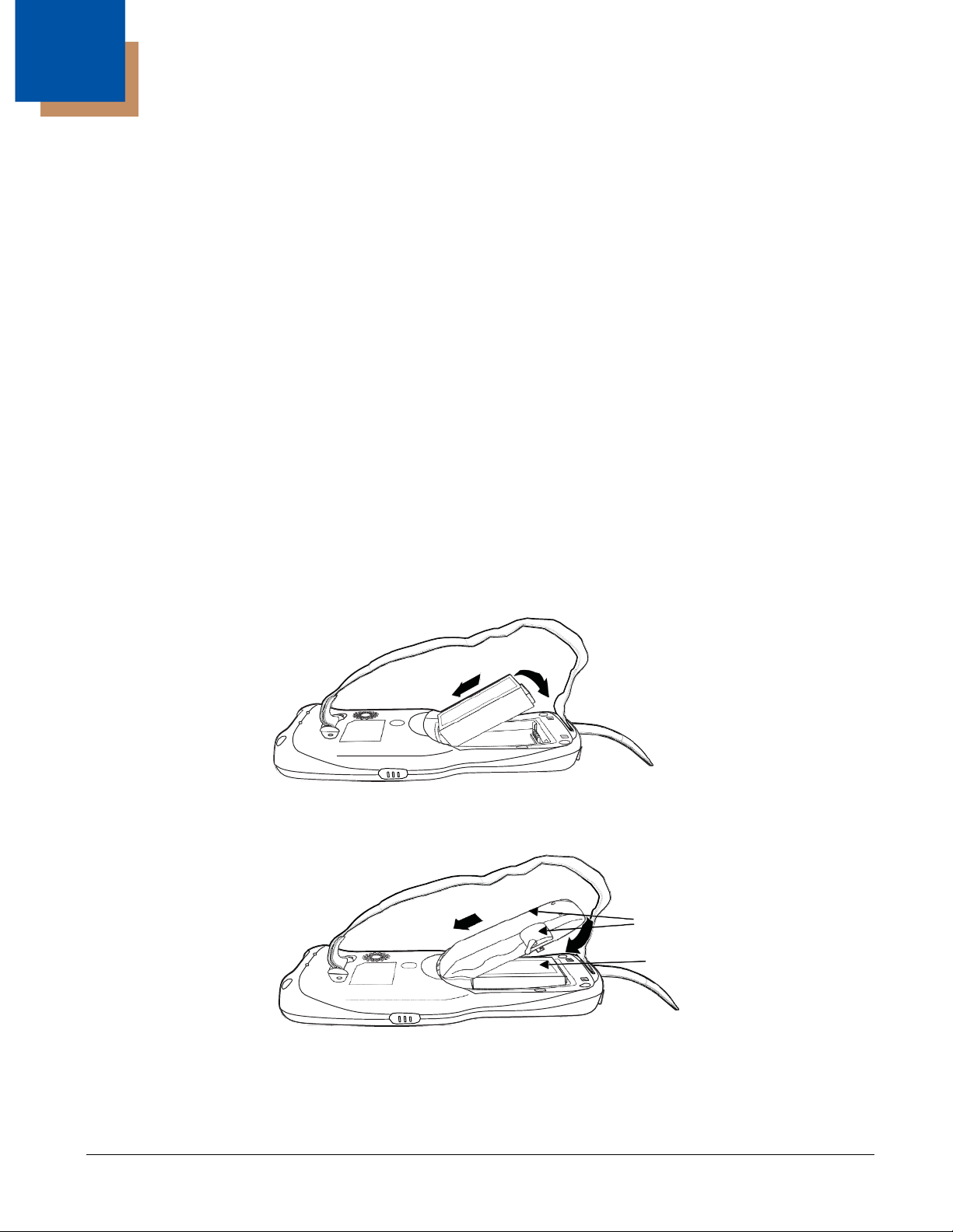
Initial Setup for Dolphin 6510 Terminals
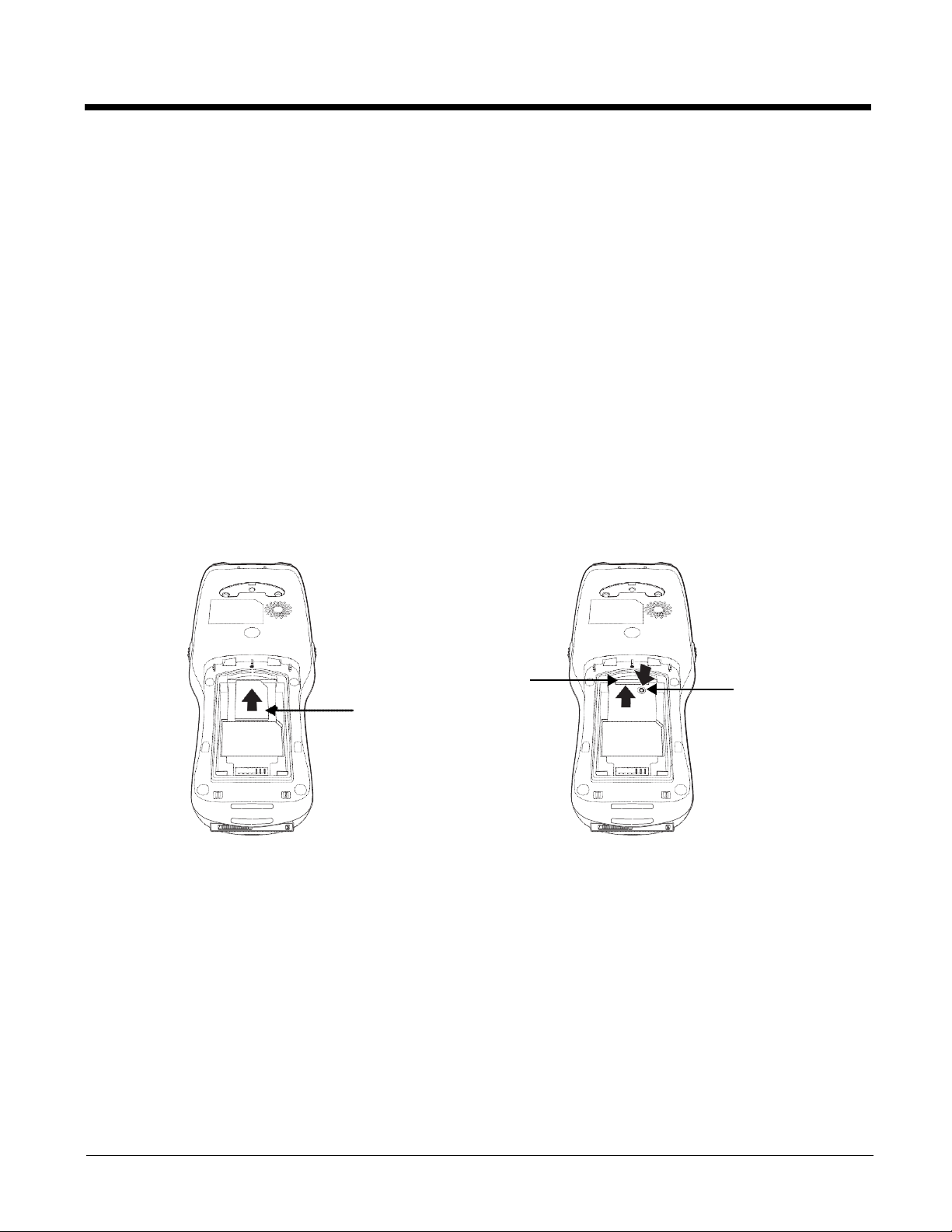
Step 1. Install the Battery
The Dolphin 6510 is shipped with the battery packaged separate from the unit. Follow the steps below to
install the battery.
1. Release the strap making it convenient to reach the cover.
2. Remove the battery compartment cover by turning the cover locks upward and removing the cover.
3. Insert the battery into the battery well with the labels facing upward.
4. Replace the cover with a hinging motion and turn the locks downwards.
Note: The battery door must be installed prior to booting the unit.
5. Replace the hand strap.
2 - 1
2
We recommend use of Honeywell Li-Ion battery packs. Use of any non-Honeywell battery may result in damage not
covered by the warranty.
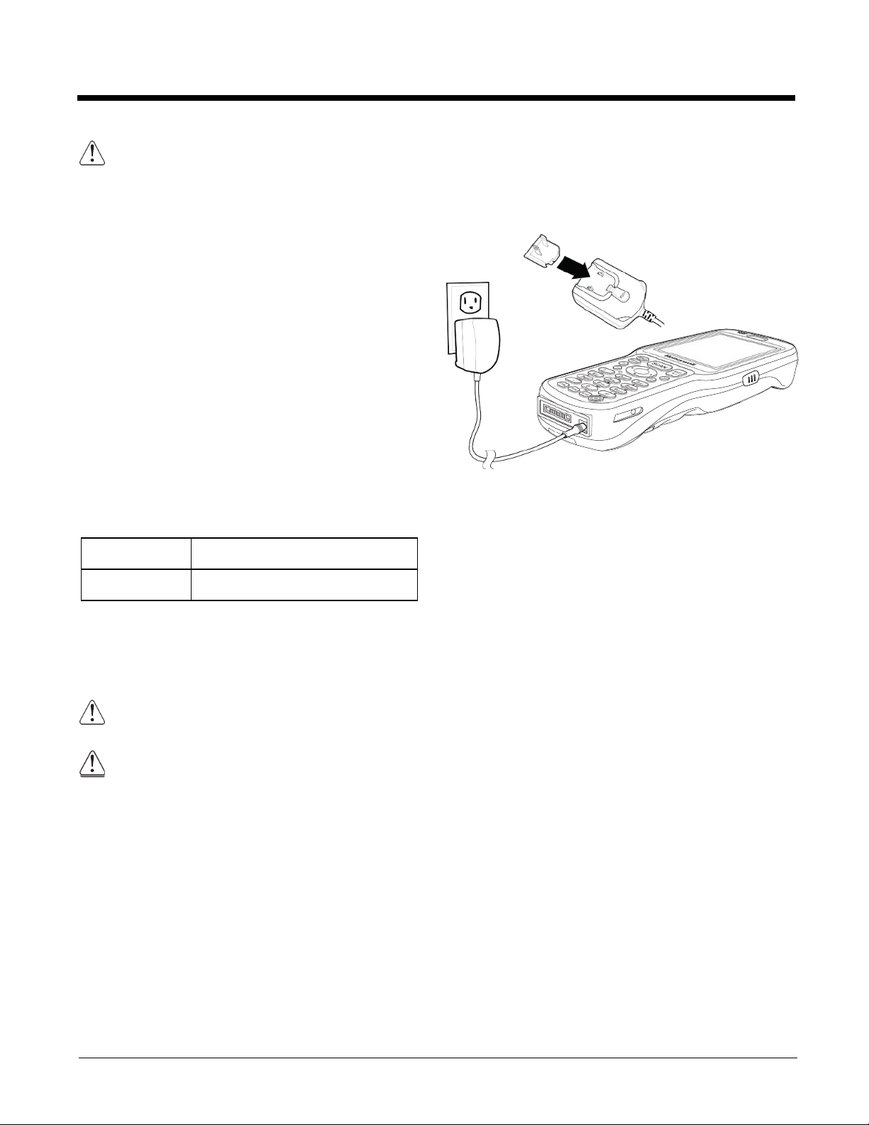
Step 2. Charge the Batteries
Dolphin 6510s ship with the battery pack
significantly discharged of power. Charge the
battery pack with the Dolphin charging cable until
the LED turns green (red while charging). The
average charge time for a fully depleted battery is
7 1/2 hours. It takes less time if the battery has
some charge.
1. Attach the appropriate plug adapter to the
plug of the power cable.*
2. Insert the plug into the appropriate power
source.
3. Plug the Dolphin power cable into the DC
Power Jack (see page 3-7) on the bottom end
of the unit.
Important:
all non-persistent memory.
Removing the battery from the terminal erases
LED Indicators
Red LED On
Charging
1
3
Green LED On
Battery is fully charged
*This power cable can also be used to power the
Dolphin 6510 while in the Dolphin HomeBase
(Model 6500-HB)/eBase (Model 6500-EHB)
Device (see page 10-1).
We recommend use of Honeywell peripherals, power cables, and power adapters compiled with
L.P.S. Use of any non-Honeywell peripherals, cables, or power adapters may cause damage not
covered by the warranty.
Ensure all components are dry prior to mating terminals/batteries with peripheral devices. Mating
!
wet components may cause damage not covered by the warranty.
2 - 2
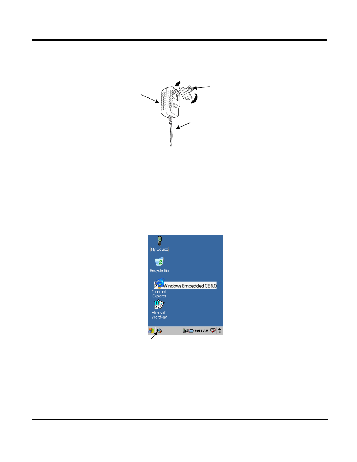
The power adapter on the power cable converts the voltage from the power source to 5 volts DC. Only
power adapter cables from Honeywell convert the voltage appropriately. The power cable contains a plug
adapter for each geography (US, UK, EU, etc.).
Power Adapter
Plug Adapter
Power Cable
Step 3. Boot the Terminal
The terminal begins booting as soon as power is applied and runs by itself. Do NOT press any keys or
interrupt the boot process.
When the boot process is complete, the Desktop appears, and the terminal is ready for use.
Desktop
Note: You can access the Desktop any time by tapping the Change Views icon in the command bar and selecting
Desktop on the popup menu.
Tap to change views
2 - 3
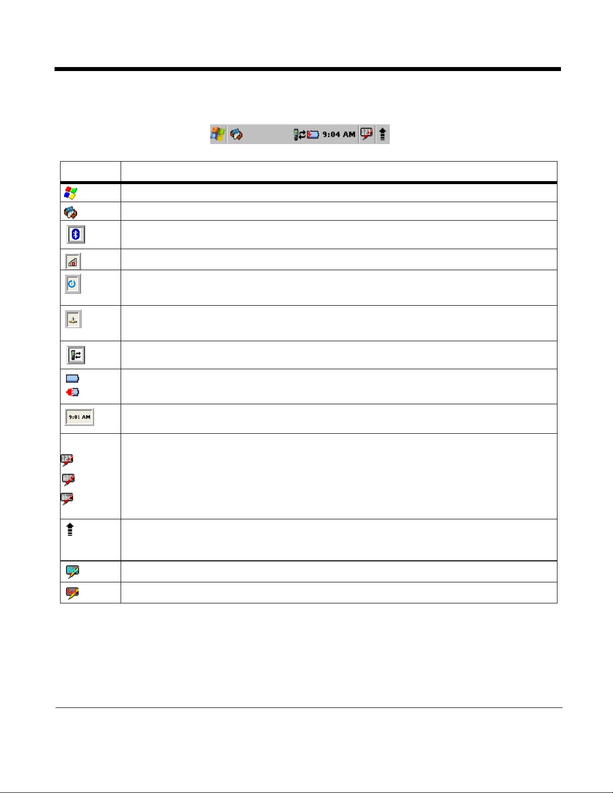
Icon
Meaning
Opens the Start menu.
Tap to change views between open applications or to return to the desktop.
Accesses the Bluetooth radio. Double tap this icon to open the Bluetooth Handler (see page 8-1).
Shows signal strength of WiFi radio. (A red X indicates it is not currently associated to an AP.)
Double tap to configure your WLAN Secure Wireless Client. For complete configuration
instructions, download the Honeywell Secure Wireless (SWC) Client User’s Guide from
www.honeywellaidc.com.
Indicates Ethernet communications. When the terminal is undocked, no icon appears. When it is
docked without a cable, the icon has a red X through it. When docked with a cable connected, this
icon displays.
Indicates that the USB communication cable is connected. Double tap to display USB status
window.
Indicates the status of battery power. Double tap to open the Power control panel setting.
When this icon shows a red power plug, it indicates the device is using external power.
Displays the current time. Double tap to change the time and date.
28-key keypad - Indicates whether the keypad is standard alpha (uppercase and lowercase), all
caps alpha, or in numeric mode. Press the ALPHA button on the keypad to switch modes.
52-key keypad - Press the SFT key twice in rapid succession to toggle between upper and
lowercase as indicated by the icon. Pressing the SFT key once temporarily toggles for the next
typed key and then reverts back. You can also change from upper/lowercase by selecting the
“ABC”/”abc” indicator and selecting CAP on the keyboard that displays. Pressing a number key
results in a number appearing in the application. Pressing SFT key once and typing a number on
the keypad results in a special character appearing in the application.
The up arrow allows you to turn the Wireless LAN and Bluetooth connection on or off. It also
allows you to toggle between the Keyboard and Transcriber. When Keyboard is selected, a
keyboard is displayed so you can tap text and number keys. Transcriber recognizes handwriting
and symbols entered using the stylus.
Indicates Blue mode.
Indicates Red mode.
Command Bar Icons
The command bar, located at the bottom of application screens, provides access to many system
functions and programs.
2 - 4
Using the Stylus
The terminal comes with a stylus included in a loop on the hand strap. Use this stylus (or your finger) to
select or enter information on the touch screen. The stylus functions as a mouse; generally, a tap is the
same as a click.
Tap
Drag
Tap & hold Tap and hold the stylus on an item and a pop-up menu appears. On the pop-up menu, tap
Tap the touch screen once or double tap to open menu items and select options.
Hold the stylus on the screen and drag across the screen to select text and images.
the action of the task you want to perform.
Use of objects, such as paper clips, pencils, or ink pens on the touch screen can damage the input
panel and may cause damage not covered by the warranty.
For more information about the touch screen, see Touch Screen Display on page 3-2.
Selecting Programs
Tap Start > Programs. To open a program, tap the icon on the menu.
Pop-Up Menus
You can quickly choose an action for an item using the pop-up menus.
1. Tap and hold the stylus on the item name. The pop-up menu appears.
2. Lift the stylus and tap the action you want to perform.
The contents of pop-up menus change according to the program you are using.
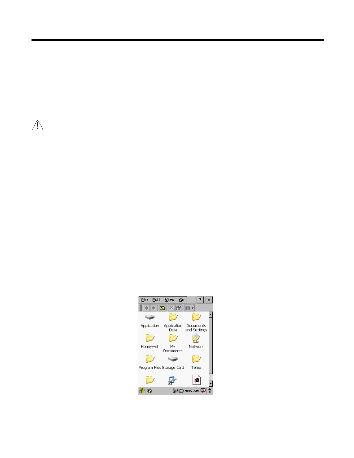
Using Windows Explorer
Use Windows Explorer to navigate through the files on your system. On the desktop, double tap the My
Device icon and Windows Explorer opens to the root level.
Move files by tapping and holding on the file, then tapping Cut, Copy or Paste on the pop-up menus that
appear.
2 - 5

Dolphin 6510 WPAN and WPAN/WLAN
• Microsoft Windows CE 6.0
•
•
• 28-key numeric keypad (alpha shifted) and 52-
•
•
•
•
•
•
Dolphin 6510)
3
Hardware Overview
Dolphin 6510 terminals include a number of standard terminal configurations as well as charging and
communication peripherals and accessories to maximize the efficiency of your application setting.
Standard Terminal Configurations
There are two standard Dolphin 6510 configurations: WPAN only and WPAN/WLAN. Both configurations
include the following options; however, the WPAN/WLAN configuration has both a Bluetooth radio and an
802.11a/b/g/n radio.
TI Cortex-A8 1GHz
512MB RAM X 1 GB (non-volatile) Memory
key full alpha and numeric keypad
3.5” transflective active matrix 65k color LCD
display with backlight, QVGA (240 x 320)
Li-Ion battery: 3.7V / 3300mAh / 12.2 Wh
N560x image engine with laser aiming or
N4313 laser engine
(WPAN) - Bluetooth radio
(WPAN/WLAN) - Bluetooth and
802.11a/b/g/n radio
Dolphin power cable (included with each
2 –6
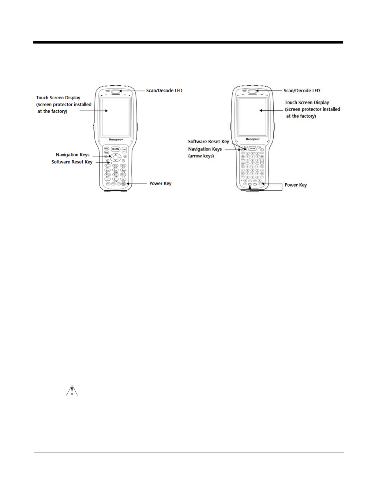
Front Panel Features
(28-key keypad (numeric)
(52-key keypad (full alphanumeric)
Scan/Decode LED
The LED lights red when you press the Scan trigger in scanning applications.
The LED lights green when a scanned bar code is successfully decoded.
The LED lights red while the main battery is charging.
The LED lights green when the main battery charging is completed.
The LED lights blue or red during soft and hard resets.
Keypad
The LED is user-programmable.
28-key numeric keypad (alpha shifted) and 52-key full alphanumeric keypads are available.
Microphone
The integrated microphone can be used for audio recording.
Touch Screen Display
The display is a 3.5” transflective active matrix, 65k color LCD display with a backlight, QVGA
(240 x 320 resolution); see Display Backlight on page 3-3. The touch panel is a 4-wire analog
resistive touch.
Dolphin 6510s ship with a screen protector already installed over the touch screen lens
to help prevent damage to the touch screen. Do NOT remove this screen protector before
initial use. Honeywell recommends using screen protectors, especially for applications
that require high volume interfacing with the touch screen. For more information, see
Using Screen Protectors on page 3-3. You can purchase additional screen protectors by
contacting your Honeywell sales representative.
2 - 7
For touch screen input, use the stylus included with the terminal or your finger. The method
you choose depends on which one is most appropriate for your application. While there is a
great deal of variation in different applications, you generally achieve greater accuracy with the
stylus for buttons or icons that are close together.
Use of objects, such as paper clips, pencils, or ink pens on the touch screen can damage
the input panel and may cause damage not covered by the warranty.
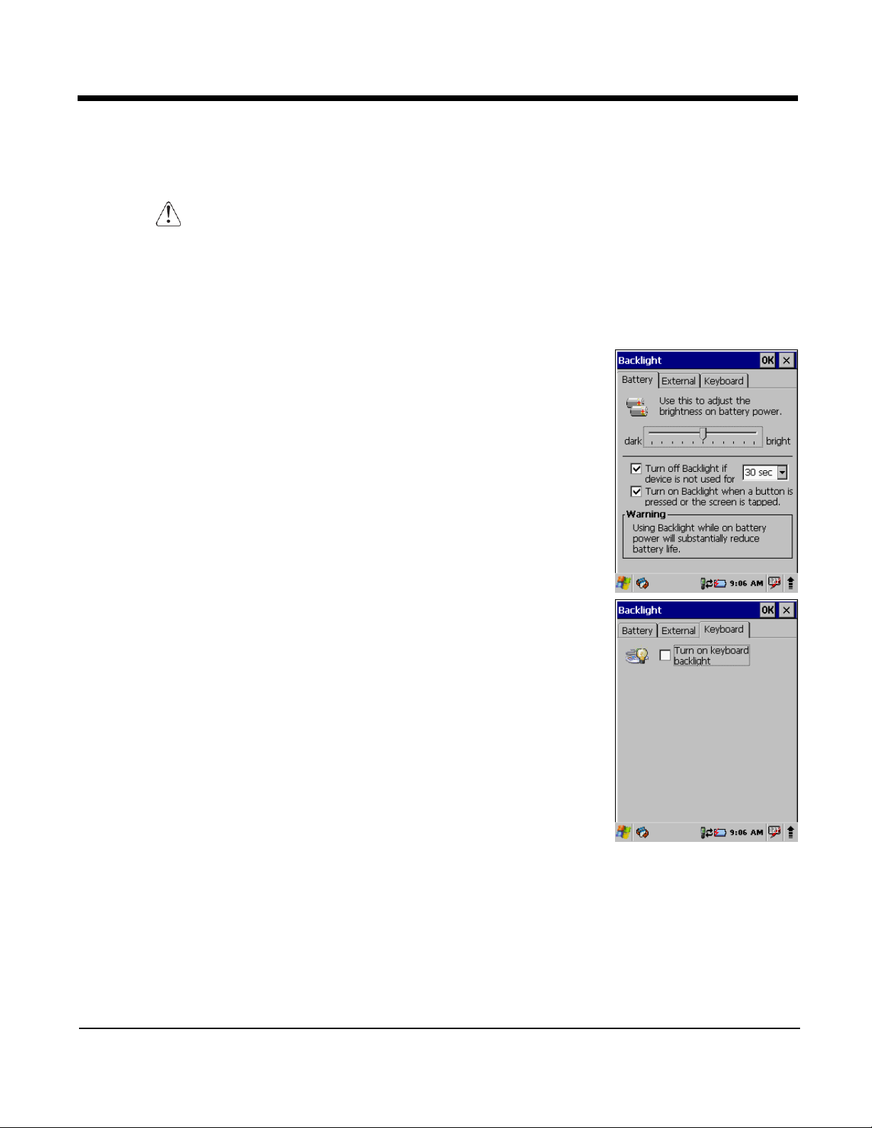
Display Backlight
The intensity of the backlight of the touch screen display may be changed, and the backlight may be
programmed to turn off after the terminal has been idle for a specified period of time.
To adjust the intensity of the backlight while on battery power, tap Start > Settings > Control Panel >
double tap Backlight.
Screen Backlight - Battery/External Power
Move the slider to adjust the screen backlight while on battery power.
You may turn the screen backlight off if the device is not used for a
designated period of time by checking the option and designating the
desired time period.
You may also turn on the screen backlight when a button is pressed or the
screen is tapped by selecting the appropriate checkbox.
Note: Using the backlight option while on battery power substantially reduces
battery life.
You may make the same changes when on external power by tapping the
External tab.
Keyboard Backlight
To turn on the keypad backlight, check the checkbox.
The duration of backlight of keypad synchronizes with LCD backlight’s.
Using Screen Protectors
Honeywell defines proper use of the terminal touch panel display as using a
screen protector and proper stylus. Screen protectors maintain the ongoing
integrity (i.e., prevent scratching) of the touch panel, which is why their use is
recommended for applications that require a high to medium level of interface
with the touch panel.
Honeywell continues to advocate the use of screen protectors on all Dolphin terminals. We recommend
implementing a screen protector replacement program to ensure that screen protectors are replaced
periodically when signs of damage/wear are noticeable. For general use, we recommend replacing the
screen protector every thirty (30) days. However, replacement cycles vary according to the average level
of touch panel use in your application.
2 - 8
Replacement screen protectors can be purchased directly from Honeywell. Contact a Honeywell sales
representative for details.
Honeywell also mandates use of a proper stylus, which is one that has a stylus tip radius of no less than
0.8mm. Use of the Honeywell stylus included with the terminal is recommended at all times.
Honeywell’s warranty policy covers wear on the touch panel for the first 12 months provided that a screen
protector is applied and an approved stylus is used for the 12-month duration covered by the warranty.
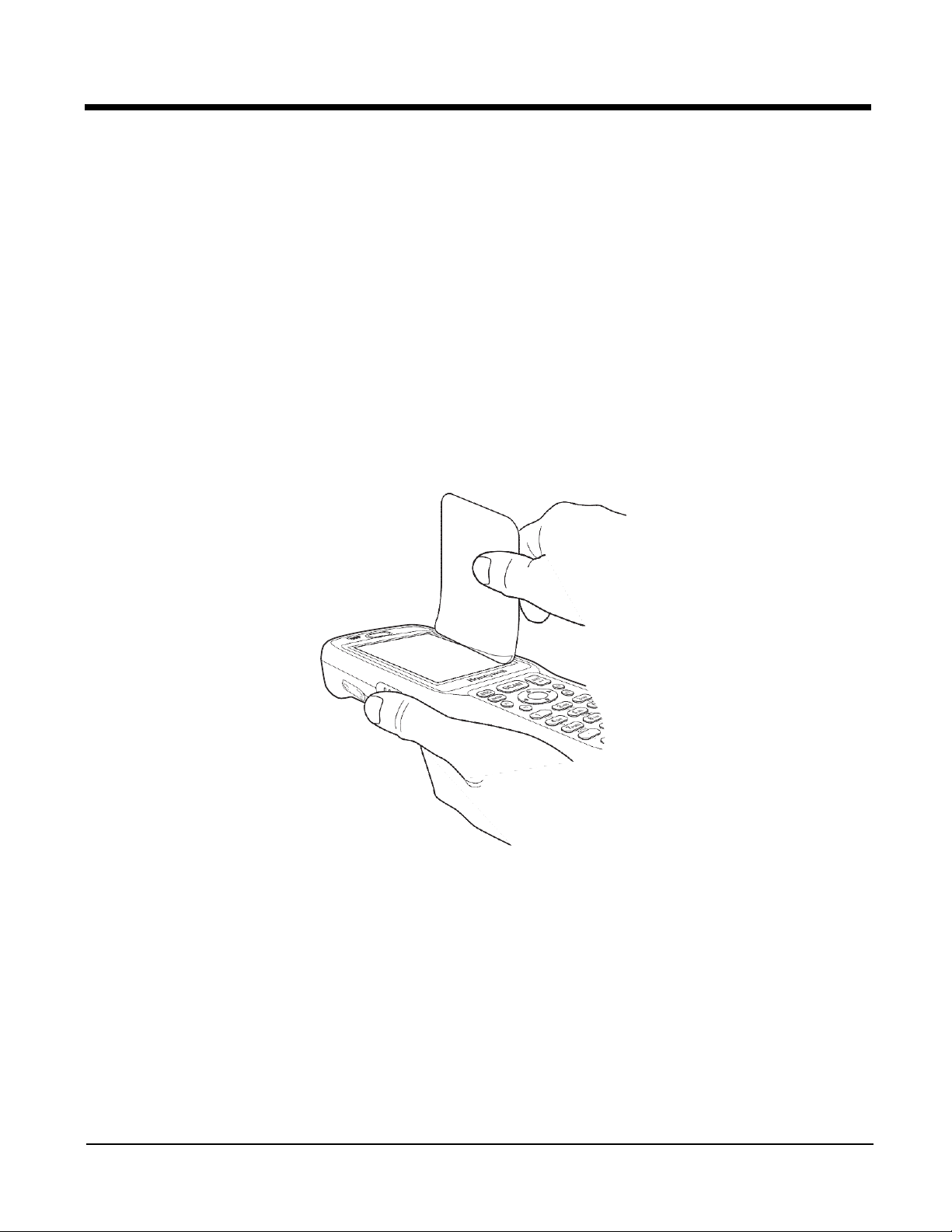
Removing the Screen Protector
Dolphin 6510s ship with a touch screen protector already installed. To replace the screen protector, you
must remove the one already installed.
1. Press the red Power button to suspend the 28-key unit or press the Blue then Z (Power) keys to
suspend the 52-key unit.
2. Using a strong, flat, plastic card (e.g., credit card) wedge the edge of the card under the existing
screen protector. Catch the edge of the screen protector and pull it up and away from the touch
panel.
Note: If you have one, you can also use the small plastic squeegees designed for touch panels.
3. Wipe the screen with a clean, non-abrasive, lint-free cloth.
Note: Use ionized air, if available, to blow additional dirt or particles off the touch panel.
Installing Your Screen Protector
When installing a new screen protector, use a flat plastic card (e.g., credit card) to apply the screen
protector smoothly and remove any air bubbles.
Note: If you have one, you can also use the small plastic squeegees designed for touch panels.
1. Press the red Power button to put the terminal in Suspend Mode on the 28-key Dolphin 6510 or
press the Blue then Z (Power) keys on the 52-key Dolphin 6510.
3 - 4
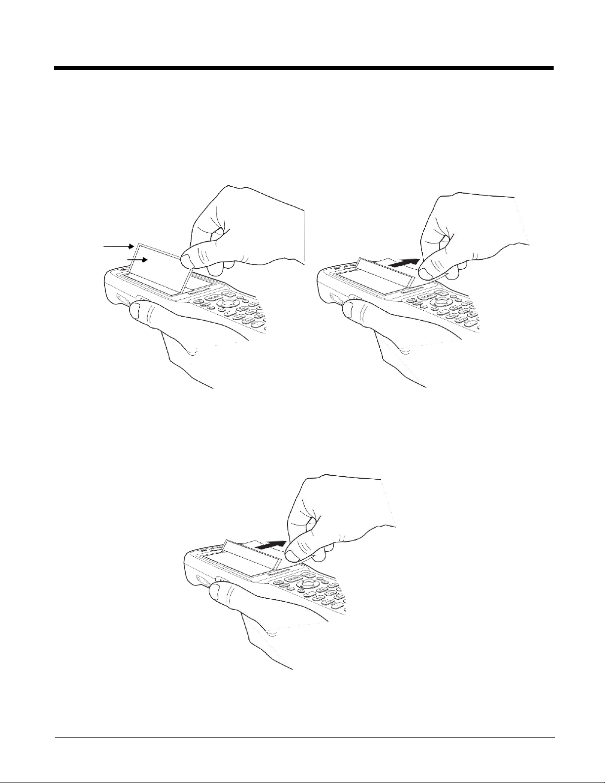
2. Clean the touch panel thoroughly with a clean, non-abrasive, lint-free cloth. Make sure nothing is on
the touch panel.
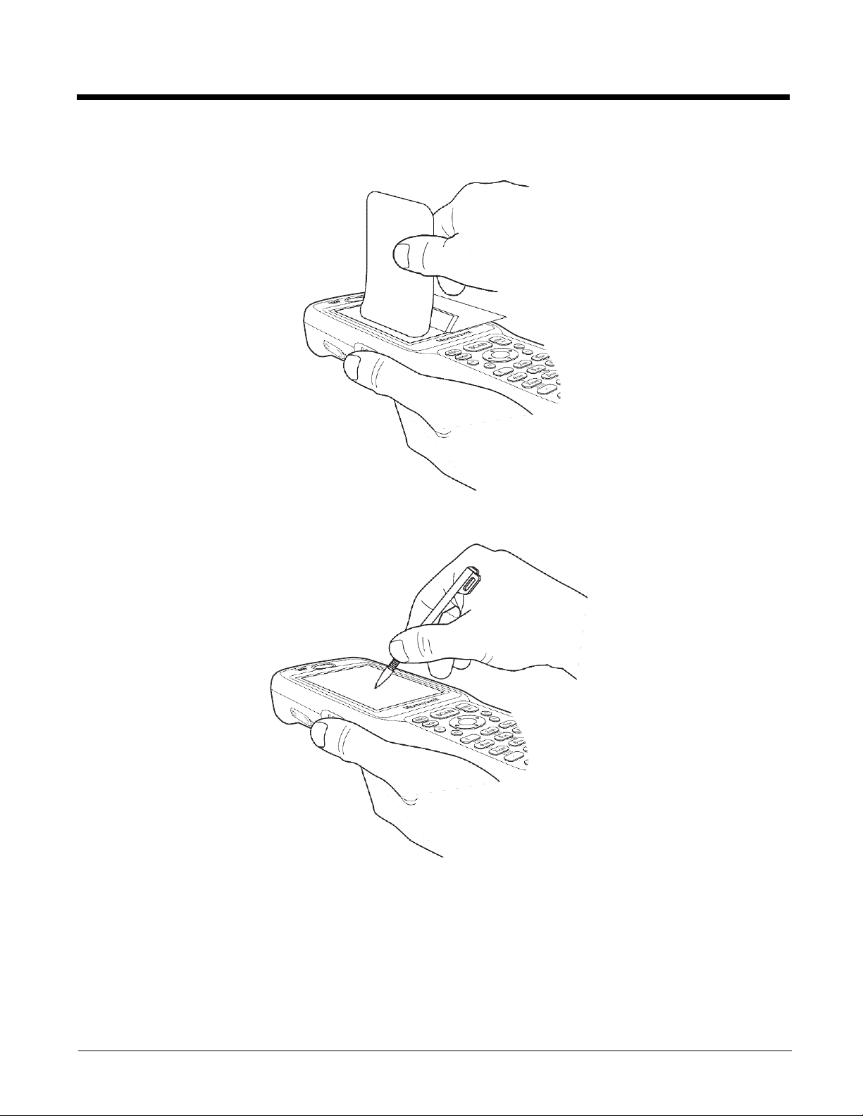
3. Release the left edge of the backing paper on the screen protector.
4. Align the exposed edge of the screen protector along the left edge of the touch panel.
Make sure that it lies flush with edges of the touch panel.
Backing
Paper
Screen Protector
Note: To reposition the screen protector, lift up gently and reapply.
5. Use the card on top of the screen protector to smooth it out as you pull on the backing paper.
3 - 5
6. Pull smoothly and evenly from left to right until the screen protector is applied. Press gently but
firmly. Use the card as necessary to smooth out any air pockets or bumps after application.
7. Press the Power key to wake the terminal and check the touch panel with the stylus.
8. Verify that the screen accepts input from the stylus as usual. If not, re-apply the screen protector.
9. Press the red Power button to put the terminal back in Suspend Mode on the 28-key Dolphin 6510
or press the Blue then Z (Power) keys on the 52-key Dolphin 6510.
10. Clean the surface of the screen protector with a clean, non-abrasive, lint-free cloth.
11. Press the Power key to wake the terminal again.
3 - 6
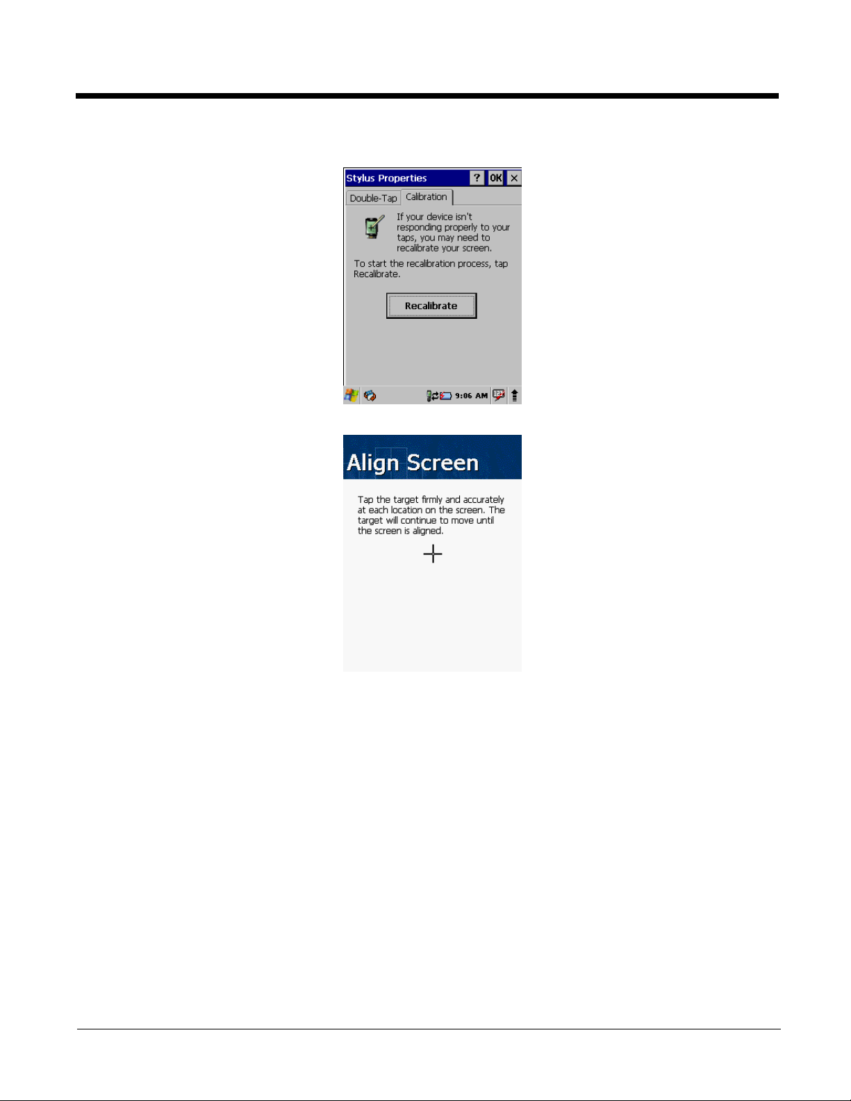
12. For maximum performance, recalibrate the screen. Tap Start > Settings > Control Panel > double
tap Stylus > Calibration tab.
13. Tap Recalibrate and follow the instructions on the screen.
3 - 7
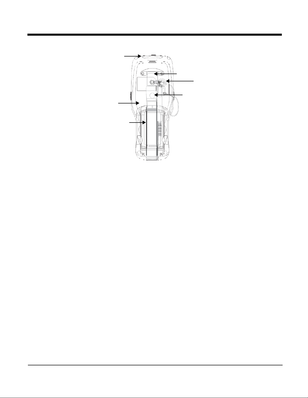
Back Panel Features
Image Engine Window
Hand Strap
Finger
Saddle
Installed Battery
Hand Strap (with Stylus)
Speaker
Rear Scan Button
The Dolphin 6510 comes with an adjustable, elastic hand strap. The strap is attached to the
device with the two small screws. It is threaded through the slot on the bottom of the back of
the unit.
Keep in mind that the hand strap covers the battery. When you want to replace the battery, you
will need to adjust the hand strap accordingly.
Rear Scan Button
The Dolphin 6510 has a Scan button conveniently located on the back of the unit. This button
works like the SCAN button located on the front of the unit. Pressing this button can also
resume a suspended device.
Finger Saddle
This is a slightly depressed and angled area of the back housing that is designed to cradle or
“saddle” your finger while holding the terminal. This unique ergonomic design makes the
terminal comfortable to hold and helps prevent you from accidentally dropping the terminal.
Installed Battery
For information about installing the battery, see Changing the Main Battery Pack on page 3-13
Speaker
For information about battery power, see Battery Power on page 3-12.
The integrated speaker sounds audio signals as you scan bar code labels and enter data, but
emits no ambient noise on system activity (i.e., processor, memory access, radio traffic, etc.).
The speaker can also be used for playing sounds (e.g., WAV or MP3 files).
3 - 8
The speaker meets the following SPL levels at 40cm:
• 500Hz–67db
•
1KHz–72db
Stylus
•
4KHz–72db
Dolphin 6510 terminals ship with a stylus inserted in a loop on the hand strap. Store the stylus
in the hand strap when you’re not using it; see Using the Stylus on page 2-5.
Installing Memory Cards
The Dolphin 6510 supports Secure Digital (SD) memory cards from 512MB up to 8GB in capacity. The
recommended SD cards are 2GB and 4GB ATP®-brand, which have been tested for reliability. You can
purchase these SD cards by contacting your Honeywell sales representative.
To install an SD card:
1. Remove the battery door on the back of the unit.
2. Remove the battery.
3. Insert the SD card with the label facing upward by pressing down the small pin and sliding the SD
card into the SD card connector until you feel it lock into position. The notch on the SD card should
be in the upper-right hand corner.
Note: If your unit has trouble reading the SD card, the SD card may not have been inserted correctly. If depressing
the small pin allows the card to eject, the card was not properly inserted and “locked in.”
SD Card
SD Card
4. Replace the battery and battery door.
5. Tap the Power or SCAN key to resume operation.
6. To verify that the operating system recognizes the new memory card, open Windows Explorer and
navigate to My Device\Storage Card.
Pin
To remove an SD card:
1. Remove the battery door on the back of the unit.
2. Remove the battery.
3. Press the SD card towards the front of the terminal until you hear a click to confirm that it has
unlocked. The card will stops when it hits the pin.
4. Depress the small pin at the edge of the card. The card will pop out enough for you to grab its edge.
3 - 9
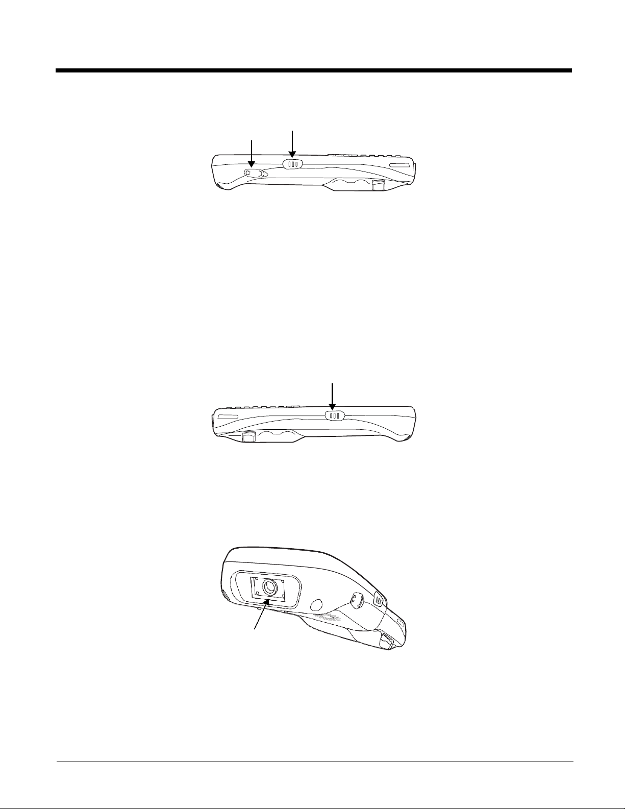
Left Side Panel Features
Side Button
There is a button like this on both side panels. You can use the Programs Buttons option in
the Control Panel to change the functionality of the side buttons.
Headset Jack
The rubber door on the right side panel provides access to the headset jack. This is a 2.5mm
audio jack that supports a headset with a mono speaker and microphone.
When closed, the side door seals the terminal from moisture and particle intrusion thus
preserving the terminal’s environmental rating.
Right Side Panel Features
Headset Jack
Side Button
Side Button
Side Button
There is a button like this on both side panels. You can use the Programs Buttons option in the
Control Panel to change the functionality of the side buttons.
Top Panel Features
Imager or Laser Aperture Window
Imager or Laser Aperture Window
The angled image engine reads and decodes most popular bar code symbologies and takes
images like a digital camera (imager engine only). For more information, see Using the Image
Engine on page 5-1 or see Using the Laser Engine on page 6-1.
3 - 10
DC Power Jack
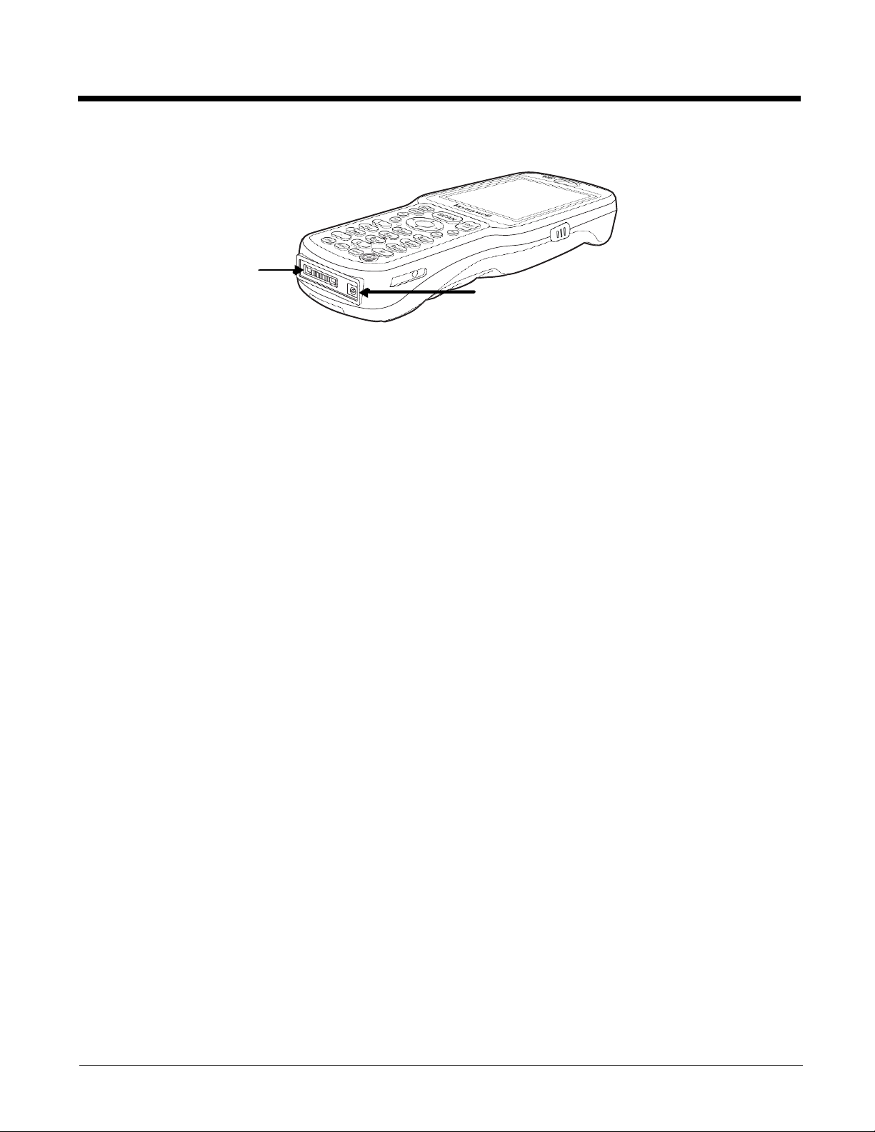
Bottom Panel Features
I/O Connector
DC Power Jack
The DC power jack receives external power from the Dolphin power cable that is included in
the box with the terminal. When connected to the Dolphin power cable, the terminal is powered
and the main battery pack is charging.
I/O Connector
The I/O mechanical connector is designed to work exclusively with Dolphin 6510 peripherals
and cables. This connector powers the terminal, charges the main battery, and facilitates
communication. This connector supports full speed USB 1.1 communication (up to 12 Mbps)
and RS-232 communications with a maximum speed of 115Kbps and seven baud rate
settings.
Through this connector, you can communicate with a host workstation via Microsoft
ActiveSync; see ActiveSync Communication on page 7-3
The I/O connector supports the following signals:
•
DC IN
•
Transmitted Data
•
Request To Send
•
USB Host +5V
•
USB Host D+
•
USB Host D-
•
USB Host Detect
•
Clear To Send
•
Received Data
•
GND
•
RS-232 Shutdown
•
USB Client D+
•
USB Client D-
•
USB Client +5V
Note:
Signals referenced are for a DTE device.
Dolphin Peripherals/Accessories for the Dolphin 6510
The following items are sold separately and enhance your Dolphin 6510’s capabilities.
3 - 11
 Loading...