


N56XX Decoded Engine
For 5610/5613, 5680/5683, 5690/5693 Engines
User’s Guide

Disclaimer
Honeywell International Inc. (“HII”) reserves the right to make changes in specifications and other information contained in this
document without prior notice, and the reader should in all cases consult HII to determine whether any such changes have been
made. The information in this publication does not represent a commitment on the part of HII.
HII shall not be liable for technical or editorial errors or omissions contained herein; nor for incidental or consequential damages
resulting from the furnishing, performance, or use of this material.
This document contains proprietary information that is protected by copyright. All rights are reserved. No part of this document
may be photocopied, reproduced, or translated into another language without the prior written consent of HII.
2010-2013 Honeywell International Inc. All rights reserved.
Web Address:
Microsoft® Windows®, Windows NT®, Windows 2000, Windows ME, Windows XP, and the Windows logo are trademarks or
registered trademarks of Microsoft Corporation.
The Bluetooth® word mark and logos are owned by Bluetooth SIG, Inc.
Other product names or marks mentioned in this document may be trademarks or registered trademarks of other companies
and are the property of their respective owners.
www.honeywellaidc.com

Product Agency Compliance
Note: It is the OEM manufacturer’s responsibility to comply with applicable regulation(s) in regard to standards for specific
equipment combinations.
USA and Canada
UL Statement (Recognized component)
UL listed: UL60950-1, 2nd Edition.
C-UL listed: CSA C22.2 No.60950-1-07, 2nd Edition for I.T.E. product safety.
Europe
Honeywell shall not be liable for use of our product with equipment (i.e., power supplies, personal computers, etc.) that is
not CE marked and does not comply with the Low Voltage Directive.
For CE-related inquiries, contact:
Hand Held Products Europe B.V.
Nijverheidsweg 9-13
5627 BT Eindhoven
The Netherlands
D-Mark Statement
Certified to EN 60950-1 Information Technology Equipment product safety.
International
LED Safety Statement
LEDs have been tested and classified as “EXEMPT RISK GROUP” to the standard: IEC 62471:2006.
CB Scheme
Certified to CB Scheme IEC 60950-1, Second Edition.
Laser Safety Statement
Note: Applies only to N56X3 models.
This device has been tested in accordance with and complies with IEC60825-1 ed2 (2007)
The Standard also states that the following be included in all user documentation, spec sheets, and brochures, which
describe this product:
"Caution - Use of controls or adjustments or performance of procedures other than those specified herein may
result in hazardous radiation exposure."
Note: This warning states that altering the inner parts of the laser engine in a way not specified in the user guide may cause
light levels to exceed Class 2 limits. It is not an issue when using under normal conditions.

Required Safety Labels
ESD Precautions
The engine is shipped in ESD safe packaging. Use care when handling the scan engine outside its packaging. Be sure grounding wrist straps and properly grounded work areas are used.
Dust and Dirt
The engine must be sufficiently enclosed to prevent dust particles from gathering on the engine and lens. When stocking the
unit, keep it in its protective packaging. Dust and other external contaminants will eventually degrade unit performance.
Honeywell Scanning & Mobility Product Environmental Information
Refer to www.honeywellaidc.com/environmental for the RoHS / REACH / WEEE information.
Patents
For patent information, please refer to www.honeywellaidc.com/patents.

Table of Contents
Chapter 1 - Getting Started
Introduction ..........................................................................................................................1-1
About This Manual...............................................................................................................1-1
Unpacking Your Device .......................................................................................................1-1
OEM Engine Models ............................................................................................................1-1
Connecting the Development Engine to the PC ..................................................................1-2
Connecting with USB .....................................................................................................1-2
Connecting with RS232 Serial Port................................................................................1-3
Menu Bar Code Security Settings........................................................................................1-4
Setting Custom Defaults ......................................................................................................1-4
Resetting the Custom Defaults ............................................................................................1-5
Chapter 2 - Programming the Interface
Introduction ..........................................................................................................................2-1
Programming the Interface - Plug and Play.........................................................................2-1
Keyboard Wedge ...........................................................................................................2-1
Laptop Direct Connect ...................................................................................................2-1
RS232 Serial Port ..........................................................................................................2-1
USB IBM SurePos..........................................................................................................2-2
USB PC or Macintosh Keyboard....................................................................................2-2
USB HID.........................................................................................................................2-2
USB Serial......................................................................................................................2-3
Verifone
Gilbarco
Honeywell Bioptic Aux Port Configuration......................................................................2-4
Datalogic™ Magellan
NCR Bioptic Aux Port Configuration ..............................................................................2-4
Wincor Nixdorf Terminal Default Settings ......................................................................2-5
Wincor Nixdorf Beetle™ Terminal Default Settings .......................................................2-5
Keyboard Country Layout ....................................................................................................2-5
Keyboard Style...................................................................................................................2-13
Keyboard Conversion ........................................................................................................2-14
Control Character Output ...................................................................................................2-14
Keyboard Modifiers ............................................................................................................2-15
RS232 Modifiers ................................................................................................................2-16
RS232 Baud Rate ........................................................................................................2-16
RS232 Word Length: Data Bits, Stop Bits, and Parity .................................................2-17
RS232 Receiver Time-Out...........................................................................................2-18
RS232 Handshaking ....................................................................................................2-18
RS232 Timeout ............................................................................................................2-19
XON/XOFF...................................................................................................................2-19
ACK/NAK .....................................................................................................................2-19
RS232 Stop Mode........................................................................................................2-20
®
Ruby Terminal Default Settings .....................................................................2-3
®
Terminal Default Settings ..............................................................................2-4
®
Aux Port Configuration..............................................................2-4
i

Scanner to Bioptic Communication ...................................................................................2-20
Scanner-Bioptic Packet Mode .....................................................................................2-20
Scanner-Bioptic ACK/NAK Mode.................................................................................2-20
Scanner-Bioptic ACK/NAK Timeout.............................................................................2-21
Chapter 3 - Input/Output Settings
Power Up Beeper ................................................................................................................3-1
Beep on BEL Character....................................................................................................... 3-1
Trigger Click ........................................................................................................................3-1
Good Read and Error Indicators..........................................................................................3-2
Beeper – Good Read.....................................................................................................3-2
Beeper Volume – Good Read........................................................................................3-2
Beeper Pitch – Good Read............................................................................................3-2
Beeper Pitch – Error ...................................................................................................... 3-3
Beeper Duration – Good Read ......................................................................................3-3
LED – Good Read ......................................................................................................... 3-3
Number of Beeps – Good Read ....................................................................................3-4
Number of Beeps – Error............................................................................................... 3-4
Good Read Delay ..........................................................................................................3-4
User-Specified Good Read Delay..................................................................................3-4
Manual Trigger Modes.........................................................................................................3-5
Serial Trigger Mode.............................................................................................................3-5
Read Time-Out ..............................................................................................................3-5
Presentation Mode .............................................................................................................. 3-5
LED Illumination - Presentation Mode ........................................................................... 3-6
Presentation LED Behavior after Decode...................................................................... 3-6
Presentation Sensitivity ................................................................................................. 3-6
Streaming Presentation™ Mode ......................................................................................... 3-7
Mobile Phone Read Mode...................................................................................................3-7
Image Snap and Ship..........................................................................................................3-7
Hands Free Time-Out.......................................................................................................... 3-8
Reread Delay.......................................................................................................................3-8
User-Specified Reread Delay........................................................................................3-8
2D Reread Delay ........................................................................................................... 3-9
Illumination Lights................................................................................................................ 3-9
Aimer Delay ....................................................................................................................... 3-10
User-Specified Aimer Delay......................................................................................... 3-10
Aimer Mode ....................................................................................................................... 3-10
Centering ........................................................................................................................... 3-10
Preferred Symbology......................................................................................................... 3-12
High Priority Symbology .............................................................................................. 3-12
Low Priority Symbology ............................................................................................... 3-12
Preferred Symbology Time-out.................................................................................... 3-13
Preferred Symbology Default....................................................................................... 3-13
ii

Output Sequence Overview...............................................................................................3-13
Output Sequence Editor ..............................................................................................3-13
To Add an Output Sequence .......................................................................................3-13
Other Programming Selections.................................................................................... 3-13
Output Sequence Editor ..............................................................................................3-15
Partial Sequence .........................................................................................................3-15
Require Output Sequence...........................................................................................3-15
Multiple Symbols ............................................................................................................... 3-16
No Read ............................................................................................................................ 3-16
Video Reverse...................................................................................................................3-16
Working Orientation........................................................................................................... 3-17
Chapter 4 - Data Editing
Prefix/Suffix Overview ......................................................................................................... 4-1
To Add a Prefix or Suffix:............................................................................................... 4-1
To Clear One or All Prefixes or Suffixes........................................................................ 4-2
To Add a Carriage Return Suffix to All Symbologies ..................................................... 4-2
Prefix Selections.................................................................................................................. 4-2
Suffix Selections .................................................................................................................. 4-3
Function Code Transmit ......................................................................................................4-3
Intercharacter, Interfunction, and Intermessage Delays......................................................4-3
Intercharacter Delay ...................................................................................................... 4-3
User Specified Intercharacter Delay.............................................................................. 4-4
Interfunction Delay......................................................................................................... 4-4
Intermessage Delay....................................................................................................... 4-5
Chapter 5 - Data Formatting
Data Format Editor Introduction ..........................................................................................5-1
Add a Data Format .............................................................................................................. 5-1
Other Programming Selections...................................................................................... 5-2
Terminal ID Table ................................................................................................................ 5-3
Data Format Editor Commands...........................................................................................5-3
Move Commands........................................................................................................... 5-6
Search Commands........................................................................................................ 5-7
Miscellaneous Commands.............................................................................................5-9
Data Formatter ..................................................................................................................5-12
Data Format Non-Match Error Tone............................................................................ 5-13
Primary/Alternate Data Formats ........................................................................................ 5-13
Single Scan Data Format Change...............................................................................5-13
Chapter 6 - Symbologies
All Symbologies ................................................................................................................... 6-1
Message Length Description...............................................................................................6-1
Codabar............................................................................................................................... 6-2
Codabar Concatenation.................................................................................................6-3
iii

Code 39 ............................................................................................................................... 6-4
Code 32 Pharmaceutical (PARAF)................................................................................6-5
Full ASCII.......................................................................................................................6-6
Code 39 Code Page ...................................................................................................... 6-6
Interleaved 2 of 5................................................................................................................. 6-7
NEC 2 of 5 ...........................................................................................................................6-8
Code 93 ............................................................................................................................... 6-9
Code 93 Code Page .................................................................................................... 6-10
Straight 2 of 5 Industrial (three-bar start/stop)................................................................... 6-11
Straight 2 of 5 IATA (two-bar start/stop) ............................................................................ 6-12
Matrix 2 of 5....................................................................................................................... 6-13
Code 11 ............................................................................................................................. 6-14
Code 128 ...........................................................................................................................6-15
ISBT 128 Concatenation..............................................................................................6-15
Code 128 Code Page .................................................................................................. 6-16
GS1-128 ............................................................................................................................ 6-17
Telepen.............................................................................................................................. 6-18
UPC-A ............................................................................................................................... 6-19
UPC-A/EAN-13
with Extended Coupon Code ..........................................................................................6-21
Coupon GS1 DataBar Output............................................................................................ 6-21
UPC-E0 ............................................................................................................................. 6-22
UPC-E1 ............................................................................................................................. 6-24
EAN/JAN-13 ......................................................................................................................6-24
Convert UPC-A to EAN-13 .......................................................................................... 6-24
ISBN Translate ............................................................................................................ 6-26
EAN/JAN-8 ........................................................................................................................ 6-27
MSI .................................................................................................................................... 6-29
GS1 DataBar Omnidirectional ........................................................................................... 6-31
GS1 DataBar Limited......................................................................................................... 6-31
GS1 DataBar Expanded.................................................................................................... 6-32
Trioptic Code ..................................................................................................................... 6-32
Codablock A ...................................................................................................................... 6-33
Codablock F ...................................................................................................................... 6-34
PDF417 ............................................................................................................................. 6-35
MacroPDF417 ................................................................................................................... 6-35
MicroPDF417.....................................................................................................................6-36
GS1 Composite Codes......................................................................................................6-36
UPC/EAN Version........................................................................................................ 6-37
GS1 Emulation .................................................................................................................. 6-37
TCIF Linked Code 39 (TLC39) ..........................................................................................6-38
QR Code............................................................................................................................ 6-38
QR Code Page ............................................................................................................ 6-39
Data Matrix ........................................................................................................................ 6-40
Data Matrix Code Page ...............................................................................................6-40
MaxiCode .......................................................................................................................... 6-41
Aztec Code ........................................................................................................................ 6-42
Aztec Code Page.........................................................................................................6-42
iv

Chinese Sensible (Han Xin) Code..................................................................................... 6-43
Postal Codes - 2D ............................................................................................................. 6-44
Single 2D Postal Codes:..............................................................................................6-44
Combination 2D Postal Codes:....................................................................................6-45
Postal Codes - Linear........................................................................................................6-48
China Post (Hong Kong 2 of 5).................................................................................... 6-48
Korea Post ................................................................................................................... 6-49
Chapter 7 - Imaging Commands
Single-Use Basis ................................................................................................................. 7-1
Command Syntax................................................................................................................7-1
Image Snap - IMGSNP........................................................................................................7-1
IMGSNP Modifiers ......................................................................................................... 7-1
Image Ship - IMGSHP .........................................................................................................7-3
IMGSHP Modifiers ......................................................................................................... 7-3
Intelligent Signature Capture - IMGBOX ...........................................................................7-10
Signature Capture Optimize ........................................................................................7-10
IMGBOX Modifiers....................................................................................................... 7-11
RF Default Imaging Device................................................................................................ 7-14
Chapter 8 - Interface Keys
Keyboard Function Relationships........................................................................................8-1
Supported Interface Keys .................................................................................................... 8-3
Chapter 9 - Utilities
To Add a Test Code I.D. Prefix to All Symbologies.............................................................9-1
Show Decoder Revision ...................................................................................................... 9-1
Show Scan Driver Revision ................................................................................................. 9-1
Show Software Revision...................................................................................................... 9-1
Show Data Format............................................................................................................... 9-1
Test Menu............................................................................................................................ 9-2
TotalFreedom ...................................................................................................................... 9-2
Application Plug-Ins (Apps) ................................................................................................. 9-2
EZConfig-Scanning Introduction..........................................................................................9-3
Installing EZConfig-Scanning from the Web..................................................................9-3
Resetting the Factory Defaults ............................................................................................ 9-4
Chapter 10 - Serial Programming Commands
Conventions....................................................................................................................... 10-1
Menu Command Syntax .................................................................................................... 10-1
Query Commands .............................................................................................................10-1
Responses...................................................................................................................10-2
Trigger Commands............................................................................................................10-3
Resetting the Custom Defaults.......................................................................................... 10-3
Menu Commands ..............................................................................................................10-4
v

Chapter 11 - Maintenance
Repairs .............................................................................................................................. 11-1
Inspecting Cords and Connectors ..................................................................................... 11-1
Troubleshooting.................................................................................................................11-1
Chapter 12 - Customer Support
Technical Assistance......................................................................................................... 12-1
Product Service and Repair...............................................................................................12-1
Appendix A - Reference Charts
Symbology Charts ...............................................................................................................A-1
Linear Symbologies .......................................................................................................A-1
2D Symbologies.............................................................................................................A-3
Postal Symbologies .......................................................................................................A-3
ASCII Conversion Chart (Code Page 1252)........................................................................A-3
Lower ASCII Reference Table.............................................................................................A-4
ISO 2022/ISO 646 Character Replacements ......................................................................A-8
Unicode Key Maps ............................................................................................................A-10
vi

1
Getting Started
Introduction
The N56XX engine is designed for integration into a wide range of OEM devices. The engine’s compact mechanical design can
drop into many existing applications, allowing OEMs and third-party manufacturers to integrate the benefits of image-based
scanning into a variety of devices, including hand held computers (PDTs, medical instrumentation, kiosks, diagnostic equipment, and robotics.
Three different decoding configurations provide OEMs the flexibility required to address various application-specific needs. The
N5610/5613, with linear decoding, delivers laser-like reading on linear codes. The N5680/5683 unit decodes linear as well as
2D and postal codes. In addition to linear, 2D, and postal codes, the N5690/5693 unit includes the OCR feature. The units can
be purchased either with a bright green LED (56X0) or a high visibility laser (56X3) For software updates and additional information, visit the Honeywell website at www.honeywellaidc.com.
About This Manual
This User’s Guide provides demonstration, installation, and programming instructions for the N56XX engine.
Honeywell’s bar code scan engines are factory programmed for the most common terminal and communications settings. If you
need to change these settings, programming is accomplished by scanning the bar codes in this guide.
An asterisk (*) next to an option indicates the default setting.
Unpacking Your Device
After you open the shipping carton containing the OEM engine(s), take the following steps:
• Check for damage during shipment. Report damage immediately to the carrier who delivered the carton.
• Make sure the items in the carton match your order.
• Save the shipping container for later storage or shipping.
OEM Engine Models
There are three models of the OEM engine, which may be used with the interfaces described in this manual. Refer to the chart
below to determine the models that can be used with your interface.
Models Interface Decoding Capability
N568XX-XXX-XX2 TTL Level 232 Linear, 2D, postal
N568XX-XXX-XX3 Full-Speed USB Linear, 2D, postal
N568XX-XXX-XX5 High-Speed USB Linear, 2D, postal
N569XX-XXX-XX2 TTL Level 232 Linear, 2D, postal, OCR
N569XX-XXX-XX3 Full-Speed USB Linear, 2D, postal, OCR
N569XX-XXX-XX5 High-Speed USB Linear, 2D, postal, OCR
Note: The N56XX decoded out engine can be used by customers to evaluate the N5600 non-decoded out engine. Refer to the
N5600 Integration Manual for detailed part numbers and integration information.
1 - 1
Connecting the Development Engine to the PC
The development OEM engine can connect to a PC for evaluation.
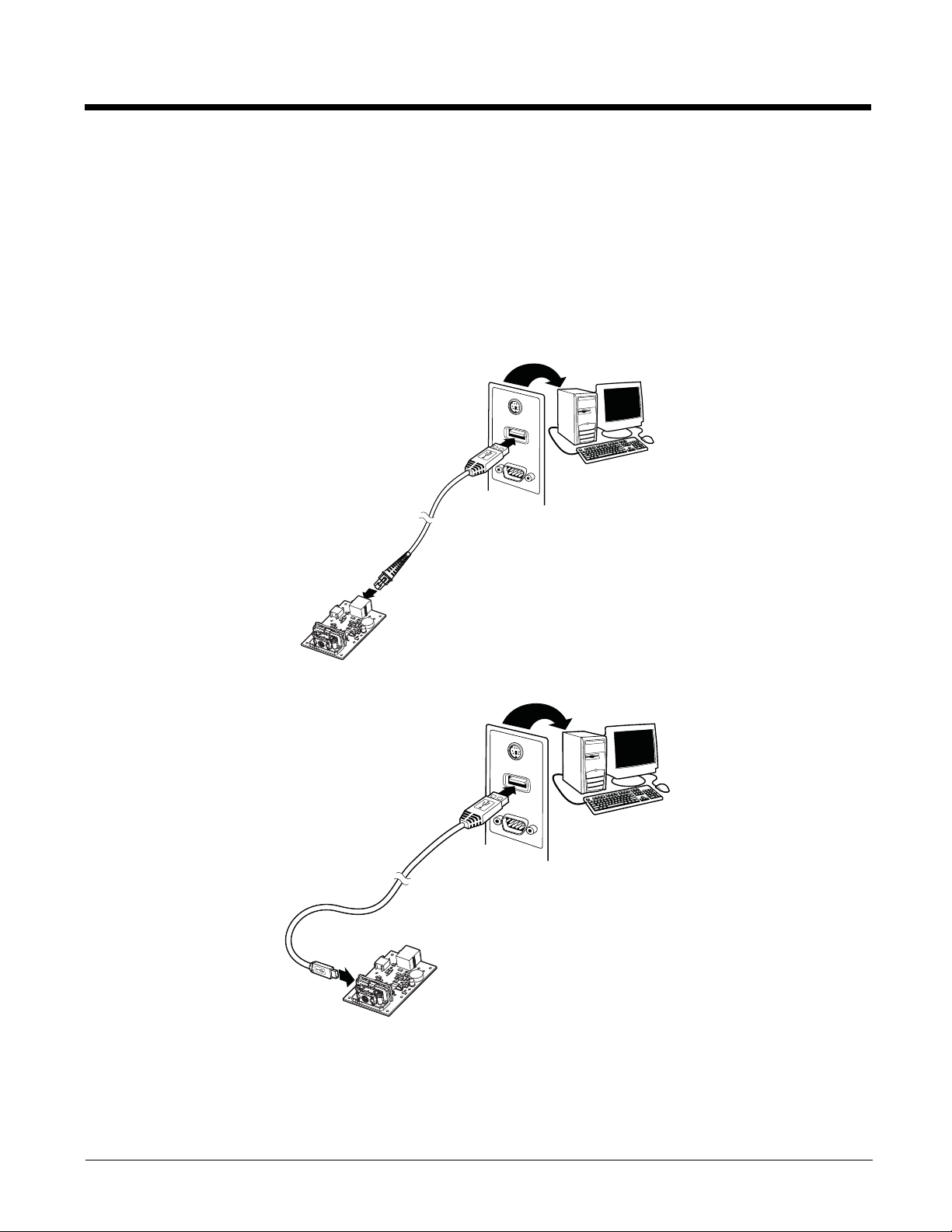
Connecting with USB
Note: If using the N56XXX-XXX-XX5 engine with USB Micro-B, do not supply power through the flex connector. Doing so
may damage the host or engine. The N56XXX-XXX-XX5 engine will only communicate USB through the Micro-B
connector. The N56XXX-XXX-XX3 engine will only communicate USB through the 10 pin modular connector.
1. Turn off power to the terminal/computer.
2. If using full-speed USB, connect the USB interface cable to the interface board and to the matching USB port on the
computer.
If using high-speed USB, connect the USB interface cable to side of the engine and to the USB port on the computer.
Note: For additional USB programming and technical information, refer to Honeywell’s “USB Application Note,” available at
www.honeywellaidc.com.
1 - 2
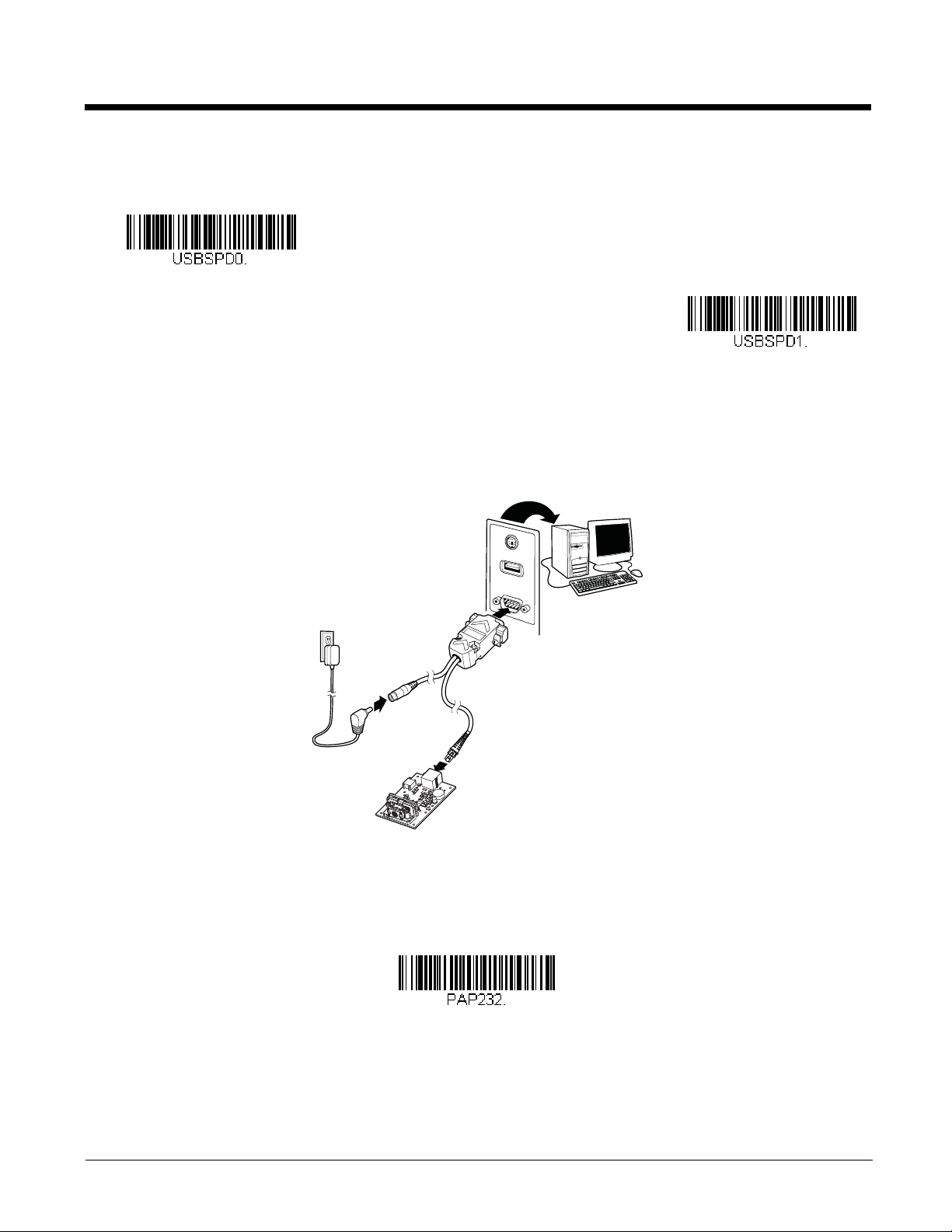
3. When connecting the engine using full-speed or high-speed USB, all communication parameters between the engine
Full-Speed USB
High-Speed USB
RS-232 Interface
and terminal must match for correct data transfer using USB protocol. Scan the appropriate USB interface bar code
below.
4. Verify the engine operation by scanning a bar code from the Sample Symbols in the back of this manual. The engine
beeps once when a bar code is successfully decoded.
Connecting with RS232 Serial Port
1. If using an RS-232 connection, connect the serial interface cable to the interface board and to the matching port on the
back of the computer.
2. Connect the power supply connector to the serial interface cable. Plug in the power supply.
3. Turn the terminal/computer power back on. The engine beeps.
4. If connecting the engine using an RS-232 interface, all communication parameters between the engine and terminal
5. Verify the engine operation by scanning a bar code from the Sample Symbols in the back of this manual. The engine
To connect an engine to your host system, refer to the N56XX Integration Manual.
must match for correct data transfer through the serial port using RS-232 protocol. Scan the RS-232 interface bar code
below. This programs the engine for an RS-232 interface at 115,200 baud, parity–none, 8 data bits, 1 stop bit, and adds
a suffix of a CR LF.
beeps once when a bar code is successfully decoded.
1 - 3

The engine has a view finder that projects a bright red aiming beam that corresponds to the engine’s horizontal field of view.
Linear bar code 2D Matrix symbol
Set Custom Defaults
Save Custom Defaults
The aiming beam should be centered over the bar code, but it can be positioned in any direction for a good read.
The aiming beam is smaller when the engine is closer to the code and larger when it is farther from the code. Symbologies with
smaller bars or elements (mil size) should be read closer to the unit. Symbologies with larger bars or elements (mil size) should
be read farther from the unit. To read single or multiple symbols (on a page or on an object), hold the engine at an appropriate
distance from the target, pull the trigger, and center the aiming beam on the symbol. If the code being scanned is highly reflective (e.g., laminated), it may be necessary to tilt the code up 15° to 18° to prevent unwanted reflection.
Menu Bar Code Security Settings
Honeywell scan engines are programmed by scanning menu bar codes or by sending serial commands to the scan engine. If
you want to restrict the ability to scan menu codes, you can use the Menu Bar Code Security settings. Please contact the nearest technical support office (see Limited Warranty on page 12-1) for further information.
Setting Custom Defaults
You have the ability to create a set of menu commands as your own, custom defaults. To do so, scan the Set Custom Defaults
bar code below before scanning the menu commands for your custom defaults. If a menu command requires scanning numeric
codes from the back cover, then a Save code, that entire sequence will be saved to your custom defaults. When you have
entered all the commands you want to save for your custom defaults, scan the Save Custom Defaults bar code.
1 - 4

You may have a series of custom settings and want to correct a single setting. To do so, just scan the new setting to overwrite
Activate Custom Defaults
the old one. For example, if you had previously saved the setting for Beeper Volume at Low to your custom defaults, and decide
you want the beeper volume set to High, just scan the Set Custom Defaults bar code, then scan the Beeper Volume High
menu code, and then Save Custom Defaults. The rest of the custom defaults will remain, but the beeper volume setting will be
updated.
Resetting the Custom Defaults
If you want the custom default settings restored to your scan engine, scan the Activate Custom Defaults bar code below. This
is the recommended default bar code for most users. It resets the scan engine to the custom default settings. If there are no
custom defaults, it will reset the scan engine to the factory default settings. Any settings that have not been specified through
the custom defaults will be defaulted to the factory default settings.
1 - 5

1 - 6

2
IBM PC AT and Compatibles with
CR suffix
Laptop Direct Connect
with CR suffix
RS232 Interface
Programming the Interface
Introduction
This chapter describes how to program your system for the desired interface.
Programming the Interface - Plug and Play
Plug and Play bar codes provide instant scanner set up for commonly used interfaces.
Note: After you scan one of the codes, power cycle the host terminal to have the interface in effect.
Keyboard Wedge
If you want your system programmed for an IBM PC AT and compatibles keyboard wedge interface with a USA keyboard,
scan the bar code below. Keyboard wedge is the default interface.
Note: The following bar code also programs a carriage return (CR) suffix.
Laptop Direct Connect
For most laptops, scanning the Laptop Direct Connect bar code allows operation of the scan engine in parallel with the
integral keyboard. The following Laptop Direct Connect bar code also programs a carriage return (CR) suffix and turns on
Emulate External Keyboard (page 2-14).
RS232 Serial Port
The RS232 Interface bar code is used when connecting to the serial port of a PC or terminal. The following RS232 Interface bar code also programs a carriage return (CR) and a line feed (LF) suffix, baud rate, and data format as indicated
below. It also changes the trigger mode to manual.
Option Setting
Baud Rate 115,200 bps
Data Format 8 data bits, no parity bit, 1 stop bit
2 - 1
USB IBM SurePos
USB IBM SurePos
(USB Handheld Scanner)
Interface
USB IBM SurePos
(USB Tabletop Scanner)
Interface
U
S
B
K
e
y
b
o
a
r
d
(
P
C
)
USB Keyboard (Mac)
USB Japanese Keyboard (PC)
USB HID Bar Code Scanner
Scan one of the following “Plug and Play” codes to program the scan engine for an IBM SurePos (USB handheld scanner)
or IBM SurePos (USB tabletop scanner) interface.
Note: After scanning one of these codes, you must power cycle the cash register.
Each bar code above also programs the following suffixes for each symbology:
Symbology Suffix Symbology Suffix
EAN 8 0C Code 39 00 0A 0B
EAN 13 16 Interleaved 2 of 5 00 0D 0B
UPC A 0D Code 128 00 18 0B
UPC E 0A Code 39 00 0A 0B
USB PC or Macintosh Keyboard
Scan one of the following codes to program the scan engine for USB PC Keyboard or USB Macintosh Keyboard. Scanning
these codes also adds a CR suffix.
USB HID
Scan the following code to program the scan engine for USB HID bar code scanners.
2 - 2

USB Serial
USB Serial
CTS/RTS Emulation On
* CTS/RTS Emulation Off
ACK/NAK Mode On
* ACK/NAK Mode Off
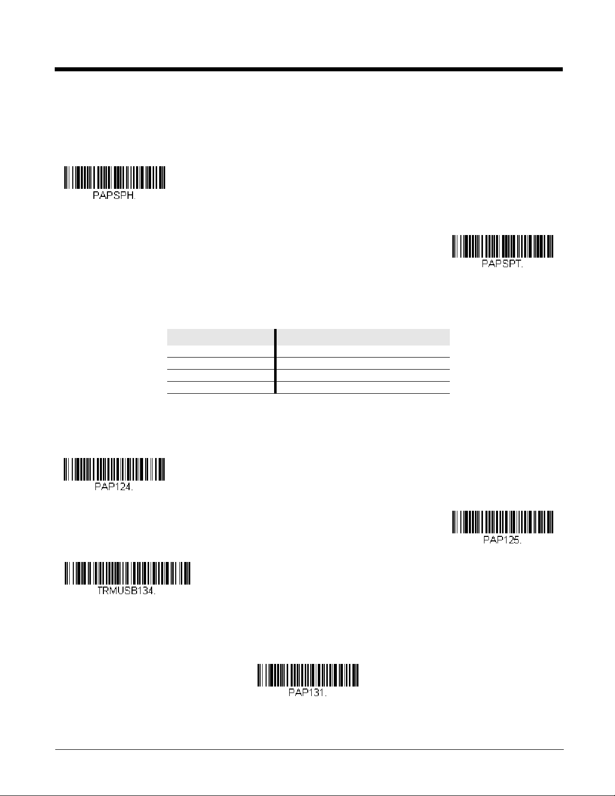
Verifone Ruby Settings
Scan the following code to program the scan engine to emulate a regular RS232-based COM Port. If you are using a Microsoft® Windows® PC, you will need to download a driver from the Honeywell website (www.honeywellaidc.com). The
driver will use the next available COM Port number. Apple® Macintosh computers recognize the scan engine as a USB
CDC class device and automatically use a class driver.
Note: No extra configuration (e.g., baud rate) is necessary.
CTS/RTS Emulation
ACK/NAK Mode
Verifone® Ruby Terminal Default Settings
Scan the following Plug and Play code to program the scan engine for a Verifone Ruby terminal. This bar code sets the
baud rate to 1200 bps and the data format to 8 data bits, no parity bit, 1 stop bit. It also adds a line feed (LF) suffix and programs the following prefixes for each symbology:
Symbology Prefix
UPC-A A
UPC-E A
EAN-8 FF
EAN-13 F
2 - 3
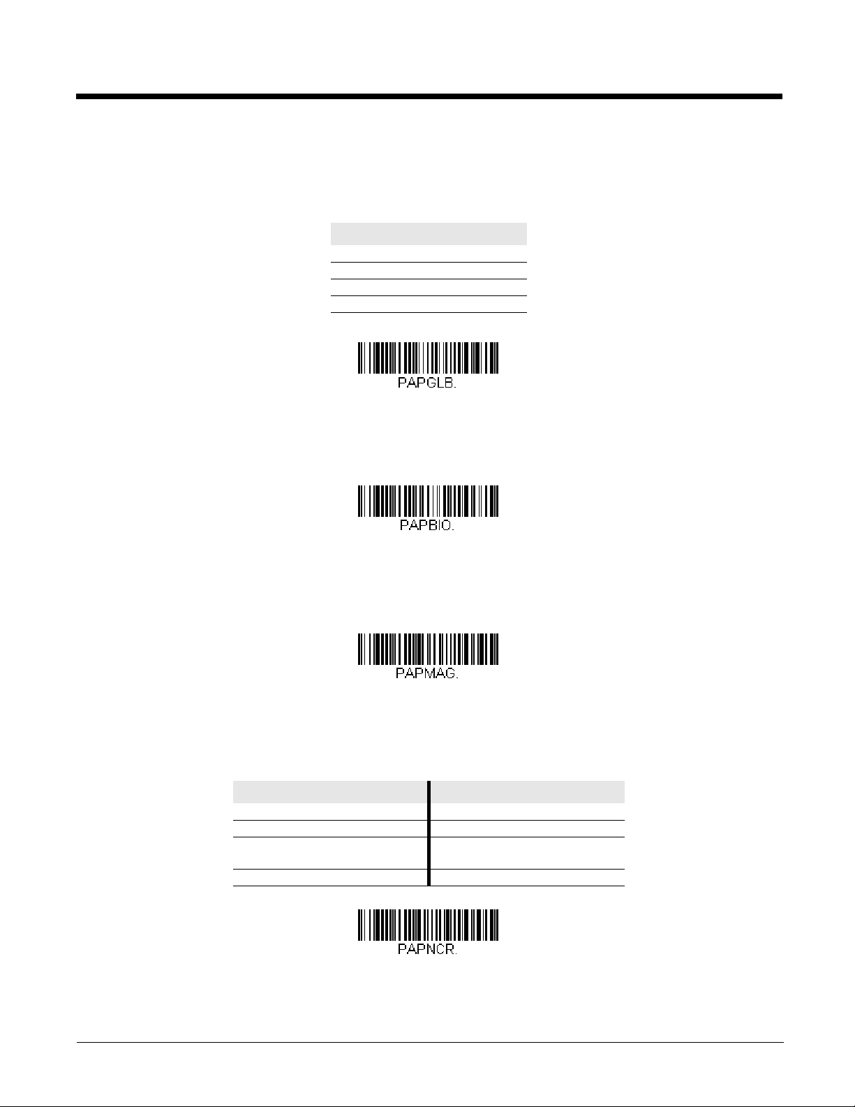
Gilbarco® Terminal Default Settings
Gilbarco Settings
Honeywell Bioptic Settings
Datalogic Magellan Settings
NCR Bioptic Settings
Scan the following Plug and Play code to program the scan engine for a Gilbarco terminal. This bar code sets the baud rate
to 2400 bps and the data format to 7 data bits, even parity, 2 stop bits. It also adds a carriage return (CR) suffix and programs the following prefixes for each symbology:
Symbology Prefix
UPC-A A
UPC-E E0
EAN-8 FF
EAN-13 F
Honeywell Bioptic Aux Port Configuration
Scan the following Plug and Play code to program the scan engine for a Honeywell bioptic scanner auxiliary port configuration. This bar code sets the baud rate to 38400 bps and the data format to 8 data bits, no parity, 1 stop bit.
Datalogic™ Magellan® Aux Port Configuration
Scan the following Plug and Play code to program the scan engine for a Datalogic Magellan auxiliary port configuration.
This bar code sets the baud rate to 9600 bps and the data format to 8 data bits, no parity, 1 stop bit.
NCR Bioptic Aux Port Configuration
Scan the following Plug and Play code to program the scan engine for an NCR bioptic scanner auxiliary port configuration.
The following prefixes are programmed for each symbology:
Symbology Prefix Symbology Prefix
UPC-A A Code 39 B1
UPC-E E0 Interleaved 2 of 5 B2
EAN-8 FF All other bar
codes
EAN-13 F
B3
2 - 4
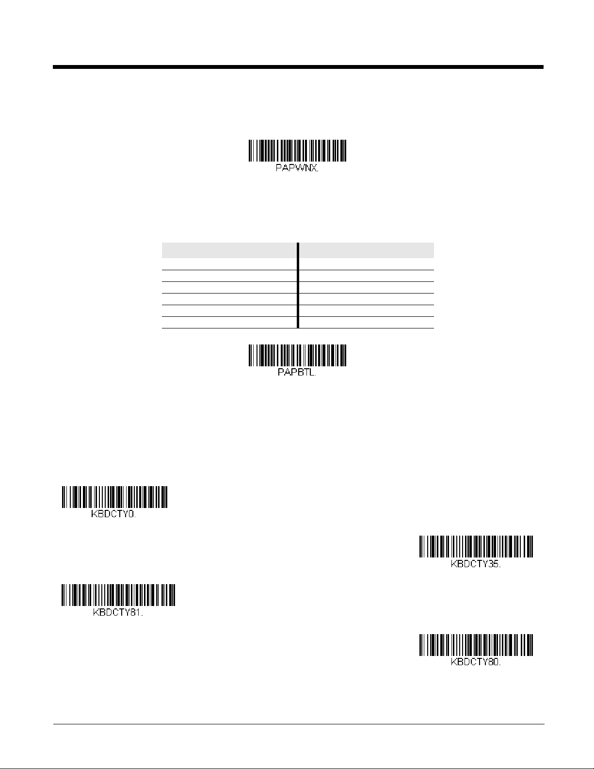
Wincor Nixdorf Terminal Default Settings
Wincor Nixdorf Terminal Settings
Wincor Nixdorf Beetle Settings
* United States
Albania
Azeri (Cyrillic)
Azeri (Latin)
Scan the following Plug and Play code to program the scan engine for a Wincor Nixdorf terminal. This bar code sets the
baud rate to 9600 bps and the data format to 8 data bits, no parity, 1 stop bit.
Wincor Nixdorf Beetle™ Terminal Default Settings
Scan the following Plug and Play code to program the scan engine for a Wincor Nixdorf Beetle terminal. The following prefixes are programmed for each symbology:
Symbology Prefix Symbology Prefix
Code 128 K EAN-13 A
Code 93 L GS1-128 P
Codabar N Interleaved 2 of 5 I
UPC-A A0 Straight 2 of 5 IATA H
UPC-E C All other bar codes M
EAN-8 B
Keyboard Country Layout
Scan the appropriate country code below to program the keyboard layout for your country or language. As a general rule, the
following characters are supported, but need special care for countries other than the United States:
@ | $ # { } [ ] = / ‘ \ < > ~
Keyboard Countries
2 - 5

Keyboard Countries (Continued)
Belarus
Belgium
Bosnia
Brazil
Brazil (MS)
Bulgaria (Cyrillic)
Bulgaria (Latin)
Canada (French legacy)
Canada (French)
Canada (Multilingual)
Croatia
2 - 6

Keyboard Countries (Continued)
Czech
Czech (Programmers)
Czech (QWERTY)
Czech (QWERTZ)
Denmark
Dutch (Netherlands)
Estonia
Faroese
Finland
France
Gaelic
2 - 7

Keyboard Countries (Continued)
Germany
Greek
Greek (220 Latin)
Greek (220)
Greek (319 Latin)
Greek (319)
Greek (Latin)
Greek (MS)
Greek (Polytonic)
Hebrew
Hungarian (101 key)
2 - 8

Keyboard Countries (Continued)
Hungary
Iceland
Irish
Italian (142)
Italy
Japan ASCII
Kazakh
Kyrgyz (Cyrillic)
Latin America
Latvia
Latvia (QWERTY)
2 - 9

Keyboard Countries (Continued)
Lithuania
Lithuania (IBM)
Macedonia
Malta
Mongolian (Cyrillic)
Norway
Poland
Polish (214)
Polish (Programmers)
Portugal
Romania
2 - 10

Keyboard Countries (Continued)
Russia
Russian (MS)
Russian (Typewriter)
SCS
Serbia (Cyrillic)
Serbia (Latin)
Slovakia
Slovakia (QWERTY)
Slovakia (QWERTZ)
Slovenia
Spain
2 - 11

Keyboard Countries (Continued)
Spanish variation
Sweden
Switzerland (French)
Switzerland (German)
Tatar
Turkey F
Turkey Q
Ukrainian
United Kingdom
United States (Dvorak)
United States (Dvorak left)
2 - 12

Keyboard Countries (Continued)
United Stated (Dvorak right)
United States (International)
Uzbek (Cyrillic)
* Regular
Caps Lock
Shift Lock
Automatic Caps Lock
Autocaps via NumLock
Keyboard Style
This programs keyboard styles, such as Caps Lock and Shift Lock. If you have used Keyboard Conversion settings, they will
override any of the following Keyboard Style settings. Default = Regular.
Regular is used when you normally have the Caps Lock key off.
Caps Lock is used when you normally have the Caps Lock key on.
Shift Lock is used when you normally have the Shift Lock key on (not common to U.S. keyboards).
Automatic Caps Lock is used if you change the Caps Lock key on and off. The software tracks and reflects if you have Caps
Lock on or off . This selection can only be used with systems that have an LED that notes the Caps Lock status (AT keyboards).
Autocaps via NumLock bar code should be scanned in countries (e.g., Germany, France) where the Caps Lock key cannot be
used to toggle Caps Lock. The NumLock option works similarly to the regular Autocaps, but uses the NumLock key to retrieve
the current state of the Caps Lock.
2 - 13

Emulate External Keyboard should be scanned if you do not have an external keyboard (IBM AT or equivalent).
Emulate External Keyboard
* Keyboard Conversion Off
Convert All Characters
to Upper Case
Convert All Characters
to Lower Case
Control Character Output On
* Control Character Output Off
Note: After scanning the Emulate External Keyboard bar code, you must power cycle your computer.
Keyboard Conversion
Alphabetic keyboard characters can be forced to be all upper case or all lowercase. So if you have the following bar code:
“abc569GK,” you can make the output “ABC569GK” by scanning Convert All Characters to Upper Case, or to “abc569gk” by
scanning Convert All Characters to Lower Case.
These settings override Keyboard Style selections.
Note: If your interface is a keyboard wedge, first scan the menu code for Automatic Caps Lock (page 2-13). Otherwise, your
output may not be as expected.
Default = Keyboard Conversion Off.
Control Character Output
This selection sends a text string instead of a control character. For example, when the control character for a carriage return is
expected, the output would display [CR] instead of the ASCII code of 0D. Refer to ASCII Conversion Chart (Code Page
1252) on page A-3. Only codes 00 through 1F are converted (the first column of the chart).
Note: Control + X (Control + ASCII) Mode overrides this mode.
Default = Off.
2 - 14
 Loading...