

Honeywell 550-850 User Manual
N
B
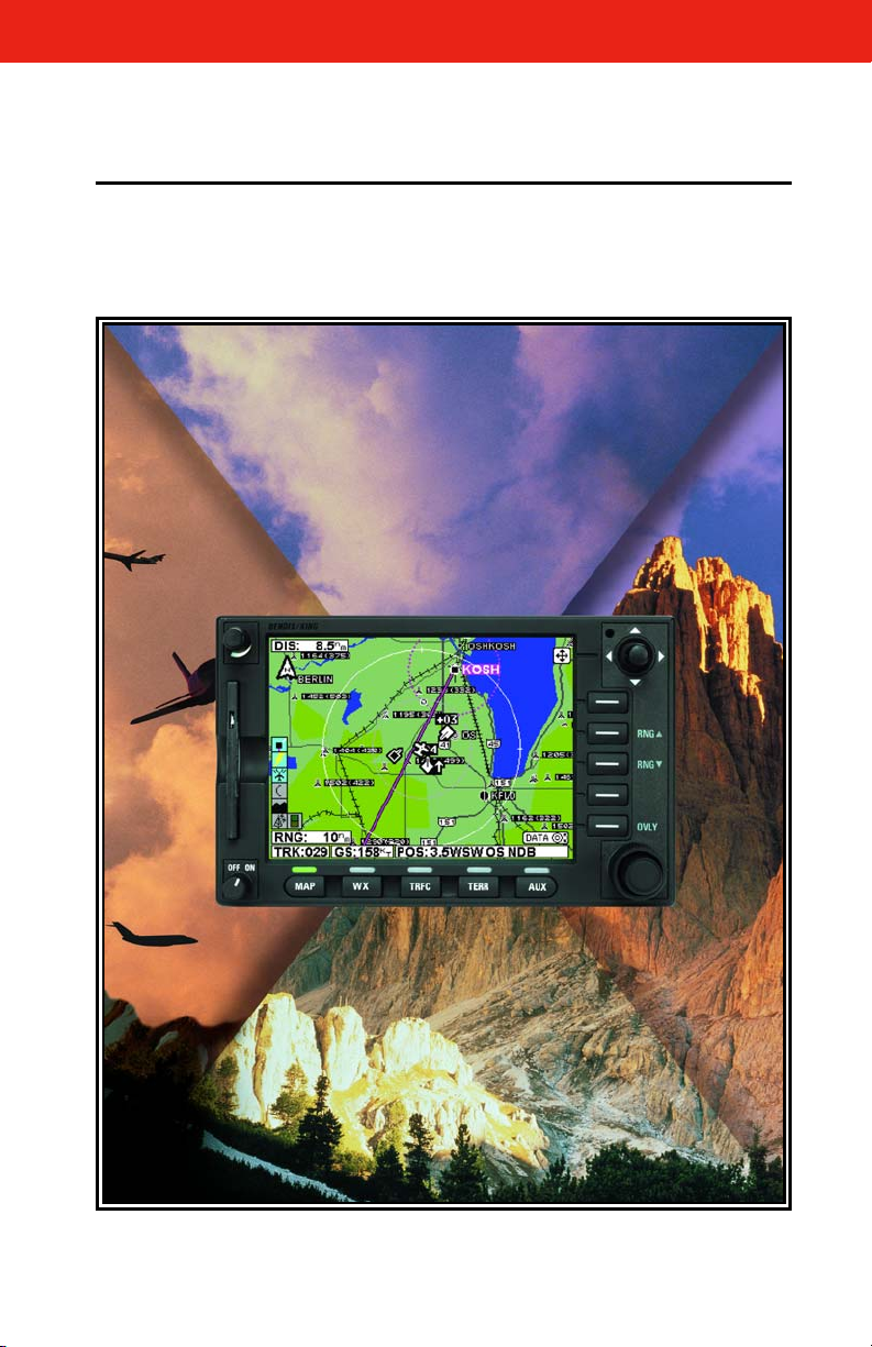
KMD 550/850
Multi-Function Display
Pilot’s Guide
For Software Version 02/01 or later
Revision 8 Mar/2007
006-18222-0000

The information contained in this manual is for reference use only. If
any information contained herein conflicts with similar information
contained in the Airplane Flight Manual Supplement, the information in
the Airplane Flight Manual Supplement shall take precedence.
Covered by US Pat. 6512975
WARNING
Prior to export of this document, review for export license requirement is
needed.
COPYRIGHT NOTICE
Copyright ©2000 - 2005, 2007 Honeywell International Inc.
All rights reserved.
Reproduction of this publication or any portion thereof by any means without
the express written permission of Honeywell International Inc. is prohibited.
For further information contact the Manager, Technical Publications;
Honeywell International Inc.; One Technology Center; 23500 West 105th
Street; Olathe, Kansas 66061. Telephone: (913) 712-0400.

Revision History
Manual KMD 550/850 Pilot’s Guide
Revision 8, March 2007
Part Number 006-18222-0000
Summary
Added XM functionality
Added DTK readout on Map page
Updated SUA boundary labels
R-1

Revision History
Manual KMD 550/850 Pilot’s Guide
Revision 7, September 2005
Part Number 006-18222-0000
Summary
Changed Stormscope®to registered trademark
Updated displays
Miscellaneous corrections
R-2

Revision History
Manual KMD 550/850 Pilot’s Guide
Revision 6, June 2004
Part Number 006-18222-0000
Summary
Changed lightning symbols to white
Changed airspace classifications
Changed display color for Danger, Prohibited and Restricted
Airspace
Added black border to active flight plan leg display
Updated startup pages
Miscellaneous corrections
R-3

Revision History
Manual KMD 550/850 Pilot’s Guide
Revision 5, January 2003
Part Number 006-18222-0000
Summary
Complete manual revision
R-4

Revision History
Manual KMD 550/850 Pilot’s Guide
Revision 4, January 2003
Part Number 006-18222-0000
Summary
Complete manual revision
R-5

Revision History
Manual KMD 550/850 Pilot’s Guide
Revision 3, May 2002
Part Number 006-18222-0000
Summary
Complete manual revision
R-6

Revision History
Manual KMD 550/850 Pilot’s Guide
Revision 2, November 2001
Part Number 006-18222-0000
Summary
Improved display of traffic overlay on the Map Page
Small Traffic Window is no longer displayed when the Map Page is in
the north-up orientation.
The Map Setup Page may be configured to be inaccessible to the .
operator
Inner and outer knobs are enabled to select airport information from
the Map Page by entering identifier, name or city
R-7

Revision History
Manual KMD 550/850 Pilot’s Guide
Revision 1, April 2001
Part Number 006-18222-0000
Summary
Revised Database Warning Page
Added GCO frequencies to Airport MORE INFO Window
Added Heliroutes and Helipads to Map Page
Airplane symbol now oriented to heading on Map Page
Added traffic display functions
Changed lightning symbols and Function Display Icon for strikes with
in 25 nm
Corrected miscellaneous errors
R-8

Revision History
Manual KMD 550/850 Pilot’s Guide
Revision 0, October 2000
Part Number 006-18222-0000
Summary
This is the original release of this publication.
R-9

This page intentionally left blank.
R-10

Table of Contents
INTRODUCTION . . . . . . . . . . . . . . . . . . . . . . . . . . . . . . . . . . . . . . . . . . . . . . .1
GENERAL INFORMATION . . . . . . . . . . . . . . . . . . . . . . . . . . . . . . . . . . . . .3
FUNCTION SELECT KEYS . . . . . . . . . . . . . . . . . . . . . . . . . . . . . . . . . . .4
POWER KEYS . . . . . . . . . . . . . . . . . . . . . . . . . . . . . . . . . . . . . . . . . . . .4
POWER LABELS . . . . . . . . . . . . . . . . . . . . . . . . . . . . . . . . . . . . . . . . . .4
SOFT LABELS . . . . . . . . . . . . . . . . . . . . . . . . . . . . . . . . . . . . . . . . . . . .5
JOYSTICK . . . . . . . . . . . . . . . . . . . . . . . . . . . . . . . . . . . . . . . . . . . . . . .5
CONTROL KNOB . . . . . . . . . . . . . . . . . . . . . . . . . . . . . . . . . . . . . . . . . .5
FAULT INDICATOR . . . . . . . . . . . . . . . . . . . . . . . . . . . . . . . . . . . . . . . . .5
STORMSCOPE®OPTION . . . . . . . . . . . . . . . . . . . . . . . . . . . . . . . . . . . .7
OBSTACLE LABELS . . . . . . . . . . . . . . . . . . . . . . . . . . . . . . . . . . . . . . . .7
MAP TOPOGRAPHIC AND URBAN AREAS DISPLAY . . . . . . . . . . . . . . .7
STARTUP DISPLAY . . . . . . . . . . . . . . . . . . . . . . . . . . . . . . . . . . . . . . . .8
POP-UP HELP DISPLAYS . . . . . . . . . . . . . . . . . . . . . . . . . . . . . . . . . . .8
OPERATION . . . . . . . . . . . . . . . . . . . . . . . . . . . . . . . . . . . . . . . . . . . . . . . .9
SELECTING A MAP DISPLAY . . . . . . . . . . . . . . . . . . . . . . . . . . . . . . . . .9
USING THE MAP . . . . . . . . . . . . . . . . . . . . . . . . . . . . . . . . . . . . . . . . . .9
Data Interrogation . . . . . . . . . . . . . . . . . . . . . . . . . . . . . . . . . . . . . .11
Airport Information . . . . . . . . . . . . . . . . . . . . . . . . . . . . . . . . . . . . .12
Navaid Information . . . . . . . . . . . . . . . . . . . . . . . . . . . . . . . . . . . . .16
General Icon Information . . . . . . . . . . . . . . . . . . . . . . . . . . . . . . . . .16
Airspace Interrogation . . . . . . . . . . . . . . . . . . . . . . . . . . . . . . . . . . .17
Display Flight Plan Data . . . . . . . . . . . . . . . . . . . . . . . . . . . . . . . . . .17
OVERLAYING DATA . . . . . . . . . . . . . . . . . . . . . . . . . . . . . . . . . . . . . . .18
DISPLAYING WEATHER RADAR (KMD 850 ONLY), STORMSCOPE
OR FLIGHT INFORMATION SERVICES . . . . . . . . . . . . . . . . . . . . . . . . .19
DISPLAYING TRAFFIC . . . . . . . . . . . . . . . . . . . . . . . . . . . . . . . . . . . . .19
SELECTING ENHANCED GROUND PROXIMITY WARNING SYSTEM . .19
VIDEO DISPLAY . . . . . . . . . . . . . . . . . . . . . . . . . . . . . . . . . . . . . . . . . .19
Rev 8 Mar/2007
i
KMD 550/850 Pilot's Guide
®

Table of Contents
SYSTEM SETUP . . . . . . . . . . . . . . . . . . . . . . . . . . . . . . . . . . . . . . . . . . . .21
INTRODUCTION . . . . . . . . . . . . . . . . . . . . . . . . . . . . . . . . . . . . . . . . . .21
MAP SETUP . . . . . . . . . . . . . . . . . . . . . . . . . . . . . . . . . . . . . . . . . . . . .21
WX-500 STORMSCOPE®SETUP . . . . . . . . . . . . . . . . . . . . . . . . . . . . .24
DATA CARDS . . . . . . . . . . . . . . . . . . . . . . . . . . . . . . . . . . . . . . . . . . . . . .27
DATA AREAS . . . . . . . . . . . . . . . . . . . . . . . . . . . . . . . . . . . . . . . . . . . .27
CHANGING THE DATA CARD . . . . . . . . . . . . . . . . . . . . . . . . . . . . . . . .28
DATABASE INFORMATION . . . . . . . . . . . . . . . . . . . . . . . . . . . . . . . . .28
DATABASE CYCLE INFORMATION . . . . . . . . . . . . . . . . . . . . . . . . . . . .28
DEFINITIONS, ACRONYMS AND ABBREVIATIONS . . . . . . . . . . . . . . . . .29
DEFINITIONS . . . . . . . . . . . . . . . . . . . . . . . . . . . . . . . . . . . . . . . . . . . .29
ACRONYMS AND ABBREVIATIONS . . . . . . . . . . . . . . . . . . . . . . . . . . .30
WX-500 STORMSCOPE®OPERATION . . . . . . . . . . . . . . . . . . . . . . . . . .35
INTRODUCTION . . . . . . . . . . . . . . . . . . . . . . . . . . . . . . . . . . . . . . . . . .35
FUNCTIONAL DESCRIPTION . . . . . . . . . . . . . . . . . . . . . . . . . . . . . . . .35
OPERATION . . . . . . . . . . . . . . . . . . . . . . . . . . . . . . . . . . . . . . . . . . . . .35
Selecting Stormscope®or Weather Radar . . . . . . . . . . . . . . . . . . .35
Power-up . . . . . . . . . . . . . . . . . . . . . . . . . . . . . . . . . . . . . . . . . . . . .36
Heading Stabilization . . . . . . . . . . . . . . . . . . . . . . . . . . . . . . . . . . . .36
Clear All Discharge Points . . . . . . . . . . . . . . . . . . . . . . . . . . . . . . . .36
Switch Between Weather Views . . . . . . . . . . . . . . . . . . . . . . . . . . . .36
Switch Between Display Modes . . . . . . . . . . . . . . . . . . . . . . . . . . . .37
Cell Display Mode . . . . . . . . . . . . . . . . . . . . . . . . . . . . . . . . . . . .37
Strike Display Mode . . . . . . . . . . . . . . . . . . . . . . . . . . . . . . . . . . .38
Changing Display Range . . . . . . . . . . . . . . . . . . . . . . . . . . . . . . . . .38
Operation in Stormscope®Mode with Flight Plan Overlay . . . . . . .39
Operation in Map Display . . . . . . . . . . . . . . . . . . . . . . . . . . . . . . . . .39
®
WX-1000E STORMSCOPE
INTRODUCTION . . . . . . . . . . . . . . . . . . . . . . . . . . . . . . . . . . . . . . . . . .41
Rev 8 Mar/2007
OPERATION . . . . . . . . . . . . . . . . . . . . . . . .41
ii
KMD 550/850 Pilot's Guide

Table of Contents
FUNCTIONAL DESCRIPTION . . . . . . . . . . . . . . . . . . . . . . . . . . . . . . . .41
OPERATION . . . . . . . . . . . . . . . . . . . . . . . . . . . . . . . . . . . . . . . . . . . . .41
Selecting Stormscope®or Weather Radar . . . . . . . . . . . . . . . . . . .42
Power-up . . . . . . . . . . . . . . . . . . . . . . . . . . . . . . . . . . . . . . . . . . . . .42
Switch Between Weather Views . . . . . . . . . . . . . . . . . . . . . . . . . . . .42
Changing Display Range . . . . . . . . . . . . . . . . . . . . . . . . . . . . . . . . .42
Operation in Stormscope®Mode with Flight Plan Overlay . . . . . . .43
Operation in Map Display . . . . . . . . . . . . . . . . . . . . . . . . . . . . . . . . .43
APPENDIX A, DISPLAY ICONS . . . . . . . . . . . . . . . . . . . . . . . . . . . . . . . .A-1
Rev 8 Mar/2007
iii
KMD 550/850 Pilot's Guide

Table of Contents
Intentionally left blank
Rev 8 Mar/2007
iv
KMD 550/850 Pilot's Guide

Introduction
INTRODUCTION
All of us at Honeywell congratulate you on choosing this product. You
are now the owner of one of the most sophisticated yet simple-to-use
multifunction displays available today. We understand you probably
can’t wait to see it in action but before you try to use it please take the
time to read through this manual and understand its many interesting
and useful features. Time spent in familiarizing yourself with your new
KMD 550/850 unit will be more than repaid by trouble-free operation
later, and more importantly safe and accurate navigation.
We have made the operation of this unit as intuitive as possible through
the use of Power Keys and on-screen help, thus reducing pilots’ dependence on the manual. You should very quickly find that handling it efficiently and expertly becomes second nature to you. Don’t be afraid to
experiment. No matter which key you activate, your unit will not be damaged. If you do get into a mess, simply switch off and back on again to
reset all functions. We must mention just one word of caution. Never
remove the database card while the unit is switched on and never
attempt to switch the unit on when there is no database card
installed.
We thank you for your decision to purchase a KMD 550/850 and wish
you many happy and safe hours flying.
Whenever you are using the unit for navigation in the air you should treat
it as a supplemental display system. You should always carefully compare indications from your KMD 550/850 unit with the information available from all other navigation sources including GPS, NDBs, VORs,
DMEs, visual sightings, charts, etc. For safety, any discrepancies
observed should be resolved immediately.
This equipment is not a replacement for your chart. It is intended as an
aid to navigation only. The database within the equipment has been
compiled from the latest official information available, and although
every care has been taken in the compilation, the manufacturers will not
be held responsible for any inaccuracy or omissions therein. NEVER
USE THE TERRAIN DISPLAYED ON THIS EQUIPMENT AS YOUR
SOLE REFERENCE FOR TERRAIN AVOIDANCE.
Rev 7 Sep/2005 KMD 550/850 Pilot's Guide
1

Introduction
Intentionally left blank
Rev 5 Jan/2003
2
KMD 550/850 Pilot's Guide
General Information
GENERAL INFORMATION
This section of the manual provides an overview of the software architecture and display presentation of the KMD 550/850 Multifunction Display.
This manual also provides an explanation of each of the individual displays that the KMD 550/850 unit presents.
The operating system of the Bendix/King KMD 550/850 keeps to a minimum the number of key presses necessary to activate the various functions, especially those most frequently used in the air. The provision of a
joystick makes it considerably easier to operate the unit and allows for
fast and efficient access to most functions.
12
1
2
3
10
4
6
11
13
F
9
5
8
7
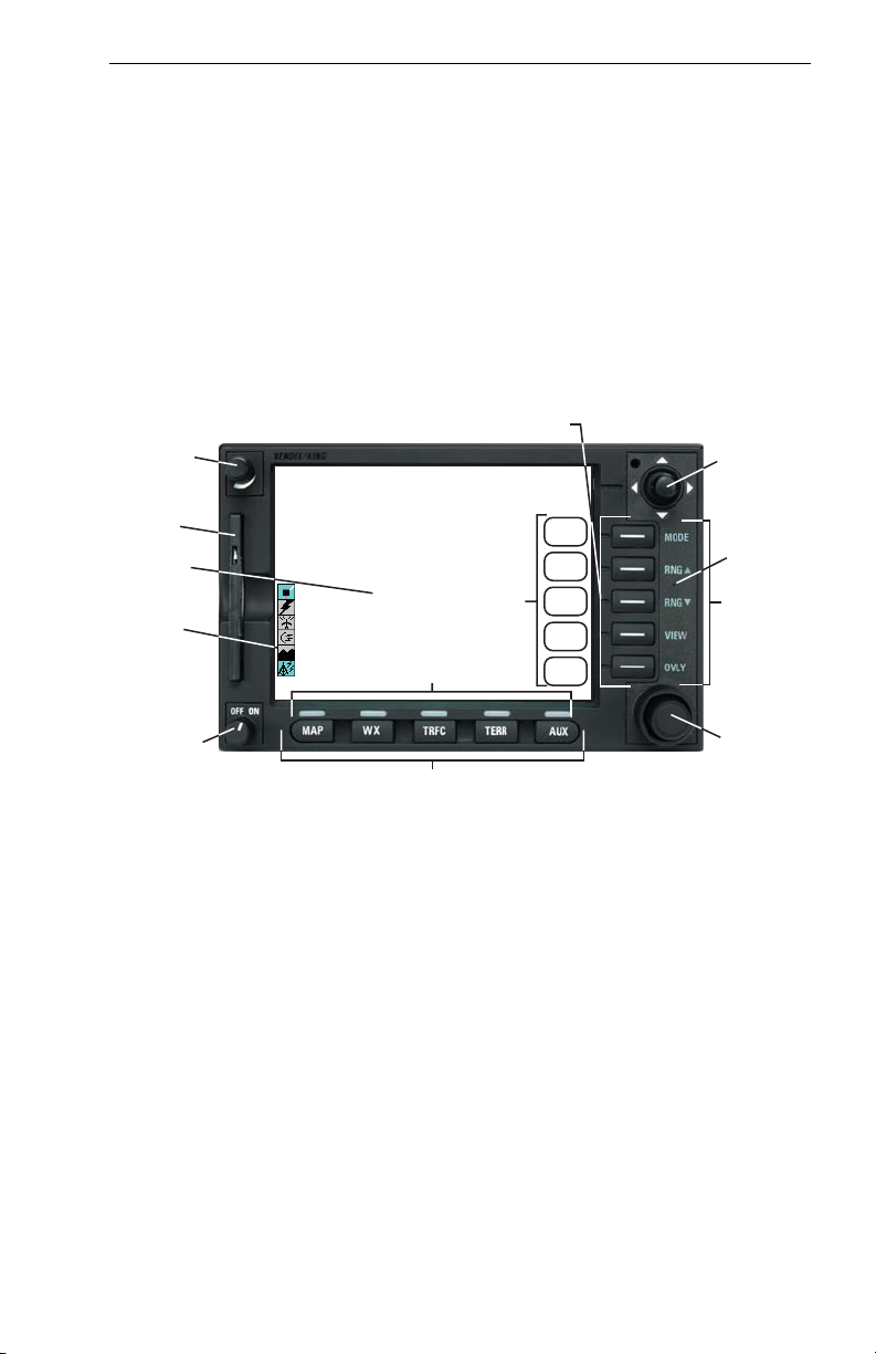
1. Brightness Control
2. Data Card
3. Display
4. Available Functions Legend
5. On/Off Control
6. Function Select Indicators
7. Function Select Keys
8. Control Knobs (Inner and Outer Knob)
9. Power Labels
10. Soft Labels
11. Joystick
12. Power Keys
13. Fault Indicator
See Appendix A for a description of Functions Legend and map display
icons.
Rev 5 Jan/2003 KMD 550/850 Pilot's Guide
3

General Information
FUNCTION SELECT KEYS
These keys are used to select available data sources (as indicated on
the key) for display on the LCD. When a function key is pressed, the
annunciator above it will illuminate to show that this function is presently
being displayed. Pressing the same Function Select Key multiple times
will sequence through the available pages associated with that function.
The following diagram shows the available pages under each function.
Note that not all pages will be available in all installations.
WX TRFC TERR AUXMAP
Topo On
Map
Topo Off
Map
WX Radar*
Stormscope
Datalink Wx
Graphical
Products
Datalink Wx
Textual
Products
TAS/TCAS/TIS
* KMD 850 Only
EGPWS
Setup Pages
External
NTSC Video
POWER KEYS
These five keys are used to manipulate the page being displayed. Their
present functionality can be indicated by the use of Soft Labels on the
left side of the key or Power Labels on the right side of the key.
POWER LABELS
When the Power Label is illuminated on the right side of the key, that
key’s function is dedicated to the function described by the label and that
function is active. The following is a list of the dedicated functions:
MODE- Pressing this key will sequence through all available modes
associated with the displayed page.
RNGΔ- Pressing this key will increase the range scale one level on
the displayed page. Range scales on other pages will not
be affected.
RNG∇- Pressing this key will decrease the range scale one level on
the displayed page. Range scales on other pages will not
be affected.
VIEW- Pressing this key will sequence through the available views
associated with the displayed page.
Rev 8 Mar/2007
4
KMD 550/850 Pilot's Guide

General Information
OVLY- Pressing the Overlay Key allows data from more than one
source to be displayed simultaneously on the display. Soft
Labels will indicate which data sources are available for
overlay.
SOFT LABELS
Soft Labels are located to the left of the Power Keys in the LCD area.
The description indicated in the label describes the key’s present function related to the displayed page. Whenever a new function is selected,
by pressing a key with a Soft Label, a new display is shown along with its
new key labels. This capability of displaying Soft Labels that are only
applicable to a particular screen is referred to as ‘Soft Keying’, and
allows one key to perform multiple functions without the complications of
multiple key presses on a conventional keypad.
JOYSTICK
This is a pointing device which moves a mouse-like pointer around the
display. It is primarily used for pointing at items on the map for further
information and for measuring range and bearing to specific points.
When the WX Radar function is selected, the joystick controls antenna
tilt angle and track. Data link weather also uses the joystick to perform
product display selection. It is also used to modify configuration settings
on the AUX setup pages.
CONTROL KNOB
The inner and outer Control Knobs, located in the lower right of the unit,
have various functions as indicated by a soft label when active. For
example, if the weather (WX) Function Select Key is pressed, the inner
knob may control the gain on the weather radar. The outer knob will act
as the radar function selector for ON, Standby (SBY) and Test (TST).
Data link weather also uses the joystick to do product display selection.
FAULT INDICATOR
The Fault Indicator is located between the Range buttons. If this tiny “F”
is illuminated, a system hardware problem is exists. This could be
caused by the unit failing a self test or an improper installation configuration.
If the Fault Indicator appears, cycle the unit power. If the fault re-occurs,
the unit needs to be taken to an authorized service center to correct the
configuration or repair the unit.
Rev 8 Mar/2007 KMD 550/850 Pilot's Guide
5
 Loading...