

Honeywell 51454941 User Manual

ISA100 Gen X Radio Module
User's Guide
Release Independent
April 2018
Honeywell

ISA100 Gen X Radio Module User's Guide
Honeywell
Release Independent
April 2018
Document Name
Version No.
Release Number
Publication Date
ISA100 Gen X Radio Module User's Guide
1.0
Release Independent
April 2018
Contact:
Phone:
Honeywell Technology
Solutions Lab ACS
Wireless COE Survey No.
19/2 Adarsh Prime Project
Pvt. Ltd
Devarabisanahalli,
Varthur Hobli, Bangalore
East Taluk, 91-8026588360
Release Information
Contact Information
ii

Release Independent
April 2018
ISA100 Gen X Radio Module User's Guide
Honeywell
Acronyms and Definitions
Acronym
Definition
DSSS
Direct-sequence spread spectrum
SPI
Serial peripheral interface
GND
Ground
EIRP
Equivalent isotopically radiated power
WCI
Wireless Compliance Institute
TCXO
Temperature Control Crystal Oscillator
SDR
Sensor Data Ready
CS
Chip Select
DAP
Device Application Process
DD
Device Description – a formal description of device objects used by
host system tools.
DMAP
Device Management Application Process
UAP
User Application Process
AI
Analog Input
BI
Binary Input
UAPMO
User Application Process Management Object
APDU
Application Process Data Unit
RSSI
Received Signal Strength Indicator
RSQI
Received Signal Quality Indicator
EEPROM
Electrically Erasable Programmable Read Only Memory
LCD
Liquid Crystal Display
GPIO
General Purpose Input Output
iii

ISA100 Gen X Radio Module User's Guide
Honeywell
Release Independent
April 2018
ASL
Application Service Layer
UDO
Upload Download Object
LPM
Low Power Mode
CRC
Cyclic Redundancy Code
PHY
Physical
DLL
Data Link layer
SAP
Service Access Point
NL
Network Layer
TL
Transport Layer
DPO
Data Process Object
DMO
Data Management Object
ISA
International Society of Automation
Acronym Definition
iv

Release Independent
April 2018
ISA100 Gen X Radio Module User's Guide
Honeywell
CONTENTS
1 INTRODUCTION.................................................................................................................... 10
1.1 Overview ....................................................................................................................................................... 10
2 SPECIFICATIONS.................................................................................................................. 12
2.1 Features ........................................................................................................................................................ 12
2.2 Electrical requirements ................................................................................................................................ 12
2. 3 Types of Antenna ......................................................................................................................................... 12
2.4 Transmitter Power Configuration ................................................................................................................ 14
3 CONNECTOR DETAILS ....................................................................................................... 15
3.1 Debug Connector Details .......................................................................................................................... 15
3.2 Sensor-Radio Interface Connector Details ................................................................................................... 19
4 ARCHITECTURAL OVERVIEW ........................................................................................ 22
5. SPI COMMUNICATION BETWEEN THE ISA100 RADIO AND THE SENSOR
BOARD ........................................................................................................................................ 24
5.1 SPI Configuration ......................................................................................................................................... 24
5.2 Inter-Processor Interface .............................................................................................................................. 27
5.3 Inter Processor Communication Packet description .................................................................................... 28
6. MESSAGE FLOW BETWEEN THE RADIO AND SENSOR ....................................... 45
6.1 Start-up Mode ............................................................................................................................................... 45
6.2 Normal Mode ................................................................................................................................................ 45
7. SAMPLE CODE DESCRIPTION ..................................................................................... 47
7.1 Scheduler ...................................................................................................................................................... 47
7.2 Interrupts ...................................................................................................................................................... 47
7.3 ISA100 Objects ............................................................................................................................................. 48
v

ISA100 Gen X Radio Module User's Guide
Honeywell
Release Independent
April 2018
7.4 Device Drivers ............................................................................................................................................... 49
7.5 Alert Configuration and Reporting .............................................................................................................. 50
8. MECHANICAL DRAWING OF ISA100 RADIO MODULE ........................................ 59
9 POWER LEVEL SETTINGS FOR FCC AND IC ................................................................................... 61
APPENDIX A: COMPLIANCE STATEMENTS.................................................................... 62
A.1 FCC Compliance Statements ....................................................................................................................... 62
A.2
IC Compliance Statements .................................................................................................................... 63
A.3
Software Compliance ............................................................................................................................. 65
APPENDIX B: AGENCY LABEL INFORMATION ............................................................. 66
B.1
FCC/IC Labels ....................................................................................................................................... 66
APPENDIX C: PROGRAMMING GXRM.............................................................................. 68
C.1 Introduction ................................................................................................................................................. 68
C.2 Software Configuration ............................................................................................................................... 68
vi

Release Independent
April 2018
ISA100 Gen X Radio Module User's Guide
Honeywell
Tables
Table 1 Antenna Types ............................................................................................................................... 13
Table 2 Transmit Power Settings ................................................................................................................ 14
Table 3 Pin Details of Radio Sensor Interface Connector ........................................................................... 21
Table 4 ASL Queued Packet Types ............................................................................................................. 33
Table 5 Stack Specific Packet Types ........................................................................................................... 34
Table 6 Five Objects of the Sensor Firmware ............................................................................................. 48
Table 7 Detailed Device Status ................................................................................................................... 51
Table 8 Antenna and power level Settings FCC………………..………………………………………….61
vii

ISA100 Gen X Radio Module User's Guide
Honeywell
Release Independent
April 2018
Figures
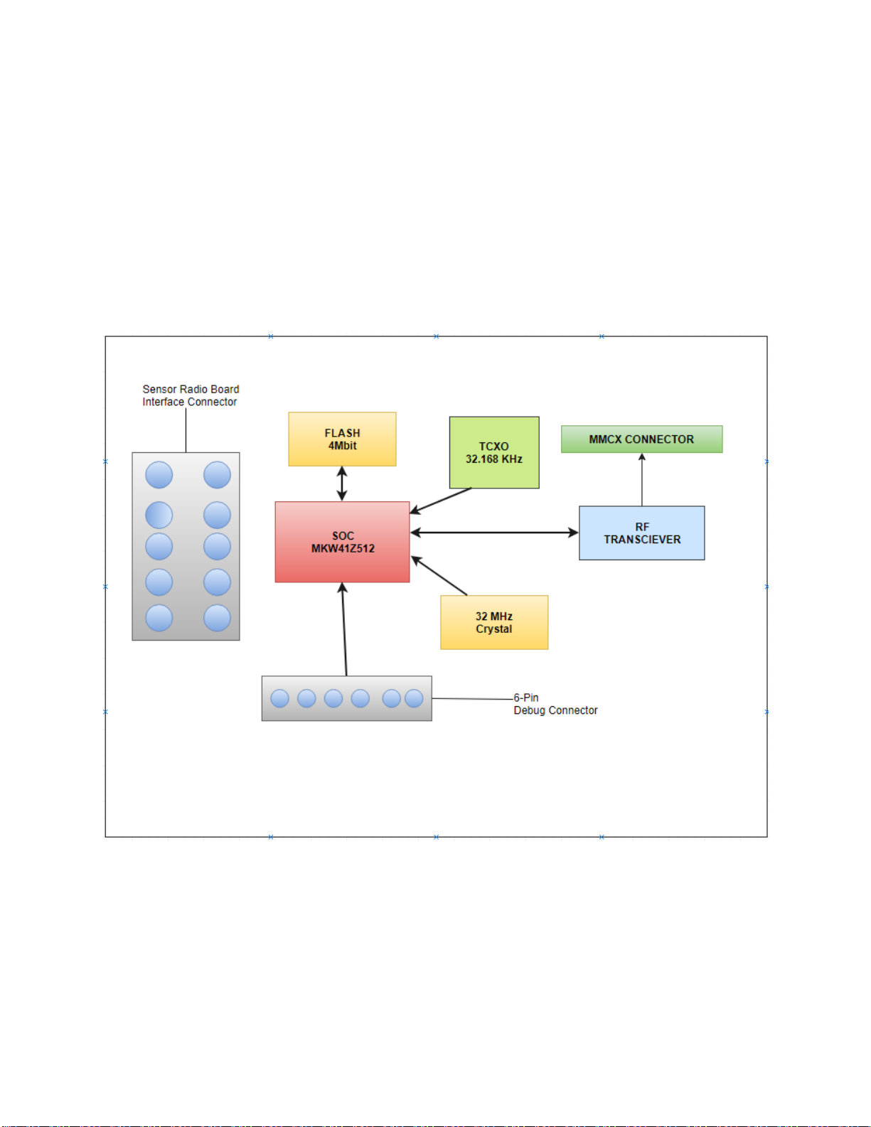
Figure 1: ISA100 Radio Board Block Diagram - Major Components ........................................ 10
Figure 2: Debug connector pin details ........................................................................................ 15
Figure 3: Connecting Debug Connector with J-Link Connector ................................................. 16
Figure 4: Debug Connector Pin Marking .................................................................................... 17
Figure 5: FET and Radio Board Connection ............................................................................... 18
Figure 6: Sensor-Radio Interface Connector ............................................................................... 20
Figure 7: ISA100 Device Architecture ........................................................................................ 23
Figure 8: SPI Communication Signals ........................................................................................ 25
Figure 9: Sensor-Radio Inter-Processor Interface ....................................................................... 28
Figure 10: Sensor Board Integration with RF Modem using ISA100/Full API .......................... 31
Figure 11: Sensor packets Logical Reference Model .................................................................. 32
Figure 12: Mechanical Drawing of ISA 100(1) .......................................................................... 59
Figure 13: Mechanical Drawing of ISA 100(2) .......................................................................... 60
Figure 14: J-Flash tool device selection ...................................................................................... 69
Figure 15: J-Flash tool data file selection ................................................................................... 70
Figure 16: J-Flash tool device programming…………………………. ...................................... 71
viii

Release Independent
April 2018
ISA100 Gen X Radio Module User's Guide
Honeywell
ix
ISA100 Gen X Radio Module User's Guide
Honeywell
Release Independent
April 2018
1 Introduction
1.1 Overview
ISA100 is a wireless protocol standard defined for industrial automation for Process Control and related
applications. The architecture of ISA100 is designed to be in coexistence with other wireless systems
conforming to this standard, in addition to other networks operating at 2.4 GHz such as ZigBee™,
WirelessHART™, 6LoWPAN, IEEE 802.11, Bluetooth™, and RFID systems. The Gen X ISA100 Radio
Hardware Module is 2.4GHz band, 802.15.4 Radio based hardware, and can host multiple software protocol
stacks like ISA100, zigbee™, 802.15.4, and WirelessHART™.
Figure 1: ISA100 Radio Board Block Diagram - Major Components
10

Release Independent
April 2018
ISA100 Gen X Radio Module User's Guide
Honeywell
REFERENCE - INTERNAL:
For Compliance Statements, refer to Appendix A: Compliance Statements
For Agency Label Information, refer to Appendix B: Agency Label
Information
11

ISA100 Gen X Radio Module User's Guide
Honeywell
Release Independent
April 2018
2 Specifications
2.1 Features
1. The operational frequency ranges from 2.4 GHz to 2.483 GHz.
2. The maximum number of channels allowed is 16.
3. The channel spacing must be 5 MHz ((2405, 2410,…..2475).
4. The transmitted power varies from -5 dBm to +20 dBm (adjusted as per antenna).
5. The type of modulation technique used is direct-sequence spread spectrum (DSSS).
6. The data rate is 250 kbps.
2.2 Electrical requirements
1. The operating voltage ranges from 2.7 Volts to 3.6 Volts.
2. The operating temperature ranges from -40 o C to +85 o C.
3. The electrical consumptions are:
Receive Mode (Rx): 19mA
Transmit Mode (Tx): 80mA @16 dBm
Average Sleep Mode: 30uA (When Radio is not transmitting and receiving)
2. 3 Types of Antenna
The Antenna Connector used in the module is MMCX-J-P-H-ST-TH1, which is a Jack throughhole connector and mates with all the MMCX Plug (preferred from Samtec). It is mandatory to
use a 50Ω connector towards the antenna for the described RF Power level performance.
The modular certification is performed for the antenna types (Refer to Table 1 Antenna Types).
The certification is void if you use any other antennas than the ones mentioned in the table.
12

Release Independent
April 2018
ISA100 Gen X Radio Module User's Guide
Honeywell
Table 1 Antenna Types
Sl.No
Antenna
Antenna gain
Power level settings
1
Centurion MAF94152 Omni
Antenna
-2
16
2
L-COM HG2402RDR-RSP
"Rubber-Duck"Omni Antenna
2
14
3
EM wave EM-B14503-MMPZ6
4
14
4
L-COM HGV-2404U Omni
Antenna
4
14
5
L-COM HGV-2409U Omni
Antenna
8
10
6
L-COM HG-2414D remote Dish
Antenna
14
6
13

ISA100 Gen X Radio Module User's Guide
Honeywell
Release Independent
April 2018
S No.
Power Level
1
20dBm
2
19dBm
3
18dBm
4
17dBm
5
15dBm
6
14dBm
7
12dBm
8
11dBm
9
10dBm
10
6dBm
11
4dBm
12
3dBm
13
1dBm
14
0dBm
15
-1dBm
16
-5dBm
2.4 Transmitter Power Configuration
Table 3 provides the transmit power output generated by the Radio at the input of the
antenna connector present on the Radio board.
Table 2 Transmit Power Settings
14

Release Independent
April 2018
ISA100 Gen X Radio Module User's Guide
Honeywell
3 Connector Details
There are two connectors on the Radio board:
1. Debug Connector for programming or to debug the firmware on the board
2. Sensor-Radio interface connector
3.1 Debug Connector Details
The debug connector is used for programming and/or debugging the firmware on the
board.
Debug Connector Pin Details
Figure 2: Debug connector pin details
SWS_DIO: data input/output
SWD_CLK: input clock
VCC: The operating voltage ranges from 2.7 Volts to 3.6 Volts.
15

ISA100 Gen X Radio Module User's Guide
Honeywell
Release Independent
April 2018
Connecting the Debug Connector to J-Link JTAG Connector
The following diagram explains the connection details of the Debug Connector to J-Link
JTAG Connector.
Figure 3: Connecting Debug Connector with J-LINK Connector
16

Release Independent
April 2018
ISA100 Gen X Radio Module User's Guide
Honeywell
Figure 4: Debug Connector Pin Marking
17

ISA100 Gen X Radio Module User's Guide
Honeywell
Release Independent
April 2018
Figure 5: FET and Radio Board Connection
18

Release Independent
April 2018
ISA100 Gen X Radio Module User's Guide
Honeywell
3.2 Sensor-Radio Interface Connector Details
The mating connector that connects the Radio interface is SFM-105-02-S-D-LC
Samtec.
MOSI, MISO, CS, and SCLK are used for SPI communication between the Radio and the
Sensor, whereas GPIO is used as General Purpose Input/output as well as interruptible
configurable pin.
Note: GPIO_02 pin in the Sensor-Radio interface connector is used as Sensor Data Ready
interrupts (SDR).GPIO_01 is the inverse of Chip Select(SPI_CS).
19

ISA100 Gen X Radio Module User's Guide
Honeywell
Release Independent
April 2018
20
Figure 6: Sensor-Radio Interface Connector

Release Independent
April 2018
ISA100 Gen X Radio Module User's Guide
Honeywell
1
GND
2
GND
3
GPIO_01(SPI_CS)
4
GPIO_02 (SDR)
5
SPI_CLK
6
SPI_MISO
7
SPI_MOSI
8
SPI_CS
9
VCC
10
VCC
The following table provides the Pin details of the Radio-Sensor interface connector.
Table 3 Pin Details of Radio Sensor Interface Connector
21

ISA100 Gen X Radio Module User's Guide
Honeywell
Release Independent
April 2018
4 Architectural Overview
The architecture of a device conforming to the ISA100 standards is described in terms of the
OSI basic reference model. As shown in Figure 7: ISA100 Device Architecture, each layer
provides a service access point (SAP). The services of a layer are defined as the functions and
capabilities of that layer that are exposed through the SAP to the surrounding layers. The
device manager is the entity within each device that performs the management function.
The ISA100 Gen X Radio Board implements the Device Manager (DMAP), ASLDE0 SAP,
and TDSAP-0 and all the other subsequent layers. The Sensor processor board implements the
User Application Process n (n = 2, 3, 4…15) and the equivalent ASLDE- n SAP and TDSAP-n.
The Sensor board usually contains one user application process. Within the user application
process, you can find one or more transducer blocks, one concentrator block to publish data to
the network, one upload download data object, and one user application process management
object. If the Sensor board implements only one user application process, then the n is usually 2.
The sensor user application process communicates locally to the DMAP present on the Radio
board using reserved local address methods. This includes a local contract id (0) for requests
and reserved destination addresses defined by the Null Address Pointer that is used for the
transfer of local data indications. Confirmation packets are referenced using a request handle
that originates from the requesting data object.
22
 Loading...