

Page 1

REVERSE OSMOSIS FILTRATION SYSTEM
69-2379EF—01
50045947-001
50045947-002
50045947-003
Safety Guides
Installation
Operation
Maintenance
Printed in U.S.A.
7312212 (Rev. B 9/25/09)
Page 2
2
TABLE OF CONTENTS
Specifications . . . . . . . . . . . . . . . . . . . . . . . . . . . 2
Dimensions . . . . . . . . . . . . . . . . . . . . . . . . . . . . . 2
Reverse Osmosis Filtration System . . . . . . . . . . 3
Parts Included . . . . . . . . . . . . . . . . . . . . . . . . . . . 3
Tools Needed . . . . . . . . . . . . . . . . . . . . . . . . . . . 3
Other Requirements . . . . . . . . . . . . . . . . . . . . . . 3
Safety Guidelines . . . . . . . . . . . . . . . . . . . . . . . . 3
RO System Assembly Installation. . . . . . . . . . . . 4
Plumbing . . . . . . . . . . . . . . . . . . . . . . . . . . . . . 5-7
RO System with Storage Tank. . . . . . . . . . . . . 5
RO System with Pump & Storage Tank. . . . . . 6
RO System. . . . . . . . . . . . . . . . . . . . . . . . . . . . 7
Operation . . . . . . . . . . . . . . . . . . . . . . . . . . . . . . 8
Maintenance . . . . . . . . . . . . . . . . . . . . . . . . . . . . 9
Troubleshooting . . . . . . . . . . . . . . . . . . . . . . . . 10
Maintenance Parts . . . . . . . . . . . . . . . . . . . . . . 11
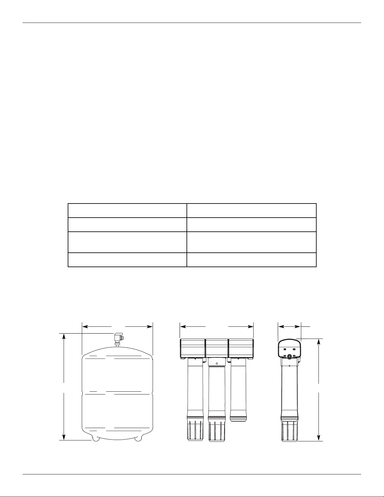
Specifications listed are based on average filter life of one year (one operating
season for the steam humidifier).
Water Hardness 0-25 grains per gallon (gpg)
Water Pressure 30-120 pounds per square inch (psi)
Water Temperature
40°F - 100°F
(only use on cold water supply)
Weight (RO System with water) 7 lbs.
DIMENSIONS
3-1/2”
16”
11-3/8”
11”
17”
SPECIFICATIONS
FIG. 1
Page 3

3
REVERSE OSMOSIS FILTRATION SYSTEM
This Reverse Osmosis (RO) filtration system
removes dissolved solids and organic matter from
water by passing it through a membrane which
separates and flushes minerals and impurities
from the water.
Install this system upstream of the steam humidifier’s water inlet. It is recommended that the RO
system’s filters be replaced at least once per year
to ensure optimal humidifier performance.
SAFETY GUIDELINES
Read, understand and follow all steps, guides
and requirements before installing the Reverse
Osmosis (RO) filtration system.
All water connections must comply with local
and state plumbing and sanitation codes.
Reference, understand and comply with all governing codes before installing the RO filtration
system.
Do not install on hot water supply. Only use
cold water supply.
Do not install outside or in unconditioned space
where there is potential for the water system to
freeze.
OTHER REQUIREMENTS
If the RO filtration system or the humidifier are installed in finished space or above ceilings, it is required
to install a water drip pan with a shutoff sensor under all water connections.
See steam humidifier manual, Appendix C.
TOOLS NEEDED
Crescent wrench
Philips screwdriver
PARTS INCLUDED
ALL MODELS
RO System Assembly
– RO manifold assembly
– Supply tubing (one 20 ft. long 1/4” dia.
white tube)
– Adapter elbow (3/8” x 1/4”)
– Drain line assembly (including one 6.5 ft.
long 1/4” dia. red tube, one 1 ft. long
1/4” dia. red tube, and drain flow restrictor assembled in drain line fitting)
– Mounting screws and washers
Water Filters
– #1 - Sediment filter
– #2 - Reverse osmosis filter
– #3 - Staging tank
SELECT MODELS (as listed)
Water Storage Tank
(Models 50045947-001 & 50045947-002)
– Storage tank
– Storage tank tubing (one 6 ft. long 3/8”
dia. yellow tube)
– Shutoff valve
– Teflon tape
Permeate Pump (Model 50045947-002)
– Permeate pump
– Mounting bracket and screws
– Tee fitting
Plug Fitting (Model 50045947-003)
Page 4
4
FIG. 2
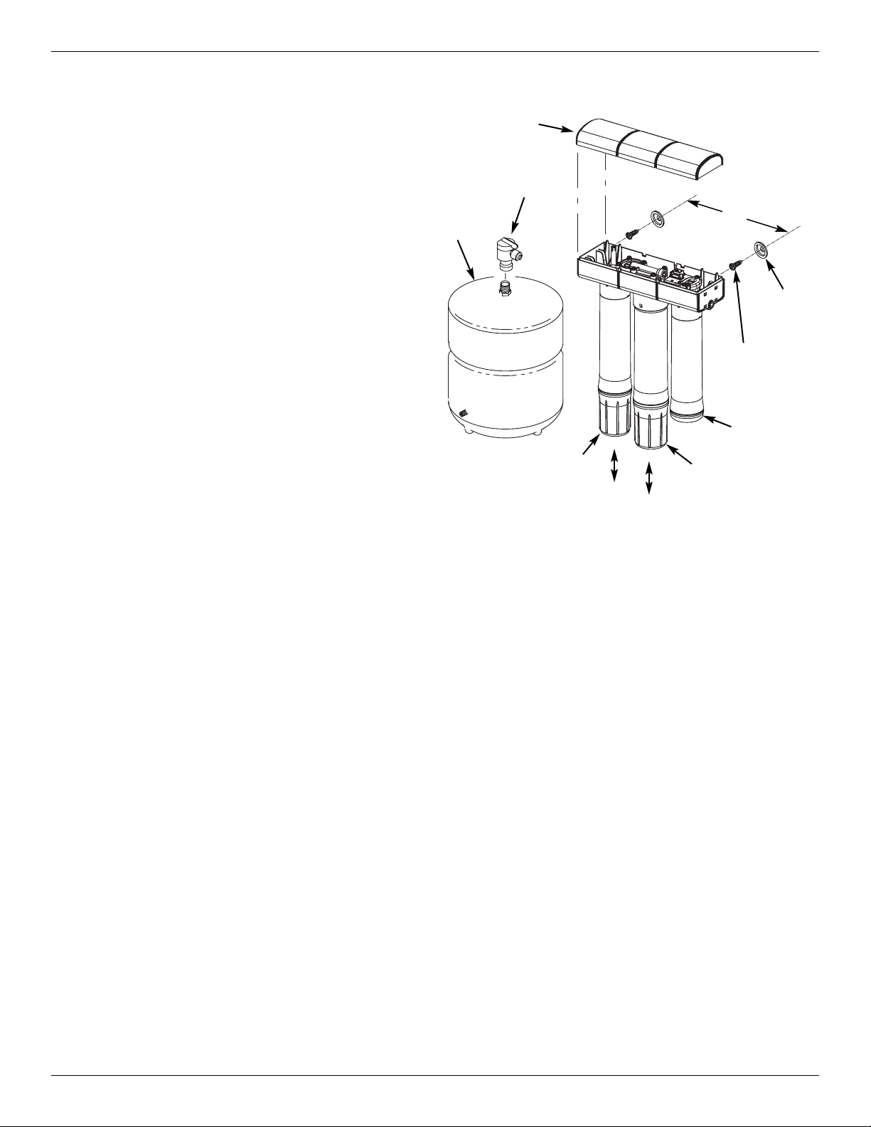
RO SYSTEM ASSEMBLY INSTALLATION
1. Choose a location for the RO system
assembly capable of holding up to 7 lbs.
2. Mark screw/washer location 9 inches apart.
3. Fasten screws and hanger washers.
– Sheet metal install – use sheet metal
screws (not provided).
– Wood stud install – use provided wood
screws and hanger washers.
4. Hang the RO system assembly on the
hanger washers.
5. Connect Filter Assembly top cover.
6. Connect three filter cartridges in the order
below by turning cartridge to the right,
ensuring thread is properly engaged and
seal is tight.
Align #3 staging tank with RO system
assembly connection #3.
Align #2 RO filter with RO system
assembly connection #2.
Align #1 sediment filter with RO system
assembly connection #1.
7. Move water storage tank into place on the
floor surface. Use the included tank stand
and position the tank upright or on its side
(Models 50045947-001 & 50045947-002).
8. Apply PTFE thread seal (Teflon) tape on
the storage tank thread and install the shutoff valve (Models 50045947-001 &
50045947-002).
9”
NOTE: Be sure to allow a minimum space
of 1-1/2" under the system for removing
and replacing the filters.
Shutoff
Valve
Storage
Tank
Hanger
Washer
(2)
Screw
(2)
Top Cover
#3
Staging Tank
#2
RO Filter
#1
Sediment Filter
(level)
Page 5
5
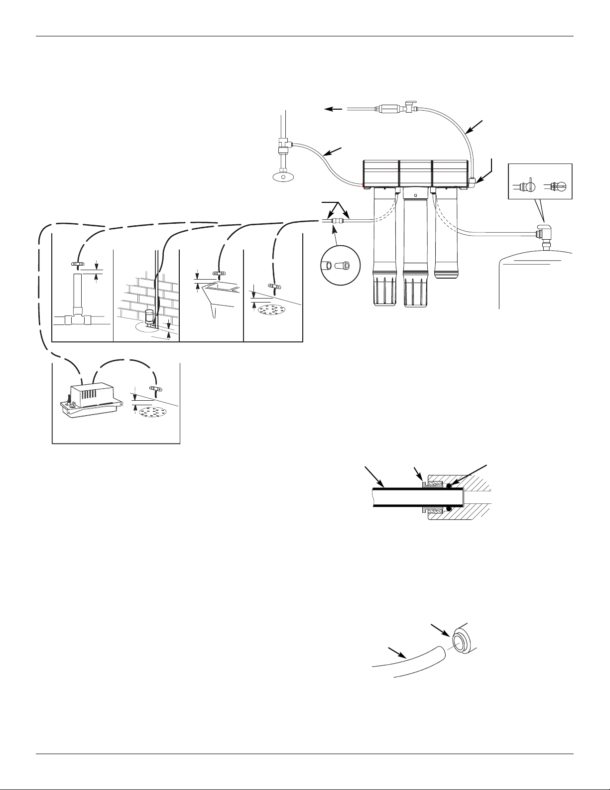
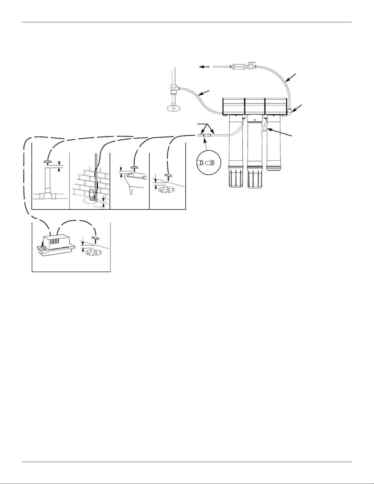
PLUMBING
Cut 1/4” dia. tubing lines to fit your installation.
Ensure all cuts are evenly made with no nicks,
scratches or rough spots on the tube end.
Longer tubing lengths – nylon or copper – may
also be used (not provided). Ends of tubing
must be round and free of burrs and scratches
to seal properly.
Install 3/8” x 1/4” adapter elbow into blue outlet
port.
Install 3/8” dia. yellow tube between yellow inlet
port and storage tank valve (Models 50045947001 & 50045947-002). Insert plug from parts
bag in yellow port for Model 50045947-003.
Locate drain line assembly (1/4” dia. red tubes
assembled to flow control coupling). Install 1 ft.
long end of 1/4” dia. red drain line into red port
in the RO system. Route the longer 1/4” dia.
red drain line to a drain. Note that the coupling
contains a flow control that is critical to the
function of the RO system. Make sure the
drain line assembly is installed correctly.
Push tubing completely into applicable fitting by
pushing past initial resistance and then applying
light pulling force to ensure a tight fit.
– To remove tube from connection, depress
collar and pull tubing.
FIG. 4
Water tube connections to the water supply, fil-
ter and steam humidifier must be checked for
leaks after installation and a short period of
operation.
Tube Fully Engaged with Fitting
Collar O-Ring
Tubing
Collar (depress to
remove tubing)
Tubing
FIG. 5
Storage Tank
Open
Closed
1/4” White
Tubing
3/8” x 1/4”
Adapter Elbow
Cold Water
Supply
1/4” White
Tubing
3/8”
Yellow Tubing
Drain Flow
Control
Drain Points for Reject Water
Follow local codes for proper installation
Refer to additional drain requirements in steam
humidifier manual when coupling RO drain and
humidifier drain
Standpipe
Sump
Laundry
Tub
Floor
Drain
air gap
air
gap
air
gap
air
gap
RO System with
Storage Tank
(Model 50045947-001)
#1 #2 #3
To Steam
Humidifier
Shutoff
Control Valve
1/4”
Red Tubing
Floor
Drain
Condensate
Pump
air
gap
FIG. 3
Page 6
6
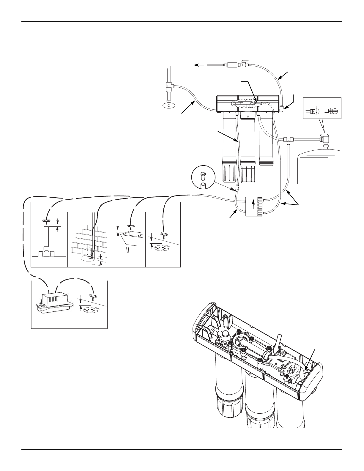
PLUMBING (continued)
FIG. 7
Connect
1/4” White
Tubing
Route tube
through hole
Install water pump (labeled permeate pump)
with mounting bracket and screws. Make sure
pump is level and is oriented with arrow pointing up.
Remove top cover of RO system and connect a
1/4” tube to the auto shutoff assembly. Route
the tube through the hole provided and to the
permeate inlet on the pump. Snap top cover
back on RO system.
1/4” White
Tubing
3/8”
Yellow Tubing
1/4”
Red Tubing
Drain Flow
Control
Standpipe
Sump
Laundry
Tub
Floor
Drain
air gap
air
gap
air
gap
air
gap
#1 #2 #3
1/4”
Red Tubing
1/4” White
Tubing
brine
out
permeate
out
brineinpermeate
in
Water
Pump
(must be installed with
arrow pointing up)
1/4” White
Tubing
Connect
1/4” White
Tubing
UP
RO System with
Water Pump &
Storage Tank
(Model 50045947-002)
Drain Points for Reject Water
Follow local codes for proper installation
Refer to additional drain requirements in steam
humidifier manual when coupling RO drain and
humidifier drain
1/4” White
Tubing
3/8” x 1/4”
Adapter Elbow
Storage Tank
Open
Closed
Floor
Drain
Condensate
Pump
air
gap
Cold Water
Supply
To Steam
Humidifier
Shutoff
Control Valve
FIG. 6
Page 7
7
PLUMBING (continued)
Floor
Drain
Condensate
Pump
air
gap
Plug Fitting
(insert into
yellow port)
1/4”
Red Tubing
Drain Flow
Control
Standpipe
Sump
Laundry
Tub
Floor
Drain
air gap
air
gap
air
gap
air
gap
#1 #2 #3
RO System
(Model 50045947-003)
Drain Points for Reject Water
Follow local codes for proper installation
Refer to additional drain requirements in steam
humidifier manual when coupling RO drain and
humidifier drain
1/4” White
Tubing
3/8” x 1/4”
Adapter Elbow
Cold Water
Supply
1/4” White
Tubing
To Steam
Humidifier
Shutoff
Control Valve
FIG. 8
Page 8

8
OPERATION
RO System Assembly
The RO System Assembly directs the flow of
water into the filters in numeric order, and out to
the steam humidifier. A built-in backflow prevention valve prevents the backward flow of water
from the storage tank. The shutoff/check valve
provided with the steam humidifier must still be
installed between the RO system and the steam
humidifier.
#1 Sediment Filter
Cold water enters the sediment filter, reducing
chlorine, sand, silt, dirt and other sediment. This
filters the feed water before entering the RO filter.
#2 Reverse Osmosis (RO) Cartridge
Filtered water enters the RO filter where dissolved minerals are removed, effectively ‘softening’ the hardness of the water. This reduces the
amount of solid mineral (scale/sediment) fallout
inside the steam humidifier’s tank. Reducing the
amount of scale and sediment increases the time
between manual cleanings of the steam humidifier.
#3 Staging Tank Canister
After leaving the storage tank, but before going to
the steam humidifier, water enters the #3 staging
tank canister. This canister holds the initial water
that enters steam humidifier when the solenoid fill
valve opens.
Storage Tank
The storage tank holds filtered water. A
diaphragm inside the tank keeps water pressurized when the tank is full, to provide fast flow
from the RO outlet. The tank is charged with 5-7
psi air. The automatic shutoff valve fills and pressurizes the tank when low, and stops the flow of
water when the tank is full.
NOTE: It is normal to hear the RO System oper-
ating the first few days after the initial
installation. This will dissipate as air is
purged from the system.
Page 9

9
MAINTENANCE
Replacement Steps - Water Filters
It is recommended that the #1 sediment filter
and #2 RO filter be replaced at least once per
season or as needed.
Do not replace the #3 staging tank. At the end
of the humidification season, unscrew the #3 filter and empty any remaining water.
When installing new filters, install #2 RO filter
first, followed by the #1 sediment filter.
End-of-Season Steps
Empty the Storage Tank
1. Close the storage tank shutoff valve.
2. Disconnect the yellow tubing from the RO
system assembly. Route the disconnected
end to a drain outlet.
3. Open the storage tank shutoff valve.
4. When water stops draining from the yellow
tube, the tank is empty.
5. Close the storage tank shutoff valve.
6. Reconnect the yellow tube to the RO sys-
tem assembly.
7. When ready to humidify again, open the
storage tank shutoff valve.
Flow Control
1. Disconnect the red tube at the connector
that is in the drain line approx. 12” from RO
assembly, leaving the connector attached
to the RO system.
2. Remove and replace the cylindrical plastic
flow control that is inserted in the end of the
red tube removed from the connector. If
the plastic flow control does not appear to
be in the end of the red tubing, it may have
stayed in the connector when the tube was
removed. Remove the old flow control from
the connector before installing the new one
in the end of the tubing.
Replace
FIG. 9
Turn cartridges in the direction of
the arrow to remove. Turn them
in the opposite direction to install.
#3
Staging Tank
#2
RO Filter
#1
Sediment Filter
Replace
Remove,
empty and
reconnect
NOTE: Refer to the steam humidifer’s manual for
more detailed maintenance steps.
Page 10

10
TROUBLESHOOTING
Number of
“Service” red
light blinks
Description Possible Cause Corrective Action
2 Water level sensors
failed to detect tank
water
Scaling on the sensor Replace #1 sediment filter and
#2 RO filter. See steam
humidifier manual troubleshooting section for specific
humidifier steps
3 Failed to fill steam
humidifier tank
Expired #1 and #2 water filters
Missing flow control in drain
line
Replace flow control (provided
with 50046086-001)
Storage tank air charge is
less than 5-7 psi (Models
50045947-001 &
50045947-002
Drain the storage tank. Check
tank air pressure and, if low,
pressurize to 6 psi
4 Heating element
overheated
Scaling on element See steam humidifier manual
for cleaning steps
6 Water overflow
sensed in tank
Heavy sediment in tank
13 Tank failed to drain
Blinking “Cleaning
required” light on
steam humidifier
Continual water flow
to drain
Check valve or automatic
shutoff assembly plugged or
parts worn
Replace RO system
The following table refers to the steam humidifier’s fault detection feature.
Page 11

11
MAINTENANCE PARTS
Key
No.
Part Number Description
1
50046083-001 One #1 sediment filter
2
50046084-001 One #2 reverse osmosis (RO) filter
3
50046089-001 One #3 staging tank
4
50046086-001
Filter kit, including one #1 sediment filter,
one #2 RO filter, and one flow control
4
3
21
FIG. 10
Page 12

12
Page 13

SYSTÈME DE FILTRES À OSMOSE INVERSE
69-2379EF—01
50045947-001
50045947-002
50045947-003
Consignes de sécurité
Installation
Utilisation
Entretien
Imprimé aux États-Unis
7312212 (Rév. B 9/25/09)
13
Page 14

14
TABLE DES MATIÈRES
Spécifications . . . . . . . . . . . . . . . . . . . . . . . . . . 14
Dimensions . . . . . . . . . . . . . . . . . . . . . . . . . . . . 14
Système de filtres à osmose inverse . . . . . . . . 15
Pièces incluses . . . . . . . . . . . . . . . . . . . . . . . . . 15
Outils nécessaires. . . . . . . . . . . . . . . . . . . . . . . 15
Autres impératifs . . . . . . . . . . . . . . . . . . . . . . . . 15
Consignes de sécurité . . . . . . . . . . . . . . . . . . . 15
Installation de l’assemblage du système
à osmose inverse . . . . . . . . . . . . . . . . . . . . . . . 16
Plomberie. . . . . . . . . . . . . . . . . . . . . . . . . . . 17-19
Système à osmose inverse avec
réservoir de stockage . . . . . . . . . . . . . . . . . . 17
Système à osmose inverse avec
pompe et réservoir de stockage . . . . . . . . . . 18
Système à osmose inverse . . . . . . . . . . . . . . 19
Utilisation . . . . . . . . . . . . . . . . . . . . . . . . . . . . . 20
Entretien . . . . . . . . . . . . . . . . . . . . . . . . . . . . . . 21
Dépannage . . . . . . . . . . . . . . . . . . . . . . . . . . . . 22
Pièces d’entretien . . . . . . . . . . . . . . . . . . . . . . . 23
Les spécifications suivantes ont été calculées en fonction de la durée de vie
moyenne d’un filtre d’un an (une saison pour l’humidificateur à vapeur).
Dureté de l’eau 0-428 ppm (0-25 gpg)
Pression de l’eau 207 à 827 kPa (30-120 psi)
Température de l’eau
4 °C à 38 °C (40 °F à 100 °F)
(eau froide uniquement)
Poids (Système d’osmose
inverse et eau)
3,2 kg (7 lb)
DIMENSIONS
9 cm (3-1/2 po)
40,6 cm
(16 po)
29 cm (11-3/8 po)
SPÉCIFICATIONS
FIG. 11
28 cm (11 po)
43 cm
(17 po)
Page 15

15
SYSTÈME DE FILTRES À OSMOSE INVERSE
Le système de filtrage à osmose inverse retire les
matières solides et organiques dissoutes de l’eau
en les faisant traverser une membrane séparant
et évacuant les minéraux et impuretés de l’eau.
Installez ce système à contre-courant de l’entrée
d’eau de l’humidificateur à vapeur. Il est recommandé de remplacer le filtre du système à
osmose inverse au moins une fois par an pour
optimiser les performances de l’humidificateur.
CONSIGNES DE SÉCURITÉ
Lisez, comprenez et respectez toutes les étapes,
consignes et conditions requises avant d’installer
le système de filtres à osmose inverse.
Tous les raccords d’eau doivent être conformes
aux codes de plomberie et sanitaires locaux et
régionaux. Comprenez et conformez-vous à
toutes les réglementations en vigueur avant d’installer le système de filtres à osmose inverse.
Ne l’installez pas sur la conduite d’eau chaude.
N’utilisez qu’une conduite d’eau froide.
Ne l’installez pas à l’extérieur ou dans un espace
non conditionné où le système est susceptible
de geler.
AUTRES IMPÉRATIFS
Si le système à osmose inverse ou l’humidificateur est installé en espace fini ou au plafond, il est
nécessaire d’installer un bac d’égouttage de l’eau avec robinet d’arrêt sous tous les raccords d’eau.
Consultez le manuel de l’humidificateur à vapeur, annexe C.
OUTILS NÉCESSAIRES
Clé anglaise
Tournevis cruciforme
PIÈCES INCLUSES
TOUT MODÈLE
Assemblage du système à
osmose inverse
– Ensemble collecteur à osmose inverse
– Tuyau d’alimentation (1 tuyau blanc,
longueur : 6,1 m/20 pieds,
diamètre : 0,65 cm/1/4 po)
– Adaptateur (coude), 0,95 cm x 0,65 cm
(3/8 po x 1/4 po)
– Ensemble de conduites d’évacuation
(tuyau rouge, longueur : 198 cm/6,5 pieds,
diamètre : 0,65 cm/1/4 po ; tuyau rouge,
longueur 30,5 cm/1 pied, diamètre :
0,65 cm/1/4 po ; restricteur assemblé
au raccord de vidange)
– Vis et rondelles de montage
Filtres d’eau
– n°1 - Filtre à sédiment
– n°2 - Filtre à osmose inverse
– n°3 - Réservoir à étapes
MODÈLES SÉLECTIONNÉS (sur liste)
Réservoir d’eau
(Modèles 50045947-001 et 50045947-002)
– Réservoir de stockage
– Tuyau du réservoir de stockage (1 tuyau
jaune, longueur : 183 cm/6 pieds,
diamètre : 0,95 cm/3/8 po)
– Robinet d’arrêt
– Ruban en téflon
Pompe perméat (modèle 50045947-002)
– Pompe perméat
– Vis et bracelet de fixation
– Raccord en T
Raccord électrique (modèle 50045947-003)
Page 16

16
FIG. 12
INSTALLATION DE L’ENSEMBLE DU
SYSTÈME À OSMOSE INVERSE
1. Choisissez un espace où l’ensemble du
système à osmose inverse est en mesure
de supporter jusqu’à 3,2 kg (7 lb).
2. Marquez l’emplacement des vis et des ron-
delles à 23 cm (9 po) d’intervalle.
3. Vissez les vis et rondelles étriers.
– Pour une installation sur tôle, utilisez
des vis appropriées (non fournies)
– Pour une installation sur colombage
de bois, utilisez des vis à bois et des
rondelles étriers.
4. Posez l’ensemble du système à osmose
inverse sur les rondelles étriers.
5. Placez le couvercle de l’ensemble du filtre.
6. Placez trois cartouches de filtre dans l’or-
dre suivant en tournant la cartouche vers la
droite, en s’assurant que le fil est bien
engagé et que le joint est bien serré.
Alignez le réservoir à étapes n° 3 avec
l’assemblage du système à osmose
inverse, raccord n° 3.
Alignez le filtre à osmose inverse
n° 2 avec l’assemblage du système à
osmose inverse, raccord n° 2.
Alignez le filtre à sédiment n°1
avec l'assemblage du système
à osmoseinverse, raccord n°1.
7. Posez le réservoir d’eau en place à
la surface du sol. Utilisez le socle du réservoir inclus et positionnez le réservoir
à la verticale ou allongé sur le côté (modèles 50045947-001 et 50045947-002).
8. Appliquez le ruban (Téflon) joint pour fil
PTFE sur le fil du réservoir de stockage
et installez le robinet d’arrêt (modèles
50045947-001 et 50045947-002).
23 cm
(9 po)
REMARQUE : Prévoyez un espace
minimum de 4 cm (1 ½ po) sous le
système pour déposer et remplacer
les filtres.
Robinet
d’arrêt
Réservoir
de stockage
Rondelle
de support
(2)
Vis (2)
Couvercle
supérieur
n°3
Réservoir
à étapes
n°2
Filtre à osmose inverse
n°1
Filtre à sédiments
(niveau)
Page 17

17
PLOMBERIE
Découpez des tuyaux de 0,65 cm (1/4 po) de diamètre
pour installer votre montage. Vérifiez que toutes les
découpes sont uniformes et ne présentent aucune
éraflure, entaille ou rugosité à l’extrémité du tuyau.
Il est également possible d’utiliser des tuyaux plus
longs, en nylon ou cuivre (fournis). Les extrémités des
tuyaux ne doivent présenter aucune éraflure ni rugosité
pour un raccordement correct.
Installez l’adaptateur coude 0,95 x 0,65 cm
(3/8 x 1/4 po) sur le port de sortie bleu.
Installez le tuyau jaune de 0,65 cm (3/8 po) de
diamètre entre le port d’entrée jaune et le robinet du
réservoir de stockage (modèles 50045947-001 et
50045947-002). Branchez la prise (que vous trouverez
dans le sachet des pièces) au port jaune du modèle
50045947-003.
Localisez l’assemblage du tuyau de vidange (tuyaux
rouges 0,65 cm (1/4 po) assemblés au couplage de
contrôle de débit). Installez le tuyau de vidange rouge
de 30,5 cm (1 pied) et de 0,65 cm (1/4 po) de diamètre
dans le port rouge du système à osmose inverse.
Raccordez le tuyau de vidange rouge de 0,65 cm
(1/4 po) de diamètre à un drain. Notez que le couplage
comprend un contrôle de débit crucial pour le fonctionnement du système à osmose inverse.
Vérifiez l’installation correcte de l’assemblage du tuyau
de vidange.
Poussez le tuyau sur toute sa longueur dans le raccord
applicable en dépassant sa résistance initiale, puis en
appliquant une légère force de poussée pour assurer
le serrage.
FIG. 13
– Pour déconnecter le tuyau, enfoncez le col et tirez
le tuyau.
FIG. 14
Réservoir
de stockage
Ouvert
Fermé
Tuyau blanc
de 0,65 cm (1/4 po)
de diamètre
Adaptateur (coude),
0,95 cm x 0,65 cm
(3/8 po x 1/4 po)
Alimentation
en eau froide
Tuyau blanc
de 0,65 cm (1/4 po)
de diamètre
Tuyau jaune
de 0,95 cm (3/8 po)
de diamètre
Régulateur
de débit d’é-
vacuation
Points d’évacuation des eaux usées
Respectez les réglementations locales pour
disposer d’une installation dans les normes.
Consultez les conditions d’évacuation supplémen-
taires du manuel de l’humidificateur à vapeur avant
couplage du tuyau de vidange à osmose inverse et
vidange de l’humidificateur.
Conduite
verticale
Puisard
Cuve
de lessivage
Drain
de sol
Système à osmose
inverse avec réservoir
de stockage
(Modèle 50045947-001)
n°1 n°2 n°3
Les branchements entre pompes à eau et alimentation
en eau, le filtre et l’humidificateur à vapeur doivent être
vérifiés pour garantir l’absence de fuites après installation et après une courte période d’utilisation.
Tube totalement inséré dans le raccord
Col Joint torique
Tuyau
Vers l’humidifi-
cateur à vapeur
Robinet de com-
mande d’arrêt
Tuyau rouge de
0,65 cm (1/4 po)
de diamètre
Drain
de sol
Pompe à eau
de condensation
Espace
d’air
Espace
d’air
Espace
d’air
Espace
d’air
Espace d’air
Tuyau
Col (doit être enfoncé pour
pouvoir retirer le tuyau)
FIG. 15
Page 18

18
PLOMBERIE (suite)
FIG. 16
Tuyau blanc de 0,65 cm
(1/4 po) de diamètre
Tuyau jaune de
0,95 cm (3/8 po)
de diamètre
Tuyau rouge
de 0,65 cm (1/4 po)
de diamètre
Régulateur de
débit d’évacuation
Puisard
Cuve
de lessivage
Drain
de sol
n°1 n°2 n°3
Tuyau rouge de
0,65 cm (1/4 po)
de diamètre
Tuyau blanc
de 0,65 cm (1/4 po)
de diamètre
Sortie
saumure
Sortie
perméat
Entrée
saumure
Entrée
perméat
Pompe à eau
(installez avec la flèche
vers le haut)
Tuyau blanc
de 0,65 cm (1/4 po)
de diamètre
Tuyau blanc
de 0,65 cm (1/4 po)
de diamètre de raccord
FIG. 17
Tuyau blanc
de 0,65 cm (1/4 po)
de raccord
Faites passer le
tuyau dans le trou
Installez la pompe à eau (appelée pompe per-
méat) à l’aide des bracelets de montage et des
vis. Vérifiez que la pompe est au bon niveau et
orientez la flèche vers le haut.
Retirez le couvercle supérieur du système
à osmose inverse et raccordez un tuyau
de 0,65 cm (1/4 po) à l’assemblage d’arrêt
automatique. Faites passer le tuyau par le
trou fourni vers l’entrée de perméat de la
pompe. Refermez le couvercle du système
à osmose inverse.
HAUT
Système d’osmose
inverse avec pompe
à eau et réservoir
de stockage
(Modèle 50045947-002)
Points d’évacuation des eaux usées
Respectez les réglementations locales pour une
installation dans les normes.
Consultez les conditions d’évacuation supplé-
mentaires dans le manuel de l’humidificateur à
vapeur avant de coupler le tuyau de vidange à
osmose inverse et la vidange de l’humidificateur.
Tuyau blanc de
0,65 cm (1/4 po)
de diamètre
Adaptateur (coude),
0,95 cm x 0,65 cm
(3/8 po x 1/4 po)
Réservoir
de stockage
Ouvert
Fermé
Drain
de sol
Pompe à eau
de condensation
Espace
d’air
Espace
d’air
Espace
d’air
Espace
d’air
Espace d’air
Conduite
verticale
Alimentation
en eau froide
Vers l’humidifi-
cateur à vapeur
Robinet de com-
mande d’arrêt
Page 19

19
PLOMBERIE (suite)
FIG. 18
Raccord électrique
(à insérer dans le
port jaune)
Régulateur
de débit d’é-
vacuation
Puisard
Cuve
de lessivage
Drain
de sol
n°1 n°2 n°3
Système à
osmose inverse
(Modèle 50045947-003)
Points d’évacuation des eaux usées
Respectez les réglementations locales pour une
installation dans les normes
Consultez les conditions d’évacuation supplémen-
taires dans le manuel de l’humidificateur à vapeur
avant de coupler le tuyau de vidange à osmose
inverse et la vidange de l’humidificateur
Tuyau blanc
de 0,65 cm (1/4 po)
de diamètre
Adaptateur (coude),
0,95 cm x 0,65 cm
(3/8 po x 1/4 po)
de diamètre
Drain
de sol
Pompe à eau
de condensation
Espace
d’air
Espace
d’air
Espace
d’air
Espace d’air
Conduite
verticale
Espace
d’air
Alimentation
en eau froide
Vers l’humidifi-
cateur à vapeur
Robinet de com-
mande d’arrêt
Tuyau rouge de
0,65 cm (1/4 po)
de diamètre
Tuyau blanc
de 0,65 cm (1/4 po)
de diamètre
Page 20

20
UTILISATION
Assemblage du système à osmose inverse
L’assemblage du système à osmose inverse
dirige le débit d’eau dans les filtres dans un ordre
numérique, puis vers l’humidificateur à vapeur.
Un clapet antiretour intégré empêche le retour
de l’eau depuis le réservoir de stockage.
Le robinet d’arrêt/clapet de retenue fourni avec
l’humidificateur à vapeur doit toujours être installé
entre le système à osmose inverse et
l’humidificateur à vapeur.
N° 1 Filtre à sédiments
L’eau froide pénètre dans le filtre à sédiments,
pour réduire la présence de chlore, de sable,
de limon, d’impuretés et d’autres sédiments.
Il filtre l’eau d’alimentation avant qu’elle n’atteigne
le filtre d’osmose inverse.
N° 2 Cartouche d’osmose inverse
L’eau filtrée pénètre dans le filtre à osmose
inverse où sont retirés les minéraux dissous,
ce qui adoucit efficacement la dureté de l’eau.
Cela réduit la quantité de minéraux solides (sédiments/tartre) à l’intérieur du réservoir
de l’humidificateur à vapeur. Le fait de réduire
la quantité de tartre et de sédiments permet d’espacer les nettoyages manuels
de l’humidificateur à vapeur.
N° 3 Canister du réservoir à étapes
Après être sortie du réservoir de stockage, avant
d’entrer dans l’humidificateur à vapeur, l’eau entre
dans le canister du réservoir à étapes n° 3.
Ce canister maintient l’eau d’origine entrant dans
l’humidificateur à vapeur lorsque s’ouvre l’électrovanne commandée de remplissage (EVR).
Réservoir de stockage
Le réservoir de stockage emmagasine l’eau filtrée. Le réservoir contient un diaphragme
intérieur pour maintenir la pression de l’eau
quand il est plein afin d’assurer un écoulement
rapide depuis la sortie osmose inverse.
Le réservoir est rempli d’air 35 à 48 kPa (5 à
7 psi). Le robinet d’arrêt automatique sert à remplir et à pressuriser le réservoir si le niveau est
trop bas, et à interrompre le courant d’eau si le
réservoir est plein.
REMARQUE : Il est normal d’entendre un bruit
du système à osmose inverse qui
fonctionne pendant plusieurs jours
après l’installation initiale. Ce bruit
s’atténue grâce à l’air purgé du
système.
Page 21

21
ENTRETIEN
Étapes de remplacement : filtres à eau
Il est recommandé de remplacer le filtre à sédiments
n° 1 et le filtre à osmose inverse n° 2 au moins une
fois par saison ou plus tôt si nécessaire.
Ne remplacez pas le réservoir à étapes n° 3. À la fin
de la saison d’humidification, dévissez le filtre n° 3
et videz l’eau restante.
Lors de l’installation de nouveaux filtres, installez
un filtre à osmose inverse n° 2 avant le filtre à sédiments n° 1.
Étapes de fin de saison
Vidage du réservoir de stockage
1. Fermez le robinet d’arrêt du réservoir
de stockage.
2. Débranchez le tuyau jaune de l’assemblage
du système à osmose inverse. Faites passer
l’extrémité déconnectée par une sortie d’évacuation.
3. Ouvrez le robinet d’arrêt du réservoir
de stockage.
4. Quand l’eau cesse de s’écouler du tuyau jaune,
le réservoir est vide.
5. Fermez le robinet d’arrêt du réservoir
de stockage.
6. Rebranchez le tuyau jaune à l’assemblage du
système à osmose inverse.
7. Lorsque vous êtes prêt à lancer l’humidification,
ouvrez le robinet d’arrêt du réservoir.
Régulateur de débit
1. Débranchez le tuyau rouge du connecteur du
tuyau d’évacuation à environ 30,5 cm (12 po)
de l’ensemble du système à osmose inverse
en laissant le connecteur raccordé au système
à osmose inverse.
2. Retirez et remplacez le cylindre plastique
de contrôle de débit inséré à l’extrémité du
tuyau rouge retiré du connecteur. Si le contrôle
de débit plastique est absent de l’extrémité
du tuyau rouge, il se peut qu’il soit resté sur le
connecteur après que le tuyau a été retiré.
Retirez l’ancien contrôle de débit du connecteur
avant d’installer le nouveau à l’extrémité
du tuyau.
Remplacez
FIG. 19
Faites tourner les cartouches
dans la direction indiquée par les
flèches pour les retirer. Faites-les
tourner dans la direction inverse
pour les installer.
Réservoir à
étapes n° 3
Filtre à osmose
inverse n° 2
Filtre à sédi-
ments n° 1
Remplacez
Retirez,
videz et
rebranchez
REMARQUE : Consultez le manuel de l’humidifica-
teur à vapeur pour plus de renseignements sur les étapes d’entretien.
Page 22

22
DÉPANNAGE
Nombre de
clignotements
du voyant
rouge de
« Service »
Description Cause possible Mesure corrective
2 Les capteurs du
niveau d’eau n’ont
pas détecté l’eau
du réservoir
Tartre sur capteur Remplacez le filtre à sédi-
ments n° 1 et le filtre d’osmose inverse n° 2. Consultez
la section relative au dépannage dans le manuel de l’humidificateur à vapeur pour
connaître les étapes spécifiques de l’humidificateur
3 Le réservoir
de l’humidificateur
à vapeur n’a pas
été rempli
Filtres n° 1 et 2 périmés
Contrôle de débit du tuyau
de vidange absent
Remplacez le contrôle de
débit (fourni avec le modèle
50046086-001)
Charge d’air du réservoir
de stockage inférieure à
35-48 kPa (5-7 psi) (modèles 50045947-001 et
50045947-002
Videz le réservoir de stockage.
Vérifiez la pression de l’air du
réservoir et pressurisez à
41 kPa (6 psi) si la pression
est trop basse
4 Surchauffe
de l’élément
de chauffage
Tartre sur l’élément Consultez le manuel de l’hu-
midificateur à vapeur pour
connaître les étapes de nettoyage
6 Débordement
d’eau détecté
dans le réservoir
Excès de sédiments dans
le réservoir
13 Le réservoir ne s’est
pas vidé
Clignotement
du voyant « Cleaning
required » (nettoyage
nécessaire)
de l’humidificateur
à vapeur
Débit d’eau continuel vers drainage
Clapet de retenue ou
ensemble d’arrêt automatique branché ou pièces
usées
Remplacez le système
à osmose inverse
Le tableau suivant se rapporte à la fonction de détection d’erreurs de l’humidificateur à vapeur.
Page 23

23
PIÈCES D’ENTRETIEN
N° de
repère
Numéro de
pièce
Description
1
50046083-001 1 filtre à sédiments n° 1
2
50046084-001 1 filtre d’osmose inverse n° 2
3
50046089-001 1 réservoir à étapes n° 3
4
50046086-001
Kit de filtration, avec un filtre de sédiments n° 1, un filtre d’osmose inverse
n° 2 et un contrôle de débit
4
3
21
FIG. 20
Page 24

24
 Loading...