

Honeywell 50025034 Users Guide

OneWireless
XYR 6000 Wireless Valve Position Sensor
Model: WCX Series
Quick Start Guide
50040850
Revision 1
1/20/09

Notices and Trademarks
Copyright 2009 by Honeywell International Inc.
Revision 1 January 20, 2009
While this information is presented in good faith and believed to be accurate, Honeywell disclaims the implie d
warranties of merchantability and fitness for a particular purpose and makes no express warranties except as may
be stated in its written agreement with and for its customers.
In no event is Honeywell liable to anyone for any indirect, special or consequential damages. The information and
specifications in this document are subject to change without notice.
Honeywell, PlantScape, Experion PKS, and TotalPlant are registered trademarks of Honeywell International Inc.
Other brand or product names are trademarks of their respective owners.
Automation and Control Solutions
Sensing and Control
Honeywell
1985 Douglas Drive North
Minneapolis, MN 55422
www.honeywell.com/sensing
ii OneWireless XYR 6000 Wireless Valve Position Sensor Quick Start Guide Revision 1
1/15/09

About This Document
This document describes mounting, installation and wiring of the WCX Series Valve Position Sensor and antennas.
Configuration, authentication and ope rat i on are c overed in other documents.
Honeywell does not recommend using devices for critical control where there is a single point of failure or where
single points of failure result in unsafe conditions. OneWireless is targeted at open loop control, supervisory
control, and controls that do not have environmental or safety consequences. As with any process control solution,
the end-user must weigh the risks and benefits to determine if the products used are the right match for the
application based on security, safety, and perfo rmance. Additionally, it is up to the end-user to ensure that the
control strategy sheds to a safe operating condition if any crucial segment of the control solu tion fails.
Revision Information
Document Name Document ID
Revision
Number
Publication
Date
XYR 6000 Wireless Valve Position Sensor,
Model WCX Series Quick Start Guide
50040850 1 1/20/09
References
The following list identifies all documents that may be sources of reference for material discussed in this
publication.
Document Title
Getting Started with Honeywell OneWireless Solutions
OneWireless Wireless Builder User’s Guide
OneWireless Builder Parameter Reference
OneWireless XYR 6000 Wireless Valve Position Sensor, Model WCX Series User's Manual
OneWireless XYR 6000 Pressure Transmitter User's Manual
OneWireless XYR 6000 Temperature/DI Transmitter User's Manual
OneWireless XYR 6000 SmartCET Corrosion Transmitter User's Manual
OneWireless XYR 6000 HLAI Transmitter User's Manual
Revision 1 OneWireless XYR 6000 Wireless Valve Position Sensor Quick Start Guide iii
1/20/09

Support and contact info
WARNING
Risk of death or serious injury from explosion or fire.
If sensor is to be returned to Honeywell for any reason, both batteries MUST
be removed prior to shipping. Dispose of used batteries promptly per local
regulations or the battery manufacturer’s recommendations. Keep away from
children. Do not disassemble and do not dispose of in fire.
Sales and Service
Honeywell serves its customers through a worldwide network of sales offices, representatives and
distributors. For application assistance, current specifications, pricing or name of the nearest Authorized
Distributor, contact your local sales office or:
E-mail: info.sc@honeywell.com
Internet: www.honeywell.com/sensing
Phone and Fax:
Asia Pacific +65 6355-2828
+65 6445-3033 Fax
Europe +44 (0) 1698 481481
+44 (0) 1698 481676 Fax
Latin America +1-305-805-8188
+1-305-883-8257 Fax
USA/Canada +1-800-537-6945
+1-815-235-6847
+1-815-235-6545 Fax
iv OneWireless XYR 6000 Wireless Valve Position Sensor Quick Start Guide Revision 1
1/20/09
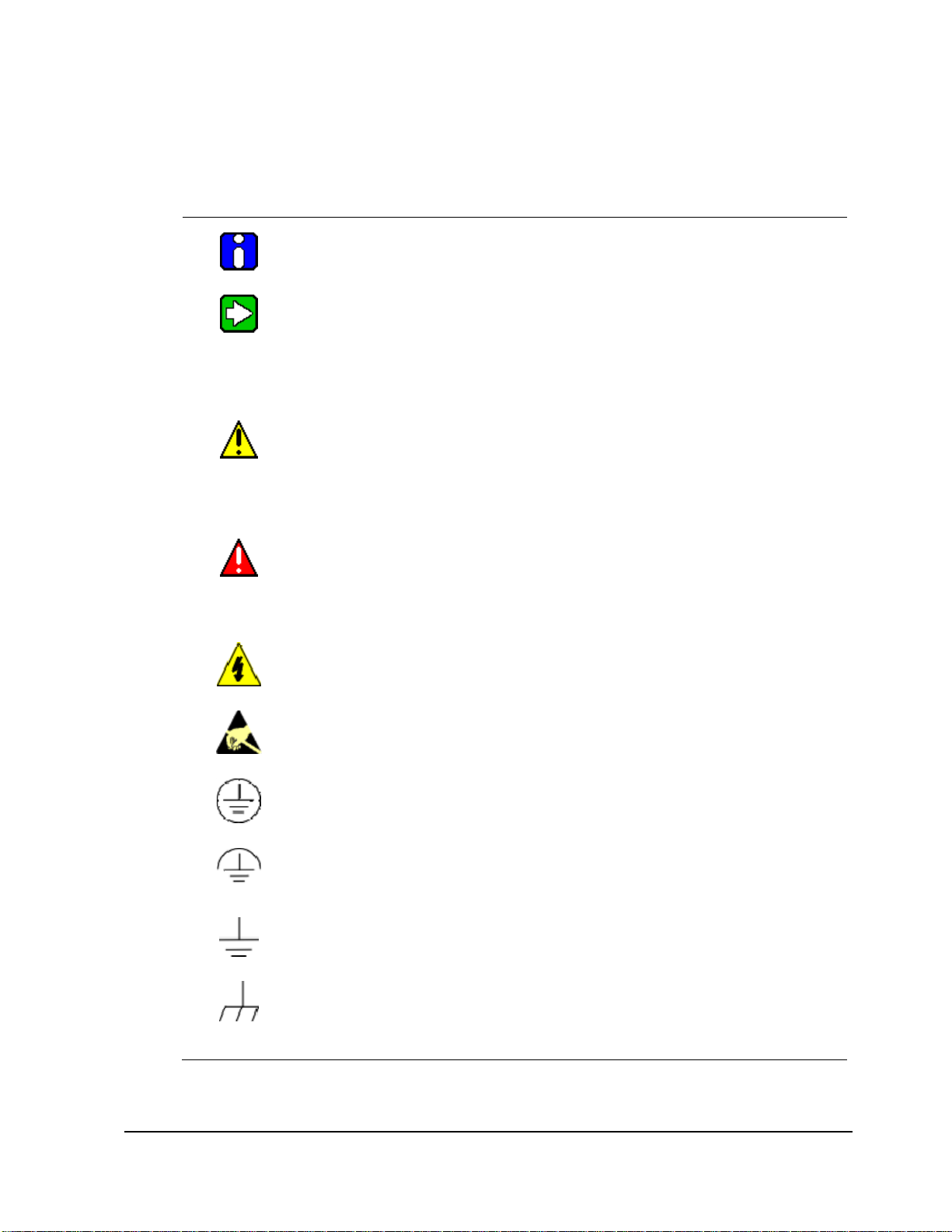
Symbol Definitions
The following table lists those symbols used in this document to denote certain conditio ns.
Symbol Definition
CAUTION
continued
ATTENTION: Identifies information that requires special consideration.
TIP: Identifies advice or hints for the user, often in terms of performing a task.
Indicates a situation which, if not avoided, may result in equipment or work (data) on
the system being damaged or lost, or may result in the inability to properly operate
the process.
CAUTION: Indicates a potentially hazardous situation which, if not avoided, may
result in minor or moderate injury. It may also be used to alert against unsafe
practices.
CAUTION symbol on the equipment refers the user to the product manual for
additional information. The symbol appears next to required information in the
manual.
WARNING: Indicates a potentially hazardous situation, which, if not avoided, could
result in serious injury or death.
WARNING symbol on the equipment refers the user to the product manual for
additional information. The symbol appears next to required information in the
manual.
WARNING, Risk of electrical shock: Potential shock hazard where HAZARDOUS
LIVE voltages greater than 30 Vrms, 42.4 Vpeak, or 60 VDC may be accessible.
ESD HAZARD: Danger of an electro-static discharge to which equipment may be
sensitive. Observe precautions for handling electrostatic sensitive devices.
Protective Earth (PE) terminal: Provided for connection of the protective earth
(green or green/yellow) supply system conductor.
Functional earth terminal: Used for non-safety purposes such as noise immunity
improvement. NOTE: This connection shall be bonded to Protective Earth at the
source of supply in accordance with national local electrical code requirements.
Earth Ground: Functional earth connection. NOTE: This connection shall be
bonded to Protective Earth at the source of supply in accordance with national and
local electrical code requirements.
Chassis Ground: Identifies a connection to the chassis or frame of the equipment
shall be bonded to Protective Earth at the source of supply in accordance with
national and local electrical code requirements.
Revision 1 OneWireless XYR 6000 Wireless Valve Position Sensor Quick Start Guide v
1/20/09

Symbol Definition
C-Tick Mark: The C-Tick Mark is a certification trade mark registered to ACMA
(Australian Communications and Media Authority) in Australia under the Trade Marks
Act 1995 and to RSM in New Zealand under section 47 of the NZ Trade Marks Act.
The mark is only to be used in accordance with conditions laid down by ACMA and
RSM. This mark is equal to the CE Mark used in the European Union.
Notified Body: For radio equipment used in the European Union in accordance with
the R&TTE Directive, the CE Mark and the notified body (NB) identification number is
used when the NB is involved in the conformity assessment procedure. The alert sign
must be used when a restriction on use (output power limit by a country at certain
frequencies) applies to the equipment and must follow the CE marking.
vi OneWireless XYR 6000 Wireless Valve Position Sensor Quick Start Guide Revision 1
1/20/09

Contents
Support and contact info........................................................................................................................ iv
1. INTRODUCTION .................................................................................................... 1
1.1 Site preparation ............................................................................................................................. 1
1.2 European Union Usage ................................................................................................................. 1
1.3 Certifications and approvals ........................................................................................................ 2
Hazardous location certifications ............................................................................................................................ 2
Radio certifications ................................................................................................................................................. 2
Ratings ................................................................................................................................................................... 3
2. SENSOR MOUNTING ............................................................................................ 5
2.1 Weight ............................................................................................................................................ 5
2.2 Dimensions .................................................................................................................................... 5
2.3 Sensor location ............................................................................................................................. 7
WCX Valve Position Sensor models....................................................................................................................... 7
2.4 Bracket mounting .......................................................................................................................... 8
Orientation .............................................................................................................................................................. 8
Attach bracket to pipe ............................................................................................................................................. 8
Attach sensor to valve ............................................................................................................................................ 9
Attach sensor to bracket ....................................................................................................................................... 10
3. PROCESS INSERTION ....................................................................................... 11
3.1 Basic Requirements .................................................................................................................... 11
Non-sparking Considerations ............................................................................................................................... 11
Distance from Multinode ....................................................................................................................................... 11
Angle to be measured .......................................................................................................................................... 11
Sensor update rate ............................................................................................................................................... 11
Access to cover for configuring sensor, changing batteries .................................................................................. 11
Proximity to high powered L-band transmitters .................................................................................................... 11
3.2 Linkage Alignment ...................................................................................................................... 12
Axis of valve and sensor input shaft ..................................................................................................................... 12
Alignment of linkage ............................................................................................................................................. 12
If angle linearity is required ................................................................................................................................... 12
Coupling with pulleys ............................................................................................................................................ 13
If clockwise is to be translated into counter clockwise .......................................................................................... 13
3.3 Non-Valve Applications .............................................................................................................. 14
Door Position Sensing .......................................................................................................................................... 14
Air Handler Plenum Door Position Sensing .......................................................................................................... 14
Linear Displacement ............................................................................................................................................. 14
4. ANTENNA ADJUSTMENT AND MOUNTING ..................................................... 15
4.1 Requirements .............................................................................................................................. 15
Radio installation requirements ............................................................................................................................ 15
4.2 Integral antenna ........................................................................................................................... 15
Elbow .................................................................................................................................................................... 16
Revision 1 OneWireless XYR 6000 Wireless Valve Position Sensor Quick Start Guide vii
1/20/09

50BContents
52BSymbol Definitions
Straight ................................................................................................................................................................. 16
5. START UP ........................................................................................................... 17
5.1 Connect batteries ........................................................................................................................ 17
5.2 Display sequence ........................................................................................................................ 19
5.3 Authentication ............................................................................................................................. 19
5.4 Calibration .................................................................................................................................... 19
6. INSTALLATION DRAWINGS .............................................................................. 21
6.1 Drawing Availability .................................................................................................................... 21
viii OneWireless XYR 6000 Wireless Valve Position Sensor Quick Start Guide Revision 1
1/20/09

50BContents
53BTables
Tables
Table 1 Battery Connecting Procedure ....................................................................................................... 17
Revision 1 OneWireless XYR 6000 Wireless Valve Position Sensor Quick Start Guide ix
1/20/09

50BContents
54BFigures
Figures
Figure 1 WCX Valve Position Sensor dimensions......................................................................................... 5
Figure 2 WCX Valve Position Sensor rt. angle antenna dimensions ............................................................ 6
Figure 3 WCX Valve Position Sensor straight antenna dimensions.............................................................. 7
Figure 4 Common bracket orientations ......................................................................................................... 8
Figure 5 Sensor Mounted Above Valve ......................................................................................................... 9
Figure 6 Axis Parallel and Linkage 90 degrees with shafts ......................................................................... 12
Figure 7 Parallelogram formed by linkage ................................................................................................... 13
Figure 8 Changing CW into CCW ................................................................................................................ 14
Figure 9 Elbow antenna adjustment ............................................................................................................ 16
Figure 10 Integral straight antenna .............................................................................................................. 16
Figure 11 Battery connecting ....................................................................................................................... 18
Figure 12 Battery connecting detail ............................................................................................................. 18
x OneWireless XYR 6000 Wireless Valve Position Sensor Quick Start Guide Revision 1
1/20/09
 Loading...