

Page 1

4909 CPVC Conductivity Cell
Insertion/Removal Assembly
Operations Manual
70-82-25-19
Rev. 1
7/99
Page 2

Copyright, Notices, and Trademarks
Printed in U.S.A. – © Copyright 1999 by Honeywell Inc.
Revision 1– 7/99
While this information is presented in good faith and believed t o be
accurate, Honeywell disclaims the implied warr ant ies of
merchantability and fitness for a part icular pur pose and m akes no
express warranties except as may be stated in its wr itten agreement
with and for its customer.
In no event is Honeywell liable to anyone for any indirect, special or
consequential damages. The information and specifications in t his
document are subject to change without notice.
Honeywell
Industrial Automation and Control
Automation College
2820 West Kelton Lane
Phoenix, AZ 85023
(602) 313-5669
ii 4909 CPVC Conductivity Cell Insertion/Removal Assembly– Operations Manual 7/99
Page 3

About This Document
Abstract
The purpose of this document is to support the installation operation and maintenance of the 4909 CPVC
Conductivity Cell Removal/Insertion Assembly.
Revision Notes
The following list provides notes concerning all revisions of this document.
Rev. ID Date Notes
0 11/96 This revision is the initial release of the Honeywell version of the L&N manual
p/n 277731 Rev. E1. There were no major changes to the L&N version when
it was Honeywellized.
1 6/99 Edits were made to standardize terminology and to add the new Model
Selection Guide.
References
Honeywell Documents
The following list identifies all Honeywell documents that may be sources of reference for the material
discussed in this publication.
Document Title ID #
9782 Series Conductivity/Resistivity Analyzer/Controller Operator’s Manual 70-82-25-74
7079-17 Two-Wire Transmitter for Conductivity/Resistivity Operation and
Maintenance Manual
Non-Honeywell Documents
70-82-25-51
The following list identifies select non-Honeywell documents that may be sources of reference for the
material discussed in this publication.
Title Author Publisher ID/ISDN #
Contacts
The following list identifies important contacts within Honeywell.
7/99 4909 CPVC Conductivity Cell Insertion/Removal Assembly– Operations Manual iii
Page 4

Organization Telephone Address
Honeywell TAC 1-800-243-9883 Voice 1100 Virginia Drive
Fort Washington, PA 19034
iv 4909 CPVC Conductivity Cell Insertion/Removal Assembly– Operations Manual 7/99
Page 5

Contents
1. INTRODUCTION....................................................................................................1
1.1 Overview.........................................................................................................................................1
1.2 4908 Conductivity Cell...................................................................................................................1
1.3 31074357 Removal Device............................................................................................................2
2. SPECIFICATIONS AND MODEL SELECTION GUIDE.........................................7
2.1 Specifications..................................................................................................................................7
Cell Constants....................................................................................................................................7
Electrode Material.............................................................................................................................7
Wetted Parts.......................................................................................................................................7
Pressure and Temperature (See Fig. 1-1)..........................................................................................7
Maximum Pressure............................................................................................................................7
Mounting ...........................................................................................................................................7
Purge Port..........................................................................................................................................7
Insertion Depth..................................................................................................................................7
Electrical Connections.......................................................................................................................7
Integral Automatic Temperature Compensation ...............................................................................8
Leadwire............................................................................................................................................8
Weight ...............................................................................................................................................8
2.2 Model Selection Guide ...................................................................................................................8
...........................................................................................................................................................8
3. INSTALLATION...................................................................................................11
3.1 Requirements................................................................................................................................11
3.2 Location and Position ...................................................................................................................11
Considerations.................................................................................................................................11
3.3 Prepare Assembly.........................................................................................................................12
Initial Prep.......................................................................................................................................12
Mounting into the Process...............................................................................................................12
3.4 Insertion........................................................................................................................................13
3.5 Removal........................................................................................................................................14
3.6 Electrical Connections..................................................................................................................14
7/99 4909 CPVC Conductivity Cell Insertion/Removal Assembly– Operations Manual v
Page 6

4. MAINTENANCE AND REPLACEMENT PARTS .................................................17
4.1 To Clean The Cell.........................................................................................................................17
4.2 Replacing Removal Device Parts..................................................................................................17
Ball Valve........................................................................................................................................17
Nipples.............................................................................................................................................17
Bushing And Washer.......................................................................................................................17
4.3 Replacement Parts.........................................................................................................................18
5. PLATINIZATION AND PLATINUM BLACK.........................................................19
vi 4909 CPVC Conductivity Cell Insertion/Removal Assembly– Operations Manual 7/99
Page 7

Tables
Table 4-1 Replacement Parts __________________________________________________________ 18
Table 4-2 Voltage and Time Limits for Platinizing Cells ____________________________________ 18
Figures
Figure 1-1 Temperature/Pressure* Range__________________________________________________ 2
Figure 1-2 4909 CPVC Conductivity Cell Insertion/Removal Assembly with Conductivity Cell Installed3
Figure 1-3 4909 CPVC Conductivity Cell Insertion/Removal Assembly with Universal Head_________ 3
Figure 1-4 4908 Conductivity Cell _______________________________________________________ 4
Figure 1-5 31074357 Removal Device ____________________________________________________ 4
Figure 1-6 Universal Head_____________________________________________________________ 5
Figure 3-1 Outline and dimension drawing for 4909-X-X-X-X-03-X-X Conductivity Cell, Insertion Type
with CPVC Removal Device _______________________________________________________ 15
Figure 3-2 Outline and Dimension drawing for 4909-X-X-X-X1-03-X-X Conductivity Cell, Insertion
Type with CPVC Removal Device and Universal Head __________________________________ 16
Figure 5-1 Installation Diagram-Cat. 4909 Cells with Junction Box Head Connected to 7082
Conductivity/Resistivity Analyzer___________________________________________________ 20
Figure 5-2 Installation Diagram-Cat. 4909 Cells with Junction Box Head Connected to 9782
Conductivity/Resistivity Analyzer___________________________________________________ 21
Figure 5-3 Installation Diagram-Cat. 4909 Cells with 7 or 20 Foot Leads Connected to 7082
Conductivity/Resistivity Analyzer___________________________________________________ 22
Figure 5-4 Installation Diagram-Cat. 4909 Cells with 7 or 20 Foot Leads Connected to 9782
Conductivity/Resistivity Analyzer___________________________________________________ 23
7/99 4909 CPVC Conductivity Cell Insertion/Removal Assembly– Operations Manual vii
Page 8

Page 9

1.1 Overview
The 4909 Conductivity Cell Insertion/Removal Assembly is designed for use in a pipeline or closed vessel
where it is desirable to remove the cell for inspection and maintenance without shutting down the system
and releasing the pressure. The assembly comprises a 4908 Conductivity Cell and a 31074357 Removal
Device which are shown assembled in Figs. 1-2 and 1-3. It is to be used in applications for which
maximum pressure does not exceed 125 psig, and can be reduced to 50 psig during insertion and removal of
the cell. Maximum operating temperature is determined by the temperature compensator range. Do not use
in solutions above 80°C.
The depth of insertion is given in Figs. 3-1 and 3-2.
The conductivity cell is made of polyethersuflone (PES), which is resistant to most corrosive inorganic
chemicals over a wide range of temperatures (common exceptions are chlorinated hydrocarbons and
ketones). Sample solutions come into contact with the PES and the platinum or nickel electrode surface of
the cell. (Any cell constant can be supplied with either electrode material). The only materials of the 4909
Assembly with which the sample solution may come into contact are in the removal device which is
comprised of CPVC plastic, Teflon, EPDM and Viton materials. The automatic temperature compensator
may be built into the cell as shown in Section 2.2, Model Selection Guide.
Introduction
1. Introduction
CAUTION
Specific parameters of your process may prohibit the use of nickel electrodes. For example, always use a
platinum cell (Table II = 44) if the cell will measure or be exposed to regeneration acids or bases.
1.2 4908 Conductivity Cell
The molded conductivity cell and its one-inch diameter by 3-inch long adapter comprise a one piece cell
unit and are made of polyethersulfone (PES). This adapter serves as a stop during the removal operation.
The cell can be supplied with a two, three or four conductor, Tefzel-sheathed cable, Fig. 1-2. Either of two
different lengths of cable can be furnished as specified in the Model Selection Guide (MSG) number, see
Section 2.2, Model Selection Guide. Or the insertion/removal assembly can be supplied with a Universal
Head, Fig. 1-3.
-1
The cells having constants of 5, 10, 20, 25 or 50 cm
conductive solutions. They differ in constructio n from those having constants of 0.01, 0.1, or 1. On the 5
to 50 constant cells, the electrodes are short tubes located midway inside the two parallel tubular channels
that run lengthwise through the cell, and are open to the sample at both ends of the cell. The channels are
larger on the 25 constant cell and they are elliptical on the 5 and 10 constant cell. The 0.0 1, 0.1, and 1.0
constant cells have a removable cell guard which is screwed onto the cell body to protect the electrode
surfaces. Cells with a guard tube must be used with the guard in place or the cell constant may differ from
that specified. Electrodes are three discs on the 1 constant cell, parallel plates on the 0.1 constant cell, and
a pair of concentric wires wound on the cell body on the 0.01 constant cell.
are intended for making measurements in highly
7/99 4909 CPVC Conductivity Cell Insertion/Removal Assembly– Operations Manual 1
Page 10
4909 CPVC Conductivity Cell Insertion/Removal Assembly Operations Manual
1.3 31074357 Removal Device
This device consists of a ball valve which is connected to the closed system by a 1-1/2 inch CPVC schedule
80 mounting nipple and to a housing by a 6 inch long schedule 80 CPVC nipple into which the support tube
for the cell mounting is inserted. The compression handle provides a seal around the cell support tube.
Depending on the Key Number selected in Section 2.2, MSG, the 31074357 Removal Device may or may
not include the 4908 Cell preinstalled in the device.
If Key Number 04908 is selected, the 4908 Cell (Fig. 1-4) is shipped apart from the removal device.
If Key Number 04909 is selected, the 4908 Cell is preinstalled into the removal device, Fig. 1-3. Details of
each type of installation are given in Section 3.3.
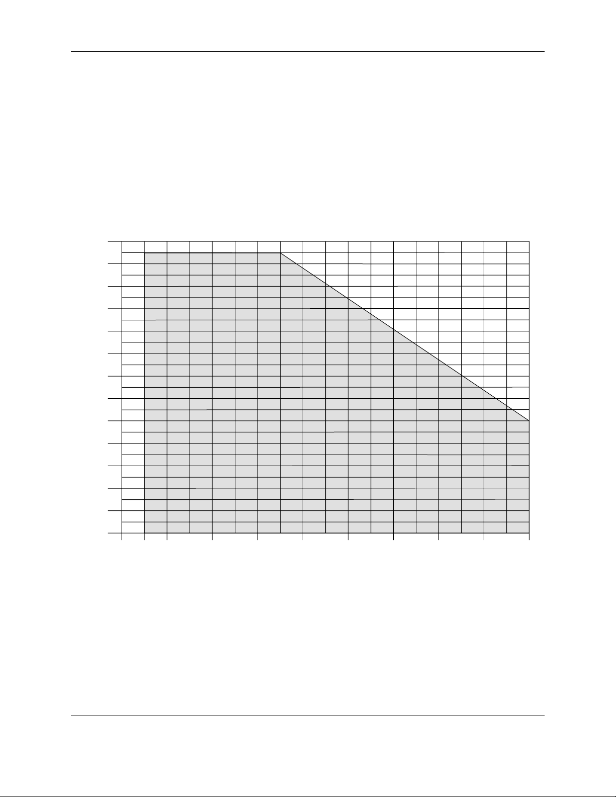
130
120
110
100
90
80
70
PSIG
60
50
40
30
20
10
0
-10 -5 0 10 20 30 40 50 60 70 80
DEGREES CELSIUS
a/n 23349
Figure 1-1 Temperature/Pressure* Range
* 50 psig max. during insertion or removal of 4908 cell.
2 4909 CPVC Conductivity Cell Insertion/Removal Assembly– Operations Manual 7/99
Page 11
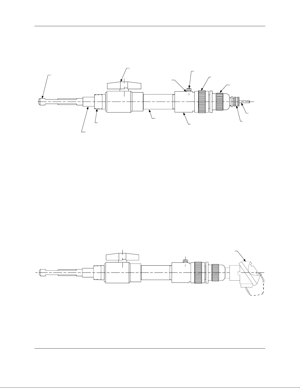
Introduction
Conductivity Cell
Valve
1/4" NP T Plug
Purge Port
Compression Handle
Support Grip
6" Nipple
1-1/2" NPT Nipple
Housing
Adapter (Contains Automati c Temperat ure Compensator when Specified)
Figure 1-2 4909 CPVC Conductivity Cell Insertion/Removal Assembly
with Conductivity Cell Installed
Cable
Cable Grip
a/n 23350
Universal Head Assembly
a/n 23351
Figure 1-3 4909 CPVC Conductivity Cell Insertion/Removal Assembly with Universal Head
7/99 4909 CPVC Conductivity Cell Insertion/Removal Assembly– Operations Manual 3
Page 12

4909 CPVC Conductivity Cell Insertion/Removal Assembly Operations Manual
Conductivity
Cell
Adapter *
* Automatic Temperatur e Compensator,
when specified by catalog number, is
mounted inside adapter.
Figure 1-4 4908 Conductivity Cell
Do no t n i c k
outside of
support tube
Note: Apply a thin film of Silicone grease
to all surfaces of bushing and to
diameter of support tube as shown.
Apply grease
(See Note above)
Cable
a/n 23352
Modify per sketc h*
Tighten securely to pipe
Apply teflon tape to
bot h e nds of supp ort
tube. Tight en all pi pe
thread fittings two turns
beyond hand tight.
Slice through one
side as shown
These parts should be
hand-tighten ed only
*
Compression
Bushing
Figure 1-5 31074357 Removal Device
4 4909 CPVC Conductivity Cell Insertion/Removal Assembly– Operations Manual 7/99
a/n 23353
Page 13

Introduction
Nipple (3/4" NPT)
Set Screw
Base
#6-32 Screw
Wire
Gas ket
Cap
#6-32 Screw
C
O
N
D
U
C
T
I
V
I
T
Binding Head
Chain
Y
C
E
L
L
#6-32
Screw &
Washer
Terminal
Board
Assembly
A
D
CB
View of B a s e
with Cap Removed
a/n 23354
Figure 1-6 Universal Head
7/99 4909 CPVC Conductivity Cell Insertion/Removal Assembly– Operations Manual 5
Page 14

4909 CPVC Conductivity Cell Insertion/Removal Assembly Operations Manual
6 4909 CPVC Conductivity Cell Insertion/Removal Assembly– Operations Manual 7/99
Page 15

2. Specifications and Model Selection Guide
2.1 Specifications
Cell Constants
0.01, 0.1,1.0, 5, 10, 20, 25 and 50 cm
Electrode Material
Nickel or Platinum, as specified.
Wetted Parts
Cell Body: Polyethersulfone ( PES).
Electrodes: See above.
Mounting Materials: Chlorinated Polyvinyl Chloride (CPVC).
Internal Sealing Materials: Viton, Teflon & EPDM
Specifications and Model Selection Guide
-1
.
Pressure and Temperature (See Fig. 1-1)
125 psig (862 kPa) max. @ 23°F (-5°C)
90 psig (621 kPa) max. @ 122°F (50°C)
50 psig (345 kPa) max. @ 176°F (80°C)
Maximum Pressure
During Insertion or Removal: 50 psig.
Mounting
1-1/2” NPT male pipe. Overall length of removal device: approximately 20 or 22 inches (allow additional
clearance for cell withdrawal). See Figs. 3-1 and 3-2.
Purge Port
1/4” NPT female opening.
Insertion Depth
Varies between 4.5” and 6.8” nominal, depending upon cell constant. Greater insertion depths are optional.
See Figs. 3-1 and 3-2.
Electrical Connections
Three leads with integral automatic temp. compensator. Two leads without integral automatic temp.
compensator. Four leads with integral automatic temp. compensator)Table III = 333).
7/99 4909 CPVC Conductivity Cell Insertion/Removal Assembly– Operations Manual 7
Page 16

4909 CPVC Conductivity Cell Insertion/Removal Assembly Operations Manual
(Note 3)
(Note 3)
TABLE I
(Ref
Integral Automatic Temperature Compensation
Refer to Section 2.2 – Model Selection Guide
Leadwire
Tefzel covered, 18-gage cable (7 feet, 20 feet, or Universal Head, as specified).
Weight
Approximately 3.5 lb (1.6 Kg) (including cell).
2.2 Model Selection Guide
KEY NUMBER Selection Availability
04909 Complete Conductivity Cell Assembly
04908 Replacement Cell Only
Cell Constant 1 XX1
TABLE II
Electrode Material Nickel 33
TABLE III
Automatic Temperature Compensator (ATC)
No Temperature Compensator 000
Available for 9782 and 7082 Only 333
Available for 7079C Transmitter or already withdrawn analytical 072
instrumentation.
Appropriate Conductivity Instrumentation & Cells for available
Temp. Compensator/Conductivity range.) 093
Description
(Note 2)
(Note 1)
0.01 001
0.1 X01
5 XX5
10 X10
20 X20
25 X25
50 X50
Platinum 44
er to Tables 1 and 6 under Steps to Selecting
04909
04908
gg
gg
ff
009
013
014
071
073
074
088
090
091
113
114
160
164
168
8 4909 CPVC Conductivity Cell Insertion/Removal Assembly– Operations Manual 7/99
Page 17

Specifications and Model Selection Guide
049
TABLE IV Selection 09 08
Leadwire Length ’7 ft. Leadwire X7
20 ft. Leadwire 20
Junction Head (Aluminum) X1
TABLE V
Valve/Cell Material Material
4909 Stainless Steel (SS) Valve Includes SS Valve assembly and 02
c
Assembly Standard insertion cell
4908 PES Replacement Cell for Standard insertion cell only 02
4909 SS Valve Assembly
4909 CPVC Valve Assembly Includes CPVC assembly and 03
d
standard CPVC Support tube
(15 3/8") and cell
4908 PES Replacement Cell for Cell only 03
CPVC Valve Assembly
TABLE VI
Special Mounting Options - select one option per unit
None 000
SS support tube for 4909 SS Valve 930
e
assemblies only. Use Table V
Option = 02
4908 replacement cells for 4909 SS 930
Valve Assembly containing SS Support
tube. Use Table V Option = 02
Special insertion lengths for new/ Uses special insertion cell to 910
hh
replacement cells for 4909 SS increase standard insertion
Valve Assemblies. Only available cell depth by 4.4"
for Table V Option = 02 Uses special insertion cell to 920
increase standard insertion
cell depth by 8.8"
(Note 4)
Uses special insertion cell to 925
increase standard insertion
cell depth by 13.2"
Uses special insertion cell to 940
(Note 4)
hh
decrease standard insertion
cell depth by 4.4"
Extended Length CPVC Support tube. Supplies special CPVC 950
j
Only available for Table V Option = 03 support tube (21 3/8") to
increase cell insertion depth
by 6.0" in a new CPVC Valve
Assembly. Note: Allow
additional 6.0" for cell removal
c
d
e
7/99 4909 CPVC Conductivity Cell Insertion/Removal Assembly– Operations Manual 9
Page 18

4909 CPVC Conductivity Cell Insertion/Removal Assembly Operations Manual
TABLE VII - OPTIONS
Tagging None 0_
Linen L_
Stainless Steel
Certificate of Calibration No _ 0
Yes
Notes:
Replacement cells only, caution look at Restrictions for insertion depth dimensions based on valve
1.
assembly type.
When converting from 4806 to 4909, order 4908 directly.
2.
Replacement 4908 cells for existing 4908’s and 4909’s manufactured before 8/85 must specify Table V = 02.
3.
This option is application sensitive. You must contact Analytical Instruments Marketing for approval.
4.
RESTRICTIONS
Restriction Letter Available Only With Not Available With
Table Selection Table Selection
c
V Standard insertion cell for SS valve assemblies consists of a conductivity
cell of variable length based on the cell constant and a 13.2" PES tube
molded to the cell. The conductivity cell insertion depth is listed below:
049
S_
_ 1
d
e
f
V Standard conductivity cell insertion depth dimensions according to cell
V 02 I X25, X50
III For 9782 and 7082 Analyzers only
g
h
j
V02
V03
001, X01, XX1 = 7.5"
XX5 = 6.5"
X10 = 7.7"
X20 = 8.0"
X25, X50 = 8.8"
constants for CPVC assemblies is listed below:
001, X01, XX1 = 5.5"
XX5 = 4.5"
X10 = 5.7"
X20 = 6.0"
X25, X50 = 6.8"
I Not for 9782 and 7082 Analyzers
10 4909 CPVC Conductivity Cell Insertion/Removal Assembly– Operations Manual 7/99
Page 19

3.1 Requirements
To insure that a representative sample is being measured at all times, the solution must move through and
completely purge out the cell channels or guard tube. If the measurement is made in a rapidly moving
liquid, the existing circulation of the solution can be utilized by mounting the assembly as described in the
next section so that the flow of the solution forces liquid through the cell. However, when measurements
are to be made in quiescent solutions, means must be provided for forcing the solution through the
conductivity cell so no air bubbles accumulate or care taken to place the cell in a position to measure the
true value of the solution.
Do not use the cells in solutions which will attack the fittings used or the wetted cell materials. The PES
and platinum or nickel of the electrode are the cell materials with which the solution will come into contact.
The wetted materials of the removal device with which the process may come into contact with are CPVC,
Teflon, EPDM and Viton.
Do not use the cell in a solution having temperatures greater than 80°C. The maximum limit set by the
temperature compensator range must be observed.
Installation
3. Installation
For cells having a constant of 0.01, 0.1 or 1, make certain that the guard is in place and is not loose on the
cell body. The guard tube must be hand-tightened only. There is a 1/16 inch space between the guard tube
and the cell body.
Do not install the 4909 Assembly where pressures and/or temperatures may occur outside the operating
range given in Fig. 1-1. Both pressure and temperature must be within the shaded area of the curve.
Avoid installations where the 4909 Assembly will be exposed to pressure shock caused by water hammer.
3.2 Location and Position
Refer to Fig. 3-1 or Fig. 3-2 for mounting dimensions.
Considerations
The cross-channel in the high constant cells or the guard tube holes in the low constant cells must be
covered by the solution during measurements.
Vertical insertion (from above) or horizontal insertion can be used. Make certain the tank or pipeline is full
under all process conditions. If a pipeline is not always full, use a vertical mounting and insert the cell far
enough into the vertical pip e that the cross-channel is below the hori z ontal exit pipe which may empty out.
Make certain an air bubble in the pipe does not prevent the cell from filling properly. (If the cell becomes
dry after use, it may require cleaning in accordance with Section 4.1 before again being placed in service.)
For best results, whether vertical or horizontal mounting is used, position the cell so that the sample will
flow through the channels or guard tube towards the mounting end of the ce ll, exiting through the crosschannel or guard-tube holes. In applications where vertical mounting is required, avoid a position with the
cell channels pointed up, as this will permit solution to flow down into the open end of the cell and may
result in clogging by solids settling in the cell channels.
Allow for insertion depth from the outside wall of the mounting surface as indicated by the dimensions in
Fig. 3-1 or 3-2.
7/99 4909 CPVC Conductivity Cell Insertion/Removal Assembly– Operations Manual 11
Page 20

4909 CPVC Conductivity Cell Insertion/Removal Assembly Operations Manual
Allow at least 1/2 inch clearance beyond the end of the cell and 1/8 to 3/16 inch radius clearance
surrounding the cell to permit circulation of the solution.
Avoid locations where excessive temperature changes may occur.
Allow clearance behind the support grip to permit removal of the cell per dimensions in Fig. 3-1 or 3-2.
Locate the insertion/removal assembly on the pressure side of pumps; not the vacuum side.
Avoid locations where the operator must take an awkward position to perform the cell insertion or removal
operation.
The 4909 Insertion/Removal Assembly is designed to support only its own weight. Do not install in
locations where it would be used as a foot rest or where it would b e used as a hand grip. Do not hang or
support any other piping or objects from the assembly.
The removal device should not be mounted onto pipelines or vessels displaying excessive vibr a tion unless a
support is provided on the 6” long valve nipple.
3.3 Prepare Assembly
If X7 or 20 are selected in Table IV of the Model Selection Guide, then the 4908 Conductivity Cell (Fig. 1-
4) must be joined with the support tube of the 31074357 Removal Device as discussed in Section 1.3.
Refer to Fig. 1-5.
Initial Prep
1. Loosen compression handle by turning it counterclockwise until it is free from housing.
2. Withdraw the support tube, bushing, washer and handle assembly keeping the bushing and washer in
place on the support tube. When greater insertion depth of the conductivity cell into the process
solution is desired, p/n 074344 Support Tube will give an additional 6 inches immersion beyond the
standard depth. See Figs. 3-1 and 3-2. If 074344 Support Tube is to be used, it must be secured to the
support grip.
3. Slide the bushing and washer off of the standard support tube.
4. Turn the compression handle counterclockwise to remove it from the support grip.
5. Using a strap wrench, loosen and remove the standard support tube.
6. Install 074344 Support Tube by wrapping one end with Teflon tape overlapping by 50% on each wrap.
Wrap the tape in a clockwise direction as viewed from the threaded end of the support tube.
7. Thread this end into the support grip by hand and tighten an additional two turns by using a strap
wrench. Do not use stillson or chain type wrenches as they may damage or score the support tube and
prevent a good seal with the bushing.
8. Replace the compression handle, washer and bushing removed earlier. Note the proper orientation of
the bushing with the tapered surface facing away from the compression handle.
Mounting into the Process
The valve nipples and housing can now be mounted into the process pipeline or tank wall.
1. Remove the protective cap and apply Teflon tape to mounting nipple. Wrap the tape on the threads in a
clockwise direction as viewed from the threaded end. Overlap the tape by 50% on each wrap. Cover
the threaded area twice in this manner.
2. Install the mounting nipple and valve assembly hand tight.
12 4909 CPVC Conductivity Cell Insertion/Removal Assembly– Operations Manual 7/99
Page 21

Installation
3. Using a strap wrench on the mounting nipple, tighten the assembly an additional 1-1/2 to 2 turns. Do
not use stillson or chain type wrenches as they may damage and weaken the CPVC plastic. Do not use
the valve handle for leverage.
4. Close the ball valve; handle perpendicular to valve.
A purge port is provided on the removal device housing. Water or some other fluid source can be piped to
this port for the purpose of cleaning out the valve assembly from accumulated debris. For most
conductivity applications, the process stream will not have high particle content and the purge port is not
used.
If purging is required remove plug and install a purge line to the ¼” NPT opening. Note that the purge fluid
temperature and pressure must not exceed the 4909 Assembly temperature and pressure specifications as
shown in Fig. 1-1. Also, the purge line must have a shutoff valve located near the removal device.
Another use for the purge port can be realized if a pressure gage is installed in the ¼” NPT o pening. It will
serve as a local indication of process pressure to confirm that the pressure is below 50 psig during insertion
or removal of the cell.
Make sure the bushing and washer are in place on the support tube, then feed the cable of the 4908
Conductivity Cell through the support tube and turn the tube hand tight onto the conductivity cell. Using a
strap wrench, tighten the 4908 Cell an additional 1-1/2 to 2 turns. Do not score or gouge the support tube
surface because the bushing makes a seal on the tube surface.
Tighten the cable grip to provide strain relief from the cell cable.
If X1 is selected in Table IV of the Model Selection Guide, then the 4908 Conductivity Cell has been pre-
mounted by Honeywell onto the support tube. Also cable wiring to the universal head terminal board has
been completed. The valve assembly can then be mounted to the process by following steps under
“Mounting into the Process” mentioned earlier.
3.4 Insertion
1. Make sure the bushing and washer (Fig. 1-5) are in place on the support tube. A thin film of silicone
grease is applied at the factory to the bushing and to the support tube area covered by the compression
handle. If this film has been wiped off or if dirt or grit is present, clean these areas and reapply a new
film of silicone grease (p/n 090011, 0.3 oz. tube).
2. Obtain the cell and support tube assembly prepared earlier. Separate the compression handle from the
support grip by turning the support grip counterclockwise approximately two turns. Slide the
compression handle along the support tube until the bushing and washer are sandwiched between the
handle and 4908 Cell Adapter.
3. Slide the cell and tube assembly into the removal device housing and tighten the compression handle
clockwise until drag is felt on the tube. This can be determined by rotating the tube by hand.
4. REDUCE PROCESS PRESSURE TO 50 PSIG OR LESS. Open the ball valve; handle pa rallel to
valve.
5. Push the cell and support tube assembly all the way in using the support grip.
6. Tighten the support grip by turning clockwise two turns.
ATTENTION
This step is important to prevent blow-back of cell and support tube assembly. The bushing acts as a safety
stop against the cell adapter if the support tube does blow back.
7. Return the process to normal operating pressure.
8. Further tighten the compression handle if leakage occurs from the bushing seal area.
7/99 4909 CPVC Conductivity Cell Insertion/Removal Assembly– Operations Manual 13
Page 22

4909 CPVC Conductivity Cell Insertion/Removal Assembly Operations Manual
3.5 Removal
1. REDUCE PROCESS PRESSURE TO 50 PSIG OR LESS. Shut off purge line, if used. Disconnect
wiring connections if X1 is selected for Table IV in the MSG.
2. DO NOT STAND BEHIND THE TUBE WHEN PERFORMING THIS STEP. While holding the
compression handle from turning, turn the support grip two turns counterclockwise. Loosen the
compression handle until the process pressure pushes the cell and support tube assembly out to its
internal stop. If necessary, pull out by hand until stop is reached.
3. Close the ball valve. If the valve does not close easily, make sure the support tube is pulled all the way
back.
4. Completely loosen the compression handle to withdraw the cell.
3.6 Electrical Connections
The terminal board connections for recorder or analyzer are given in the appropriate directions furnished
with the measuring instrument.
When the cell assembly includes a built-in temperature compensator, all leads are used. The cell is
connected between black and white and the compensator is between red and white, except when MSG Table
III=333. In this case, the built-in temperature compensator is between red and green. See Figs. 5-1 and 5-2
when wiring cells with MSG option=333.
To avoid the possibility of ac pick-up in the cell leads, separate them from all AC line voltage wiring or run
them in a separate grounded conduit.
Cells are available with leadwire up to 20 feet as specified in the MSG assembly. For distances greater than
20 feet, use the required length of cable and a junction box, both listed in Section 4.3. For assemblies
supplied with a Universal Head, Fig. 3-2, a junction box is not required.
14 4909 CPVC Conductivity Cell Insertion/Removal Assembly– Operations Manual 7/99
Page 23

Installation
)
X "
See Below
* Standard Insertion Depth
Table I
X" Approx.
001
0 1
1
5
1 0
20
25
50
* Add 6" (152 mm) to
Dimensions if 074344
Support Tube is Used.
0.940"
Dia
(24mm)
4.5
5.7
6.0
6.8
6.8
5.5
5.5
5.5
mm
140
140
140
114
145
152
173
173
1 1/2 NPT
Schedule 80 Nipple
Temp.
Comp.
Cell
Concentration Ranges
RED
WHITE
BLACK
Linear Micromho,
Resistivity, or
Approx 4.1"
(105mm)
Approx 12.5"
(317mm)
Shunt
Comp.
Series
Comp.
Cell
Non-Linear
Micromho Ranges
Approx 19.7" max.
(502mm)
2.5"
(64mm)
RED
WHITE
BLACK
Cell
Without Tem p .
Compensation
1/4" NPT
Purge connection. Do not
exceed Temp./Press.
specifications of removal
device
Temp.
WHITE
BLACK
Comp.
Cell
Linear Ranges
RED
GREEN
WHITE
BLACK
Allow a minimum
clearance of 36"
(914 mm) beyond
this point for
removal of
electrode.
Allow 42" (1067mm
if alternate support
tube is used.
Electrode Cable,
approx 0.25" (6.4mm)
O.D. max with 2, 3, or
4 conduct or s of
#18 AWG wire
a/n 23355
Figure 3-1 Outline and dimension drawing for 4909-X-X-X-X-03-X-X Conductivity Cell,
Insertion Type with CPVC Removal Device
7/99 4909 CPVC Conductivity Cell Insertion/Removal Assembly– Operations Manual 15
Page 24

4909 CPVC Conductivity Cell Insertion/Removal Assembly Operations Manual
X "
See Below
* Standard Inser t i on Depth
Suffix A
X" Approx.
001
0 1
1
5
1 0
20
25
50
* Add 6" (152 mm) to
Dimensions if 074344
Support Tube is Used .
0.940"
Dia
(24mm)
5.5
5.5
5.5
4.5
5.7
6.0
6.8
6.8
Temp.
Comp.
Cell
Linear Micro mho,
Concentration Ranges
mm
140
140
140
114
145
152
173
173
RED
WHITE
BLACK
Resistivity, or
Approx 4.1"
(105mm)
1-1/2" NPT
Schedule 80 Ni ppl e
Shunt
Comp.
Series
Comp.
Cell
Micromho Ranges
Approx 12.5"
(317mm)
RED
WHITE
BLACK
Non-Linear
Approx 19.7" max.
(502mm)
2.5"
(64mm)
Cell
Cell Wiri n g
WHITE
BLACK
Without Temp.
Compensation
1/4" NPT
Purge connection. Do not
exceed Temp./Press.
specifications of removal
device
1/2" female NPT for user’s
flexible electrical conduit
connection. For insertion or
removal of cell, dis c onnect
conduit connections.
Temp.
Comp.
Cell
RED
GREEN
WHITE
BLACK
Linear Ra ng e s
(Table III = 333)
Allow a minimum
clearanc e of 36"
(914 mm) beyond
this point for
removal of
electrode.
Allow 42" (1067mm)
if al tern ate su pp o r t
tube is used.
(76mm)
3"
a/n 23346
Figure 3-2 Outline and Dimension drawing for 4909-X-X-X-X1-03-X-X Conductivity Cell,
Insertion Type with CPVC Removal Device and Universal Head
16 4909 CPVC Conductivity Cell Insertion/Removal Assembly– Operations Manual 7/99
Page 25

Maintenance and Replacement Parts
4. Maintenance and Replacement Parts
If a series of below normal conductivity readings or above normal resistivity readings occur, this may
indicate that the cell is not filled with process solution. Check the cell installation. Refer to Sections 3.1
and 3.2.
The only maintenance which may be required is occasional cleaning in certain applications. The 0.01, 0.1,
and 1.0 cm
-1
low constant electrodes are not platinized.
4.1 To Clean The Cell
CAUTION
The cell assembly is PES (polyethersulfone). Do not clean with acetone, chloroform, toluene, benzene, or any
chlorinated hydrocarbon.
The cell will require cleaning if sludge, slime, etc., accumulates in the flow channels. Since the materials of
construction are chemically inert, chemical agents may be used and are recommended for cleaning the cells.
The particular cleaning agent used must be selected according to the type of contamination to which the cell
is exposed. In general, soap and hot water cleaning solution is effective. Immerse the plastic body of the
cell in this solution. A 10 or 15 minute soaking period should be adeq uate. If necessary, a soft bristle brush
of appropriate diameter may be used to clean out the tubular channels of the 5, 10, 20, 25 and 50 constant
cells. Care must be taken not to scratch the electrode surfaces. Do not use a brush on the low (0.01, 0.1
and 1) constant cells and be especially careful not to bend the electrode plates of the 0.1 constant cell.
Rinse the cell thoroughly in tap water and then in distilled water if available. To remove the platinum black
from electrodes (5 to 50 constants only), refer to Section 5. Replatinizing after each cleaning (5 to 50
constant cells only) may not be necessary unless brushing was used.
4.2 Replacing Removal Device Parts
Ball Valve
If a new ball valve is installed, orient the valve body so that the heavy walled end is toward the process
connection for added support strength. See Teflon tape note below.
Nipples
If nipples are replaced, use exact replacement to ensure pressure and temperature ratings, proper immersion
length and proper operation of removal device.
Use only Teflon tape on all valve, nipple and support tube pipe threads. Other liquid or paste sealants may
contain solvents that weaken the CPVC material.
Bushing And Washer
Replace these parts if swollen, cracked or damaged in a way that prevents a good seal on the support tube.
Lightly grease the new bushing with silicone grease before installing.
Note that the support grip must be removed from the support tube before replacing the bushing and/or
washer. Orient the bushing so that the tapered surface faces away from the compression handle, Fig. 1-5.
7/99 4909 CPVC Conductivity Cell Insertion/Removal Assembly– Operations Manual 17
Page 26

4909 CPVC Conductivity Cell Insertion/Removal Assembly Operations Manual
4.3 Replacement Parts
Table 4-1 Replacement Parts
Description Part Number
Complete Assembly See Figs. 1-5 and 1-6
Cell Assembly Cat. 4908
Complete CPVC Removal Device 31074357
Universal Head Parts See Fig. 1-6
Platinizing Solution (3 oz. bottle) 31103011
Cell Guard Tube (0.01, 0.1, and 1.0 Constants Only) 065602
Support Tube, 1/2” NPT Sch. 80, CPVC (12” Immersion) 074344
Support Tube, 1/2” NPT Sch. 80, CPVC (6” Immersion) 074343
Junction Box 31316260
Cell Extension Leadwire (Table III other than 333)
Three conductor 18 gage cable PVC (105°C max.) 834059
Three conductor 18 gage cable Tefzel (150°C max.) 834086
9782/7082 Standard Ranges
Up to 500 ft.
Three conductor, 18 gage cable (Belden 9493) 834059
and Coax Cable (Belden 9259) 835024
Up to 1000 ft
Four conductor (3 used), 16 gage cable, 834055
Belden 9494 or equivalent and Coax Cable (Belden 9259) 835024
9782/7082 Wide Ranges
Up to 500 ft - Four Conductor, 18 gage 31834052
Up to 1000 ft - Four Conductor, 16 gage 834055
Table 4-2 Voltage and Time Limits for Platinizing Cells
Cell Constant
DC Voltage 5 10 20 25 50
1.5 ---- ---- ---- ---- ----
3.0 200 sec 240 sec ---- ---- ----
6.0 80 sec 100 sec 180 sec 200 sec 300 sec
12.0 ---- ---- 120 sec 150 sec 240 sec
18 4909 CPVC Conductivity Cell Insertion/Removal Assembly– Operations Manual 7/99
Page 27

Platinization and Platinum Black
5. Platinization and Platinum Black
Only the electrodes having constants from 5 to 50 must be replatinized if the velvety-black deposit has been
rubbed off the electrodes in service or in cleaning, or if platinized electrodes are recommended and this
black deposit is not present when the cell is received. Always replatinize if a brush was used in cleaning the
electrodes. The indication of a need for replatinization of the electrodes is a long term drift of the
measuring instrument caused by an apparent increase in cell constant as the platinum black coating is
depleted from the electrode surfaces. The electrodes of the high constant cells are not visible since they are
located near the middle of the flow channels. Therefore the need for platinization is only indicated by the
effect on the measuring instrument. Do not platinize cells intended for measuring high purity water.
Before platinizing, clean the cell with detergent and brush as described in Section 4 . 1.
Support the cell in a cylindrical vessel with the end of the cell raised from the bottom. It is not necessary to
remove the cell from the fittings for platinizing. However, the guard tube must be removed from the low
constant cells. Pour in platinizing solution (p/n 31103011) to a level above the cross-channel.
To platinize the 5, 10, 20, 25 and 50 constant cells, immerse an auxiliary platinum electrode* in the solution
to a point about midway between the cross-channel or tube hole and the open end of the cell. Both
electrodes of the cell are platinized simultaneously by connecting the negative terminal of the battery (see
Table 4.2 for voltage) to both leadwires of the cell.
ATTENTION
* This third electrode should be chemically pure platinum. Its shape is unimportant. It may be one of the
electrodes in another conductivity cell or a platinum strip, sheet, rod, wire, etc.
Connect the positive terminal of the battery to the auxiliary platinum electrode. Note the time in seconds
listed in Table 4.2. During the platinizing operation, move the cell up and down gently to keep the solution
stirred. Then disc onnect the battery and remove the cell. Rinse the cell thoroughly in tap water and then
rinse in distilled water.
Pour the platinizing solution back into its container as it may be used a number of times.
7/99 4909 CPVC Conductivity Cell Insertion/Removal Assembly– Operations Manual 19
Page 28

4909 CPVC Conductivity Cell Insertion/Removal Assembly Operations Manual
Four Point Terminal Plate
with #6-32 Screw Terminals
1000 ft. max.
Five Po i nt Ter m i nal Bo a r d .
Each Terminal Will Accept
#16 Gage Max. Wire
Temp.
Comp.
Cell
Internal Cell Assembly
RED
GREEN
WHITE
BLACK
Configuration
B
A
D
C
A
B
View of Junction Box Head
with Cap Removed
D
C
Not e 3
Not e 2
B
D
A
C
Coax Cable Shield
WKSHG R
Note 1
Ce l l A s s e mb l y Co n n e ct i o n s
4905
I II III IV
- - 333 - X1
4973
4974
4908
4909
NOTES:
1. For pure water samples in non-conductive (plastic, glass, etc.) piping, ground the black cell electrode lead near the cell. Alternatively,
connect to the 7082 ground screw as shown dotted. Do not ground 10, 25, or 50 constant cells.
0 8 2- 1 6, 17 , 1 8 , 1 9 (only)
2. 7
Use 22 gage minimum coaxial cable type RG59/U connecting shield to terminal "SH" only.
0 8 2 -1 6 , 1 7 , 1 8 , 1 9
3. 7
For cable runs of up to 500 ft., use: 18 gage minimum, three conductor cable.
For cbale runs of 500 - 1000 ft., use: 16 gage minimum, three conductor cable.
08 2 -1 3 , 14 , 1 5 [coax and shield (SH) not used]
7
For cable runs of up to 500 ft., use: 18 gage minimum, four conductor cable.
For cable runs of 500 - 1000 ft., use: 16 gage minimum, four conductor cable.
IIIIII
- 333 - X1 -
I II III IV V VI
- - 333 - X1
IV
V
VI
V
VII
Conductivity/Resistivity
Analyzer
n a l y ze r I np u t C on n e c ti o n s
A
4. Cell to analyzer cables are considered low level. Run seperate from high level wiring.
GND
a/n 23345
Figure 5-1 Installation Diagram-Cat. 4909 Cells with Junction Box Head
Connected to 7082 Conductivity/Resistivity Analyzer
20 4909 CPVC Conductivity Cell Insertion/Removal Assembly– Operations Manual 7/99
Page 29

Temp.
g g
Comp.
Cell
Internal Cell Assembly
Configuration
RED
GREEN
WHITE
BLACK
Platinization and Platinum Black
Five Point Terminal Board.
Each Terminal Will Accept
#16 Gage Max. Wire
Four Point Terminal Plate
with #6-32 Screw Terminals
1000 ft. max.
Not e 3
B
A D
D
C
A
4905
4973
4974
B
View of Junction Box Head
with Cap Removed
e l l A s s e mb l y Co n n e ct i o n s
C
C
IIIIII IV
- - 333 - X1
III III
IV
- 333 - X1 -
V
VI
V
D
B
Note 2
C
A
Coax Cable
Shield
Not e 1
Conductivity/Resistivity
SH
G
G
R
R
W
K
W
K
#2 Temp
Compensator
#1 Temp
Compensator
(Note 5)
Cell 2
Electrodes
Cell 1
Electrodes
Analyzer
A
n a l y ze r I np u t C on n e c ti o n s
(Note 5)
GND
4908
4909
NOTES:
1. For pure water samples in non-conductive (plastic, glass, etc.) piping, ground the black cell electrode lead near the cell. Alternatively,
connect to the 9782 ground screw as shown dotted. Do not ground 10, 25, or 50 constant cells.
7 8 2C - S 0 (only)
2. 9
Use 22 gage minimum coaxial cable type RG59/U connecting shield to terminal "SH" only.
7 8 2 C - S 0
3. 9
For cable runs of up to 500 ft., use: 18 gage minimum, three conductor cable.
For cbale runs of 500 - 1000 ft., use: 16 gage minimum, three conductor cable.
78 2C - W0 [coax and shield (SH) not used]
9
For cable runs of up to 500 ft., use: 18 gage minimum, four conductor cable.
For cable runs of 500 - 1000 ft., use: 16 gage minimum, four conductor cable.
4. Cell to analyzer cables are consider ed low level. Run seperate from high level wiring.
5. If 2 Cells are to be appplied, the same wirin
I II III IV V VI
- - 333 - X1
uidelines are applied to Cell 2 as are followed for Cell 1.
VII
Figure 5-2 Installation Diagram-Cat. 4909 Cells with Junction Box Head
Connected to 9782 Conductivity/Resistivity Analyzer
7/99 4909 CPVC Conductivity Cell Insertion/Removal Assembly– Operations Manual 21
Page 30

4909 CPVC Conductivity Cell Insertion/Removal Assembly Operations Manual
y
Ce l l A s s e mb l y Co n n e ct i o n s
I II III IV
4905
- - 333 - X1
4973
4974
4908
4909
III III
- 333 - X1 -
I II III IV V VI
- - 333 - X1
Ce l l A s s e mb l y Co n n e ct i o n s
I II III IV
4905
- - 333 - X1
4973
4974
4908
4909
III III
- 333 - X1 -
I II III IV V VI
- - 333 - X1
Temp.
Comp.
Cell
RED
GREEN
WHITE
BLACK
IV
IV
20 ft. max.
Red
Green
Black
White
Cell cable is approx. .250"
(6.4mm) O.D. max. with 4
conduc tors of #1 8 AWG
wire, 7 or 20 foot length.
V
VI
V
VII
20 ft. max.
V
VI
V
VII
D i r e c t C e l l t o A n a l y z e r I n s t a l l a t i o n
1000 ft. max.
Red
Green
Black
White
Junction Box
C e l l t o A n a l y z e r T h r o u g h J u n c t i o n B o x
R
G
K
W
Note 3
Note 2
Five Point Terminal Board.
Each Terminal Will Accept
#16 Gage Max. Wire
WKSHGR
Note 1
Conductivity / Resistivity Analyzer
n a l y ze r I np u t C on n e c ti o n s
A
Coax Cable Shield
R
G
SH
W
K
Note 1
GND
Conductivity/Resistivit
Analyzer
A
n a l y z e r I n p u t
Co n n e c t i on s
GND
NOTES:
1. For pure water samples in non-conductive (plastic , glass, etc.) piping, ground the black cell electrode lead near the cell.
Alternatively, connect to the 7082 ground screw as shown dotted. Do not ground 10, 25, or 50 constant cells.
0 8 2- 1 6, 17 , 1 8 , 1 9 (only)
2. 7
Use 22 gage minimum coaxial cable type RG59/U connecting shield t o term inal "SH" only.
3. 7
0 8 2 -1 6 , 1 7 , 1 8 , 1 9
For cable runs of up to 500 ft., use: 18 gage minimum, three conductor cable.
For cbale runs of 500 - 1000 ft., use: 16 gage minimum, three conduct or c able.
08 2 -1 3 , 14 , 1 5 [coax and shield (SH) not used]
7
For cable runs of up to 500 ft., use: 18 gage minimum, four conductor cable.
For cable runs of 500 - 1000 ft., use: 16 gage minimum, four c onductor cable.
4. Cell to analyzer cables are considered low level. Run seperate from high level wiring.
a/n 23346
Figure 5-3 Installation Diagram-Cat. 4909 Cells with 7 or 20 Foot Leads
Connected to 7082 Conductivity/Resistivity Analyzer
22 4909 CPVC Conductivity Cell Insertion/Removal Assembly– Operations Manual 7/99
Page 31

Ce l l A s s e mb l y Co n n e ct i o n s
4905
4973
4974
4909
I II III IV
- - 333 - X1
III III
- 333 - X1 -
I II III IV V VI
4908
- - 333 - X1
Temp.
Comp.
Cell
RED
GREEN
WHITE
BLACK
IV
Platinization and Platinum Black
Five Point Terminal Board.
Each Terminal Will Accept
#16 Gage Max. Wire
20 ft. max.
Red
Green
Black
White
Cell cable is approx. 0.250"
(6.4mm) O.D. max. with 4
condu ctors of #1 8 AWG
wire, 7 or 20 foot length.
V
VI
V
VII
D i r e c t C e l l t o A n a l y z e r I n s t a l l a t i o n
Note 1
SH
G
#2 Temp
Compensator
R
G
#1 Temp
Compensator
R
W
Cell 2
Electrodes
K
W
Cell 1
Electrodes
K
Conductivity/Resistivity
Analyzer
n a l y ze r I np u t C on n e c ti o n s
A
(Note 5)
(Note 5)
GND
Ce l l A s s e mb l y Co n n e ct i o n s
I II III IV
4905
- - 333 - X1
4973
4974
4908
4909
III III
- 333 - X1 -
IIIIII IVVVI
- - 333 - X1
20 ft. max.
Red
Green
Black
White
Juncti on Box
V
VI
V
IV
VII
NOTES:
1. For pure water samples in non-conductive (plast ic, glass , et c.) piping, ground the black cell electrode lead near the cell.
Alternatively, connect to the 9782 ground sc rew as shown dotted. Do not ground 10, 25, or 50 constant cells.
7 8 2C - S 0 (only)
2. 9
Use 22 gage minimum coaxial cable type RG59/U connect ing shield t o t ermi nal "SH" only.
7 8 2 C - S 0
3. 9
For cable runs of up to 500 ft., us e: 18 gage minimum, three conductor cable.
For cbale runs of 500 - 1000 ft., use: 16 gage minimum, three conduct or cable.
78 2C - W0 [coax and shield (SH) not used]
9
For cable runs of up to 500 ft., us e: 18 gage minimum, four conductor cable.
For cable runs of 500 - 1000 ft., use: 16 gage minimum, four c onductor cable.
4. Cell to analyzer cables are considered low level. Run seperat e fr om high level wiring.
5. If 2 Cells are to be applied, the same guidelines are applied to Cell 2 as wereused for Cell 1.
C e l l t o A n a l y z e r T h r o u g h J u n c t i o n B o x
1000 ft. max.
Note 3
R
G
K
W
Note 2
Coax Cable
Shield
Note 3
Note 1
An a l y ze r I np u t C on n e c ti o n s
SH
G
R
G
R
W
K
W
K
Conductivity/Resistivity
Analyzer
(Note 5)
#2 Temp
Compensator
#1 Temp
Compensator
(Note 5)
Cell 2
Electrodes
Cell 1
Electrodes
GND
a/n 23346
Figure 5-4 Installation Diagram-Cat. 4909 Cells with 7 or 20 Foot Leads
Connected to 9782 Conductivity/Resistivity Analyzer
7/99 4909 CPVC Conductivity Cell Insertion/Removal Assembly– Operations Manual 23
Page 32

Page 33

Page 34

Industrial Automation and Control
Honeywell, Inc.
1100 Virginia Drive
Fort Washington, Pennsylvania 19034
 Loading...