

Page 1

4850DR
Document Reader
Imaging Guide
Page 2

Disclaimer
Honeywell International Inc. (“HII”) reserves the right to make changes in specifications and other information contained in this document without prior notice, and the reader should in all cases consult HII to
determine whether any such changes have been made. The information in this publication does not represent a commitment on the part of HII.
HII shall not be liable for technical or editorial errors or omissions contained herein; nor for incidental or
consequential damages resulting from the furnishing, performance, or use of this material.
This document contains proprietary information that is protected by copyright. All rights are reserved.
No part of this document may be photocopied, reproduced, or translated into another language without
the prior written consent of HII.
2014 Honeywell International Inc. All rights reserved.
Other product names or marks mentioned in this document may be trademarks or registered trademarks
of other companies and are the property of their respective owners.
Web Address: www.honeywellaidc.com
Page 3

Product Agency Compliance
USA
FCC Part 15 Subpart B Class B
This device complies with part 15 of the FCC Rules. Operation is subject to the following two conditions:
1. This device may not cause harmful interference.
2. This device must accept any interference received, including interference that may cause undesired operation.
This equipment has been tested and found to comply with the limits for a Class B digital device pursuant to part 15 of the
FCC Rules. These limits are designed to provide reasonable protection against harmful interference in a residential installation. This equipment generates, uses, and can radiate radio frequency energy and, if not installed and used in accordance with the instructions, may cause harmful interference to radio communications. However, there is no guarantee that
interference will not occur in a particular installation. If this equipment does cause harmful interference to radio or television
reception, which can be determined by turning the equipment off and on, the user is encouraged to try to correct the interference by one or more of the following measures:
• Reorient or relocate the receiving antenna.
• Increase the separation between the equipment and receiver.
• Connect the equipment into an outlet on a circuit different from that to which the receiver is connected.
• Consult the dealer or an experienced radio or television technician for help.
If necessary, the user should consult the dealer or an experienced radio/television technician for additional suggestions.
The user may find the following booklet helpful: “Something About Interference.” This is available at FCC local regional
offices. Honeywell is not responsible for any radio or television interference caused by unauthorized modifications of this
equipment or the substitution or attachment of connecting cables and equipment other than those specified by Honeywell.
The correction is the responsibility of the user.
Use only shielded data cables with this system. This unit has been tested with cables less than 3 meters. Cables greater
than 3 meters may not meet class B performance.
Caution: Any changes or modifications made to this equipment not expressly approved by Honeywell may void the FCC
authorization to operate this equipment.
TÜV R Statement
TÜV Rheinland
C
TÜV R listed: UL 60950-1, Second Edition and CSA C22.2 No.60950-1-07, Second Edition.
US
Canada
Industry Canada ICES-003
This Class B digital apparatus complies with Canadian ICES-003. Operation is subject to the following conditions:
1. This device may not cause harmful interference.
2. This device must accept any interference received, including interference that may cause undesired operation.
Conformité à la règlementation canadienne
Cet appareil numérique de la Classe B est conforme à la norme NMB-003 du Canada. Son fonctionnement est assujetti
aux conditions suivantes :
1. Cet appareil ne doit pas causer de brouillage préjudiciable.
2. Cet appareil doit pouvoir accepter tout brouillage reçu, y compris le brouillage pouvant causer un fonctionnement
indésirable.
Normes TÜV R
TÜV Rheinland
C
Homologué TÜV R : UL 60950-1, seconde édition et CSA C22.2 No. 60950-1-07, seconde édition.
US
Page 4
Europe
The CE marking indicates compliance with the following directives:
• 2004/108/EC EMC
• 2011/65/EU RoHS (Recast)
In addition, complies to 2006/95/EC Low Voltage Directive, when shipped with recommended power supply. European
contact:
Hand Held Products Europe B.V.
Nijverheidsweg 9-13
5627 BT Eindhoven
The Netherlands
Honeywell Scanning & Mobility Product Environmental Information
Refer to www.honeywellaidc.com/environmental for the RoHS / REACH / WEEE information.
Australia/NZ
C-Tick Statement
Conforms to AS/NZS 3548 EMC requirement
Mexico
Conforms to NOM-019.
Japan
VCCI: V-3, Technical Requirements, Class B ITE.
䛣 䛾⨨䛿䚸 䜽 䝷 䝇 䠞 ሗᢏ⾡⨨䛷 䛩䚹 䛣 䛾⨨䛿䚸 ᐙᗞ⎔ቃ䛷 ⏝䛩䜛 䛣 䛸 䜢 ┠ⓗ䛸 䛧 䛶䛔䜎 䛩䛜䚸 䛣 䛾
⨨䛜䝷 䝆 䜸 䜔䝔 䝺 䝡 䝆 䝵 䞁ཷಙᶵ䛻㏆᥋䛧 䛶 ⏝䛥 䜜䜛 䛸 䚸 ཷಙ㞀ᐖ䜢 ᘬ䛝 ㉳䛣 䛩䛣 䛸 䛜䛒䜚 䜎 䛩䚹 ྲྀᢅㄝ᭩䛻
ᚑ䛳 䛶 ṇ䛧 䛔 ྲྀ䜚 ᢅ䛔䜢 䛧 䛶 ୗ䛥 䛔䚹 VCCI–B.
South Korea
The product meets Korean agency approval for Class B equipment:
㧊G₆₆⓪GṖ㩫㣿 Oi PG㩚㧦䕢㩗䞿₆₆⪲㍲G㭒⪲GṖ㩫㠦㍲G㌂㣿䞮⓪Gộ㦚G⳿㩗㦒⪲G䞮Ⳇ S
⳾✶G㰖㡃㠦㍲G㌂㣿䞶G㑮G㧞㔋┞┺ U
Taiwan
If the following label is attached to your product, the product meets Taiwan agency approval:
BSMI Standard: CNS13438, CNS14336
ᬊ⁉Ⓠ : CNS13438, CNS14336
International
LED Safety Statement
LEDs have been tested and classified as “EXEMPT RISK GROUP” to the standard: IEC 62471:2006.
Page 5

CB Scheme
Certified to CB Scheme IEC 60950-1, Second Edition.
Laser Safety Statement
If the following label is attached to your product, it indicates the product contains a laser:
LASER LIGHT - DO NOT STARE INTO BEAM. CLASS 2 LASER PRODUCT.
RAYONNEMENT LASER NE PAS REGARDER DANS LE FAISCEAU. APPAREIL À
LASER DE CLASSE 2. MAX. 1mW :630-680 nm. IEC 60825-1: 2007. Complies with
21 CFR 1040.10 and 1040.11 except for deviations pursuant To Laser Notice No. 50,
dated June 24, 2007.
This device has been tested in accordance with and complies with IEC60825-1:2007 and 21 CFR 1040.10 and 1040.11,
except for deviations pursuant to Laser Notice No. 50, dated June 24, 2007.
LASER LIGHT, DO NOT STARE INTO BEAM, CLASS 2 LASER PRODUCT, 1.0 mW MAX OUTPUT: 630-680nM.
Caution: Use of controls or adjustments or performance of procedures other than those specified herein may
result in hazardous radiation exposure.
Patents
For patent information, please refer to www.honeywellaidc.com/patents.
Solids and Water Protection
The Granit 4850DR has a rating of IP40, immunity of foreign particles and dripping water.
Warning
To reduce the possibility of heat-related injuries, avoid touching sections of the scanner that feel warm.
!
Page 6
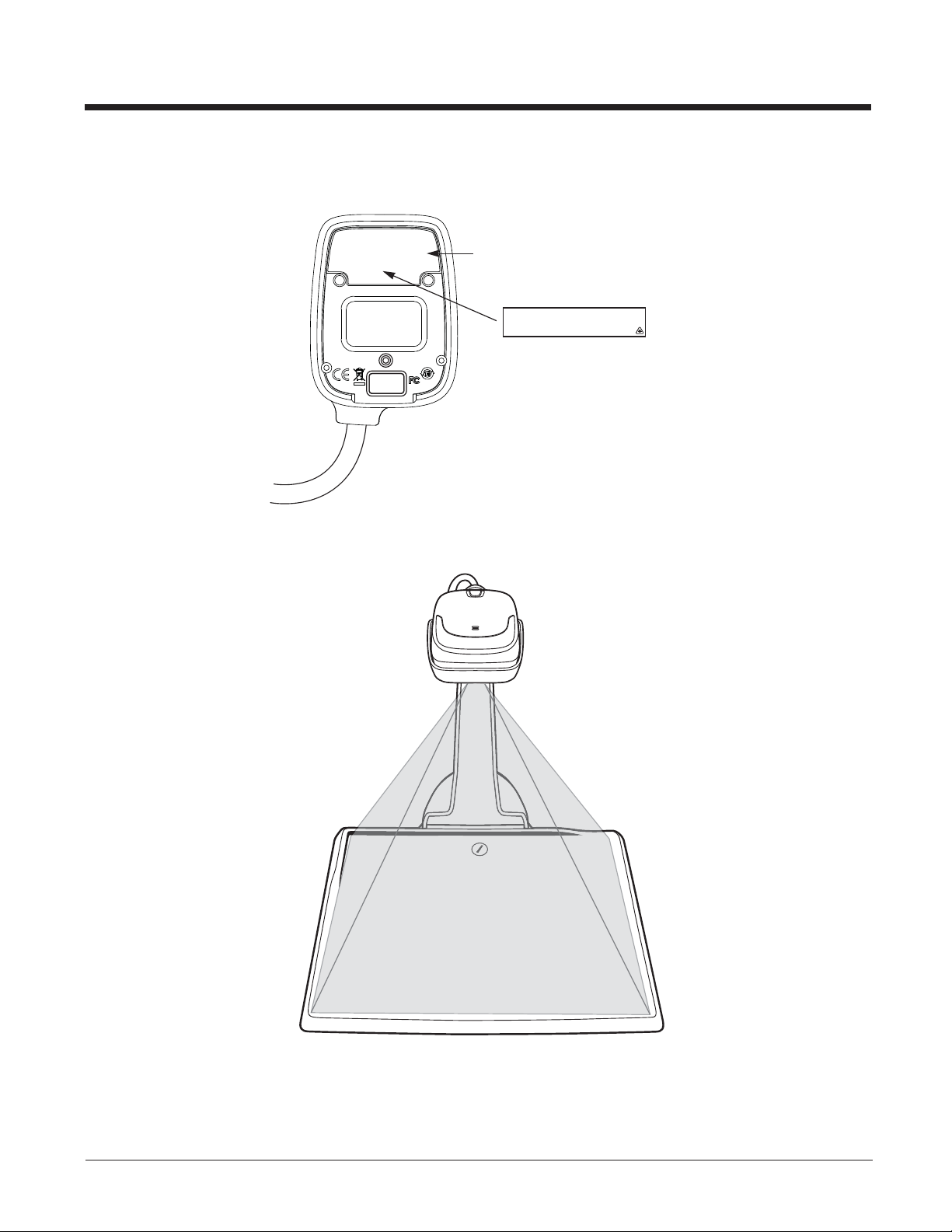
Document Reader Identification
Compliance
Label location
LASER LIGHT - DO NOT STARE INTO BEAM. CLASS 2 LASER PRODUCT.
RAYONNEMENT LASER NE PAS REGARDER DANS LE FAISCEAU. APPAREIL À
LASER DE CLASSE 2. MAX. 1mW :630-680 nm. IEC 60825-1: 2007. Complies with
21 CFR 1040.10 and 1040.11 except for deviations pursuant To Laser Notice No. 50,
dated June 24, 2007.
Laser Light Emissions
Page 7

Table of Contents
Chapter 1 - Imaging Commands
Single-Use Basis................................................................................................................. 1-1
Command Syntax................................................................................................................ 1-1
Step 1 - Take a Picture Using IMGSNP .............................................................................. 1-1
Image Snap - IMGSNP ................................................................................................. 1-1
IMGSNP Modifiers ........................................................................................................ 1-1
Step 2 - Ship a Picture Using IMGSHP or IMGACP ........................................................... 1-4
Image Ship - IMGSHP................................................................................................... 1-4
Image Auto Crop - IMGACP.......................................................................................... 1-4
IMGSHP/IMGACP Modifiers ......................................................................................... 1-5
Intelligent Signature Capture - IMGBOX ........................................................................... 1-12
Signature Capture Optimize........................................................................................ 1-12
IMGBOX Modifiers ...................................................................................................... 1-13
Chapter 2 - Serial Default Commands
Conventions ........................................................................................................................ 2-1
Menu Command Syntax...................................................................................................... 2-1
Resetting the Custom Defaults ........................................................................................... 2-2
Menu Commands................................................................................................................ 2-3
Chapter 3 - Customer Support
Technical Assistance .......................................................................................................... 3-1
Product Service and Repair ................................................................................................ 3-1
i
Page 8

ii
Page 9

1
Imaging Commands
The document reader is like a digital camera in the way it captures, manipulates, and transfers images. The following commands allow you to alter the way the document reader performs these functions.
Single-Use Basis
Imaging Commands with their modifiers send instructions to the document reader on a single-use basis, and take effect for a
single image capture. Once that capture is complete, the document reader reverts to its imaging default settings. If you want to
permanently change a setting, you must use the serial default commands (see Chapter 2). When the serial default command is
used, that selection becomes the new, permanent setting for the document reader.
Command Syntax
Multiple modifiers and commands can be issued within one sequence. If additional modifiers are to be applied to the same
command, just add the modifiers to that command. For example, to add 2 modifiers to the Image Snap command, such as setting the Imaging Style to 1P and the Wait for Trigger to 1T, you would enter IMGSNP1P1T.
Note: After processing an image capture command (IMGSNP or IMGBOX), you must follow it with an IMGSHP or IMGACP
command if you want to see it on your terminal.
To add a command to a sequence, each new command is separated with a semicolon. For example, to add the Image Ship
command to the above sequence, you would enter IMGSNP1P1T;IMGSHP.
The imaging commands are:
Image Snap - IMGSNP (page 1-1)
Image Ship - IMGSHP (page 1-4)
Intelligent Signature Capture - IMGBOX (page 1-12)
The modifiers for each of these commands follow the command description.
Note: The images included with each command description are examples only. The results you achieve may be different from
those included in this manual. The quality of the output you receive will vary depending on lighting and the quality of the
initial image/object being captured.
Step 1 - Take a Picture Using IMGSNP
Image Snap - IMGSNP
An image is taken whenever the hardware button is pressed, or when the Image Snap (IMGSNP) command is processed.
The image snap command has many different modifiers that can be used to change the look of the image in memory. Any
number of modifiers may be appended to the IMGSNP command. For example, you can use the following command to
snap an image, increase the gain, and have the beeper sound once the snap is complete.
IMGSNP Modifiers
P - Imaging Style
This sets the Image Snap style.
0P Decoding Style. This processing allows a few frames to be taken until the exposure parameters are met. The last
frame is then available for further use.
1P Photo Style (default). This mimics a simple digital camera, and results in a visually optimized image.
2P Manual Style. This is an advanced style that should only be used by an experienced user. It allows you the most
freedom to set up the scanner, and has no auto-exposure.
B - Beeper
Causes a beep to sound after an image is snapped.
0B No beep (default)
1B Sounds a beep when the image is captured.
1-1
Page 10
T - Wait for Trigger
Waits for a hardware button push before taking the image. This is only available when using Photo Style (1P).
0T Takes image immediately (default)
1T Waits for a button push, then takes the image
L - LED State
Determines if the LEDs should be on or off, and when. Ambient illumination (0L) is preferred for taking pictures of color
documents, such as ID cards, especially when the scanner is in a stand. LED illumination (1L) is preferred when the scanner is handheld. LED State is not available when using Decoding Style (0P).
0L LEDs off (default)
1L LEDs on
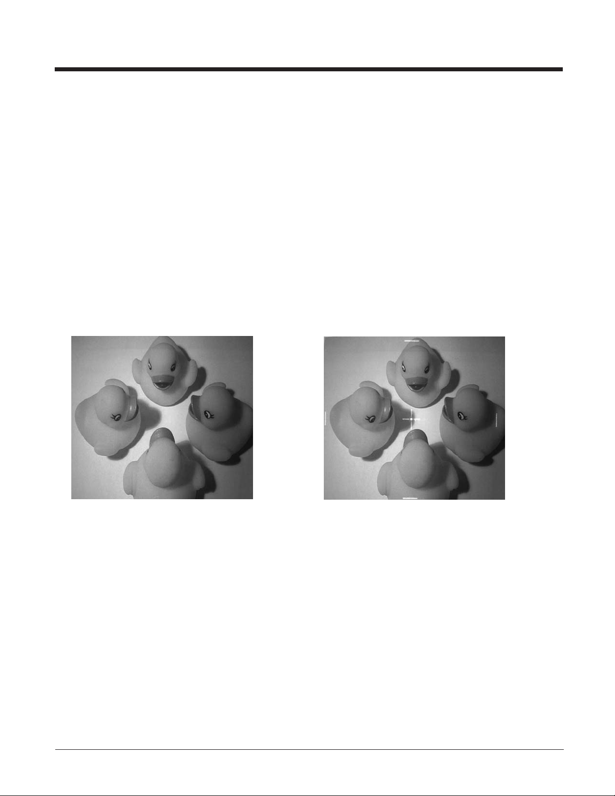
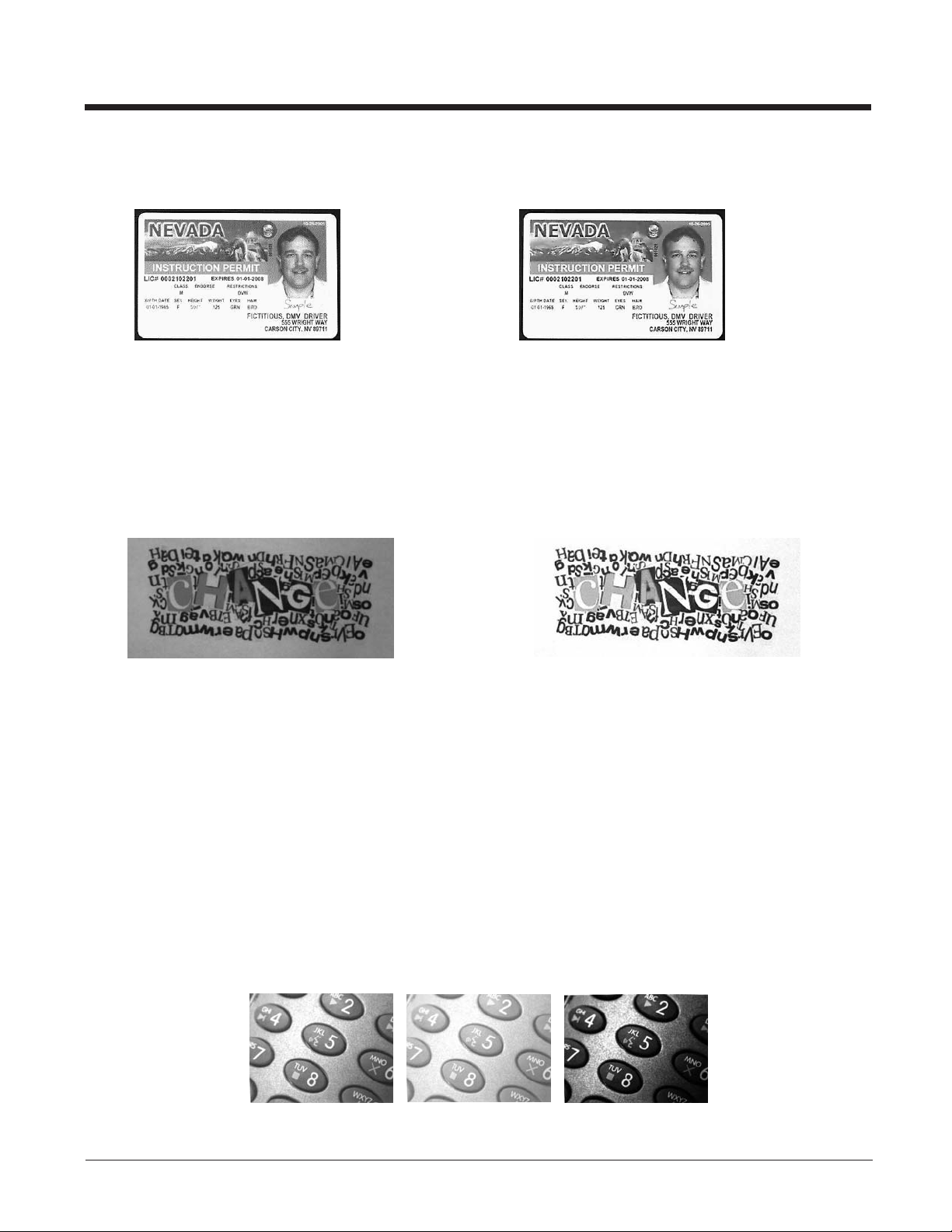
A - Aimer Lines
Sets whether the aimer lines will be captured with the image or not. In order to capture the aimer lines, the LEDs must also
be off. If the LEDs are on, the aimer lines will not be captured.
0A Aimer Lines off (default)
1A Aimer Lines on
Example of Aimer Lines Off (0A): Example of Aimer Lines On (1A) with LEDs off
E - Exposure
Exposure is used in Manual Style only (2P), and allows you to set the exposure time. This is similar to setting a shutter
speed on a camera. The exposure time determines how long the scanner takes to record an image. On a bright day, exposure times can be very short because plenty of light is available to help record an image. At nighttime, exposure time can
increase dramatically due to the near absence of light. Units are 127 microseconds. (Default = 7874)
(0L):
1-2
Page 11
nE Range: 1 - 7874
Example of Exposure at 7874E with
fluorescent lighting:
G - Gain
Gain is used in Manual Style only (2P). Like a volume control, the gain modifier boosts the signal and multiplies the pixel
value. As you increase the gain, the noise in an image is also amplified.
1G No gain (default)
2G Medium gain
4G Heavy gain
8G Maximum gain
Example of Gain at
1G:
Example of Gain at
4G:
Example of Exposure at 100E with
fluorescent lighting:
Example of Gain at
8G:
W - Target White Value
Sets the target for the median grayscale value in the captured image. For capturing close-up images of high contrast documents, a lower setting, such as 75, is recommended. Higher settings result in longer exposure times and brighter images,
but if the setting is too high, the image may be overexposed. Target White Value is only available when using Photo Style
(1P). (Default = 125)
nW Range:0-255
Example of White
Value at 75W:
D - Delta for Acceptance
This sets the allowable range for the white value setting (see W - Target White Value). Delta is only available when using
Photo Style (1P). (Default = 25)
nD Range: 0 - 255
U - Update Tries
This sets the maximum number of frames the scanner should take to reach the D - Delta for Acceptance. Update Tries is
only available when using Photo Style (1P). (Default = 6)
nU Range: 0 - 10
Example of White
Value at 125W:
Example of White
Value at 200W:
1-3
Page 12

% - Target Set Point Percentage
Sets the target point for the light and dark values in the captured image. A setting of 75% means 75% of the pixels are at or
below the target white value, and 25% of the pixels are above the target white value. Altering this setting from the default is
not recommended under normal circumstances. To alter grayscale values, W - Target White Value should be used.
(Default = 50)
n% Range:1-99
Example of Target
Set Point
Percentage at 97%:
Example of Target
Set Point
Percentage at 50%:
Example of Target
Set Point
Percentage at 40%:
Step 2 - Ship a Picture Using IMGSHP or IMGACP
Image Ship - IMGSHP
An image is taken whenever the button is pressed, or when the Image Snap (IMGSNP) command is processed. The last
image is always stored in memory. You can “ship” the image by using the IMGSHP or IMGACP command.
The image ship and image auto crop commands have many different modifiers that can be used to change the look of the
image output by the document reader. Modifiers affect the image that is transmitted, but do not affect the image in memory.
Modifiers always begin with a number and end with a letter (case insensitive). Any number of modifiers may be appended
to the IMGSHP or IMGACP command. For example, you can use the following command to snap and ship a bitmap image
with gamma correction and document image filtering:
IMGSNP;IMGSHP8F75K26U
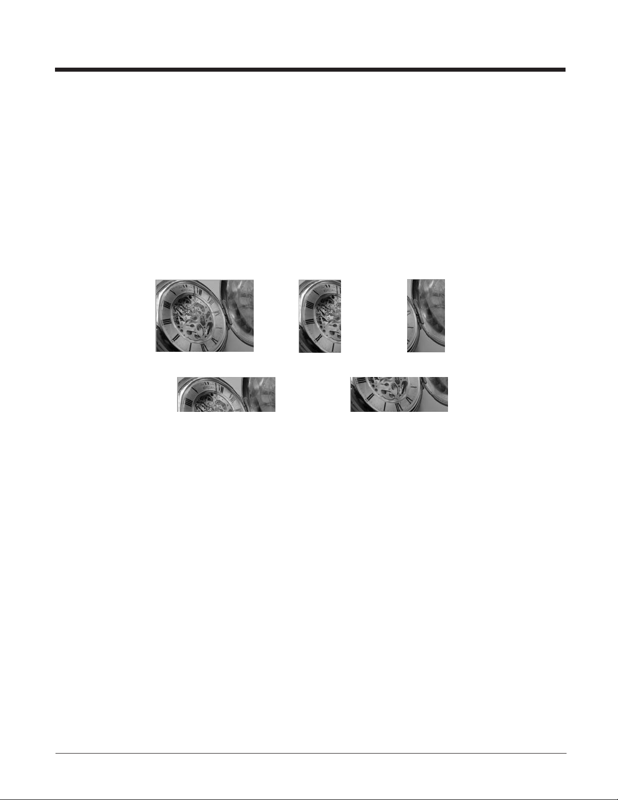
Image Auto Crop - IMGACP
Image Auto Crop removes unwanted portions of an image, such as blank space surrounding an image. Image Auto Crop
uses artificial intelligence to search for the area of the image that contains text. It then crops the image to just that area and
adjusts it to a horizontal display. Depending on the size and position of the document, this may possibly result in an upsidedown or sideways image. The image can then be rotated to the proper orientation using your local software. Smaller documents will crop more quickly than larger documents. The accuracy of auto crop is affected by the density of the text,
amount of non-text features, and contrast in the image.
Note: Any modifiers to IMGACP are applied to the resultant, auto cropped image.
The same modifiers are used for image ship and image auto crop. The following command was used to take and crop an
image that had the white value lowered and the edge sharpen filter on:
IMGSNP75W;IMGACP14E
1-4
Page 13
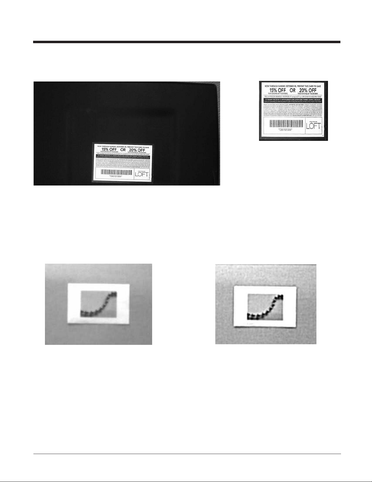
Image taken without Autocrop: Image taken with Autocrop:
IMGSHP/IMGACP Modifiers
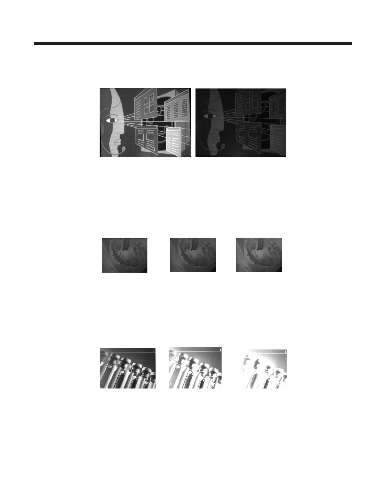
A - Infinity Filter
Enhances pictures taken from very long distances (greater than 10 feet or 3m). The Infinity Filter should not be used with
Image Auto Crop - IMGACP (page 1-4).
0A Infinity filter off (default)
1A Infinity filter on
Example of Infinity Filter off (0A)
from approximately 12 feet (3.66m) away:
Example of Infinity Filter on (1A)
from approximately 12 feet (3.66m) away:
1-5
Page 14
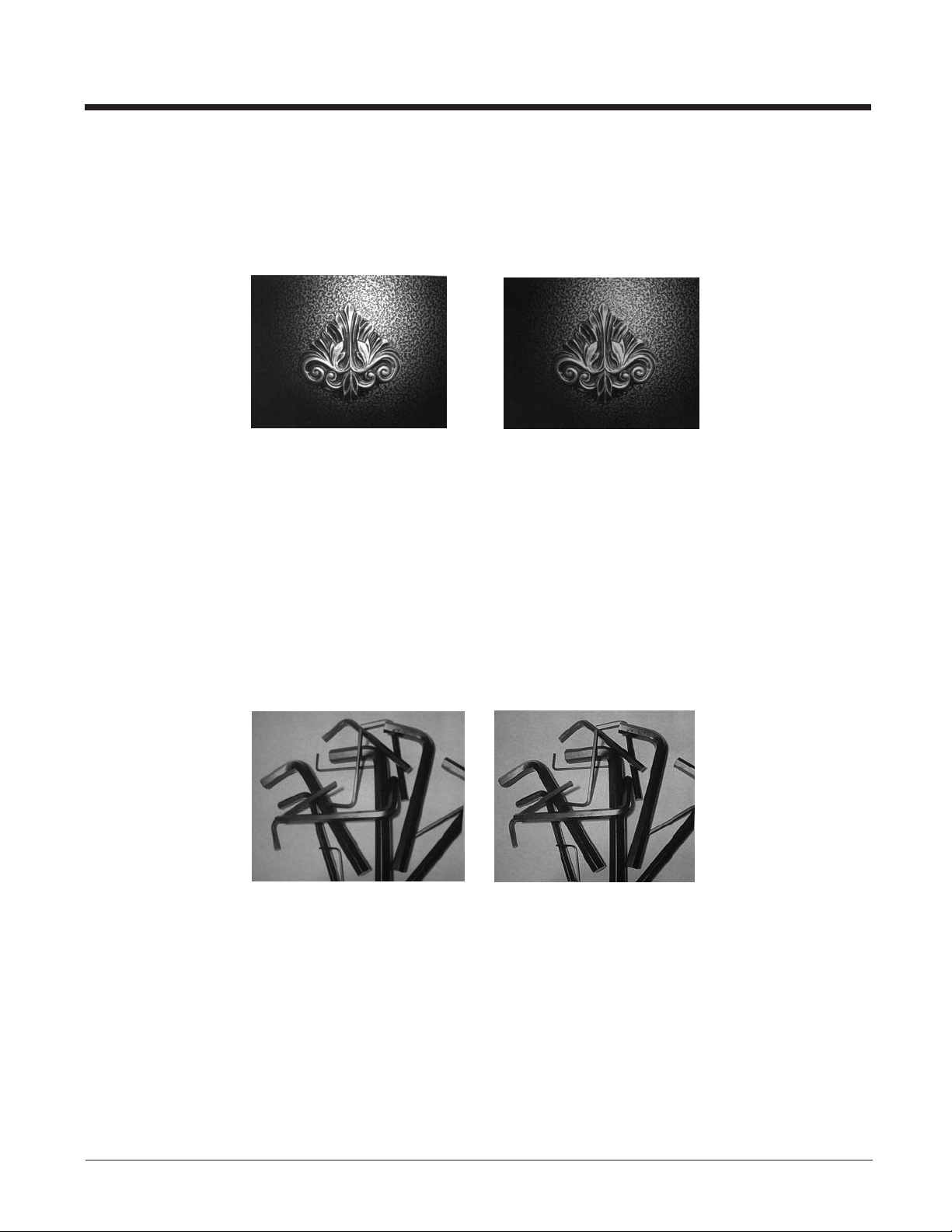
C - Compensation
Flattens the image to account for variations in illumination across the image.
0C Compensation disabled (default)
1C Compensation enabled
Example of Compensation at 0C: Example of Compensation at 1C:
D - Pixel Depth
Indicates the number of bits per pixel in the transmitted image (KIM or BMP format only).
8D 8 bits per pixel, grayscale image (default)
1D 1 bit per pixel, black and white image
E - Edge Sharpen
An edge sharpen filter cleans up the edges of an image, making it look cleaner and sharper. While edge sharpening does
make the image look cleaner, it also removes some fine detail from the original image. The strength of the edge sharpen
filter can be entered from 1 to 24. Entering a 23E gives the sharpest edges, but also increases noise in the image.
0E Don’t sharpen image (default)
14E Apply edge sharpen for typical image
ne Apply edge sharpen using strength n (n = 1-24)
Example of Edge Sharpen at 0E: Example of Edge Sharpen at 24E:
F - File Format
Indicates the desired format for the image.
0F KIM format
1F TIFF binary
2F TIFF binary group 4, compressed
3F TIFF grayscale
4F Uncompressed binary (upper left to lower right, 1 pixel/bit, 0 padded end of line)
5F Uncompressed grayscale (upper left to lower right, bitmap format)
6F JPEG image (default)
8F BMP format (lower right to upper left, uncompressed)
1-6
Page 15
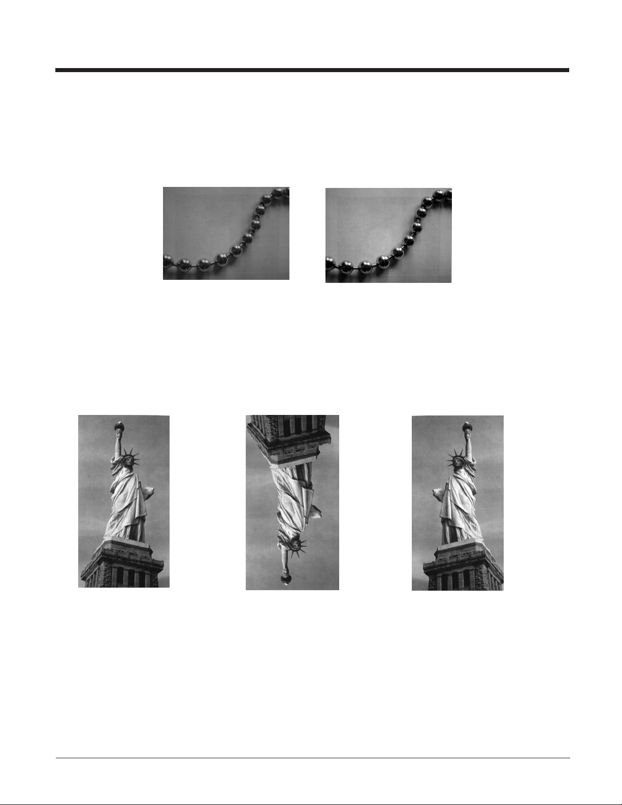
H - Histogram Stretch
Increases the contrast of the transmitted image. Not available with some image formats.
0H No stretch (default)
1H Histogram stretch
Example of Histogram Stretch at 0H: Example of Histogram Stretch at 1H:
I - Invert Image
Invert image is used to rotate the image around the X or Y axis.
Note: This feature should only be used with Image Ship - IMGSHP (page 1-4). Using this feature with Image Auto Crop
- IMGACP (page 1-4) may produce undesired results since Image Auto Crop attempts to rotate an image to a
horizontal display.
1ix Invert around the X axis (flips picture upside down)
1iy Invert around the Y axis (flips picture left to right)
Example of image not
inverted:
IF- Noise Reduction
Used to reduce the salt and pepper noise in an image.
0if No salt and pepper noise reduction (default)
Example of image
with Invert Image set to 1ix:
Example of image
with Invert Image set to 1iy:
1-7
Page 16
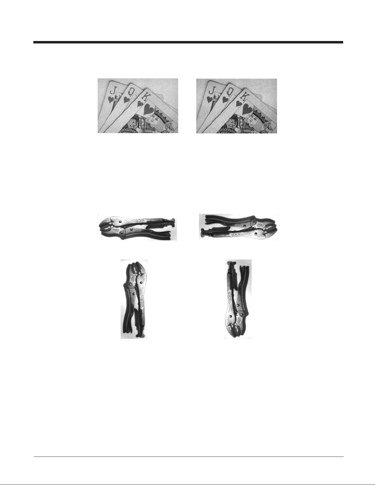
1if Salt and pepper noise reduction
Example of Noise Reduction On (1if):Example of Noise Reduction Off (0if):
IR - Image Rotate
Note: This feature should only be used with Image Ship - IMGSHP (page 1-4). Using this feature with Image Auto Crop -
IMGACP (page 1-4) may produce undesired results since Image Auto Crop attempts to rotate an image to a
horizontal display.
0ir Image as snapped (rightside up) (default)
1ir Rotate image 90 degrees to the right
2ir Rotate image 180 degrees (upside down)
3ir Rotate image 90 degrees to the left
Example of Image Rotate set to 0ir:
Example of Image Rotate set to 2ir:
Example of Image Rotate set to 1ir: Example of Image Rotate set to 3ir:
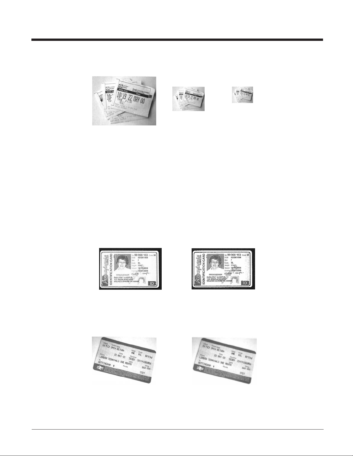
IU - Image Adaptive Text Filter
The Adaptive Text Filter automatically sharpens the edges and smooths the area between the edges of text in an image.
The Adaptive Text Filter enhances images of documents such as ID cards and prescriptions, resulting in crisper text.
See U - Document Image Filter (page 1-11) for information about setting the Document Image Filter manually.
Note: The Adaptive Text Filter should not be used concurrently with the IS - Unsharp/Brighten Filter.
0iu Adaptive Text Filter off (default)
1-8
Page 17
1iu Adaptive Text Filter on
Example of Adaptive Text Filter On (1iu):Example of Adaptive Text Filter Off (0iu):
IS - Unsharp/Brighten Filter
The Unsharp/Brighten Filter automatically sharpens the text and brightens the contrast of the image, making text more
readable. This is similar to the Image Adaptive Text Filter, however it brightens the image as well. You should test both
image processing techniques to determine which filter works best for your environment.
Note: The Unsharp/Brighten Filter should not be used concurrently with the IU - Image Adaptive Text Filter.
0is Unsharp/Brighten Filter off (default)
1is Unsharp/Brighten Filter on
Example of Unsharp/Brighten Filter Off (0is): Example of Unsharp/Brighten Filter On (1is):
J - JPEG Image Quality
Sets the desired quality when the JPEG image format is selected. Higher numbers result in higher quality, but larger files.
Smaller numbers result in greater amounts of lossy compression, faster transmission times, lower quality, but smaller files.
(Default = 50)
nJ Image is compressed as much as possible while preserving quality factor of n (n = 0 - 100)
0J worst quality (smallest file)
100Jbest quality (largest file)
K - Gamma Correction
Gamma measures the brightness of midtone values produced by the image. You can brighten or darken an image using
gamma correction. A higher gamma correction yields an overall brighter image. The lower the setting, the darker the
image. The optimal setting for text images is 50K.
0K Gamma correction off (default)
50K Apply gamma correction for brightening typical document image
nK Apply gamma correction factor n (n = 0-1,000)
Example of Gamma
Correction set to 0K:
Example of Gamma
Correction set to 50K:
Example of Gamma
Correction set to 255K:
1-9
Page 18
L, R, T, B, M - Image Cropping
Note: Image Cropping should not be used with Image Auto Crop - IMGACP (see page 1-4).
Ships a window of the image by specifying the left, right, top, and bottom pixel coordinates. Device columns are numbered
0 through 1279, and device rows are numbered 0 through 959.
nL The left edge of the shipped image corresponds to column n of the image in memory. Range: 000 - 2591. (Default
=0)
nR The right edge of the shipped image corresponds to column n - 1 of the image in memory. Range: 000 - 2591.
(Default = all columns)
nT The top edge of the shipped image corresponds to row n of the image in memory. Range: 000 - 1943. (Default = 0)
nB The bottom edge of the shipped image corresponds to row n - 1 of the image in memory. Range: 000 - 1943.
(Default = all rows)
Uncropped Image:
Alternately, specify the number of pixels to cut from the outside margin of the image; thus only the center pixels are transmitted.
nMMargin: cut n columns from the left, n + 1 columns from the right, n rows from the top, and n + 1 rows from the bottom
of the image. Ship the remaining center pixels. Range: 0 - 970.
P - Protocol
Used for shipping an image. Protocol covers two features of the image data being sent to the host. It addresses the protocol used to send the data (Hmodem, which is an Xmodem 1K variant that has additional header information), and the format of the image data that is sent.
0P None (raw data)
2P None (default for USB)
3P Hmodem compressed (default for RS232)
4P Hmodem
S - Pixel Ship
Pixel Ship sizes an image in proportion to its original size. It decimates the image by shipping only certain, regularly
spaced pixels. For example, 4S would transmit every fourth pixel from every fourth line. The smaller number of pixels
shipped, the smaller the image, however, after a certain point the image becomes unusable.
1S ship every pixel (default)
2S ship every 2nd pixel, both horizontally and vertically
Example of Image Crop
set to 300R:
Example of Image Crop set to 200T:Example of Image Crop set to 200B:
Example of Image
Crop set to 300L:
1-10
Page 19
3S ship every 3rd pixel, both horizontally and vertically
Example of Pixel Ship set to 1S:
U - Document Image Filter
Allows you to input parameters to sharpen the edges and smooth the area between the edges of text in an image. This filter should be used with gamma correction (see page 1-9), with the scanner in a stand, and the image captured using the
command:
Example of Pixel
Ship set to 2S:
Example of Pixel
Ship set to 3S:
IMGSNP1P0L168W90%32D
This filter typically provides better JPEG compression than the standard E - Edge Sharpen command (see page 1-11).
This filter also works well when shipping pure black and white images (1 bit per pixel). The optimal setting is 26U.
Note: If you want to use an automatic image filter, rather than changing these settings manually, refer to IU - Image Adaptive
Text Filter (page 1-8).
0U Document image filter off (default)
26U Apply document image filter for typical document image
nU Apply document image filter using grayscale threshold n. Use lower numbers when the image contrast is lower.
1U will have a similar effect to setting E - Edge Sharpen (page 1-6) to 22e. Range: 0-255.
Example of Document
Image Filter set to 0U:
V - Blur Image
Smooths transitions by averaging the pixels next to the hard edges of defined lines and shaded areas in an image.
0V Don’t blur (default)
1V Blur
Example of Blur Image Off (0V): Example of Blur Image On (1V):
W - Histogram Ship
A histogram gives a quick picture of the tonal range of an image, or key type. A low-key image has detail concentrated in
the shadows; a high-key image has detail concentrated in the highlights; and an average-key image has detail concentrated
in the midtones. This modifier ships the histogram for an image.
Example of Document
Image Filter set to 26U:
1-11
Page 20

0W Don’t ship histogram (default)
1W Ship histogram
Image used for histogram: Histogram of image at left:
Intelligent Signature Capture - IMGBOX
IMGBOX allows you to configure the size and location of a signature capture area relative to its proximity to a bar code. This
allows you to tailor a signature capture area to a specific form. In order to use IMGBOX, you need a set form where the signature box location is in a known location relative to a bar code. You can input the overall size of the signature area, as well as
specify how far the signature area is from the bar code, vertically and horizontally. You can also set the resolution and file format
for the final output of the signature capture image.
Note: IMGBOX commands can only be triggered by one of the following types of bar codes: PDF417, Code 39, Code 128, Aztec,
Codabar, and Interleaved 2 of 5. Once one of these symbologies has been read, the image is retained for a possible
IMGBOX command.
Signature Capture Optimize
If you will be using your scanner to capture signatures frequently, you should optimize it for this purpose. However, the
speed of scanning bar codes may be slowed when this mode is enabled. Default = Off.
Optimize On
* Optimize Off
The following IMGBOX example was executed and viewed using QuickView software. This software is available at
www.honeywellaidc.com. Click on Software Downloads. Select 4600r from the Products list, then select QuickView Soft-
ware Utility.
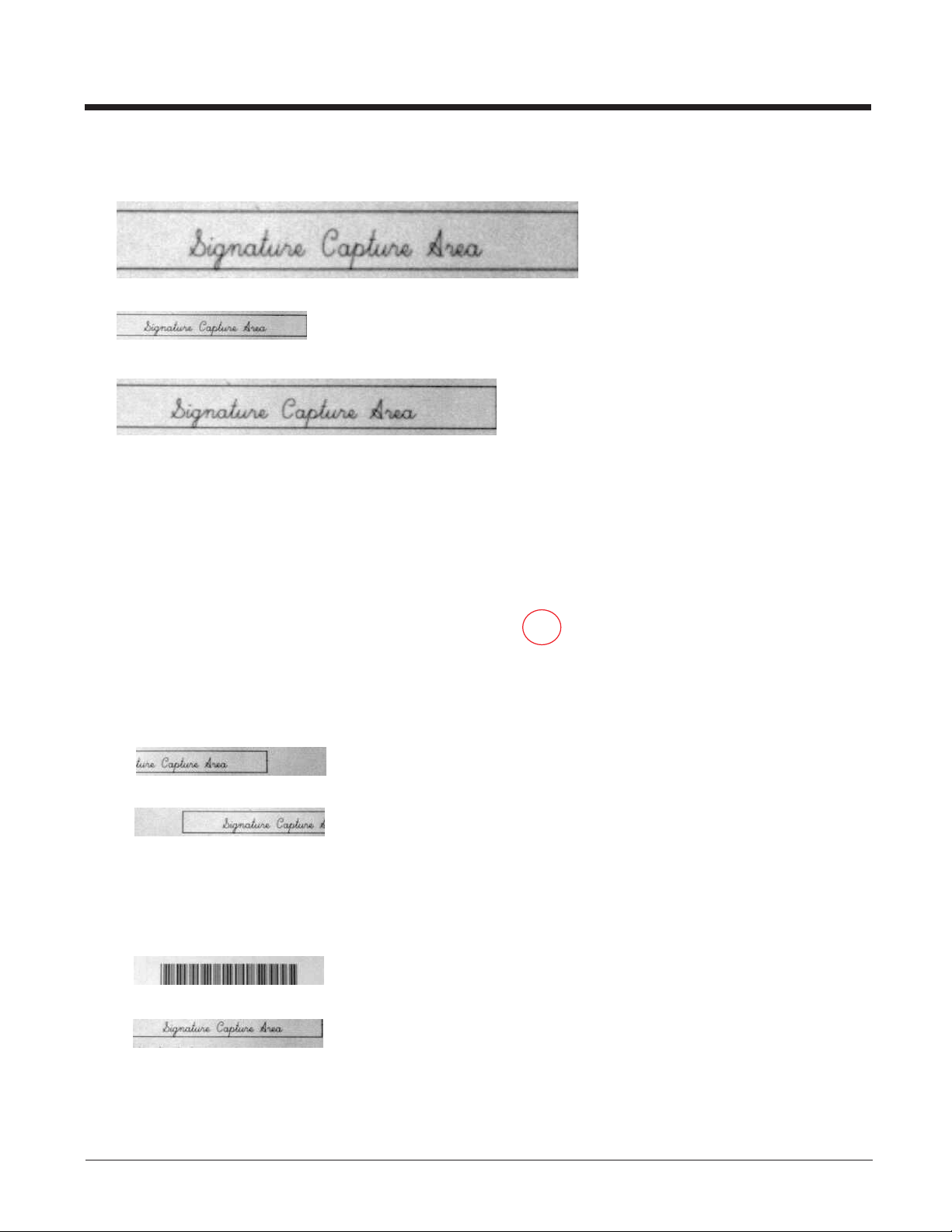
Below is an example of a signature capture application. In this example, the aimer is centered over the signature capture area
and the trigger is pressed. A single beep is emitted, indicating that the scanner has read a Code 128 bar code and the data has
been transferred to the host. If using a Granit scanner, the scanner also vibrates. An IMGBOX command may now be sent
from the host to specify the coordinates of the signature capture area below that code, and indicating that only that area containing the signature should be transferred as an image to the host.
1-12
Page 21

To see this example, align the aimer with the signature area (not with the bar code), then press the trigger.
Send the following IMGBOX command string after the button push:
Example: IMGBOX245w37h55y.
Note: Case is not important in the command string. It is used here only for clarity.
The following image is captured:
The IMGBOX commands have many different modifiers that can be used to change the size and appearance of the signature
image output by the scanner. Modifiers affect the image that is transmitted, but do not affect the image in memory. Any number
of modifiers may be appended to the IMGBOX command.
Note: The IMGBOX command will return a NAK unless a window size (width and height) are specified. See H - Height of
Signature Capture Area (page 1-14) and W - Width of Signature Capture Area (page 1-15).
IMGBOX Modifiers
A - Output Image Width
This option is used to size the image horizontally. If using this option, set the resolution (R) to zero.
Example of Image Width set to 200A:
Example of Image Width set to 600A:
B - Output Image Height
This option is used to size the image vertically. If using this option, set the resolution (R) to zero.
Example of Image Height set to 50B:
Example of Image Height set to 100B:
D - Pixel Depth
This indicates the number of bits per pixel in the transmitted image, which defines whether it will be grayscale or black and
white.
8D 8 bits per pixel, grayscale image (default)
1-13
Page 22

1D 1 bit per pixel, black and white image
F - File Format
This option indicates the type of file format in which to save the image.
0F KIM format
1F TIFF binary
2F TIFF binary group 4, compressed
3F TIFF grayscale
4F Uncompressed Binary
5F Uncompressed grayscale
6F JPEG image (default)
7F Outlined image
8F BMP format
H - Height of Signature Capture Area
The height of the signature capture area must be measured in inches divided by .01. In the example, the height of the area
to be captured is 3/8 inch, resulting in a value of H = .375/0.01 = 37.5.
Example: IMGBOX245w37h55y.
K - Gamma Correction
Gamma measures the brightness of midtone values produced by the image. You can brighten or darken an image using
gamma correction. A higher gamma correction yields an overall brighter image. The lower the setting, the darker the
image. The optimal setting for text images is 50K.
0K Gamma correction off (default)
50K Apply gamma correction for brightening typical document image
nK Apply gamma correction factor n (n = 1-255)
Example of Gamma
Correction set to 0K:
Example of Gamma Correction
set to 50K:
Example of Gamma Correction
set to 255K:
R - Resolution of Signature Capture Area
The resolution is the number of pixels that the scanner outputs per each minimum bar width. The higher the value for R,
the higher the quality of the image, but also the larger the file size. Values begin at 1000. The scanner automatically
inserts a decimal point between the first and second digit. For example, use 2500 to specify a resolution of 2.5. Set to zero
1-14
Page 23
when using the A and B modifiers (see A - Output Image Width and B - Output Image Height on page 1-13).
Example of Resolution set to 0R:
Example of Resolution set to 1000R:
Example of Resolution set to 2000R:
S - Bar Code Aspect Ratio
All dimensions used in IMGBOX are measured as multiples of the minimum element size of the bar code. The bar code
aspect ratio allows you to set the ratio of the bar code height to the narrow element width. In the example, the narrow element width is .010 inches and the bar code height is 0.400 inches, resulting in a value of S = 0.4/0.01 = 40.
W - Width of Signature Capture Area
The width of the signature capture area must be measured in inches divided by .01. In the example, the width of the area
to be captured is 2.4 inches, resulting in a value of W = 2.4/0.01 = 240. (A value of 245 was used in the example to accommodate a slightly wider image area.)
Example: IMGBOX245w37h55y.
X - Horizontal Bar Code Offset
The horizontal bar code offset allows you to offset the horizontal center of the signature capture area. Positive values move
the horizontal center to the right and negative values to the left. Measurements are in multiples of the minimum bar width.
Example of Horizontal Offset set to 75X:
Example of Horizontal Offset set to -75X:
Y - Vertical Bar Code Offset
The vertical bar code offset allows you to offset the vertical center of the signature capture area. Negative numbers indicate that the signature capture is above the bar code, and positive numbers indicate that the area is below the bar code.
Measurements are in multiples of the minimum bar width.
Example of Vertical Offset set to -7Y:
Example of Vertical Offset set to 65Y:
1-15
Page 24

1-16
Page 25

2
Serial Default Commands
The following serial default commands are used to program the imaging features for your document reader. For complete
descriptions of each command, refer to the corresponding page in this manual. For non-imaging programming commands, refer
to the Bar Code Manual.
The following commands can be sent via a PC COM port using terminal emulation software.
Conventions
The following conventions are used for menu and query command descriptions:
parameter A label representing the actual value you should send as part of a command.
[option] An optional part of a command.
{Data} Alternatives in a command.
bold Names of menus, menu commands, buttons, dialog boxes, and windows that appear on the screen.
Menu Command Syntax
Menu commands have the following syntax (spaces have been used for clarity only):
Prefix Tag SubTag {Data} [, SubTag {Data}] [; Tag SubTag {Data}] […] Storage
Prefix Three ASCII characters: SYNMCR (ASCII 22,77,13).
Tag A 3 character case-insensitive field that identifies the desired menu command group. For example, all RS-232
configuration settings are identified with a Tag of 232.
SubTag A 3 character case-insensitive field that identifies the desired menu command within the tag group. For example, the
SubTag for the RS-232 baud rate is BAD.
Data The new value for a menu setting, identified by the Tag and SubTag.
Storage A single character that specifies the storage table to which the command is applied. An exclamation point (!) performs
the command’s operation on the device’s volatile menu configuration table. A period (.) performs the command’s
operation on the device’s non-volatile menu configuration table. Use the non-volatile table only for semi-permanent
changes you want saved through a power cycle.
Query Commands
Several special characters can be used to query the device about its settings.
^ What is the default value for the setting(s).
? What is the device’s current value for the setting(s).
* What is the range of possible values for the setting(s). (The device’s response uses a dash (-) to indicate a
continuous range of values. A pipe (|) separates items in a list of non-continuous values.)
:Name: Field Usage (Optional)
This command returns the query information from the scanner.
Tag Field Usage
When a query is used in place of a Tag field, the query applies to the entire set of commands available for the particular
storage table indicated by the Storage field of the command. In this case, the SubTag and Data fields should not be used
because they are ignored by the device.
SubTag Field Usage
When a query is used in place of a SubTag field, the query applies only to the subset of commands available that match the
Tag field. In this case, the Data field should not be used because it is ignored by the device.
2-1
Page 26

Data Field Usage
When a query is used in place of the Data field, the query applies only to the specific command identified by the Tag and
SubTag fields.
Concatenation of Multiple Commands
Multiple commands can be issued within one Prefix/Storage sequence. Only the Tag, SubTag, and Data fields must be
repeated for each command in the sequence. If additional commands are to be applied to the same Tag, then the new
command sequence is separated with a comma (,) and only the SubTag and Data fields of the additional command are
issued. If the additional command requires a different Tag field, the command is separated from previous commands by a
semicolon (;).
Responses
The device responds to serial commands with one of three responses:
ACK Indicates a good command which has been processed.
ENQ Indicates an invalid Tag or SubTag command.
NAK Indicates the command was good, but the Data field entry was out of the allowable range for this Tag and SubTag
combination, e.g., an entry for a minimum message length of 100 when the field will only accept 2 characters.
When responding, the device echoes back the command sequence with the status character inserted directly before
each of the punctuation mar ks (the period, exclamation point, comma, or semicolon) in the command.
Examples of Quer y Commands
In the following examples, a bracketed notation [ ] depicts a non-displayable response.
Example: What is the range of possible values for Imaging Style?
Enter: snpsty*.
Response: SNPSTY0-2[ACK]
This response indicates that Imaging Style (SNPSTY) has a range of values from 0 to 2.
Example: What is the default value for Imaging Style?
Enter: snpsty^.
Response: SNPSTY1[ACK]
This response indicates that the default setting for Imaging Style (SNPSTY) is 1, or Photo.
Example: What is the device’s current setting for Imaging Style?
Enter: snpsty?.
Response: SNPSTY2[ACK]
This response indicates that the device’s Imaging Style (SNPSTY) is set to 2, or Manual.
Resetting the Custom Defaults
If you want the custom default settings restored to your scanner, scan the Activate Custom Defaults bar code below. This
resets the scanner to the custom default settings. If there are no custom defaults, it will reset the scanner to the factory default
settings. Any settings that have not been specified through the custom defaults will be defaulted to the factory default settings.
Activate Custom Defaults
The charts on the following pages list the factory default settings for each of the commands (indicated by an asterisk (*) on the
programming pages).
2-2
Page 27

Menu Commands
The following chart lists the settings for each of the serial default commands. The factory default setting is indicated by an asterisk (*).
Selection
Setting
* Indicates default
Imaging Default Commands
Default all Imaging Commands
Image Snap
Imaging Style - Decoding
(IMGSNP)
*Imaging Style - Photo
Imaging Style - Manual
Beeper On
*Beeper Off
*Wait for Trigger Off
Wait for Trigger On
*LED State - Off
LED State - On
Aimer Lines On
*Aimer Lines Off
Exposure (1-7874 microseconds)
Gain - None
Gain - Medium
Gain - Heavy
*Gain - Maximum
Target White Value (0-255) *125
Delta for Acceptance (0-255) *25
Update Tries (0-10) *6
Target Set Point Percentage (1-99) *97
Image Ship
(IMGSHP) and
Image Auto Crop
*Infinity Filter - Off IMGINF0
(IMGACP)
Infinity Filter - On
*Compensation Off
Compensation On
*Pixel Depth - 8 bits/pixel (grayscale)
Pixel Depth - 1 bit/pixel (B&W)
*Don’t Sharpen Edges
Sharpen Edges (0-23)
*File Format - JPEG
File Format - KIM
File Format - TIFF binar y
File Format - TIFF binar y group 4, compressed
File Format - TIFF grayscale
File Format - Uncompressed binary
Serial Command
# Indicates a numeric entry
IMGDFT
SNPSTY0
SNPSTY1
SNPSTY2
SNPBEP1
SNPBEP0
SNPTRG0
SNPTRG1
SNPLED0
SNPLED1
SNPAIM1
SNPAIM0
SNPEXP
SNPGAN1
SNPGAN2
SNPGAN4
SNPGAN8
SNPWHT###
SNPDEL###
SNPTRY##
SNPPCT##
IMGINF1
IMGCOR0
IMGCOR1
IMGBPP8
IMGBPP1
IMGEDG0
IMGEDG##
IMGFMT6
IMGFMT0
IMGFMT1
IMGFMT2
IMGFMT3
IMGFMT4
For full description,
see page
1-1
1-1
1-1
1-1
1-1
1-2
1-2
1-2
1-2
1-2
1-2
1-2
1-3
1-3
1-3
1-3
1-3
1-3
1-3
1-3
1-5
1-5
1-6
1-6
1-6
1-6
1-6
1-6
1-6
1-6
1-6
1-6
1-6
1-6
2-3
Page 28

Selection
Setting
* Indicates default
File Format - Uncompressed grayscale
File Format - BMP
*Histogram Stretch Off
Histogram Stretch On
Invert Image around X axis
Invert Image around Y axis
*Noise Reduction Off
Noise Reduction On
*Rotate Image Off
Rotate Image 90° right
Rotate Image 180°
Rotate Image 90° left
*Adaptive Text Filter Off
Adaptive Text Filter On
*Unsharp/Brighten Filter Off
Unsharp/Brighten Filter On
JPEG Image Quality (0-100) *50
*Gamma Correction Off
Gamma Correction On (0-1,000)
Image Crop - Left (0-2591) *0
Image Crop - Right (0-2591) *1279
Image Crop - Top (0-1943) *0
Image Crop - Bottom (0-1943) *1943
Image Crop - Margin (0-970) *0
Protocol - None (raw)
Protocol - None (default USB)
Protocol - Hmodem
Protocol - Hmodem Compressed
*Ship Every Pixel
Ship Every 2nd Pixel
Ship Every 3rd Pixel
*Document Image Filter Off
Document Image Filter On (0-255)
*Blur Image Off
Blur Image On
*Don’t Ship Histogram
Ship Histogram
Serial Command
# Indicates a numeric entry
IMGFMT5
IMGFMT8
IMGHIS0
IMGHIS1
IMGNVX1
IMGNVY1
IMGFSP0
IMGFSP1
IMGROT0
IMGROT1
IMGROT2
IMGROT3
IMGAUT0
IMGAUT1
IMGSNZ0
IMGSNZ1
IMGJQF###
IMGGAM0
IMGGAM###
IMGWNL###
IMGWNR###
IMGWNT###
IMGWNB###
IMGMAR###
IMGXFR0
IMGXFR2
IMGXFR3
IMGXFR4
IMGSUB1
IMGSUB2
IMGSUB3
IMGUSH0
IMGUSH###
no serial command
no serial command
IMGHST0
IMGHST1
For full description,
see page
1-6
1-6
1-7
1-7
1-7
1-7
1-7
1-7
1-8
1-8
1-8
1-8
1-8
1-8
1-9
1-9
1-9
1-9
1-9
1-10
1-10
1-10
1-10
1-10
1-10
1-10
1-10
1-10
1-10
1-10
1-10
1-11
1-11
1-11
1-11
1-11
1-11
2-4
Page 29

Selection
Intelligent
Signature Capture
(IMGBOX)
Setting
* Indicates default
Signature Capture Optimize On
*Signature Capture Optimize Off
Output Image Width
Output Image Height
*Pixel Depth - 8 bits/pixel (grayscale)
Pixel Depth - 1 bit/pixel (B&W)
*File Format - JPEG
File Format - KIM
File Format - TIFF binar y
File Format - TIFF binar y group 4, compressed
File Format - TIFF grayscale
File Format - Uncompressed binary
File Format - Uncompressed grayscale
File Format - BMP
Height of Signature Capture Area
*Gamma Correction Off
Gamma Correction On (1-255)
Resolution of Signature Capture Area (0-2500)
Bar Code Aspect Ratio
Width of Signature Capture Area
Horizontal Bar Code Offset
Vertical Bar Code Offset
Serial Command
# Indicates a numeric entry
DECBND1
DECBND0
no serial command
no serial command
IMGBPP8
IMGBPP1
IMGFMT6
IMGFMT0
IMGFMT1
IMGFMT2
IMGFMT3
IMGFMT4
IMGFMT5
IMGFMT8
no serial command
IMGGAM0
IMGGAM###
no serial command
no serial command
no serial command
no serial command
no serial command
For full description,
see page
1-12
1-12
1-13
1-13
1-13
1-13
1-14
1-14
1-14
1-14
1-14
1-14
1-14
1-14
1-14
1-14
1-14
1-14
1-15
1-15
1-15
1-15
2-5
Page 30

2-6
Page 31

3
Customer Support
Technical Assistance
If you need assistance installing or troubleshooting your device, please contact us by using one of the methods below:
Knowledge Base: www.hsmknowledgebase.com
Our Knowledge Base provides thousands of immediate solutions. If the Knowledge Base cannot help, our Technical Support
Portal (see below) provides an easy way to report your problem or ask your question.
Technical Suppor t Portal: www.hsmsupportportal.com
The Technical Support Portal not only allows you to report your problem, but it also provides immediate solutions to your techni-
cal issues by searching our Knowledge Base. With the Portal, you can submit and track your questions online and send and
receive attachments.
Web form: www.hsmcontactsupport.com
You can contact our technical support team directly by filling out our online support form. Enter your contact details and the
description of the question/problem.
Telephone: www.honeywellaidc.com/locations
For our latest contact information, please check our website at the link above.
Product Service and Repair
Honeywell International Inc. provides service for all of its products through service centers throughout the world. To obtain warranty or non-warranty service, please visit www.honeywellaidc.com and select Support > Contact Service and Repair to see
your region's instructions on how to obtain a Return Material Authorization number (RMA #). You should do this prior to returning the product.
3-1
Page 32

3-2
Page 33

Page 34

Honeywell Scanning & Mobility
9680 Old Bailes Road
Fort Mill, SC 29707
www.honeywellaidc.com
™
4850DR-IMG Rev B
3/14
 Loading...