

Page 1

4800dr
Document Reader
Barcode Guide
Page 2

Disclaimer
Honeywell International Inc. (“HII”) reserves the right to make changes in specifications and other information contained in this document without prior notice, and the reader should in all cases consult HII to
determine whether any such changes have been made. The information in this publication does not represent a commitment on the part of HII.
HII shall not be liable for technical or editorial errors or omissions contained herein; nor for incidental or
consequential damages resulting from the furnishing, performance, or use of this material.
This document contains proprietary information that is protected by copyright. All rights are reserved.
No part of this document may be photocopied, reproduced, or translated into another language without
the prior written consent of HII.
© 2007-2009 Honeywell International Inc. All rights reserved.
Other product names or marks mentioned in this document may be trademarks or registered trademarks
of other companies and are the property of their respective owners.
Web Address: www.honeywell.com/aidc
Microsoft
United States and/or other countries.
Macintosh
Other product names or marks mentioned in this document may be trademarks or registered trademarks
of other companies and are the property of their respective owners.
®
Windows® is either a registered trademark or trademarks of Microsoft Corporation in the
®
is a trademark of Apple Computer, Inc., registered in the U.S. and other countries.
Page 3

Table of Contents
Chapter 1 - Getting Started
About This Manual ...............................................................................................................1-1
Unpacking the Document Reader........................................................................................1-1
Document Reader Models ...................................................................................................1-1
Connecting the Document Reader with USB.......................................................................1-1
Connecting the Document Reader with TTL-232 Serial Port...............................................1-2
Supported Terminals............................................................................................................1-3
Programming the Interface - Plug and Play .........................................................................1-3
USB Connection ..................................................................................................................1-3
IBM SurePos..................................................................................................................1-3
USB PC or Macintosh
USB HID.........................................................................................................................1-4
USB COM Port Emulation..............................................................................................1-4
TTL-232 Serial Port Connection ..........................................................................................1-5
Aligning the Document Reader Tray....................................................................................1-5
Reading Techniques ............................................................................................................1-6
Using the Imager Out of the Stand.................................................................................1-6
®
Keyboard..................................................................................1-4
Chapter 2 - Terminal Interfaces
Keyboard Country ................................................................................................................2-1
Keyboard Style.....................................................................................................................2-2
Keyboard Modifiers ..............................................................................................................2-3
TTL-232 Baud Rate........................................................................................................2-4
RS-232 Word Length: Data Bits, Stop Bits, and Parity ..................................................2-5
TTL-232 Receiver Time-Out ..........................................................................................2-5
RS-232 Handshaking.....................................................................................................2-5
Chapter 3 - Output
Good Read Indicators ..........................................................................................................3-1
Beeper – Good Read .....................................................................................................3-1
Beeper Volume – Good Read........................................................................................3-1
Beeper Pitch – Good Read ............................................................................................3-1
Beeper Duration – Good Read.......................................................................................3-2
LED – Good Read..........................................................................................................3-2
LED – Indicator State.....................................................................................................3-2
Number of Beeps – Good Read.....................................................................................3-2
Good Read Delay ................................................................................................................3-3
User-Specified Good Read Delay........................................................................................3-3
Trigger Modes......................................................................................................................3-3
Manual/Serial Trigger.....................................................................................................3-3
Scan Stand Mode ................................................................................................................3-4
Scan Stand Symbol........................................................................................................3-4
Presentation Mode...............................................................................................................3-4
Presentation Sensitivity..................................................................................................3-5
Hands Free Time-Out ..........................................................................................................3-5
i
Page 4

Reread Delay....................................................................................................................... 3-5
User-Specified Reread Delay ..............................................................................................3-6
LED Power Level.................................................................................................................3-6
Imager Time-Out .................................................................................................................3-6
Aimer Delay .........................................................................................................................3-7
User-Specified Aimer Delay........................................................................................... 3-7
Aimer Mode ......................................................................................................................... 3-7
Centering.............................................................................................................................3-7
Decode Window ..................................................................................................................3-9
Decode Search Mode........................................................................................................ 3-10
Preferred Symbology......................................................................................................... 3-10
Output Sequence Overview............................................................................................... 3-12
Output Sequence Editor ..............................................................................................3-14
Require Output Sequence ........................................................................................... 3-14
Multiple Symbols ...............................................................................................................3-14
No Read ............................................................................................................................3-15
Print Weight.......................................................................................................................3-15
Video Reverse...................................................................................................................3-15
Mandatory Alignment Flag................................................................................................. 3-15
Working Orientation........................................................................................................... 3-16
Chapter 4 - Data Editing
Prefix/Suffix Overview .........................................................................................................4-1
To Add a Prefix or Suffix:............................................................................................... 4-2
To Clear One or All Prefixes or Suffixes:....................................................................... 4-2
To Add a Carriage Return Suffix to all Symbologies .....................................................4-3
Prefix Selections............................................................................................................ 4-3
Suffix Selections ............................................................................................................ 4-3
Function Code Transmit ................................................................................................4-4
Intercharacter, Interfunction, and Intermessage Delays...................................................... 4-4
Intercharacter Delay ......................................................................................................4-4
User Specified Intercharacter Delay.............................................................................. 4-4
Interfunction Delay.........................................................................................................4-5
Intermessage Delay.......................................................................................................4-5
Chapter 5 - Data Formatting
Data Format Editor Introduction ..........................................................................................5-1
To Add a Data Format ................................................................................................... 5-1
Other Programming Selections...................................................................................... 5-2
Data Format Editor Commands..................................................................................... 5-2
Data Format Editor ........................................................................................................5-4
Data Formatter............................................................................................................... 5-4
Alternate Data Formats.................................................................................................. 5-4
Chapter 6 - Symbologies
All Symbologies ...................................................................................................................6-1
Message Length Description ...............................................................................................6-2
ii
Page 5

Codabar............................................................................................................................... 6-2
Codabar Concatenation................................................................................................. 6-3
Code 39...............................................................................................................................6-4
Code 32 Pharmaceutical (PARAF)................................................................................ 6-5
Full ASCII....................................................................................................................... 6-6
Code 39 Code Page ...................................................................................................... 6-6
Interleaved 2 of 5................................................................................................................. 6-7
Code 93...............................................................................................................................6-8
Code 93 Code Page ...................................................................................................... 6-8
Straight 2 of 5 Industrial....................................................................................................... 6-9
Straight 2 of 5 IATA (Two-Bar Start/Stop) ......................................................................... 6-10
Matrix 2 of 5....................................................................................................................... 6-11
Code 11.............................................................................................................................6-11
Code 128...........................................................................................................................6-12
ISBT 128 Concatenation.............................................................................................. 6-12
Code 128 Code Page .................................................................................................. 6-13
Telepen.............................................................................................................................. 6-14
UPC-A ...............................................................................................................................6-15
UPC-A/EAN-13
with Extended Coupon Code ..........................................................................................6-16
UPC-E0 .............................................................................................................................6-17
UPC-E1 .............................................................................................................................6-18
EAN/JAN-13 ......................................................................................................................6-19
ISBN Translate ............................................................................................................6-20
EAN/JAN-8 ........................................................................................................................ 6-21
MSI .................................................................................................................................... 6-22
Plessey Code ....................................................................................................................6-23
GS1 DataBar .....................................................................................................................6-24
GS1 DataBar Limited......................................................................................................... 6-24
GS1 DataBar Expanded....................................................................................................6-24
PosiCode...........................................................................................................................6-25
Trioptic Code ..................................................................................................................
... 6-25
Codablock F ......................................................................................................................6-26
Code 16K........................................................................................................................... 6-27
Code 49.............................................................................................................................6-28
PDF417 .............................................................................................................................6-29
MicroPDF417.....................................................................................................................6-29
EAN•UCC Composite Codes............................................................................................. 6-30
EAN•UCC Emulation ......................................................................................................... 6-31
TCIF Linked Code 39 (TLC39) .......................................................................................... 6-31
iii
Page 6

Postal Codes ..................................................................................................................... 6-31
Intelligent Mail Barcode ...............................................................................................6-32
ID-tag (UPU 4-State) ...................................................................................................6-32
Postnet.........................................................................................................................6-32
Planet Code................................................................................................................. 6-33
British Post................................................................................................................... 6-33
Canadian Post ............................................................................................................. 6-33
Kix (Netherlands) Post.................................................................................................6-33
Australian Post............................................................................................................. 6-34
Japanese Post............................................................................................................. 6-35
China Post ................................................................................................................... 6-35
Korea Post................................................................................................................... 6-36
QR Code............................................................................................................................ 6-36
Data Matrix ........................................................................................................................ 6-37
MaxiCode ..........................................................................................................................6-37
Aztec Code........................................................................................................................6-38
Chapter 7 - OCR Programming
OCR Fonts........................................................................................................................... 7-1
OCR..................................................................................................................................... 7-1
U.S. Currency Font..............................................................................................................7-2
MICR E13 B Font ................................................................................................................7-2
SEMI Font............................................................................................................................ 7-2
OCR Templates...................................................................................................................7-2
Creating an OCR Template ........................................................................................... 7-3
Stringing Together Multiple Formats
(Creating “Or” Statements)....................................................................................... 7-4
OCR User-Defined Variables ..............................................................................................7-5
Reading Multi-Row OCR ...............................................................................................7-5
OCR Check Character......................................................................................................... 7-6
OCR Modulo 10 Check Character................................................................................. 7-6
OCR Modulo 36 Check Character................................................................................. 7-7
OCR User-Defined Check Character ..................................................................................7-7
Weighting Options .........................................................................................................7-8
OCR ISBN Application Example.......................................................................................... 7-9
OCR Template Codes ....................................................................................................... 7-10
Chapter 8 - Interface Keys
Keyboard Function Relationships........................................................................................ 8-1
Supported Interface Keys ....................................................................................................8-2
Chapter 9 - Utilities
To Add a Test Code I.D. Prefix to All Symbologies .............................................................9-1
Show Decoder Revision ...................................................................................................... 9-1
Show Engine Revision......................................................................................................... 9-1
Show Scan Driver Revision .................................................................................................9-1
Show Software Revision...................................................................................................... 9-1
iv
Page 7

Show Data Format............................................................................................................... 9-2
Resetting the Standard Product Defaults ............................................................................ 9-2
Test Menu............................................................................................................................ 9-2
2D PQA (Print Quality Assessment).................................................................................... 9-2
2D PQA Reporting......................................................................................................... 9-2
Visual Xpress Introduction................................................................................................... 9-3
Installing Visual Xpress from the Web........................................................................... 9-4
Chapter 10 - Serial Programming Commands
Conventions....................................................................................................................... 10-1
Menu Command Syntax ....................................................................................................10-1
Query Commands........................................................................................................ 10-1
Concatenation of Multiple Commands.........................................................................10-2
Responses................................................................................................................... 10-2
Examples of Query Commands................................................................................... 10-2
Trigger Commands............................................................................................................ 10-3
Resetting the Standard Product Defaults .......................................................................... 10-3
Menu Commands .............................................................................................................. 10-4
Chapter 11 - Product Specifications
Standard Cable Pinouts..................................................................................................... 11-3
Serial Output ............................................................................................................... 11-3
USB .............................................................................................................................11-3
Chapter 12 - Maintenance
Repairs .............................................................................................................................. 12-1
Maintenance......................................................................................................................12-1
Cleaning the Document Reader ..................................................................................12-1
Inspecting Cords and Connectors ...............................................................................12-1
Replacing the Interface Cable .....................................................................................12-1
Troubleshooting................................................................................................................. 12-2
Chapter 13 - Customer Support
Technical Assistance....................................................................................................... 13-1
Online Technical Assistance........................................................................................ 13-1
Product Service and Repair.............................................................................................. 13-1
Online Product Service and Repair Assistance........................................................... 13-2
Limited Warranty ...............................................................................................................13-2
Appendix A - Appendix A
Symbology Chart.................................................................................................................A-1
ASCII Conversion Chart (Code Page 1252)........................................................................A-3
Code Page Mapping of Printed Barcodes ...........................................................................A-4
Sample Symbols
v
Page 8

OCR Programming Chart
Programming Chart
vi
Page 9

1
Getting Started
About This Manual
This User’s Guide provides installation and programming instructions for the 4800dr document reader.
Product specifications, dimensions, warranty, and customer support information are also included.
Honeywell document readers are factory programmed for the most common terminal and communications settings. If you need to change these settings, programming is accomplished by scanning the barcodes in this guide.
An asterisk (*) next to an option indicates the default setting.
Unpacking the Document Reader
After you open the shipping carton, take the following steps:
• Check for damage during shipment. Report damage immediately to the carrier who delivered the
carton.
• Make sure the items in the carton match your order.
• Save the shipping container for later storage or shipping.
The packaging for this device is as eco-friendly as we could make it. Please recycle the packaging.
Document Reader Models
The chart below lists the interfaces that can be used with your document reader.
Model Interface
4800drXXXXX TTL level 232
USB keyboard
USB HID
USB retail (IBM SurePOS)
USB COM port emulation
Connecting the Document Reader with USB
Note: See "Document Reader Models" on page 1-1 to determine which interfaces apply to your
document reader.
A document reader can be connected to the USB port of a computer.
1 - 1
Page 10
1. Connect the appropriate interface cable to the document reader first, then to the computer.
2. Program the document reader for a USB interface using the Plug and Play barcodes beginning on
page 1-3.
3. The document reader beeps.
4. Verify the document reader operation by scanning a barcode from the Sample Symbols in the back
of this manual.
For additional USB programming and technical information, refer to Honeywell “USB Application Note,”
available at www.honeywell.com/aidc.
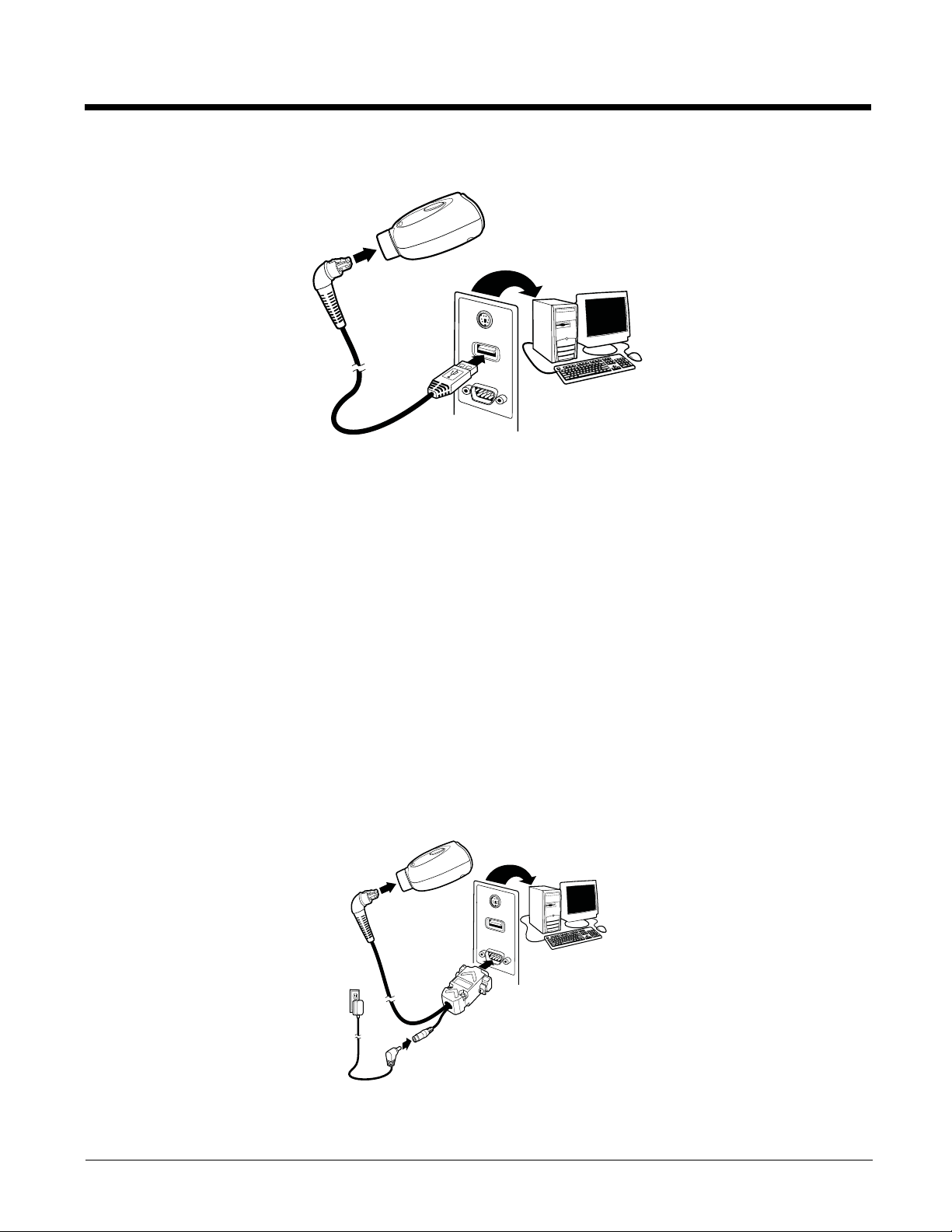
Connecting the Document Reader with TTL-232 Serial Port
Note: See "Document Reader Models" on page 1-1 to determine which interfaces apply to your
document reader.
1. Turn off power to the terminal/computer.
2. Connect the appropriate interface cable to the document reader.
Note: For the document reader to work properly, you must have the correct cable for your type of
terminal/computer.
3. Plug the serial connector into the serial port on your computer. Tighten the two screws to secure the
connector to the port.
1 - 2
Page 11
4. Plug the power supply into the cable.
IBM SurePos
(USB Hand Held Document
Reader) Interface
IBM SurePos
(USB Tabletop Document
Reader) Interface
5. Once the document reader has been fully connected, power up the computer.
6. Program the document reader for a TTL-232 Serial Port interface using the Plug and Play barcode
on page 1-5.
Supported Terminals
Terminal Terminal ID
TTL-232 000
USB COM Port Emulation 130 (default)
USB PC Keyboard 124
USB Mac Keyboard 125
USB POS 131
Programming the Interface - Plug and Play
Plug and Play barcodes provide instant document reader set up for commonly used interfaces.
USB Connection
IBM SurePos
Scan one of the following “Plug and Play” codes to program the document reader for IBM SurePos (USB
Hand Held document reader) or IBM SurePos (USB Tabletop document reader).
Note: After scanning one of these codes, you must power cycle the cash register.
Each barcode above also programs the following suffixes for each symbology:
Symbology Suffix
EAN-8 0C
EAN-13 16
UPC-A 0D
UPC-E 0A
Code 39 00 0A 0B
Interleaved 2 of 5 00 0D 0B
Code 128 00 18 0B
1 - 3
Page 12

USB PC or Macintosh® Keyboard
USB Keyboard (PC)
USB Keyboard (Mac)
USB Japanese Keyboard (PC)
USB HID Barcode Reader
USB COM Port Emulation
On
* Off
Scan one of the following codes to program the document reader for USB PC Keyboard or USB Macintosh Keyboard. Scanning these codes adds a CR and selects the terminal ID (USB PC Keyboard - 124,
USB Macintosh Keyboard - 125).
USB HID
Scan the following code to program the document reader for USB HID barcode readers. Scanning this
code changes the terminal ID to 131.
USB COM Port Emulation
Scan the following code to program the document reader to emulate a regular TTL-232-based COM
port. If you are using a Microsoft® Windows® PC, you will need to download a driver from the Honeywell website (www.honeywell.com/aidc). The driver will use the next available COM port number.
Apple® Macintosh computers recognize the document reader as a USB CDC class device and automatically use a class driver. Scanning the code below changes the terminal ID to 130.
Note: No extra configuration (e.g., baud rate) is necessary.
CTS/RTS Emulation
1 - 4
Page 13

ACK/NAK Mode
On
* Off
TTL-232 Interface
4800dr s/n
engine s/n
TTL-232 Serial Port Connection
All communication parameters between the document reader and terminal must match for correct data
transfer through the serial port using RS-232 protocol. Scanning the RS-232 interface barcode programs the document reader for an RS-232 interface at 115,200 baud, parity–none, 8 data bits, 1 stop bit,
and adds a suffix of a CR LF.
Aligning the Document Reader Tray
Proper cable placement is important for accurate alignment of the device. Place the cable in the wire
channel if the imager will remain in the base most of the time. If you plan to frequently lift out the imager
to scan items, then set the cable in the location where it will rest while the imager is in the stand.
Note: The 4800dr will not capture any images until it has been properly aligned using the following
procedure.
1. Loosen the screw in the base tray with a coin.
2. Place the alignment page on the tray. Align the upper left corner of the alignment page to the upper
left corner of the tray.
3. Make sure the serial number on the alignment page (the top number) matches the serial number on
your document reader.
4. Press the button on the imager to display the illuminated aimer crosshairs. You will hear a single
beep that indicates you are using the correct page.
(If you hear 3 beeps and the aimer turns off, then you have the wrong alignment page for your
document reader.)
5. Move the tray until the illuminated aimer crosshairs line up with the printed crosshairs on the
alignment page. (Be sure to wait until the crosshairs go off before removing power or attempting to
capture an image.)
6. Remove the alignment page and tighten the screw. Save the alignment page in the event that the
tray needs to be realigned in the future.
Note: If you need to print a new copy of the alignment page, make sure to print the page in landscape
mode.
1 - 5
Page 14
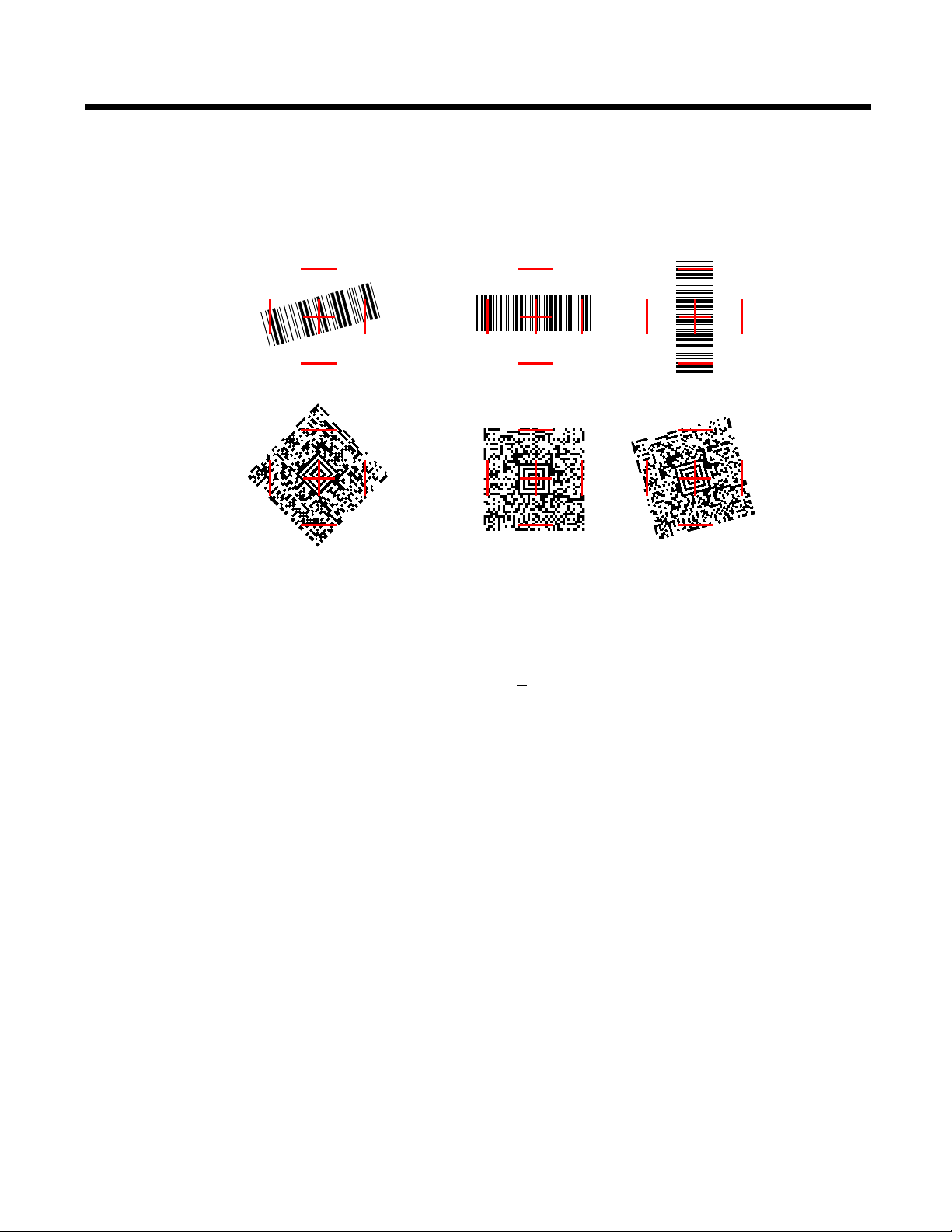
Reading Techniques
Linear barcodes:
2D Matrix symbols:
The document reader has a view finder that projects a bright aimer that corresponds to the document
reader’s horizontal field of view. The barcode should be centered under the aiming crosshairs, but can
be positioned in any direction for a good read.
The aimer is smaller when the barcode is closer to the document reader and larger when it is farther
away. Symbologies with smaller bars or elements (mil size) should be read closer to the unit. Symbologies with larger bars or elements (mil size) should be read farther from the unit. To read single or multiple symbols (on a page or on an object), hold the barcode at an appropriate distance from the document
reader, press the trigger, and center the aimer on the symbol. If the code being scanned is highly reflective (e.g., laminated), it may be necessary to tilt the code +
5° to prevent unwanted reflection.
Using the Imager Out of the Stand
If you remove the imager from the stand to read barcodes, you should hold it closer to the barcode. The
optimum read range is 6 to 7 inches (15.24 to 17.78cm). Since this is primarily a document imager and
works like a camera, you must hold the imager steady when scanning barcodes out of the stand.
1 - 6
Page 15
2
* United States
Brazil
Czech Republic
Denmark
Finland (Sweden)
France
Germany/Austria
Greece
Hungary
Belgium
Canada (French)
Israel (Hebrew)
Italy
Latin America
Norway
Netherlands (Dutch)
Terminal Interfaces
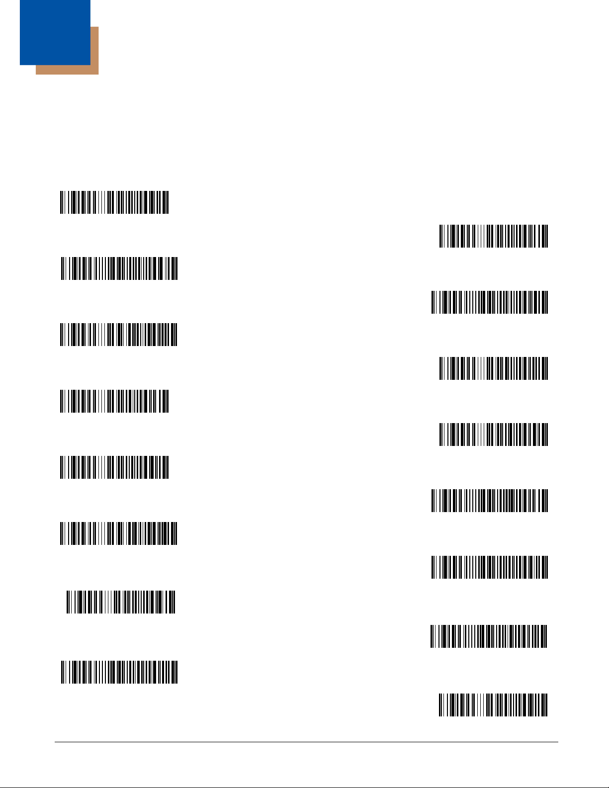
Keyboard Country
Scan the appropriate country code below to program the keyboard for your country. As a general rule,
the following characters are supported, but need special care for countries other than the United States:
@ | $ # { } [ ] = / ‘ \ < > ~
2 - 1
Page 16
Keyboard Country (continued)
Poland
Portugal
Romania
Russia
SCS
Slovakia
Spain
Sweden
Switzerland (German)
Turkey F
Turkey Q
U.K.
Program Keyboard Country
Please refer to the Honeywell website (www.honeywell.com/aidc) for complete keyboard country support
information and applicable interfaces. If you need to program a keyboard for a country other than one
listed above, scan the Program Keyboard Country barcode below, then scan the numeric barcode(s)
for the appropriate country from the inside back cover, then the Save barcode.
Keyboard Style
This programs keyboard styles, such as Caps Lock and Shift Lock.
Default = Regular.
2 - 2
Page 17

Regular is used when you normally have the Caps Lock key off.
* Regular
Caps Lock
Shift Lock
Automatic Caps Lock
Autocaps via NumLock
Emulate External Keyboard
Caps Lock
Shift Lock
Automatic Caps Lock
is used when you normally have the Caps Lock key on.
is used when you normally have the Shift Lock key on (not common to U.S. keyboards).
is used if you change the Caps Lock key on and off. The software tracks and
reflects if you have Caps Lock on or off (AT and PS/2 only). This selection can only be used with systems
that have an LED which notes the Caps Lock status.
Autocaps via NumLock
barcode should be scanned in countries (e.g., Germany, France) where the
Caps Lock key cannot be used to toggle Caps Lock. The NumLock option works similarly to the regular
Auotcaps, but uses the NumLock key to retrieve the current state of the Caps Lock.
Emulate External Keyboard
should be scanned if you do not have an external keyboard (IBM AT or
equivalent).
Note: After scanning the Emulate External Keyboard barcode, you must power cycle your computer.
Keyboard Modifiers
This modifies special keyboard features, such as CTRL+ ASCII codes and Turbo Mode.
2 - 3
Page 18
Control + ASCII Mode On: The document reader sends key combinations for ASCII control characters
Control + ASCII Mode On
* Control + ASCII Mode Off
Numeric Keypad Mode On
* Numeric Keypad Mode Off
300
2400
600
1200
4800
38400
9600
19200
* 115,200
57,600
for values 00-1F. Refer to Keyboard Function Relationships, page 8-1 for CTRL+ ASCII Values.
Default
= Off.
Numeric Keypad Mode: Sends numeric characters as if entered from a numeric keypad.
Default = Off.
TTL-232 Baud Rate
Baud Rate sends the data from the document reader to the terminal at the specified rate. The host terminal must be set for the same baud rate as the document reader.
Default = 115,200.
2 - 4
Page 19

RS-232 Word Length: Data Bits, Stop Bits, and Parity
* 8 Data, 1 Stop, Parity None
8 Data, 1 Stop, Parity Even
8 Data, 1 Stop, Parity Odd
TTL-232 Receiver Time-Out
Data Bits sets the word length at 8 bits of data per character.
Stop Bits sets the stop bits at 1.
Default = 1.
Parity provides a means of checking character bit patterns for validity.
Default = 8.
Default = None.
TTL-232 Receiver Time-Out
The unit stays awake to receive data until the TTL-232 Receiver Time-Out expires. A manual or serial
trigger resets the time-out. When a TTL-232 receiver is sleeping, a character may be sent to wake up
the receiver and reset the time-out. A transaction on the CTS line will also wake up the receiver. The
receiver takes 300 milliseconds to completely come up. Change the TTL-232 receiver time-out by scanning the barcode below, then scanning digits from the inside back cover of this manual, then scanning
Save. The range is 0 to 300 seconds.
Default = 0 seconds (no time-out - always on).
RS-232 Handshaking
TTL-232 Handshaking allows control of data transmission from the Document Reader using software
commands from the host device. When this feature is turned Off, no data flow control is used. When
Data Flow Control is turned On, the host device suspends transmission by sending the XOFF character
2 - 5
Page 20
(DC3, hex 13) to the Document Reader. To resume transmission, the host sends the XON character
RTS/CTS On
* XON/OFF Off
* RTS/CTS Off
XON/XOFF On
ACK/NAK On
* ACK/NAK Off
(DC1, hex 11). Data transmission continues where it left off when XOFF was sent.
XON/XOFF and ACK/NAK Off
.
Default = RTS/CTS,
2 - 6
Page 21
3
* On
Off
High
*Medium
Off
Low
Low (1600 Hz)
* Medium (3250 Hz)
High (4200 Hz)
Output
Good Read Indicators
Beeper – Good Read
The beeper may be programmed On or Off in response to a good read. Turning this option off, only
turns off the beeper response to a good read indication. All error and menu beeps are still audible.
Default = On.
Beeper Volume – Good Read
The beeper volume codes modify the volume of the beep the document reader emits on a good read.
Default = Medium.
Beeper Pitch – Good Read
The beeper pitch codes modify the pitch (frequency) of the beep the document reader emits on a good
read.
Default = Medium.
3 - 1
Page 22

Beeper Duration – Good Read
* Normal Beep
Short Beep
* On
Off
* LED Indicator Off
LED Indicator On
Number of Pulses
The beeper duration codes modify the length of the beep the document reader emits on a good read.
Default = Normal.
LED – Good Read
The LED indicator can be programmed On or Off in response to a good read.
Default = On.
LED – Indicator State
The LED indicator can be programmed to have an idle state of either Off or On, with a good read blink in
the opposite state. When programmed to LED Indicator Off, the LED indicator is Off in its idle state. It
blinks On for a good read, then returns to its idle Off state. When programmed to LED Indicator On, the
LED indicator is On in its idle state. It blinks Off for a good read, then returns to its idle On state. (LED
Indicator On can also be used as a power on indicator.)
Default = LED Indicator Off.
Number of Beeps – Good Read
The number of beeps of a good read can be programmed from 1 - 9. The same number of beeps will be
applied to the beeper and LED in response to a good read. For example, if you program this option to
have five beeps, there will be five beeps and five LED flashes in response to a good read. The beeps
and LED flashes are in sync with one another. To change the number of beeps, scan the barcode below
and then scan a digit (1-9) barcode and the Save barcode on the Programming Chart inside the back
cover of this manual.
3 - 2
Default = One.
Page 23

Good Read Delay
* No Delay
Short Delay (500 ms)
Medium Delay (1,000 ms)
Long Delay (1,500 ms)
User-Specified Good Read Delay
* Manual/Serial Trigger
This sets the minimum amount of time before the document reader can read another barcode.
Default =
No Delay.
User-Specified Good Read Delay
If you want to set your own length for the good read delay, scan the barcode below, then set the delay
(from 0-30,000 milliseconds) by scanning digits from the inside back cover, then scanning Save.
Trigger Modes
Manual/Serial Trigger
You can activate the document reader either by pressing the trigger, or using a serial trigger command
(see Trigger Commands on page 10-3). When in manual trigger mode, the document reader scans until
a barcode is read, or until the trigger is released.
When in serial mode, the document reader scans until a barcode has been read or until the deactivate
command is sent. In serial mode, the document reader can also be set to turn itself off after a specified
time has elapsed (see Read Time-Out, which follows).
Read Time-Out
Use this selection to set a time-out (in milliseconds) of the document reader’s trigger when using serial
commands to trigger the document reader, or if the document reader is in manual trigger mode. Once
the document reader has timed out, you can activate the document reader either by pressing the trigger
3 - 3
Page 24

or using a serial trigger command. After scanning the Read Time-Out barcode, set the time-out dura-
Read Time-Out
Scan Stand Mode
Scan Stand Symbol
Presentation Mode
tion (from 0-300,000 milliseconds) by scanning digits from the inside back cover, then scanning Save.
Default = 30,000.
Scan Stand Mode
When a unit is in Scan Stand mode, it remains idle as long as it sees the Scan Stand symbol. (See Scan
Stand Symbol on page 3-4.) When a different code is presented, the document reader is triggered to
read the new code.
Note: The document reader automatically adjusts the illumination LEDs to the lowest light level possible
to maintain a good lock on the Scan Stand symbol. When a symbol is presented, the document
reader’s light levels adjust to the saved setting (see LED Power Level on page 3-6). This mode
requires at least 50 lux of ambient light to operate correctly.
Scan Stand Symbol
When a unit is in Scan Stand mode, the LEDs shine at the Scan Stand Symbol on the base of the stand
which tells it to remain idle.
LEDs on at the configured power level (Default High) and attempts to find and decode barcodes in its
field of view.
When the Scan Stand symbol is covered, the document reader turns the
Presentation Mode
This programs the document reader to work in Presentation mode. The LEDs are either off or at the lowest power for ambient conditions until a barcode is presented to the document reader. Then the LEDs
turn on automatically to read the code. Presentation Mode uses ambient light to detect the barcodes. If
the light level in the room is not high enough, Presentation Mode may not work properly.
3 - 4
Page 25

Presentation Sensitivity
Sensitivity
Hands Free Time-Out
Short (500 ms)
* Medium (750 ms)
Long (1000 ms)
Extra Long (2000 ms)
Presentation Sensitivity is a numeric range that increases or decreases the document reader's reaction
time to barcode presentation. To set the sensitivity, scan the Sensitivity barcode, then scan the degree
of sensitivity (from 0-20) from the inside back cover, and Save. 0 is the most sensitive setting, and 20 is
the least sensitive.
Default = 1.
Hands Free Time-Out
The Scan Stand, and Presentation, and Streaming Presentation Modes are referred to as “hands free”
modes. If the document reader’s trigger is pulled when using a hands free mode, the document reader
changes to manual trigger mode. You can set the time the document reader should remain in manual
trigger mode by setting the Hands Free Time-Out. Once the time-out value is reached, (if there have
been no further trigger pulls) the document reader reverts to the original hands free mode.
Scan the Hands Free Time-Out
from the inside back cover, and Save.
barcode, then scan the time-out duration (from 0-300,000 milliseconds)
Default = 5,000 ms.
Reread Delay
This sets the time period before the document reader can read the
ting a reread delay protects against accidental rereads of the same barcode. Longer delays are effective
in minimizing accidental rereads. Use shorter delays in applications where repetitive barcode scanning
is required.
Default = Medium.
Reread Delay only works when in Presentation Mode or Hands Free Time-Out (page 3-5).
same
barcode a second time. Set-
3 - 5
Page 26

User-Specified Reread Delay
User-Specified Reread Delay
Off
Low (50%)
* High (100%)
Imager Time-Out
If you want to set your own length for the reread delay, scan the barcode below, then set the delay (from
0-30,000 milliseconds) by scanning digits from the inside back cover, then scanning Save.
LED Power Level
This selection allows you to adjust LED and aimer brightness. Off is used when no illumination is
needed. Low is used if low illumination is sufficient. High (the default) is the brightest setting.
If you have an aimer delay programmed (see Aimer Delay on page 3-7), the aimer will be at 100% power
during the delay, regardless of the LED Power Level.
Note: If you scan the Off barcode, both the aimer and illumination lights turn off, making it impossible
to scan barcodes in low light. To turn the LED Power Level back on, move to a brightly lit area
and scan either the Low or the High barcode below.
Default = High.
Imager Time-Out
Imager Time-Out powers down the document reader after the unit has been idle for the specified time.
To prevent the document reader from powering down, set this time-out to 0. Scan the barcode below,
then set the time-out by scanning digits (from 0 - 999,999 ms) from the inside back cover, then scanning
Save.
3 - 6
Default = 60,000 ms.
Page 27

Aimer Delay
400 milliseconds
* Off
(no delay)
200 milliseconds
Delay Duration
Off
* Interlaced
The aimer delay allows a delay time for the operator to aim the document reader before the picture is
taken. Use these codes to set the time between when the trigger is pulled and when the picture is taken.
During the delay time, the aiming light will appear, but the LEDs won’t turn on until the delay time is over.
Default = Off.
User-Specified Aimer Delay
If you want to set your own length for the duration of the delay, scan the barcode below, then set the timeout by scanning digits (0 - 4,000 ms) from the Programming Chart inside the back cover of this manual,
then scan Save.
Aimer Mode
This feature allows you to turn the aimer on and off. When the Interlaced barcode is scanned, the aimer
is interlaced with the illumination LEDs
. Default = Interlaced.
Centering
Use Centering to narrow the document reader’s field of view to make sure the document reader reads
only those barcodes intended by the user. For instance, if multiple codes are placed closely together,
centering will insure that only the desired codes are read. (Centering can be used in conjunction with
Aimer Delay, page 3-7, for the most error-free operation in applications where multiple codes are spaced
closely together. Using the Aimer Delay and Centering features, the document reader can emulate the
operation of older systems, such as linear laser barcode readers.)
3 - 7
Page 28
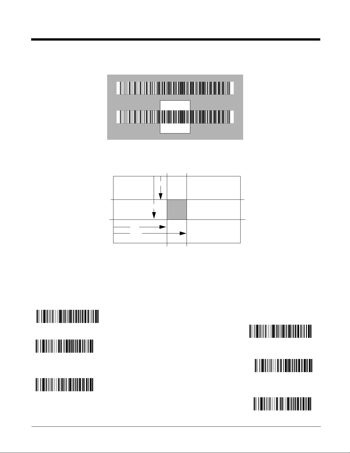
In the example below, the gray area is the full document reader field of view and the white area is the
Barcode 1
Barcode 2
0
100%
100%
Default
Center
40% 60%
40%
60%
Lef
Righ
Bottom
Top
Left of Centering Window
Top of Centering Window
Right of Centering Window
Bottom of Centering Window
* Centering Off
Centering On
centering window. Barcode 1 will not be read, while Barcode 2 will be.
The default centering window is a 128x96 pixel area in the center of the document reader’s field of view.
The following diagram illustrates the default top, bottom, left, and right pixel positions, measured from the
top and the left side of the document reader’s field of view, which is 640 by 480 pixels.
If a barcode is not within the predefined window, it will not be decoded or output by the document reader.
If centering is turned on by scanning Centering On, the document reader only reads codes that intersect the centering window you specify using the Top, Bottom, Left, or Right barcodes.
Scan Centering On, then scan one of the following barcodes to change the top, bottom, left, or right of
the centering window. Then scan the percent you want to shift the centering window using digits on the
inside back cover of this manual. Scan Save.
tom and Right.
3 - 8
Default Centering = 40% for Top and Left, 60% for Bot-
Page 29
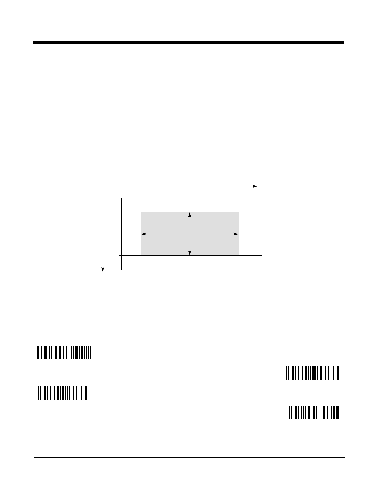
Decode Window
0
100%
100%
50%
50%
0
X
Y
16% 84%
20%
80%
68% X
60% Y
Default Decode Window Diagram:
Decode Window On
Decode Window Off
(Full FOV)
Decode Window X
Decode Window Y
This feature defines an area or window within which a barcode must be placed in order to be decoded.
Although the aimer brackets are displayed over a wide area, you can define a smaller window for decoding barcodes. This will improve decode time. Note that the barcode can only be decoded if it is entirely
within the defined window.
Setting a decode window does not change where the illuminated aimer brackets appear, so the user may
think the decode area is larger than it is. A user should center the barcode under the illuminated crosshairs to insure a proper read.
The decode window is based on the percentage of the field of view. The 4800dr defaults to
and
dow On, Decode Window X at 68%,
Decode Window Y at 60%
(this emulates the decode area of
Decode Win-
our other imaging products).
If you want the decode window to use the full field of view, scan the Decode Window Off (Full FOV) bar-
code. (Note that this slows decode time.)
To set a decode window, scan the Decode Window On barcode. Next set the percentage of the field of
view for the window by scanning the Decode Window X barcode and scanning up to 3 digits from the
inside back cover this manual to set the percentage of the field of view for the X setting. Scan the
Decode Window Y barcode and scan the digits for the percentage of the field of view for the Y setting.
Scan Save.
3 - 9
Page 30

Decode Search Mode
Full Omnidirectional
Quick Omnidirectional
Advanced Linear Decoding
There are three selectable decode (scanning) modes:
Full Omnidirectional
searches to the image’s limits. This mode reads all symbologies (including OCR), in any orientation.
The Full Omnidirectional search is very thorough which may slow performance time.
- Searches for barcode features beginning at the center of an image, and
Note: This search mode is the default setting.
Quick Omnidirectional
an image. This mode quickly reads all symbologies in any orientation. The Quick Omnidirectional mode
may miss some off-center symbols, as well as larger Data Matrix and QR Code symbols.
Advanced Linear Decoding
This mode is
Decoding cannot read 2D, OCR, or Postal symbols.
not
omnidirectional, but does quickly read linear and stacked barcodes. Advanced Linear
- This is an abbreviated search for barcode features around the center region of
- Performs quick horizontal linear scans in a center band of the image.
Preferred Symbology
Note: This selection does not apply to OCR.
The document reader can be programmed to specify one symbology as a higher priority over other symbologies in situations where both barcode symbologies appear on the same label, but the lower priority
symbology cannot be disabled.
For example, you may be using the document reader in a retail setting to read UPC symbols, but have
occasional need to read a code on a drivers license. Since some licenses have a Code 39 symbol as
well as the PDF417 symbol, you can use Preferred Symbology to specify that the PDF417 symbol be
read instead of the Code 39.
Preferred Symbology classifies each symbology as high priority, low priority, or as an unspecified
type. When a low priority symbology is presented, the document reader ignores it for a set period of
time (see Preferred Symbology Time-out on page 3-11) while it searches for the high priority symbology.
If a high priority symbology is located during this period, then that data is read immediately.
If the time-out period expires before a high priority symbology is read, the document reader will read any
barcode in its view (low priority or unspecified). If there is no barcode in the document reader’s view
after the time-out period expires, then no data is reported.
Note: A low priority symbol must be centered on the aiming pattern to be read.
3 - 10
Page 31

Scan a barcode below to enable or disable Preferred Symbology.
* Preferred Symbology Off
Preferred Symbology On
High Priority Symbology
Low Priority Symbology
Preferred Symbology Time-out
Preferred Symbology Default
High Priority Symbology
To specify the high priority symbology, scan the High Priority Symbology barcode below. On the
Symbology Chart on page A-1, find the symbology you want to set as high priority. Locate the Hex value
for that symbology and scan the 2 digit hex value from the Programming Chart (inside back cover). Scan
Save to save your selection.
Default = None
Low Priority Symbology
To specify the low priority symbology, scan the Low Priority Symbology barcode below. On the
Symbology Chart on page A-1, find the symbology you want to set as low priority. Locate the Hex value
for that symbology and scan the 2 digit hex value from the Programming Chart (inside back cover).
If you want to set additional low priority symbologies, scan FF, then scan the 2 digit hex value from the
Programming Chart for the next symbology. You can program up to 5 low priority symbologies. Scan
Save to save your selection.
Default = None
Preferred Symbology Time-out
Once you have enabled Preferred Symbology and entered the high and low priority symbologies, you
must set the time-out period. This is the period of time the document reader will search for a high priority
barcode after a low priority barcode has been encountered. Scan the barcode below, then set the delay
(from 100-3,000 milliseconds) by scanning digits from the inside back cover, then scanning Save.
Default = 500 ms.
Preferred Symbology Default
Scan the barcode below to set all Preferred Symbology entries to their default values.
3 - 11
Page 32

Output Sequence Overview
Require Output Sequence
When turned off, the barcode data will be output to the host as the Document Reader decodes it. When
turned on, all output data must conform to an edited sequence or the document reader will not transmit
the output data to the host device.
Note:This selection is unavailable when Multiple Symbols (page 3-14) is enabled.
Output Sequence Editor
This programming selection allows you to program the document reader to output data (when scanning
more than one symbol) in whatever order your application requires, regardless of the order in which the
barcodes are scanned. Reading the Default Sequence symbol programs the document reader to the
Universal values, shown below. These are the defaults. Be certain you want to delete or clear all formats before you read the Default Sequence symbol.
Note:To make Output Sequence Editor selections, you’ll need to know the code I.D., code length, and
character match(es) your application requires. Use the Alphanumeric symbols (inside back cover)
to read these options.
You must hold the trigger while reading each barcode in the sequence.
To Add an Output Sequence
1. Scan the Enter Sequence symbol (see Require Output Sequence, page 3-14).
2. Code I.D.
On the Symbology Chart on page A-1, find the symbology to which you want to apply the output
sequence format. Locate the Hex value for that symbology and scan the 2 digit hex value from the
Programming Chart (inside back cover).
3. Length
Specify what length (up to 9999 characters) of data output will be acceptable for this symbology.
Scan the four digit data length from the Programming Chart. (Note: 50 characters is entered as
0050. 9999 is a universal number, indicating all lengths.) When calculating the length, you must
count any programmed prefixes, suffixes, or formatted characters as part of the length (unless using
9999).
4. Character Match Sequences
On the ASCII Conversion Chart (Code Page 1252), page A-3, find the Hex value that represents the
character(s) you want to match. Use the Programming Chart to read the alphanumeric combination
that represents the ASCII characters. (99 is the Universal number, indicating all characters.)
5. End Output Sequence Editor
Scan F F to enter an Output Sequence for an additional symbology, or Save
Other Programming Selections
Discard
This exits without saving any Output Sequence changes.
to save your entries.
3 - 12
Page 33

Output Sequence Examples
A - Code 39
B - Code 128
C - Code 93
In this example, you are scanning Code 93, Code 128, and Code 39 barcodes, but you want the document reader to output Code 39 1st, Code 128 2nd, and Code 93 3rd, as shown below.
Note:Code 93 must be enabled to use this example.
You would set up the sequence editor with the following command line:
SEQBLK62999941FF6A999942FF69999943FF
The breakdown of the command line is shown below:
SEQBLK sequence editor start command
62 code identifier for Code 39
9999 code length that must match for Code 39, 9999 = all lengths
41 start character match for Code 39, 41h = “A”
FF termination string for first code
6A code identifier for Code 128
9999 code length that must match for Code 128, 9999 = all lengths
42 start character match for Code 128, 42h = “B”
FF termination string for second code
69 code identifier for Code 93
9999 code length that must match for Code 93, 9999 = all lengths
43 start character match for Code 93, 43h = “C”
FF termination string for third code
To program the previous example using specific lengths, you would have to count any programmed prefixes, suffixes, or formatted characters as part of the length. If you use the example on page 3-13, but
assume a <CR> suffix and specific code lengths, you would use the following command line:
SEQBLK62001241FF6A001342FF69001243FF
The breakdown of the command line is shown below:
SEQBLK sequence editor start command
62 code identifier for Code 39
0012 A - Code 39 sample length (11) plus CR suffix (1) = 12
41 start character match for Code 39, 41h = “A”
FF termination string for first code
6A code identifier for Code 128
0013 B - Code 128 sample length (12) plus CR suffix (1) = 13
42 start character match for Code 128, 42h = “B”
FF termination string for second code
69 code identifier for Code 93
0012 C - Code 93 sample length (11) plus CR suffix (1) = 12
3 - 13
Page 34

43 start character match for Code 93, 43h = “C”
Enter Sequence
Default Sequence
Required
On/Not Required
*Off
On
* Off
FF termination string for third code
Output Sequence Editor
Require Output Sequence
When an output sequence is Required, all output data must conform to an edited sequence or the document reader will not transmit the output data to the host device. When it’s On/Not Required, the document reader will attempt to get the output data to conform to an edited sequence, but if it cannot, the
document reader transmits all output data to the host device as is.
When the output sequence is Off, the barcode data is output to the host as the document reader
decodes it.
Note: This selection is unavailable when the Multiple Symbols Selection is turned on.
Default = Off.
Multiple Symbols
When this programming selection is turned On, it allows you to read multiple symbols with a single pull
of the Document Reader’s trigger. If you press and hold the trigger, aiming the Document Reader at a
series of symbols, it reads unique symbols once, beeping (if turned on) for each read. The document
reader attempts to find and decode new symbols as long as the trigger is pulled. When this programming selection is turned Off, the Document Reader will only read the symbol closest to the aiming beam.
Default = Off.
3 - 14
Page 35

No Read
On
* Off
Set Print Weight
* Default
On
* Off
With No Read turned On, the Document Reader notifies you if a code cannot be read. The document
reader outputs an “NR” appears when a code cannot be read. If No Read is turned Off, the “NR” will not
appear.
If you want a different notation than “NR,” for example, “Error,” or “Bad Code,” you can edit the output
message using the Data Formatter (page 5-4). The hex code for the No Read symbol is 9C.
Default = Off.
Print Weight
Print Weight is used to adjust the way the document reader reads Matrix symbols. If a document reader
will be seeing consistently heavily printed matrix symbols, then a print weight of 6 may improve the reading performance. For consistently light printing, a print weight of 2 may help. After scanning the Set
Print Weight
scanning Save.
barcode, set the print weight (from 1-7) by scanning digits from the inside back cover, then
Default = 4
.
Video Reverse
Video Reverse is used to allow the document reader to read barcodes that are inverted. The Off barcode below is an example of this type of barcode. If additional menuing is required, Video Reverse must
be disabled to read the menu barcodes and then re-enabled after menuing is completed.
Default = Off.
Note: Images downloaded from the unit will not be reversed. This is a setting for decoding only.
Mandatory Alignment Flag
The 4800dr can be set to require that the reader tray be aligned properly before an image can be
snapped and shipped. This prevents users from capturing images on an unaligned 4800dr, which can
result in poor quality images. If the Mandatory Alignment Flag is On, no images will be captured until the
3 - 15
Page 36

alignment has been performed using an alignment page. If the mandatory alignment flag is Off, images
* Mandatory Alignment Flag On
Mandatory Alignment Flag Off
Upright:
Rotate Code Clockwise 90°:
Upside Down:
Rotate Code
Counterclockwise 90°:
* Upright
Rotate Code Clockwise 90°
Upside Down
Rotate Code
Counterclockwise 90°
can be captured whether or not the device has been aligned properly.
Default = Mandatory Alignment
Flag On.
Working Orientation
Some barcodes are direction-sensitive. For example, KIX codes and OCR can misread when scanned
sideways or upside down. Use the working orientation settings if your direction-sensitive codes will not
usually be presented upright to the document reader.
Default = Upright.
3 - 16
Page 37

4
Data Editing
Prefix/Suffix Overview
When a barcode is scanned, additional information is sent to the host computer along with the barcode
data. This group of barcode data and additional, user-defined data is called a “message string.” The
selections in this section are used to build the user-defined data into the message string.
Prefix and Suffix characters are data characters that can be sent before and after scanned data. You
can specify if they should be sent with all symbologies, or only with specific symbologies. The following
illustration shows the breakdown of a message string:
Prefix
alpha numeric
characters
Scanned Data
variable length1-11
Suffix
1-11
alpha numeric
characters
Points to Keep In Mind
• It is not necessary to build a message string. The selections in this chapter are only used if you wish
to alter the default settings.
• A prefix or suffix may be added or cleared from one symbology or all symbologies.
• You can add any prefix or suffix from the ASCII Conversion Chart (Code Page 1252), page A-3, plus
Code I.D. and AIM I.D.
• You can string together several entries for several symbologies at one time.
• Enter prefixes and suffixes in the order in which you want them to appear on the output.
• When setting up for specific symbologies, instead of All Symbologies, the symbology ID value counts
as an added prefix or suffix character.
Default prefix = None. Default suffix = None
.
4 - 1
Page 38

To Add a Prefix or Suffix:
Step 1. Scan the Add Prefix or Add Suffix symbol (page 4-3).
Step 2. Determine the 2 digit Hex value from the Symbology Chart (included in Appendix A) for the
symbology to which you want to apply the prefix or suffix. For example, for Code 128, Code ID
is “j” and Hex ID is “6A”.
Step 3. Scan the 2 hex digits from the Programming Chart inside the back cover of this manual or scan
9, 9 for all symbologies.
Step 4. Determine the hex value from the ASCII Conversion Chart (Code Page 1252), page A-3, for
the prefix or suffix you wish to enter.
Step 5. Scan the 2 digit hex value from the Programming Chart inside the back cover of this manual.
Step 6. Repeat Steps 4 and 5 for every prefix or suffix character.
Step 7. To add the Code I.D., scan 5, C, 8, 0.
To add AIM I.D., scan 5, C, 8, 1.
To add a backslash (\), scan 5, C, 5, C.
Note: To add a backslash (\) as in Step 7, you must scan 5C twice – once to create the leading
backslash and then to create the backslash itself.
Step 8. Scan Save to exit and save, or scan Discard to exit without saving.
Repeat Steps 1-6 to add a prefix or suffix for another symbology.
Example: Add a Suffix to a specific symbology
To send a CR (carriage return)Suffix for UPC only:
Step 1. Scan Add Suffix.
Step 2. Determine the 2 digit hex value from the Symbology Chart (included in Appendix A) for UPC.
Step 3. Scan 6, 3 from the Programming Chart inside the back cover of this manual.
Step 4. Determine the hex value from the ASCII Conversion Chart (Code Page 1252), page A-3, for
the CR (carriage return).
Step 5. Scan 0, D from the Programming Chart inside the back cover of this manual.
Step 6. Scan Save, or scan Discard to exit without saving.
To Clear One or All Prefixes or Suffixes:
You can clear a single prefix or suffix, or clear all prefixes/suffixes for a symbology. When you Clear One
Prefix (Suffix), the specific character you select is deleted from the symbology you want. When you Clear
All Prefixes (Suffixes), all the prefixes or suffixes for a symbology are deleted.
4 - 2
Page 39

Step 1. Scan the Clear One Prefix or Clear One Suffix symbol.
Add CR Suffix
All Symbologies
Add Prefix
Clear One Prefix
Clear All Prefixes
Add Suffix
Clear One Suffix
Clear All Suffixes
Step 2. Determine the 2 digit Hex value from the Symbology Chart (included in Appendix A) for the
symbology from which you want to clear the prefix or suffix.
Step 3. Scan the 2 digit hex value from the Programming Chart inside the back cover of this manual or
scan 9, 9 for all symbologies.
Your change is automatically saved.
To Add a Carriage Return Suffix to all Symbologies
Scan the following barcode if you wish to add a carriage return suffix to all symbologies at once. This
action first clears all current suffixes, then programs a carriage return suffix for all symbologies.
Prefix Selections
Suffix Selections
4 - 3
Page 40

Function Code Transmit
* Enable
Disable
1 2345
Intercharacter Delay
Prefix Scanned Data Suffix
Intercharacter Delay
When this selection is enabled and function codes are contained within the scanned data, the document
reader transmits the function code to the terminal. Charts of these function codes are provided in
Supported Interface Keys starting on page 8-2. When the document reader is in keyboard wedge mode,
the scan code is converted to a key code before it is transmitted.
Default = Enable.
Intercharacter, Interfunction, and Intermessage Delays
Some terminals drop information (characters) if data comes through too quickly. Intercharacter, interfunction, and intermessage delays slow the transmission of data, increasing data integrity.
Each delay is composed of a 5 millisecond step. You can program up to 99 steps (of 5 ms each) for a
range of 0-495 ms.
Intercharacter Delay
An intercharacter delay of up to 495 milliseconds (in 5 ms steps) may be placed between the transmission of each character of scanned data. Scan the
number of 5 millisecond steps (0-99), and the Save barcode using the Programming Chart inside the
back cover of this manual.
Intercharacter Delay barcode below, then scan the
To remove this delay, scan the Intercharacter Delay barcode, then set the number of steps to 0. Scan
the Save barcode using the Programming Chart inside the back cover of this manual.
Note: Intercharacter delays are not supported in USB serial emulation.
User Specified Intercharacter Delay
An intercharacter delay of up to 495 milliseconds (in 5 ms steps) may be placed after the transmission of
a particular character of scanned data. Scan the Delay Length barcode below, then scan the number of
5 millisecond steps (0-99), and the Save barcode using the Programming Chart inside the back cover of
this manual.
4 - 4
Page 41

Next, scan the Character to Trigger Delay barcode, then the 2-digit hex value for the ASCII character
Delay Length
Character to Trigger Delay
Interfunction Delays
Prefix Scanned Data Suffix
1 2345STX HT CR LF
Interfunction Delay
2nd Scan Transmission1st Scan Transmission
Intermessage Delay
Intermessage Delay
that will trigger the delay ASCII Conversion Chart (Code Page 1252), page A-3.
To remove this delay, scan the Delay Length barcode, and set the number of steps to 0. Scan the Save
barcode using the Programming Chart inside the back cover of this manual.
Interfunction Delay
An interfunction delay of up to 495 milliseconds (in 5 ms steps) may be placed between the transmission
of each segment of the message string. Scan the Interfunction Delay barcode below, then scan the
number of 5 millisecond steps (0-99), and the Save barcode using the Programming Chart inside the
back cover of this manual.
To remove this delay, scan the Interfunction Delay barcode, then set the number of steps to 0. Scan
the Save barcode using the Programming Chart inside the back cover of this manual.
Intermessage Delay
An intermessage delay of up to 495 milliseconds (in 5 ms steps) may be placed between each scan
transmission. Scan the
steps (0-99), and the Save barcode using the Programming Chart inside the back cover of this manual.
To remove this delay, scan the
the Save barcode using the Programming Chart inside the back cover of this manual.
Intermessage Delay barcode below, then scan the number of 5 millisecond
Intermessage Delay barcode, then set the number of steps to 0. Scan
4 - 5
Page 42

4 - 6
Page 43

5
Data Formatting
Data Format Editor Introduction
You may use the Data Format Editor to change the document reader’s output. For example, you can use
the Data Format Editor to insert characters at certain points in barcode data as it is scanned. The selections in the following pages are used only if you wish to alter the output.
None.
Normally, when you scan a barcode, it gets outputted automatically; however when you do a format, you
must use a “send” command (see Send Commands on page 5-2) within the format program to output
data.
Multiple formats may be programmed into the document reader. They are stacked in the order in which
they are entered. However, the following list presents the order in which formats are applied:
1. Specific Term ID, Actual Code ID, Actual Length
2. Specific Term ID, Actual Code ID, Universal Length
3. Specific Term ID, Universal Code ID, Actual Length
Default Data Format setting =
4. Specific Term ID, Universal Code ID, Universal Length
5. Universal Term ID, Actual Code ID, Actual Length
6. Universal Term ID, Actual Code ID, Universal Length
7. Universal Term ID, Universal Code ID, Actual Length
8. Universal Term ID, Universal Code ID, Universal Length
If you have changed data format settings, and wish to clear all formats and return to the factory defaults,
scan the Default Data Format code on page 5-4.
To Add a Data Format
Step 1. Scan the Enter Data Format symbol (page 5-4).
Step 2. Primary/Alternate Format
Determine if this will be your primary data format, or one of 3 alternate formats. (Alternate formats allow you “single shot” capability to scan one barcode using a different data format. After
the one barcode has been read, the document reader reverts to the primary data format. See
page 5-4.) If you are programming the primary format, scan 0 using the Programming Chart
inside the back cover of this manual. If you are programming an alternate format, scan 1, 2, or
3, depending on the alternate format you are programming.
Step 3. Terminal Type
Refer to Supported Terminals (page 1-3) and locate the Terminal ID number for your PC.
Scan three numeric barcodes on the inside back cover to program the document reader for
your terminal ID (you must enter 3 digits). For example, scan 0 0 3 for an AT wedge.
Note: The wildcard for all terminal types is 099.
Step 4. Code I.D.
In Appendix A, find the symbology to which you want to apply the data format. Locate the Hex
5 - 1
Page 44

value for that symbology and scan the 2 digit hex value from the Programming Chart inside the
back cover of this manual.
Step 5. Length
Specify what length (up to 9999 characters) of data will be acceptable for this symbology.
Scan the four digit data length from the Programming Chart inside the back cover of this manual. (Note: 50 characters is entered as 0050. 9999 is a universal number, indicating all
lengths.)
Step 6. Editor Commands
Refer to Data Format Editor Commands (page 5-2). Scan the symbols that represent the command you want to enter. 94 alphanumeric characters may be entered for each symbology
data format.
Step 7. Scan Save from the Programming Chart inside the back cover of this manual to save your
entries.
Other Programming Selections
• Clear One Data Format
This deletes one data format for one symbology. If you are clearing the primary format, scan 0 from
the Programming Chart inside the back cover of this manual. If you are clearing an alternate format,
scan 1, 2, or 3, depending on the alternate format you are clearing. Scan the Terminal Type and Code
I.D. (see Supported Terminals on page 1-3), and the barcode data length for the specific data format
that you want to delete. All other formats remain unaffected.
• Save from the Programming Chart inside the back cover of this manual
This exits, saving any Data Format changes.
• Discard from the Programming Chart inside the back cover of this manual
This exits without saving any Data Format changes.
Data Format Editor Commands
Send Commands
F1 Send all characters followed by “xx” key or function code, starting from current cursor position.
Syntax = F1xx
(Code Page 1252), page A-3.)
F2 Send “nn” characters followed by “xx” key or function code, starting from current cursor position.
Syntax = F2nnxx
stands for the hex value for an ASCII code. See ASCII Conversion Chart (Code Page
1252), page A-3.)
F3 Send up to but not including “ss” character (Search and Send) starting from current cursor posi-
tion, leaving cursor pointing to “ss” character followed by “xx” key or function code.
F3ssxx
(Code Page 1252), page A-3.)
F4 Send “xx” character “nn” times (Insert) leaving cursor in current cursor position.
F4xxnn
1252), page A-3, and nn is the numeric value (00-99) for the number of times it should be sent.)
E9 Send all but the last “nn” characters, starting from the current cursor position.
(nn is the numeric value (00-99) for the number of characters that will not be sent at the end of
the message.)
(ss and xx both stand for the hex values for ASCII codes, see ASCII Conversion Chart
(xx stands for the hex value for an ASCII code, see ASCII Conversion Chart (Code Page
(xx stands for the hex value for an ASCII code, see ASCII Conversion Chart
(nn stands for the numeric value (00-99) for the number of characters and xx
Syntax =
Syntax =
Syntax = E9nn
5 - 2
Page 45

Move Commands
F5 Move the cursor ahead “nn” characters from current cursor position.
Syntax = F5nn
(nn stands for the numeric value (00-99) for the number of characters the cursor
should be moved ahead.)
F6 Move the cursor back “nn” characters from current cursor position.
Syntax = F6nn
(nn stands for the numeric value (00-99) for the number of characters the cursor
should be moved back.)
F7 Move the cursor to the beginning of the data string.
EA Move the cursor to the end of the data string.
Syntax = F7.
Syntax = EA
Search Commands
F8 Search ahead for “xx” character from current cursor position, leaving cursor pointing to “xx” char-
acter.
Syntax = F8xx
(xx stands for the hex value for an ASCII code, see ASCII Conversion
Chart (Code Page 1252), page A-3.)
F9 Search back for “xx” character from current cursor position, leaving cursor pointing to “xx” char-
acter.
Syntax = F9xx
(xx stands for the hex value for an ASCII code, see ASCII Conversion
Chart (Code Page 1252), page A-3.)
E6 Search ahead for the first non “xx” character from the current cursor position, leaving cursor
pointing to non “xx” character.
Syntax = E6xx
(xx stands for the hex value for an ASCII code,
see ASCII Conversion Chart (Code Page 1252), page A-3.
E7 Search back for the first non “xx” character from the current cursor position, leaving cursor point-
ing to non “xx” character.
Syntax = E7xx
(xx stands for the hex value for an ASCII code, see
ASCII Conversion Chart (Code Page 1252), page A-3.)
Miscellaneous Commands
FB Suppress all occurrences of up to 15 different characters, starting at the current cursor position,
as the cursor is advanced by other commands. When the FC command is encountered, the sup-
press function is terminated. The cursor is not moved by the FB command. Syntax = FBnnxxyy
. .zz where nn is a count of the number of suppressed characters in the list and xxyy .. zz is the
list of characters to be suppressed. (xx stands for the hex value for an ASCII code, see ASCII
Conversion Chart (Code Page 1252), page A-3.)
FC Disables suppress filter and clear all suppressed characters.
Syntax = FC.
E4 Replaces up to 15 characters in the data string with user specified characters. Replacement
continues until the E5 command is encountered.
nn is the total count of both characters to be replaced plus replacement characters; xx
characters to be replaced and xx
.
zz
2
defines replacement characters, continuing through zz1 and
2
E5 Terminates character replacement.
Syntax = E5.
Syntax = E4nnxx1xx2yy1yy2...zz1zz
where
2
defines
1
FE Compare character in current cursor position to the character “xx.” If characters are equal, incre-
ment cursor. If characters are not equal, no format match.
Syntax = FExx
(xx stands for the
hex value for an ASCII code, see ASCII Conversion Chart (Code Page 1252), page A-3.)
EC Check to make sure there is an ASCII number at the current cursor position. If character is not
numeric, format is aborted.
Syntax = EC
.
ED Check to make sure there is a non-numeric ASCII character at the current cursor position. If
character is numeric, format is aborted.
Syntax = ED
.
5 - 3
Page 46

Data Format Editor
Enter Data Format
* Default Data Format
Clear One Data Format
Save
Discard
Clear All Data Formats
Data Formatter Off
* Data Formatter On,
but Not Required
Data Format On, Format Required
Data Formatter
When Data Formatter is turned off, the barcode data is output to the host as read (including prefixes and
suffixes). Choose one of the following options.
Default = Data Formatter On, but Not Required.
When Data Formatter is required, all input data must conform to an edited format or the document
reader does not transmit the input data to the host device.
Alternate Data Formats
Alternate formats allow you “single shot” capability to scan one barcode using a different data format
than your primary format. When data formats are programmed (see page 5-1), you must input whether
you are programming the primary format, or an alternate format numbered 1, 2, or 3.
5 - 4
Page 47

An alternate format is initiated by scanning one of the 3 alternate format barcodes below. The document
Alternate Data Format 1
Alternate Data Format 2
Alternate Data Format 3
reader will scan the next barcode, formatting the data with the selected alternate format, then revert
immediately to the primary format.
5 - 5
Page 48

5 - 6
Page 49

6
All Symbologies On
All Symbologies Off
Symbologies
This programming section contains the following menu selections. Refer to Chapter 10 for settings and
defaults.
• All Symbologies • Kix (Netherlands) Post
• Intelligent Mail Barcode • Korea Post
• Australian Post • Matrix 2 of 5
• Aztec Code • MaxiCode
• British Post • MicroPDF417
• Canadian Post • MSI
• China Post • PDF417
• Codabar • Planet Code
• Codablock F • Plessey Code
• Code 11 • PosiCode A and B
• Code 128 • Postnet
• Code 16K • QR Code
• Code 39 • GS1 DataBar Expanded
• Code 49 • GS1 DataBar Limited
• Code 93 • GS1 DataBar
• Data Matrix • Straight 2 of 5 IATA
• EAN/JAN-13 • Straight 2 of 5 Industrial
• EAN/JAN-8 • TCIF Linked Code 39 (TLC39)
• EAN•UCC Composite Codes • Telepen
• Interleaved 2 of 5 • Trioptic Code
• ID-tag (UPU 4-State) • UPC-A
• Japanese Post
• UPC-A/EAN-13 with Extended Coupon
Code
All Symbologies
If you want to decode all the symbologies allowable for your document reader, scan the All Symbologies On code. If on the other hand, you want to decode only a particular symbology, scan All Symbol-
ogies Off followed by the On symbol for that particular symbology.
6 - 1
Page 50

Message Length Description
* On
Off
Transmit
* Don’t Transmit
You are able to set the valid reading length of some of the barcode symbologies. If the data length of
the scanned barcode doesn’t match the valid reading length, the document reader will issue an error
beep. You may wish to set the same value for minimum and maximum length to force the document
reader to read fixed length barcode data. This helps reduce the chances of a misread.
EXAMPLE: Decode only those barcodes with a count of 9-20 characters.
Min. length = 09 Max. length = 20
EXAMPLE: Decode only those barcodes with a count of 15 characters.
Min. length = 15 Max. length = 15
For a value other than the minimum and maximum message length defaults, scan the barcodes included
in the explanation of the symbology, then scan the digit value of the message length and Save barcodes
on the Programming Chart inside the back cover of this manual. The minimum and maximum lengths
and the defaults are included with the respective symbologies.
Codabar
<Default All Codabar Settings>
Codabar
Codabar Start/ Stop Characters
Start/Stop characters identify the leading and trailing ends of the barcode. You may either transmit, or
not transmit Start/Stop characters.
Default = Don’t Transmit
.
Codabar Check Character
Codabar check characters are created using different “modulos.” You can program the document reader
to read only Codabar barcodes with Modulo 16 check characters.
No Check Character indicates that the document reader reads and transmits barcode data with or without a check character.
When Check Character is set to Validate and Transmit, the document reader will only read Codabar
barcodes printed with a check character, and will transmit this character at the end of the scanned data.
6 - 2
Default = No Check Character.
Page 51

When Check Character is set to Validate, but Don’t Transmit, the unit will only read Codabar barcodes
* No Check Character
Validate Modulo 16
and Transmit
Validate Modulo 16, but
Don’t Transmit
A12D D34A
Codabar
Character
Stop Start StopStart
On
* Off
Require
Minimum Message Length
Maximum Message Length
with
printed
a check character, but will not transmit the check character with the scanned data.
Codabar Concatenation
Codabar supports symbol concatenation. When you enable concatenation, the document reader looks
for a Codabar symbol having a “D” start character, adjacent to a symbol having a “D” stop character. In
this case the two messages are concatenated into one with the “D” characters omitted.
Default = On.
Select Require to prevent the document reader from decoding a single “D” Codabar symbol without its
companion. This selection has no effect on Codabar symbols without Stop/Start D characters.
Codabar Message Length
Scan the barcodes below to change the message length. Refer to Message Length Description (page 6-
2) for additional information. Minimum and Maximum lengths = 2-60. Minimum Default = 4, Maximum
Default = 60.
6 - 3
Page 52

Code 39
* On
Off
Transmit
* Don’t Transmit
Validate, but Don’t Transmit
* No Check Character
Validate and Transmit
< Default All Code 39 Settings >
Code 39
Code 39 Start/ Stop Characters
Start/Stop characters identify the leading and trailing ends of the barcode. You may either transmit, or
not transmit Start/Stop characters.
Default = Don’t Transmit.
Code 39 Check Character
No Check Character indicates that the document reader reads and transmits barcode data with or with-
out a check character.
When Check Character is set to Validate, but Don’t Transmit, the unit only reads Code 39 barcodes
printed with a check character, but will not transmit the check character with the scanned data.
When Check Character is set to Validate and Transmit, the document reader only reads Code 39 bar-
codes printed with a check character, and will transmit this character at the end of the scanned data.
Default = No Check Character.
6 - 4
Page 53

Code 39 Message Length
Minimum Message Length
Maximum Message Length
* Off
On
* Off
On
Scan the barcodes below to change the message length. Refer to Message Length Description (page 6-
2) for additional information. Minimum and Maximum lengths = 0-48. Minimum Default = 0, Maximum
Default = 48.
Code 39 Append
This function allows the document reader to append the data from several Code 39 barcodes together
before transmitting them to the host computer. When this function is enabled, the document reader
stores those Code 39 barcodes that start with a space (excluding the start and stop symbols), and does
not immediately transmit the data. The document reader stores the data in the order in which the barcodes are read, deleting the first space from each. The document reader transmits the appended data
when it reads a Code 39 barcode that starts with a character other than a space.
Default = Off.
Code 32 Pharmaceutical (PARAF)
Code 32 Pharmaceutical is a form of the Code 39 symbology used by Italian pharmacies. This symbology is also known as PARAF.
Note: Trioptic Code (page 6-25) must be turned off while scanning Code 32 Pharmaceutical codes.
6 - 5
Page 54

Full ASCII
* Full ASCII Off
Full ASCII On
Code 39 Code Page
If Full ASCII Code 39 decoding is enabled, certain character pairs within the barcode symbol will be
interpreted as a single character. For example: $V will be decoded as the ASCII character SYN, and /C
will be decoded as the ASCII character #.
NUL %U DLE $P SPSPACE 00@%V PP‘%W p+P
SOH $A
STX $B
ETX $C
EOT $D
ENQ $E
ACK $F
BEL $G
BS $H
HT $I
LF $J
VT $K
FF $L
CR $M
SO $N
SI $O
DC1 $Q !/A11AAQQa+A q+Q
DC2 $R “/B22BBRRb+B r+R
DC3 $S #/C33CCSSc+C s+S
DC4 $T $/D44DDTTd+D t+T
NAK $U %/E 55EEUUe+E u+U
SYN $V &/F66FFVVf+Fv+V
ETB $W ‘/G77GGWW g+G w+W
CAN $X (/H88HHXXh+H x+X
EM $Y )/I99IIYYi+Iy+Y
SUB $Z */J:/ZJJZZj+Jz+Z
ESC %A +/K;%FKK[%K k+K {%P
FS %B ,/L<%G LL\%Ll+L|%Q
GS %C --=%H MM]%M m+M }%R
RS %D ..>%I NN^%N n+N ~%S
US %E //O?%J OO_%O o+O DEL %T
Character pairs /M and /N decode as a minus sign and period respectively. Character pairs /P through /
Y decode as 0 through 9.
Default = Off
.
Code 39 Code Page
Code pages define the mapping of character codes to characters. If the data received does not display
with the proper characters, it may be because the barcode being scanned was created using a code
page that is different from the one the host program is expecting. If this is the case, scan the barcode
below, select the code page with which the barcodes were created (see Code Page Mapping of Printed
Barcodes on page A-4), and scan the value and the Save barcode from the Programming Chart on the
inside the back cover of this manual. The data characters should then appear properly.
6 - 6
Page 55

Interleaved 2 of 5
* On
Off
Validate, but Don’t Transmit
* No Check Digit
Validate and Transmit
Minimum Message Length
Maximum Message Length
< Default All Interleaved 2 of 5 Settings >
Interleaved 2 of 5
Check Digit
No Check Digit indicates that the document reader reads and transmits barcode data with or without a
check digit.
When Check Digit is set to Validate, but Don’t Transmit, the unit only reads Interleaved 2 of 5 barcodes
printed with a check digit, but will not transmit the check digit with the scanned data.
When Check Digit is set to Validate and Transmit, the document reader only reads Interleaved 2 of 5
barcodes printed with a check digit, and will transmit this digit at the end of the scanned data.
No Check Digit.
Default =
Interleaved 2 of 5 Message Length
Scan the barcodes below to change the message length. Refer to Message Length Description (page 6-
2) for additional information. Minimum and Maximum lengths = 2-80. Minimum Default = 4, Maximum
Default = 80.
6 - 7
Page 56

Code 93
* On
Off
Minimum Message Length
Maximum Message Length
Code 93 Code Page
< Default All Code 93 Settings >
Code 93
Code 93 Message Length
Scan the barcodes below to change the message length. Refer to Message Length Description (page 6-
2) for additional information. Minimum and Maximum lengths = 0-80. Minimum Default = 0, Maximum
Default = 80.
Code 93 Code Page
Code pages define the mapping of character codes to characters. If the data received does not display
with the proper characters, it may be because the barcode being scanned was created using a code
page that is different from the one the host program is expecting. If this is the case, scan the barcode
below, select the code page with which the barcodes were created (see Code Page Mapping of Printed
Barcodes on page A-4), and scan the value and the Save barcode from the Programming Chart on the
inside the back cover of this manual. The data characters should then appear properly.
6 - 8
Page 57

Straight 2 of 5 Industrial
On
* Off
Minimum Message Length
Maximum Message Length
<Default All Straight 2 of 5 Industrial Settings>
Straight 2 of 5 Industrial
Straight 2 of 5 Industrial Message Length
Scan the barcodes below to change the message length. Refer to Message Length Description (page 6-
2) for additional information. Minimum and Maximum lengths = 1-48. Minimum Default = 4, Maximum
Default = 48.
6 - 9
Page 58

Straight 2 of 5 IATA (Two-Bar Start/Stop)
On
* Off
Minimum Message Length
Maximum Message Length
<Default All Straight 2 of 5 IATA Settings>
Straight 2 of 5 IATA
Straight 2 of 5 IATA Message Length
Scan the barcodes below to change the message length. Refer to Message Length Description (page 6-
2) for additional information. Minimum and Maximum lengths = 1-48. Minimum Default = 4, Maximum
Default = 48.
6 - 10
Page 59

Matrix 2 of 5
On
* Off
Minimum Message Length
Maximum Message Length
On
* Off
<Default All Matrix 2 of 5 Settings>
Matrix 2 of 5
Matrix 2 of 5 Message Length
Scan the barcodes below to change the message length. Refer to Message Length Description (page 6-
2) for additional information. Minimum and Maximum lengths = 1-80. Minimum Default = 4, Maximum
Default = 80.
Code 11
Code 11
<Default All Code 11 Settings>
6 - 11
Page 60

Check Digits Required
One Check Digit
* Two Check Digits
Minimum Message Length
Maximum Message Length
* On
Off
This option sets whether 1 or 2 check digits are required with Code 11 barcodes.
Default = Two Check
Digits.
Code 11 Message Length
Scan the barcodes below to change the message length. Refer to Message Length Description (page 6-
2) for additional information. Minimum and Maximum lengths = 1-80. Minimum Default = 4, Maximum
Default = 80.
Code 128
<Default All Code 128 Settings>
Code 128
ISBT 128 Concatenation
In 1994 the International Society of Blood Transfusion (ISBT) ratified a standard for communicating critical blood information in a uniform manner. The use of ISBT formats requires a paid license. The ISBT
128 Application Specification describes 1) the critical data elements for labeling blood products, 2) the
current recommendation to use Code 128 due to its high degree of security and its space-efficient
6 - 12
Page 61

design, 3) a variation of Code 128 that supports concatenation of neighboring symbols, and 4) the stan-
* Off
On
Minimum Message Length
Maximum Message Length
Code 128 Code Page
dard layout for barcodes on a blood product label. Use the barcodes below to turn concatenation on or
Default =Off.
off.
Code 128 Message Length
Scan the barcodes below to change the message length. Refer to Message Length Description (page 6-
2) for additional information. Minimum and Maximum lengths = 0-80. Minimum Default = 0, Maximum
Default = 80.
Code 128 Code Page
Code pages define the mapping of character codes to characters. If the data received does not display
with the proper characters, it may be because the barcode being scanned was created using a code
page that is different from the one the host program is expecting. If this is the case, scan the barcode
below, select the code page with which the barcodes were created (see Code Page Mapping of Printed
Barcodes on page A-4), and scan the value and the Save barcode from the Programming Chart on the
inside the back cover of this manual. The data characters should then appear properly.
6 - 13
Page 62

Telepen
On
* Off
Original Telepen Output
* AIM Telepen Output
Minimum Message Length
Maximum Message Length
<Default All Telepen Settings>
Telepen
Telepen Output
Using AIM Telepen Output, the document reader reads symbols with start/stop pattern 1 and decodes
them as standard full ASCII (start/stop pattern 1). When Original Telepen Output is selected, the doc-
ument reader reads symbols with start/stop pattern 1 and decodes them as compressed numeric with
optional full ASCII (start/stop pattern 2).
Default = AIM Telepen Output.
Telepen Message Length
Scan the barcodes below to change the message length. Refer to Message Length Description (page 6-
2) for additional information. Minimum and Maximum lengths = 1-60. Minimum Default = 1, Maximum
Default = 60.
6 - 14
Page 63

UPC-A
* On
Off
* On
Off
Off
* On
<Default All UPC-A Settings>
UPC-A
UPC-A Check Digit
This selection allows you to specify whether the check digit should be transmitted at the end of the
scanned data or not.
Default = On
.
UPC-A Number System
The numeric system digit of a U.P.C. symbol is normally transmitted at the beginning of the scanned
data, but the unit can be programmed so it will not transmit it.
Default = On.
6 - 15
Page 64

UPC-A Addenda
* 5 Digit Addenda Off
5 Digit Addenda On
* 2 Digit Addenda Off
2 Digit Addenda On
* Not Required
Required
Off
* On
* On
Off
This selection adds 2 or 5 digits to the end of all scanned UPC-A data.
5 Digit Addenda.
UPC-A Addenda Required
When
You must then turn on a 2 or 5 digit addenda listed on page 6-16.
Required
is scanned, the document reader will only read UPC-A barcodes that have addenda.
Default = Not Required.
Default = Off for both 2 Digit and
UPC-A Addenda Separator
When this feature is On, there is a space between the data from the barcode and the data from the
addenda. When turned Off, there is no space.
UPC-A/EAN-13 with Extended Coupon Code
Use the following codes to enable or disable UPC-A and EAN-13 with Extended Coupon Code.
= On.
Default = On.
Default
6 - 16
Page 65

UPC-E0
* UPC-E0 On
UPC-E0 Off
* Off
On
* Not Required
Required
Off
* On
<Default All UPC-E Settings>
UPC-E0
Most U.P.C. barcodes lead with the 0 number system. For these codes, use the UPC-E0 On selection.
If you need to read codes that lead with the 1 number system, use UPC-E1 (page 6-18).
UPC-E0 Expand
Default = On.
UPC-E Expand expands the UPC-E code to the 12 digit, UPC-A format.
Default = Off.
UPC-E0 Addenda Required
When the addenda is Required, the document reader will only read UPC-E barcodes that have
addenda.
Default = Not Required.
UPC-E0 Addenda Separator
When this feature is On, there is a space between the data from the barcode and the data from the
addenda. When turned off, there is no space.
Default = On.
6 - 17
Page 66

UPC-E0 Check Digit
Off
* On
Off
* On
* 5 Digit Addenda Off
5 Digit Addenda On
* 2 Digit Addenda Off
2 Digit Addenda On
UPC-E1 On
* UPC-E1 Off
Check Digit specifies whether the check digit should be transmitted at the end of the scanned data or
Default = On.
not.
UPC-E0 Number System
The numeric system digit of a U.P.C. symbol is normally transmitted at the beginning of the scanned
data, but the unit can be programmed so it will not transmit it.
Default = On.
UPC-E0 Addenda
This selection adds 2 or 5 digits to the end of all scanned UPC-E data.
5 Digit Addenda.
UPC-E1
Most U.P.C. barcodes lead with the 0 number system. For these codes, use UPC-E0 (page 6-17). If you
need to read codes that lead with the 1 number system, use the UPC-E1 On selection.
Default = Off for both 2 Digit and
Default = Off.
6 - 18
Page 67

EAN/JAN-13
* On
Off
Off
* On
* 5 Digit Addenda Off
5 Digit Addenda On
* 2 Digit Addenda Off
2 Digit Addenda On
<Default All EAN/JAN Settings>
EAN/JAN-13
EAN/JAN-13 Check Digit
This selection allows you to specify whether the check digit should be transmitted at the end of the
scanned data or not.
Default = On.
EAN/JAN-13 Addenda
This selection adds 2 or 5 digits to the end of all scanned EAN/JAN-13 data.
Digit and 5 Digit Addenda.
Default = Off for both 2
6 - 19
Page 68

EAN/JAN-13 Addenda Required
* Not Required
Required
Off
* On
* Off
On
When the addenda is Required, the document reader will only read EAN/JAN-13 barcodes that have
addenda.
Default = Not Required.
EAN/JAN-13 Addenda Separator
When this feature is On, there is a space between the data from the barcode and the data from the
addenda. When turned off, there is no space.
Note: If you want to enable or disable EAN13 with Extended Coupon Code, refer to UPC-A/EAN-13 with
Extended Coupon Code (page 6-16).
Default = On.
ISBN Translate
This selection causes EAN-13 Bookland symbols to be translated into their equivalent ISBN number format.
Default = Off.
6 - 20
Page 69

EAN/JAN-8
* On
Off
Off
* On
* 5 Digit Addenda Off
5 Digit Addenda On
* 2 Digit Addenda Off
2 Digit Addenda On
<Default All EAN/JAN-8 Settings>
EAN/JAN-8
EAN/JAN-8 Check Digit
This selection allows you to specify whether the check digit should be transmitted at the end of the
scanned data or not.
Default = On.
EAN/JAN-8 Addenda
This selection adds 2 or 5 digits to the end of all scanned EAN/JAN-8 data.
and 5 Digit Addenda.
Default = Off for both 2 Digit
6 - 21
Page 70

EAN/JAN-8 Addenda Required
* Not Required
Required
Off
* On
On
* Off
When the addenda is Required, the document reader will only read EAN/JAN-8 barcodes that have
addenda.
Default = Not Required.
EAN/JAN-8 Addenda Separator
When this feature is On, there is a space between the data from the barcode and the data from the
addenda. When turned off, there is no space.
Default = On.
MSI
<Default All MSI Settings>
MSI
MSI Check Character
Different types of check characters are used with MSI barcodes. You can program the document reader
to read MSI barcodes with Type 10 check characters.
When Check Character is set to Validate and Transmit, the document reader will only read MSI barcodes
printed with the specified type check character, and will transmit this character at the end of the scanned
data.
Default = Validate Type 10, but Don’t Transmit.
6 - 22
Page 71

When Check Character is set to Validate, but Don’t Transmit, the unit will only read MSI barcodes
Validate Type 10 and Transmit
* Validate Type 10, but Don’t
Transmit
Minimum Message Length
Maximum Message Length
On
* Off
Minimum Message Length
Maximum Message Length
printed with the specified type check character, but will not transmit the check character with the scanned
data.
MSI Message Length
Scan the barcodes below to change the message length. Refer to Message Length Description (page 6-
2) for additional information. Minimum and Maximum lengths = 4-48. Minimum Default = 4, Maximum
Default = 48.
Plessey Code
<Default All Plessey Code Settings>
Plessey Code
Plessey Message Length
Scan the barcodes below to change the message length. Refer to Message Length Description (page 6-
2) for additional information. Minimum and Maximum lengths = 4-48. Minimum Default = 4, Maximum
Default = 48.
6 - 23
Page 72

GS1 DataBar
* On
Off
* On
Off
* On
Off
GS1 DataBar
GS1 DataBar Limited
GS1 DataBar Limited
< Default All GS1 DataBar Settings >
< Default All GS1 DataBar Limited Settings >
GS1 DataBar Expanded
< Default All GS1 DataBar Expanded Settings >
GS1 DataBar Expanded
GS1 DataBar Expanded Message Length
Scan the barcodes below to change the message length. Refer to Message Length Description (page 6-
2) for additional information. Minimum and Maximum lengths = 4-74. Minimum Default = 4, Maximum
6 - 24
Page 73

Default = 74.
Minimum Message Length
Maximum Message Length
* On
Off
A and B On
(No Limited)
A and B and Limited A On
(Limited B Off)
* A and B and Limited B On
(Limited A Off)
Minimum Message Length
Maximum Message Length
PosiCode
<Default All PosiCode Settings>
PosiCode A and B
You have to have PosiCode A and B on to read any of the PosiCode symbologies.
PosiCode Message Length
Scan the barcodes below to change the message length. Refer to Message Length Description (page 6-
2) for additional information. Minimum and Maximum lengths = 2-80. Minimum Default = 4, Maximum
Default = 48.
Trioptic Code
Note: If you are going to scan Code 32 Pharmaceutical codes (page 6-5), Trioptic Code must be off.
6 - 25
Page 74

Trioptic Code is used for labeling magnetic storage media.
On
* Off
On
* Off
Minimum Message Length
Maximum Message Length
Codablock F
<Default All Codablock F Settings>
Codablock F
Codablock F Message Length
Scan the barcodes below to change the message length. Refer to Message Length Description (page 6-
2) for additional information. Minimum and Maximum lengths = 1-2048. Minimum Default = 1, Maximum
Default = 2048.
6 - 26
Page 75

Code 16K
On
* Off
Minimum Message Length
Maximum Message Length
<Default All Code 16K Settings>
Code 16K
Code 16K Message Length
Scan the barcodes below to change the message length. Refer to Message Length Description (page 6-
2) for additional information. Minimum and Maximum lengths = 0-160. Minimum Default = 1, Maximum
Default = 160.
6 - 27
Page 76

Code 49
* On
Off
Minimum Message Length
Maximum Message Length
<Default All Code 49 Settings>
Code 49
Code 49 Message Length
Scan the barcodes below to change the message length. Refer to Message Length Description (page 6-
2) for additional information. Minimum and Maximum lengths = 1-81. Minimum Default = 1, Maximum
Default = 81.
6 - 28
Page 77

PDF417
Off
* On
Maximum Message Length
Minimum Message Length
* Off
On
< Default All PDF417 Settings >
PDF417
PDF417 Message Length
Scan the barcodes below to change the message length. Refer to Message Length Description (page 6-
2) for additional information. Minimum and Maximum lengths = 1-2750. Minimum Default = 1, Maximum
Default = 2750.
MicroPDF417
MicroPDF417
< Default All MicroPDF417 Settings >
6 - 29
Page 78

MicroPDF417 Message Length
Maximum Message Length
Minimum Message Length
On
* Off
UPC/EAN Version On
* UPC/EAN Version Off
Scan the barcodes below to change the message length. Refer to Message Length Description (page 6-
2) for additional information. Minimum and Maximum lengths = 1-366. Minimum Default = 1, Maximum
Default = 366.
EAN•UCC Composite Codes
Linear codes are combined with a unique 2D composite component to form a new class called
EAN•UCC Composite symbology. EAN•UCC Composite symbologies allow for the co-existence of symbologies already in use.
UPC/EAN Version
Scan the UPC/EAN Version On barcode to decode EAN•UCC Composite symbols that have a UPC or
EAN linear component. (This does not affect EAN•UCC Composite symbols with a UCC/EAN-128 or
GS1 DataBar linear component. If either of these codes are the linear component, either Code 128 or
the correct GS1 DataBar code must be enabled.)
6 - 30
Page 79

EAN•UCC Composite Code Message Length
Maximum Message Length
Minimum Message Length
GS1 DataBar Emulation
128 Emulation
* EAN•UCC Emulation Off
On
* Off
Scan the barcodes below to change the message length. Refer to Message Length Description (page 6-
2) for additional information. Minimum and Maximum lengths = 1-2435. Minimum Default = 1, Maximum
Default = 2435.
EAN•UCC Emulation
The document reader can automatically format the output from any EAN•UCC data carrier to emulate
what would be encoded in an equivalent UCC/EAN-128 or GS1 DataBar and Composite symbol.
EAN•UCC data carriers include UPC-A and UPC-E, EAN-13 and EAN-8, ITF-14, UCC/EAN-128, and
EAN•UCC GS1 DataBar and Composites. Data from 2D symbols such as Aztec Code, Data Matrix, or
QR Code, which encode a leading FNC1, also invoke EAN•UCC emulation. If 128 Emulation is
selected, the AIM Symbology Identifier is reported as “]C1”. If GS1 DataBar Emulation is selected, the
AIM Symbology Identifier is reported as “]e0.” Any application that accepts EAN•UCC data can be simplified since it only needs to recognize one data carrier type.
Default = EAN•UCC Emulation Off
.
TCIF Linked Code 39 (TLC39)
This code is a composite code since it has a Code 39 linear component and a MicroPDF417 stacked
code component. All barcode readers are capable of reading the Code 39 linear component. The
MicroPDF417 component can only be decoded if TLC39 On is selected. The linear component may be
decoded as Code 39 even if TLC39 is Off.
Postal Codes
Note: For best performance when reading a postal symbology, all other postal symbologies should be
turned off.
Default = Off.
6 - 31
Page 80

Intelligent Mail Barcode
* Off
On
* Off
On
* Off
On
* Don’t Transmit Check Digit
Transmit Check Digit
ID-tag (UPU 4-State)
Postnet
Postnet Check Digit
This selection allows you to specify whether the check digit should be transmitted at the end of the
scanned data.
6 - 32
Page 81

Planet Code
* Off
On
* Don’t Transmit Check Digit
Transmit Check Digit
* Off
On
* Off
On
* Off
On
Planet Code Check Digit
This selection allows you to specify whether the check digit should be transmitted at the end of the
scanned data.
British Post
Canadian Post
Kix (Netherlands) Post
Note: Kix code can misread when scanned sideways or upside down. Use Working Orientation, page
3-16, if your Kix codes will not usually be presented upright to the document reader.
6 - 33
Page 82

Australian Post
* Off
On
Numeric N Table
* Bar Output
Alphanumeric C Table
Australian Post
Interpretation
This option controls what interpretation is applied to customer fields in Australian 4-State symbols. Bar
Output lists the bar patterns in “0123” format. Numeric N Table causes that field to be interpreted as
numeric data using the N Table. Alphanumeric C Table causes the field to be interpreted as alphanumeric data using the C Table. Refer to the Australian Post Specification Tables.
Default = Bar Output.
6 - 34
Page 83

Japanese Post
* Off
On
On
* Off
Minimum Message Length
Maximum Message Length
China Post
China Post
<Default All China Post Settings>
China Post Message Length
Scan the barcodes below to change the message length. Refer to Message Length Description (page 6-
2) for additional information. Minimum and Maximum lengths = 2-80. Minimum Default = 4, Maximum
Default = 80.
6 - 35
Page 84

Korea Post
On
* Off
Minimum Message Length
Maximum Message Length
Off
* On
<Default All Korea Post Settings>
Korea Post
Korea Post Message Length
Scan the barcodes below to change the message length. Refer to Message Length Description (page 6-
2) for additional information. Minimum and Maximum lengths = 2-80. Minimum Default = 4, Maximum
Default = 48.
QR Code
< Default All QR Code Settings >
QR Code
This selection applies to both QR Code and Micro QR Code.
6 - 36
Page 85

QR Code Message Length
Maximum Message Length
Minimum Message Length
Off
* On
Maximum Message Length
Minimum Message Length
Scan the barcodes below to change the message length. Refer to Message Length Description (page 6-
2) for additional information. Minimum and Maximum lengths = 1-3500. Minimum Default = 1, Maximum
Default = 3500.
Data Matrix
< Default All Data Matrix Settings >
Data Matrix
Data Matrix Message Length
Scan the barcodes below to change the message length. Refer to Message Length Description (page 6-
2) for additional information. Minimum and Maximum lengths = 1-1500. Minimum Default = 1, Maximum
Default = 1500.
MaxiCode
< Default All MaxiCode Settings >
6 - 37
Page 86

MaxiCode
Off
* On
Maximum Message Length
Minimum Message Length
Off
* On
Maximum Message Length
Minimum Message Length
MaxiCode Message Length
Scan the barcodes below to change the message length. Refer to Message Length Description (page 6-
2) for additional information. Minimum and Maximum lengths = 1-150. Minimum Default = 1, Maximum
Default = 150.
Aztec Code
< Default All Aztec Code Settings >
Aztec Code
Aztec Code Message Length
Scan the barcodes below to change the message length. Refer to Message Length Description (page 6-
2) for additional information. Minimum and Maximum lengths = 1-3750. Minimum Default = 1, Maximum
Default = 3750.
6 - 38
Page 87

Aztec Runes
* Disable Runes
Enable Runes
Select
Enable Runes
if you are scanning Aztec runes, which are the smallest type of Aztec Code sym-
bol with the ability to encode a very short license plate message.
6 - 39
Page 88

6 - 40
Page 89

7
OCR-A On
OCR-B On
OCR Programming
Use this section to program the Imager for optical character recognition (OCR). The 2D imager reads 6
to 60 point OCR typeface.
Note: OCR is not as secure as barcodes. To enhance security in OCR applications, create an OCR
template to match the data, and print an OCR check character.
The 2D imager will read OCR-A, OCR-B, U.S. Currency Serial Number (Money), MICR E-13B, and
SEMI Font.
You can either select an OCR default, or create your own custom template for the type of OCR format
you intend to read. See "OCR" on page 7-1 for programming codes that will enable your imager to read
OCR-A, OCR-B, U.S. Currency, MICR E 13 B, or SEMI fonts. See "OCR Templates" on page 7-2 if you
want to create a custom “template,” or character string that defines the length and content of OCR
strings that will be read with your imager.
Note: Setting the template and check character options are essential for OCR reading.
OCR Fonts
Default All OCR Settings
stacked, matrix, and composite barcodes, but not OCR fonts. In addition, any OCR templates you have
created are erased. The eight digit default templates are reinstated for any future use of the
codes listed below.
turns off all OCR capability in the imager, so the imager will be able to scan linear,
OCR On
< Default All OCR Settings >
OCR
Note: OCR symbols can misread when scanned sideways or upside down. Use Working
Orientation, page 3-16, if your OCR symbols will not usually be presented upright to the imager.
Only one OCR symbology can be read at a time.
OCR-A On allows you to scan characters in the OCR-A font. The default setting allows you to scan any
eight digit combination. If you have created an OCR template, character combinations that fit the template can be scanned (see Creating an OCR Template, page 7-3).
OCR-B On allows you to scan characters in the OCR-B font. The default setting allows you to scan any
eight digit combination. If you have created an OCR template, character combinations that fit the template can be scanned (see Creating an OCR Template, page 7-3).
7 - 1
Page 90

U.S. Currency Font
U.S. Currency On
MICR E 13 B On
the transit character is output as T
the amount character is output as A
the on us character is output as O
the dash character is output as D
SEMI Font On
* All OCR Off
U.S. Currency On allows you to scan characters in the font used on U.S. currency. The default setting
allows you to scan any eight digit combination. If you have created an OCR template, character combinations that fit the template can be scanned (see Creating an OCR Template, page 7-3).
MICR E13 B Font
MICR E13 B On allows you to scan MICR characters on a bank check. The default setting allows you to
scan any eight digit combination. If you have created an OCR template, character combinations that fit
the template can be scanned (see Creating an OCR Template, page 7-3).
Note: TOAD characters (Transit, On Us, Amount and Dash) are output in the following manner:
SEMI Font
SEMI Font On allows you to scan the SEMI font used in the semiconductor industry.
All OCR Off turns off all OCR capability in the imager, so the imager will be able to scan linear, stacked,
matrix, and composite barcodes, but not OCR fonts. However, any OCR templates you have created will
be retained in memory.
OCR Templates
You can create a custom “template,” or character string that defines the length and content of OCR
strings that will be read with your imager. There are several choices when creating a custom template
for your application. You can create a template for a single format, you can string together several formats, and you can create a template for a user-defined variable. These choices are described in detail
below.
7 - 2
Page 91

Creating an OCR Template
A single template allows you to program the imager to read any combination of characters in the order
you specify. Refer to examples that follow the Template Characters table below.
Template Characters
a represents any alphanumeric character (digit or letter)
c represents that a check character is verified but not transmitted
d represents any digit
e represents any available OCR character
g represents character from user-defined variable “g”
h represents character from user-defined variable “h”
i represents character from user-defined variable “g” or “h”
k represents that a check character is verified but transmitted
l represents any uppercase letter
t marks the start of a new template
r multi row indicator
All other characters represent themselves. Spaces can be used.
Note: In MICR E13 B templates, TOAD characters (capital letters T, O, A, and D), represent Transit,
On Us, Amount, and Dash.
Note: OCR templates default to eight digits, no check character.
To Add an OCR Template
1. Turn on the OCR font you want to read (page 7-1).
2. Begin building the template.
Scan the Enter OCR Template symbol (page 7-10).
3. Scan the characters for the string.
Use the Template Characters chart above to determine what characters you need to create your
format. Use the OCR Programming Chart (after the Sample Codes in the back of this manual) to
scan the characters for your template.
Example: You need to read any combination of eight digits. The template would be:
dddddddd
To create this template, you would enable the OCR-A font. Scan the Enter OCR Template symbol
d
(page 7-10), then scan the
Scan Save OCR Template (page 7-10). This would let you read any string of eight digits, for example:
from the OCR Programming Chart in the back of this manual eight times.
37680981
Character Match Sequences
This method is used if you need a template that shows a specific character in a specific position. Put
the character in uppercase in the template at the required position (template characters are always
lower case).
7 - 3
Page 92

Example: You need to read three variable digits, three specific characters (ABC), followed by three
variable digits. The template would be:
dddABCddd
Using Visual Xpress (see page 9-3), you can enter the template as shown above, enclosing the whole
string between quotes: “dddABCddd”.
You may also create this character match sequence by scanning barcodes. Scan the Enter OCR
Template symbol (page 7-10). Scan the d from the OCR Programming Chart in the back of this
manual three times. Then scan 414243 from the inside back cover (the hex characters for “A,” “B,” and
“C”), and scan the d three more times. Scan Save OCR Template,
read any string of three digits, “ABC,” then any string of three digits, for example:
page 7-10. This would let you
551ABC983
(The above OCR sample is OCR-A. You must enable the OCR-A font (page 7-1) in order to read it.)
Adding Spaces
You may also need to put spaces in your template. A space is seen as a character, therefore you can
use the directions for Character Match Sequences, above, to add spaces to a string. (The hex value
for a space is 20.)
4. Exit OCR Template Editor
Scan Save OCR Template to save your entries. Discard OCR Template exits without saving any
OCR Template changes.
Stringing Together Multiple Formats (Creating “Or” Statements)
You may want to program the imager to accept many OCR formats. To do this, you would string together
each format with a “t.” This tells the imager to read optical characters that match any one of the formats
in the template.
or
Example: You need to read any combination of eight digits,
uppercase letters, and two digits. The template would be:
ddddddddtddddlldd
To create this template, you would enable the OCR-A font. Scan the Enter OCR Template symbol
(page 7-10). Scan the d from the OCR Programming Chart in the back of this manual eight times, then
scan the t to create the “or” statement. Then you would scan the characters for the second template.
Scan d four times, scan l two times, then scan d two more times. Scan Save OCR Template (page 7-
10). This would let you read either type of format, for example:
99028650
or
9902XZ50
You can string together as many templates as you need.
a combination of four digits, two
7 - 4
Page 93

OCR User-Defined Variables
You can create up to two of your own user variables for an OCR template. These variables will represent
any OCR readable characters. The user-defined variables are stored under the letters “g” and “h.” Creating a user variable follows the same steps as creating a template, but instead of scanning the Enter
OCR Template symbol, you scan the Enter User-Defined Variable symbol (page 7-10). The letters g
and h can then be used in an OCR template to define the variable you specified.
Example: You need a variable to represent the letters “A,” “B,” or “C.” The template for this variable
would be:
414243
To create this template, you would enable the OCR-A font. Scan the Enter User-Defined Variable g
symbol (page 7-10). Scan 414243 from the Programming Chart (the hex characters for “A,” “B,” and
“C”). Scan Save OCR Template (page 7-10). This will let you read either A or B or C in any position
where you place the g. For example, you could create the following template:
ddddddggg
This template would then let you read data that began with six digits, and had an A, B, or C trailing. So
you would be able to read:
654321ABC
or
654321BAC
or
654321CCC
Reading Multi-Row OCR
The imager is capable of decoding multi-row OCR text.
Note: Reading rows longer than sixteen characters is not recommended.
Consider the following example. This example shows serial commands as they would be entered using
Quick*View.
Example: You need to read multiple rows of OCR-A data as shown below:
12345678
ABCDEFGH
First, enable the OCR-A font. To read the first row of OCR data, you would program the following
template:
OCRTMP"dddddddd".
This template is the default OCR template. If you wanted to read the second line of data, you would
use the following template:
OCRTMP"llllllll".
7 - 5
Page 94

To read both lines of OCR at one time, use the variable r to indicate the start of a new row. All the other
OCR Modulo 10 Check Character
templating variables for the individual rows work the same as previously described. For instance, in
the above example, you would use the following template to read both rows:
OCRTMP"ddddddddrllllllll".
To read the three rows below, you would use the template command
"OCRTMP"ddddddddrllllllllrlllldddd".
12345678
ABCDEFGH
ABCD1234
OCR Check Character
You may want to print and verify a check character in order to enhance the security of your OCR application. The imager can be programmed for almost any type of check character. A number of presets are
provided for common check character uses (e.g., modulo 10 and modulo 36).
Scan the OCR Modulo 10 or OCR Modulo 36 Check Character barcode to specify the type of check
character used in the OCR strings you’re scanning. The imager will then only read OCR character
strings with a valid check character. The imager transmits the OCR data without the check character
data. You must specify the location of the check character in the template with a c.
Example: You need to read any combination of seven digits, with a modulo 10 check character in the
eighth position. The template would be:
dddddddc
To create this template, you would enable the OCR-A font. Scan the Modulo 10 Check Character
symbol. Then scan the Enter OCR Template symbol, and scan the d from the OCR Programming
Chart seven times, and scan the c once. Scan Save OCR Template (page 7-10). This template will
let you read any combination of six digits with a correct check character after. (If the check character
is invalid, the data is discarded.) For example, the following string could be scanned:
01234569
and the output would be: 0123456
OCR Modulo 10 Check Character
Scan this symbol to program the OCR template for a simple modulo 10 checksum of the digits 0 through
9.
7 - 6
Page 95

OCR Modulo 36 Check Character
OCR Modulo 36 Check Character
Enter OCR Check Character
Scan this symbol to program the OCR template for a simple modulo 36 checksum of the digits 0 through
9 and the letters A through Z.
OCR User-Defined Check Character
You can customize the check character calculation to suit your application. Each character of the check
character alphabet can be programmed in its proper order. The number of characters you enter determines the modulo value for the calculation. By default, the check character computation is unweighted,
but the imager also supports two weighted modulo 10 checking schemes.
Example:
Also enter the OCR template:
To program a modulo 11 check character, you would enter the following 11 characters in order:
0123456789X
dddddddc
Enable the OCR-A font, then scan the following string:
6512351X
The imager performs the following check character computation:
(6 + 5 + 1 + 2 +3 + 5 + 1 + X) modulo 11 = 0
Since the result is zero, the message is considered to be valid, so the reader outputs the message:
6512351
Programming a User-Defined Check Character
1. Scan the Enter OCR Check Character barcode, below.
2. Enter the characters in order. For each character, look up the corresponding hex value from the
ASCII Conversion Chart (Code Page 1252), page A-3. Use the Programming Chart on the inside
the back cover of this manual to scan the two symbols for each hex value.
3. Scan the Save barcode on the inside back cover.
Example: To program the modulo 11 check character from example #8 on page 7-7, enable the OCR-A
font. Scan the Enter OCR Check Character barcode on page 7-7, then scan the following
hex values in order:
3031323334353637383958
7 - 7
Page 96

After you enter all the desired hex values, scan the Save barcode on the inside back cover of this
3-1-3-1 Weighted Modulo 10
Check Character
2-1-2-1 Weighted Modulo 10
Check Character
manual.
Weighting Options
By default, the check character computation is unweighted. It is possible to use one of two weighted
modulo 10 schemes. Weighting is often used to detect if two neighboring characters are transposed, a
common error when an operator keys in data.
3-1-3-1 Weighted Modulo 10 Check Character
Starting with the check character and working backward through the message, the imager applies a multiplier of 1, then 3, then 1, then 3, and so on. This is the checking scheme used in many EAN•UCC symbologies, including U.P.C. and Interleaved 2 of 5 (when a check digit is invoked). To apply this weighting
scheme, set the OCR check character to “0123456789x3x1” or scan the following symbol:
Example: Scan the 3-1-3-1 Weighted Modulo 10 Check Character symbol. Also enter the OCR template:
dddddddc
Then scan the string below:
01234565
The reader performs the check character computation below:
(0 x 3 + 1 x 1 + 2 x 3 + 3 x 1 + 4 x 3 + 5 x 1 + 6 x 3 + 5 x 1) modulo 10 = 0
Since the result is zero, the message is considered to be valid, so the reader outputs the message:
0123456
2-1-2-1 Weighted Modulo 10 Check Character
Starting with the check character and working backward through the message, the imager applies a multiplier of 1, then 2, then 1, then 2, and so on. When the result of the multiplication is greater than 9, add
both digits to the running sum. This is often referred to as the LUHN formula. One common application
of the LUHN formula is validate credit card numbers. This is the modulo 10 checking scheme used in
MSI Code and in Code 32 Pharmaceutical (PARAF). To apply this weighting scheme, set the OCR
check character to "0123456789x2x1" or scan the following symbol:
Example: Scan the 2-1-2-1 Weighted Modulo 10 Check Character symbol. Also enter the OCR template:
7 - 8
ddddddc
Page 97

Then scan the string below:
0128454
The reader performs the check character computation below:
(0 x
1 + 1 x 2 + 2 x 1 + 8 x 2 + 4 x 1 + 5 x 2 + 4 x 1) modulo 10
= (0 + 2 + 2 + (1 + 6) + 4 + (1 + 0) + 4) modulo 10
= 0
Since the result is zero, the message is considered to be valid, so the reader outputs the message:
012845
OCR ISBN Application Example
One application of OCR is to read the ISBN characters typically encoded using the OCR-A or OCR-B
font. This is especially useful when the ISBN number is not encoded in an EAN-13 barcode. The following example shows how to configure the imager to read the ISBN strings on books in Japan. After you
have followed the steps below, you will be able to scan the following ISBN number or the additional data
below it, depending on the line of text at which the imager is aimed.
1. Scan the OCR-B On barcode on page 7-1.
2. Program the user-defined variable “g” to comprise the ten digits plus the dash:
0123456789-
3. In Japan, it is common for two fields to follow the ISBN number, the three digit price field, and the
four digit price field. The first field typically starts with a “C” (uppercase c), followed by four digits.
The second field typically starts with a “P” or a yen symbol, followed by three or four digits, followed
by an “E.” Program the user-defined variable “h” to comprise the “P” and the yen symbol
(represented by a backslash).
P\
4. Scan the symbol below to set up three templates to handle the ISBN number, the three digit price
field, and the four digit price field.
7 - 9
Page 98

5. Finally, set up the ISBN check digit, which is a special position-weighted modulo 11 checksum. The
Enter OCR Template †
Enter User-Defined
Variable “h”
†
Enter User-Defined
Variable “g”
†
Save OCR Template
Discard OCR Template
imager automatically invokes the ISBN checksum for template rows that are:
1.) at least fourteen characters long,
2.) whose first four characters are the letters “ISBN,”
3.) whose last character is a check character, and
4.) when the modulo 11 check character “0123456789X” is programmed.
Please note that all these commands can be combined into a single serial programming command:
OCRENA2,TMP”ISBNggggggggggggctCdddd hdddEtCdddd
hddddE”,GPG”0123456789-”,GPH”P\”,CHK”0123456789X”.
These commands can be encoded into the following Aztec Code symbol:
OCR Template Codes
Note: Reading more than three rows of OCR is not recommended. Contact the factory if you have an
application that requires reading four or more rows of OCR.
† One or more two-digit numbers and Save are required after reading this programming symbol. Refer to the Programming Chart
on the inside the back cover of this manual.
Exit Selections
7 - 10
Page 99

8
Interface Keys
Keyboard Function Relationships
The following Keyboard Function Code, Hex/ASCII Value, and Full ASCII “CTRL”+ relationships apply to
all terminals that can be used with the document reader. Refer to page 2-4 enable Control + ASCII
mode.
Function Code HEX/ASCII Value Full ASCII “CTRL” +
NUL 00 @
SOH 01 A
STX 02 B
ETX 03 C
EOT 04 D
ENQ 05 E
ACK 06 F
BEL 07 G
BS 08 H
HT 09 I
LF 0A J
VT 0B K
FF 0C L
CR 0D M
SO 0E N
SI 0F O
DLE 10 P
DC1 11 Q
DC2 12 R
DC3 13 S
DC4 14 T
NAK 15 U
SYN 16 V
ETB 17 W
CAN 18 X
EM 19 Y
SUB 1A Z
ESC 1B [
FS 1C \
GS 1D ]
RS 1E ^
US 1F _
The last five characters in the Full ASCII “CTRL”+ column ( [ \ ] 6 - ), apply to US only. The following
chart indicates the equivalents of these five characters for different countries.
Country Codes
United States [ \ ] 6 - Italy \ + 6 Belgium [ < ] 6 - Switzerland < . . 6 Scandinavia 8 < 9 6 - United
Kingdom
[ ¢ ] 6 -
8 - 1
Page 100

Country Codes
France ^ 8 $ 6 = Denmark 8 \ 9 6 Germany à + 6 - Norway 8 \ 9 6 -
Spain [ \ ] 6 -
Supported Interface Keys
IBM AT/XT and
PS/2 Compatibles,
WYSE PC/AT
ASCII HEX
NUL 00 Reserved NUL 00 Reserved
SOH 01 Enter (KP) SOH 01 Enter/Numpad Enter
STX 02 Cap Lock STX 02 CAPS
ETX 03 ALT make ETX 03 ALT make
EOT 04 ALT break EOT 04 ALT break
ENQ 05 CTRL make ENQ 05 CNTRL make
ACK 06 CTRL break ACK 06 CNTRL break
BEL 07 CR/Enter BEL 07 RETURN
BS 08 Reserved BS 08 APPLE make
HT 09 Tab HT 09 TAB
LF 0A Reserved LF 0A APPLE break
VT 0B Tab VT 0B TAB
FF 0C Delete FF 0C Del
CR 0D CR/Enter CR 0D RETURN
SO 0E Insert SO 0E Ins Help
SI 0F Escape SI 0F ESC
DLE 10 F11 DLE 10 F11
DC1 11 Home DC1 11 Home
DC2 12 Print DC2 12 Prnt Scrn
DC3 13 Back Space DC3 13 BACKSPACE
DC4 14 Back Tab DC4 14 LSHIFT TAB
NAK 15 F12 NAK 15 F12
SYN 16 F1 SYN 16 F1
ETB 17 F2 ETB 17 F2
CAN 18 F3 CAN 18 F3
EM 19 F4 EM 19 F4
SUB 1A F5 SUB 1A F5
ESC 1B F6 ESC 1B F6
FS 1C F7 FS 1C F7
GS 1D F8 GS 1D F8
RS 1E F9 RS 1E F9
US 1F F10 US 1F F10
* IBM 3191/92, 3471/72, 3196/97,
3476/77, Telex (all models)
Supported Keys
ASCII HEX
DEL 7F BACKSPACE
Apple Mac/iMac
Supported Keys
8 - 2
 Loading...