

Page 1
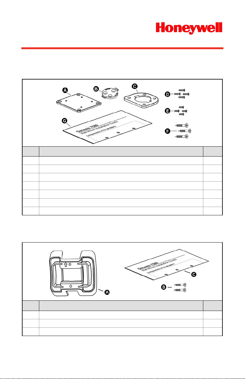
Genesis 7580
Item
Item Description
Qty
A
Adapter Plate
1 B Locking Plate
1
C
Base Cover
1 D M3 x .5 - 10 mm Flat Head Phillips Screw
4 E M3 x .5 - 8 mm Flat Head Phillips Screw
4 F #7 x 1.00" FHP Wood Screw
3
G
7580 Wall Mount Installation Guide
1
Item
Item Description
Qty
A
Wall Mount
1 B #7 x 1.00" FHP Wood Screw
2
C
7580 Wall Mount Installation Guide
1
Wall Mount Installation Guide
Components of Kit 46-00911
Figure 1
Components of Kit 46-00913
.
.
- 1 -
Figure 2
Page 2
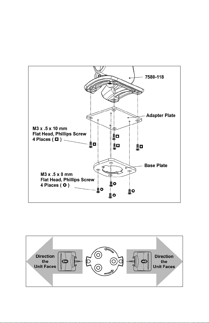
Adapter Kit Installation – Kit 46-00911
1. Remove the rubber feet on the bottom of the 7580.
2. Attach the adapter plate to the bottom of the unit with the four
M3 x .5 x 10 mm screws ( ) provided in the kit.
3. Attach the base plate to the adapter plate with the four M3 x .5 x 8 mm
screws ( ) provided in the kit.
Figure 3
4. Before mounting the locking plate, consider the position the unit will rest
when fully installed. There are two tabs located on the locking plate.
These tabs indicate the two directions the unit may face when locked into
position (see figure below).
Figure 4
- 2 -
Page 3

5. Use the template in Figure 1 or t he locking plate as a guide to drill three
A = #39 Drill, 3 Places
#39 pilot holes in the mounting surf ace.
6. Secure the locking plate to the wall with the three #7 wood screws ()
provided in the kit.
Figure 5
7. Position the unit so the base plate sit s flush over the locking plate.
Twist the unit 90° counter-clockwise to lock the unit into place.
Figure 6
Locking Plate Drill Template – Kit 46-00911
- 3 -
Figure 7
Page 4

Wall Mount Installation – Kit 46-00913
- 4 -
1. Drill two #39 pilot holes in the mounting surface. The pilot holes should be
centered vertically 44 mm apart .
2. Position the wall mount over the pilot holes with the arrow pointing up.
3. Secure the wall mount to the wall with the two #7 wood screws () provided
in the kit.
Figure 8
4. Slide the unit's base under the upper corner tabs on the wall mount.
5. Slide the remainder of the base in and down behind the lower corner tabs.
Figure 9
© 2007-2013 Honeywell International Inc. All rights reserved.
- 4 -
00-05250 Rev E
4/13
 Loading...