

Page 1

Stratos™ 2700
Bioptic Scanner/Scale
User’s Guide
Page 2

Disclaimer
Honeywell International Inc. (“HII”) reserves the right to make changes in specifications and other information contained in this document without prior notice, and the reader should in all cases consult HII to
determine whether any such changes have been made. The information in this publication does not represent a commitment on the part of HII.
HII shall not be liable for technical or editorial errors or omissions contained herein; nor for incidental or
consequential damages resulting from the furnishing, performance, or use of this material.
This document contains proprietary information that is protected by copyright. All rights are reserved.
No part of this document may be photocopied, reproduced, or translated into another language without
the prior written consent of HII.
2012-2014 Honeywell International Inc. All rights reserved.
Checkpoint® is a registered trademark of Checkpoint Systems, Inc.
Sensormatic® is a registered trademark of Tyco Retail Solutions.
Other product names or marks mentioned in this document may be trademarks or registered trademarks
of other companies and are the property of their respective owners.
Web Address: www.honeywellaidc.com
Page 3

Product Agency Compliance
USA
FCC Part 15 Subpart B Class A
This device complies with part 15 of the FCC Rules. Operation is subject to the following two conditions:
1. This device may not cause harmful interference.
2. This device must accept any interference received, including interference that may cause undesired operation.
This equipment has been tested and found to comply with the limits for a Class A digital device, pursuant to part 15 of the
FCC Rules. These limits are designed to provide reasonable protection against harmful interference when the equipment
is operated in a commercial environment. This equipment generates, uses, and can radiate radio frequency energy and, if
not installed and used in accordance with the instruction manual, may cause harmful interference to radio communications.
Operation of this equipment in a residential area is likely to cause harmful interference, in which case the user will be
required to correct the interference at his own expense.
Use only shielded data cables with this system.
Caution: Any changes or modifications made to this equipment not expressly approved by Honeywell may void the FCC
authorization to operate this equipment.
TÜV R Statement
TÜV R listed: UL 60950-1, Second Edition and CSA C22.2 No.60950-1-07, Second Edition.
Canada
Industry Canada ICES-003
This Class A digital apparatus complies with Canadian ICES-003. Operation is subject to the following conditions:
1. This device may not cause harmful interference.
2. This device must accept any interference received, including interference that may cause undesired operation.
Conformité à la règlementation canadienne
Cet appareil numérique de la Classe A est conforme à la norme NMB-003 du Canada. Son fonctionnement est assujetti
aux conditions suivantes :
1. Cet appareil ne doit pas causer de brouillage préjudiciable.
2. Cet appareil doit pouvoir accepter tout brouillage reçu, y compris le brouillage pouvant causer un fonctionnement
indésirable.
Normes TÜV R
Homologué TÜV R : UL 60950-1, seconde édition et CSA C22.2 No. 60950-1-07, seconde édition.
Europe
The CE marking indicates compliance to 2004/108/EC EMC Directive with Standards EN55022 CLASS B, EN55024,
EN61000-3-2, EN61000-3-3, and 2011/65/EU RoHS directive. In addition, complies to 2006/95/EC Low Voltage Directive, when shipped with recommended power supply. European contact:
Honeywell International Inc. shall not be liable for use of our product with equipment (i.e., power supplies, personal computers, etc.) that is not CE marked and does not comply with the Low Voltage Directive.
Waste Electrical and Electronic Equipment Information
Honeywell complies with Directive 2002/96/EC OF THE EUROPEAN PARLIAMENT AND OF THE COUNCIL of 27 January
2003 on waste electrical and electronic equipment (WEEE).
Hand Held Products Europe B.V.
Nijverheidsweg 9-13
5627 BT Eindhoven
The Netherlands
Page 4

This product has required the extraction and use of natural resources for its production. It may contain hazardous sub-
LASER LIGHT. DO NOT STARE INTO BEAM
CLASS 1 LASER PRODUCT
IEC60825-1: 2007 (ed 2)
Complies with 21 CFR 1040.10 and 1040.11
except for deviations pursuant to Laser
Notice No. 50, dated June 24, 2007.
stances that could impact health and the environment, if not properly disposed.
In order to avoid the dissemination of those substances in our environment and to diminish the pressure on the natural
resources, we encourage you to use the appropriate take-back systems for product disposal. Those systems will reuse or
recycle most of the materials of the product you are disposing in a sound way.
The crossed out wheeled bin symbol informs you that the product should not be disposed of along with municipal
waste and invites you to use the appropriate separate take-back systems for product disposal.
If you need more information on the collection, reuse, and recycling systems, contact your local or regional waste adminis-
tration.
You may also contact your supplier for more information on the environmental performances of this product.
Australia/NZ
C-Tick Statement
Conforms to AS/NZS 3548 EMC requirement
Japan
VCCI: 2012-04 Class A
Russia
Gost-R certificate
South Korea
This product meets Korean agency approval.
International
LED Safety Statement
LEDs have been tested and classified as “EXEMPT RISK GROUP” to the standard: IEC 62471:2006.
CB Scheme
Certified to CB Scheme IEC 60950-1, Second Edition.
Laser Safety Statement
This device has been tested in accordance with and complies with IEC60825-1 ed2 (2007). Complies with 21 CFR 1040.10
and 1040.11, except for deviations pursuant to Laser Notice No. 50, dated June 24, 2007.
Page 5
LASER LIGHT, DO NOT STARE INTO BEAM, CLASS 1 LASER PRODUCT.
!
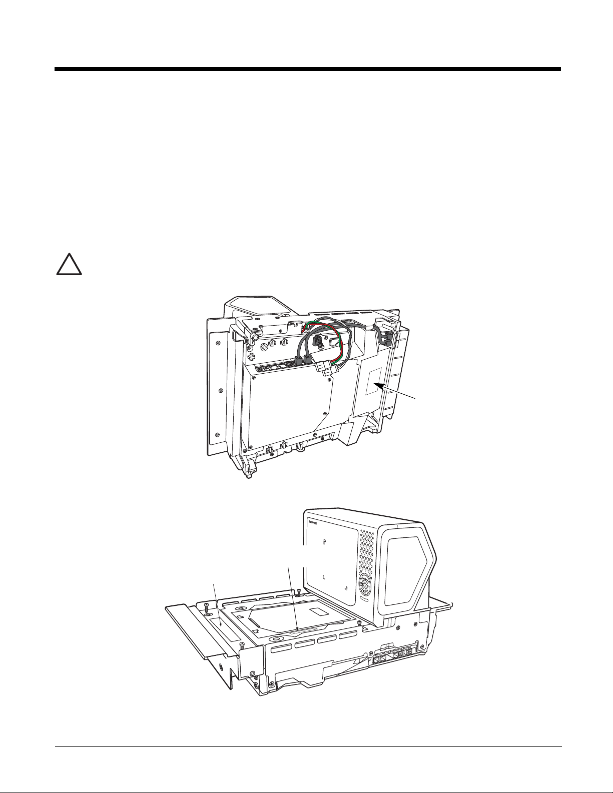
Compliance label location
Part Number, Model Number,
and Serial Number location
Scale Information
Caution: Use of controls or adjustments or performance of procedures other than those specified herein may
result in hazardous radiation exposure.
Patents
For patent information, refer to www.honeywellaidc.com/patents.
Solids and Water Protection
The Stratos 2700 has a rating of IP42, immunity of foreign particles and dripping water.
Warning
To reduce the possibility of heat-related injuries, avoid touching sections of the scanner that feel warm.
Required Safety Labels
(Internal)
Scale Display In
(Internal)
Scale Com In
AUX USB In
EAS Interlock
Aux RS232 In
Camera
+12V Out
Camera
Video In
Page 6

Page 7

Table of Contents
Chapter 1 - Getting Started
About This Manual ...............................................................................................................1-1
Printing Single Bar Codes....................................................................................................1-1
Dimensions ..........................................................................................................................1-1
Site Requirements ...............................................................................................................1-1
Vertical Clearance..........................................................................................................1-1
Ventilation and Spacing .................................................................................................1-1
Lighting...........................................................................................................................1-1
Service Access...............................................................................................................1-1
Power Installation...........................................................................................................1-2
EAS Considerations.......................................................................................................1-2
Power from Host ............................................................................................................1-2
Unpacking Your Device .......................................................................................................1-2
Configuring the 2700............................................................................................................1-2
Features of the Stratos Bioptic.............................................................................................1-3
Audible and Visual Indicators...............................................................................................1-3
Push Button Functionality ....................................................................................................1-4
LCD Diagnostic Display .......................................................................................................1-5
LCD Video Display...............................................................................................................1-5
Reading Techniques ............................................................................................................1-5
Chapter 2 - Installation
Installation Diagrams ...........................................................................................................2-1
Stratos 2751 Product Dimensions..................................................................................2-1
Stratos 2751 Installation Dimensions.............................................................................2-2
Stratos 2752 Product Dimensions..................................................................................2-3
Stratos 2752 Installation Dimensions.............................................................................2-4
Stratos 2753 Product Dimensions..................................................................................2-5
Stratos 2753 2 Point Installation Dimensions.................................................................2-6
Stratos 2753 3 Point Installation Dimensions.................................................................2-7
Stratos 2753 Bottom View..............................................................................................2-8
Installing the Stratos Bioptic.................................................................................................2-8
Device Ports...................................................................................................................2-8
Placing the Stratos Bioptic in the Check Stand..............................................................2-9
Place the Platter...........................................................................................................2-11
Adjust the Height..........................................................................................................2-11
Leveling........................................................................................................................2-12
Pole Display (if included)..............................................................................................2-13
Connecting an LCD Video Display.....................................................................................2-13
Connecting EAS.................................................................................................................2-14
Checkpoint®.................................................................................................................2-14
Sensormatic®...............................................................................................................2-14
Connecting to the POS System .........................................................................................2-14
i
Page 8

Chapter 3 - Programming the Bioptic Scanner Interface
Introduction..........................................................................................................................3-1
Printing Single Bar Codes ................................................................................................... 3-1
Menu Bar Code Security Settings ....................................................................................... 3-1
Setting Custom Defaults......................................................................................................3-1
Resetting the Custom Defaults............................................................................................3-2
Programming the Scanner Interface - Plug and Play .......................................................... 3-2
RS232 Serial Port Interface.................................................................................................3-2
RS232 OPOS Scanner Only - Dual Cable.....................................................................3-2
USB Interface ......................................................................................................................3-3
USB PC or Macintosh Keyboard ................................................................................... 3-3
USB HID ........................................................................................................................3-3
USB Serial Commands..................................................................................................3-4
USB Host Power............................................................................................................ 3-5
Host System Plug and Play Codes......................................................................................3-6
RS485............................................................................................................................ 3-6
IBM 46XX - Scanner Only..............................................................................................3-7
IBM Port 17 Interface - Scanner Only............................................................................ 3-7
RS485 Packet Mode......................................................................................................3-7
USB - IBM SurePos....................................................................................................... 3-8
NCR Host System Scanner Only - Dual Cable..............................................................3-8
Verifone
Gilbarco
Wincor Nixdorf Terminal Default Settings......................................................................3-9
Wincor Nixdorf Beetle™ Terminal Default Settings..................................................... 3-10
Keyboard Country Layout..................................................................................................3-10
Keyboard Style ..................................................................................................................3-20
Keyboard Conversion........................................................................................................ 3-21
Keyboard Modifiers............................................................................................................3-22
RS232 Baud Rate..............................................................................................................3-24
RS232 Word Length: Data Bits, Stop Bits, and Parity....................................................... 3-25
RS232 Receiver Timeout .................................................................................................. 3-27
RS232 Handshaking..........................................................................................................3-27
RS232 Timeout............................................................................................................ 3-29
Host Communications Timeout Beeper....................................................................... 3-29
XON/XOFF ..................................................................................................................3-29
ACK/NAK.....................................................................................................................3-30
NAK Retries................................................................................................................. 3-31
Support BEL/CAN in ACK/NAK ...................................................................................3-31
RS232 Defaults............................................................................................................3-32
®
Ruby Terminal Default Settings .................................................................... 3-9
®
Terminal Default Settings..............................................................................3-9
ii
Page 9

NCR Modifiers ...................................................................................................................3-32
NCR ACK/NAK ............................................................................................................ 3-32
NCR Modes ................................................................................................................. 3-32
Block Check Character................................................................................................ 3-34
NCR Prefix...................................................................................................................3-34
NCR Suffix................................................................................................................... 3-34
NCR NOF (Not-on-File) Error ...................................................................................... 3-34
Do Not Wait for NCR Weight .......................................................................................3-35
NCR Weight Timeout...................................................................................................3-35
Chapter 4 - Input/Output Settings
Power Up Settings...............................................................................................................4-1
Wake Activation.............................................................................................................4-1
Power Save Mode .........................................................................................................4-1
Power Up Beeper ..........................................................................................................4-4
Button Controls....................................................................................................................4-4
Button Click....................................................................................................................4-4
F1 Programmable Button...............................................................................................4-4
Sound Button................................................................................................................. 4-5
Image Capture Button....................................................................................................4-7
Beep on BEL Character.......................................................................................................4-8
Good Read Indicators..........................................................................................................4-8
Beeper – Good Read.....................................................................................................4-8
Beeper - Transmit Order................................................................................................4-9
Beeper Volume – Good Read........................................................................................4-9
Beeper Pitch – Good Read............................................................................................ 4-9
Beeper Duration – Good Read ....................................................................................4-10
Number of Beeps – Good Read ..................................................................................4-10
Beep on EAS Deactivation .......................................................................................... 4-11
Error Indicators.................................................................................................................. 4-11
Beeper Pitch – Error ....................................................................................................4-11
Number of Beeps/LED Flashes – Error .......................................................................4-12
LED Settings......................................................................................................................4-12
Disabled Scanner LED Flash.......................................................................................4-12
Bar Code Scanning Delays ............................................................................................... 4-12
Reread Delay...............................................................................................................4-12
User-Specified Reread Delay ......................................................................................4-13
2D Reread Delay .........................................................................................................4-13
Same Symbol Test ......................................................................................................4-14
Bar Code Absence Detection ......................................................................................4-14
Character Activation Mode ................................................................................................ 4-15
Activation Character ....................................................................................................4-15
End Character Activation After Good Read................................................................. 4-15
Character Activation Laser Timeout ............................................................................4-16
Character Deactivation Mode ............................................................................................4-16
Deactivation Character ................................................................................................4-16
iii
Page 10

Output Sequence Overview...............................................................................................4-16
Require Output Sequence ...........................................................................................4-16
Output Sequence Editor ..............................................................................................4-17
To Add an Output Sequence .......................................................................................4-17
Other Programming Selections....................................................................................4-17
Output Sequence Editor ..............................................................................................4-18
Sequence Timeout.......................................................................................................4-18
Sequence Match Beeper .............................................................................................4-19
Partial Sequence .........................................................................................................4-19
Require Output Sequence ...........................................................................................4-19
No Read ............................................................................................................................ 4-20
Chapter 5 - Programming an Auxiliary Scanner
Introduction..........................................................................................................................5-1
Scanner to Bioptic Communication ..................................................................................... 5-1
Scanner-Bioptic Packet Mode .......................................................................................5-1
ACK/NAK.......................................................................................................................5-1
Communication Timeout................................................................................................ 5-1
Aux Port Configuration Codes.............................................................................................5-2
Honeywell Scanner Aux Port Configuration...................................................................5-2
Datalogic™ Magellan
NCR Bioptic Aux Port Configuration.............................................................................. 5-2
Wincor Nixdorf Beetle Aux Port Configuration...............................................................5-2
Good Read Beep - Aux Scanner......................................................................................... 5-2
Aux Scanner D/E Commands..............................................................................................5-3
Reread Delay Override........................................................................................................5-3
®
Aux Port Configuration ............................................................. 5-2
Chapter 6 - Scale
Programming the Scale Interface ........................................................................................6-1
RS232............................................................................................................................6-1
RS485............................................................................................................................6-2
USB ...............................................................................................................................6-2
Scale Status Bytes ..............................................................................................................6-3
Scale Type...........................................................................................................................6-3
Scale Calibration ................................................................................................................. 6-4
Tools Required .............................................................................................................6-4
Priming the Scale for Calibration ..................................................................................6-4
Scale Calibration............................................................................................................6-5
Putting the Scale into Service Mode.............................................................................. 6-5
Scale Calibration with Remote Display..........................................................................6-5
Scale Calibration without Remote Display.....................................................................6-7
Scale Calibration with Push Buttons..............................................................................6-9
Calibration Verification.......................................................................................................6-10
Shift Test .....................................................................................................................6-11
Decreasing Load Test .................................................................................................6-11
Return to Zero Test......................................................................................................6-12
Security Seal Installation ................................................................................................... 6-12
iv
Page 11

Chapter 7 - Data Editing
Prefix/Suffix Overview ......................................................................................................... 7-1
To Add a Prefix or Suffix:............................................................................................... 7-1
To Clear One or All Prefixes or Suffixes........................................................................ 7-2
To Add a Carriage Return Suffix to All Symbologies..................................................... 7-2
Prefix Selections..................................................................................................................7-2
Suffix Selections.................................................................................................................. 7-3
Cash Register Code IDs......................................................................................................7-3
Function Code Transmit ...................................................................................................... 7-4
Communication Check Character........................................................................................ 7-4
Intercharacter, Interfunction, and Intermessage Delays......................................................7-5
Intercharacter Delay ......................................................................................................7-5
User Specified Intercharacter Delay.............................................................................. 7-5
Interfunction Delay.........................................................................................................7-6
Intermessage Delay....................................................................................................... 7-6
Chapter 8 - Data Formatting
Data Format Editor Introduction .......................................................................................... 8-1
Add a Data Format .............................................................................................................. 8-1
Other Programming Selections......................................................................................8-2
Terminal ID Table................................................................................................................ 8-3
Data Format Editor Commands...........................................................................................8-3
Move Commands...........................................................................................................8-6
Search Commands........................................................................................................ 8-7
Miscellaneous Commands.............................................................................................8-9
Data Formatter ..................................................................................................................8-11
Data Format Non-Match Error Tone............................................................................ 8-12
Primary/Alternate Data Formats........................................................................................8-13
Single Scan Data Format Change............................................................................... 8-13
Chapter 9 - Symbologies
All Symbologies................................................................................................................... 9-1
Message Length Description...............................................................................................9-1
Codabar...............................................................................................................................9-2
Codabar Concatenation................................................................................................. 9-3
Code 39 ............................................................................................................................... 9-5
Code 32 Pharmaceutical (PARAF)................................................................................ 9-6
Full ASCII....................................................................................................................... 9-7
Code 39 Code Page ......................................................................................................9-7
Interleaved 2 of 5.................................................................................................................9-8
NEC 2 of 5......................................................................................................................... 9-10
Code 93 ............................................................................................................................. 9-12
Code 93 Code Page ....................................................................................................9-13
Straight 2 of 5 Industrial (three-bar start/stop)...................................................................9-13
Straight 2 of 5 IATA (two-bar start/stop)............................................................................9-14
Matrix 2 of 5.......................................................................................................................9-15
v
Page 12

Code 11 ............................................................................................................................. 9-17
Code 128........................................................................................................................... 9-19
Code 128 Code Page ..................................................................................................9-20
ISBT 128............................................................................................................................9-20
GS1-128 ............................................................................................................................9-26
Telepen..............................................................................................................................9-28
UPC-A ...............................................................................................................................9-29
UPC-A/EAN-13
with Extended Coupon Code .......................................................................................... 9-32
UPC-A Number System 4 Addenda Required............................................................. 9-32
UPC-A Number System 5 Addenda Required............................................................. 9-33
Coupon GS1 DataBar Output............................................................................................9-35
In-Store Printed Bar Codes ............................................................................................... 9-35
Stitching.......................................................................................................................9-35
Framing........................................................................................................................9-35
Redundancy................................................................................................................. 9-36
UPC/EAN Security.............................................................................................................9-36
UPC-E0 .............................................................................................................................9-37
EAN/JAN-13 ......................................................................................................................9-41
Convert UPC-A to EAN-13 ..........................................................................................9-41
EAN-13 Beginning with 2 Addenda Required.............................................................. 9-42
EAN-13 Beginning with 290 Addenda Required.......................................................... 9-43
EAN-13 Beginning with 378/379 Addenda Required................................................... 9-43
EAN-13 Beginning with 414/419 Addenda Required................................................... 9-44
EAN-13 Beginning with 434/439 Addenda Required................................................... 9-45
EAN-13 Beginning with 977 Addenda Required.......................................................... 9-45
EAN-13 Beginning with 978 Addenda Required.......................................................... 9-46
EAN-13 Beginning with 979 Addenda Required.......................................................... 9-46
ISBN Translate ............................................................................................................9-48
ISSN Translate ............................................................................................................9-49
EAN/JAN-8 ........................................................................................................................ 9-50
MSI ....................................................................................................................................9-53
Plessey Code ....................................................................................................................9-55
GS1 DataBar Omnidirectional ........................................................................................... 9-57
GS1 DataBar Limited.........................................................................................................9-57
GS1 DataBar Expanded.................................................................................................... 9-58
Coupon Code Settings ...................................................................................................... 9-59
GS1 DataBar Expanded Coupons With AI (8110)....................................................... 9-59
GS1 DataBar Expanded Coupons Without AI (8110).................................................. 9-60
GS1 DataBar Expanded Coupon Preferred Mode.......................................................9-60
Coupon GS1 DataBar Output...................................................................................... 9-60
In-Store Printed Bar Codes..........................................................................................9-61
Trioptic Code .....................................................................................................................9-62
Codablock A ......................................................................................................................9-62
Codablock F ...................................................................................................................... 9-63
PDF417 ............................................................................................................................. 9-64
MacroPDF417 ................................................................................................................... 9-64
MicroPDF417.....................................................................................................................9-65
vi
Page 13

GS1 Composite Codes......................................................................................................9-66
UPC/EAN Version........................................................................................................9-66
GS1 Emulation .................................................................................................................. 9-67
TCIF Linked Code 39 (TLC39) .......................................................................................... 9-68
QR Code............................................................................................................................9-68
Data Matrix ........................................................................................................................9-70
MaxiCode ..........................................................................................................................9-71
Aztec Code ........................................................................................................................ 9-72
Chinese Sensible (Han Xin) Code.....................................................................................9-73
Chapter 10 - EAS Settings
EAS Deactivation............................................................................................................... 10-1
Sensormatic.......................................................................................................................10-2
Detection Ranges ........................................................................................................10-2
Deactivation Ranges....................................................................................................10-2
Checkpoint.........................................................................................................................10-2
EAS Controller Settings............................................................................................... 10-2
Programming the EAS Interface........................................................................................ 10-3
EAS Controller................................................................................................................... 10-4
EAS Interface ....................................................................................................................10-5
EAS Mode of Operation.....................................................................................................10-5
EAS Interlocked Duration Timeout ..............................................................................10-6
EAS Tag Detection ............................................................................................................ 10-6
Chapter 11 - Interface Keys
Keyboard Function Relationships......................................................................................11-1
Supported Interface Keys ..................................................................................................11-3
Chapter 12 - Utilities
To Add a Test Code I.D. Prefix to All Symbologies...........................................................12-1
Show Software Revision.................................................................................................... 12-1
Show Data Format.............................................................................................................12-1
Test Menu..........................................................................................................................12-1
TotalFreedom ....................................................................................................................12-2
EZConfig-Scanning Introduction........................................................................................12-2
Installing EZConfig-Scanning from the Web................................................................ 12-2
Resetting the Factory Defaults .......................................................................................... 12-3
Chapter 13 - Serial Programming Commands
Conventions.......................................................................................................................13-1
Menu Command Syntax.................................................................................................... 13-1
Query Commands ............................................................................................................. 13-1
Responses................................................................................................................... 13-2
Menu Commands ..............................................................................................................13-3
vii
Page 14

Chapter 14 - Product Specifications
Stratos Bioptic Scanner/Scale Product Specifications ......................................................14-1
Depth of Field Charts.........................................................................................................14-2
Standard Connector Pinouts ............................................................................................. 14-3
Host - RS232 ...............................................................................................................14-3
Host - RS485 ...............................................................................................................14-3
Host - USB Type B ......................................................................................................14-3
Scale to Host - RS232 .................................................................................................14-4
Scanner to Scale - COMM........................................................................................... 14-4
Scale to Scanner - Display ..........................................................................................14-4
Scale Display............................................................................................................... 14-5
RS232 Auxiliary Scanner - Bioptic end........................................................................14-5
USB Auxiliary Scanner - Bioptic end ...........................................................................14-5
Chapter 15 - Maintenance
Repairs ..............................................................................................................................15-1
Maintenance...................................................................................................................... 15-1
Cleaning the Scanner ..................................................................................................15-1
Cleaning the Window................................................................................................... 15-1
Troubleshooting a Stratos Bioptic Scanner ....................................................................... 15-1
Diagnostic Indicator...........................................................................................................15-2
Error Codes .................................................................................................................15-3
Chapter 16 - Customer Support
Technical Assistance.........................................................................................................16-1
Appendix A - Reference Charts
Symbology Charts ...............................................................................................................A-1
Linear Symbologies .......................................................................................................A-1
2D Symbologies.............................................................................................................A-2
Postal Symbologies .......................................................................................................A-2
ASCII Conversion Chart (Code Page 1252)........................................................................A-3
Lower ASCII Reference Table.............................................................................................A-4
ISO 2022/ISO 646 Character Replacements ......................................................................A-7
Unicode Key Maps ............................................................................................................A-10
Appendix B - Auxiliary Honeywell Scanner Configuration Codes
RS-232 ................................................................................................................................B-1
USB Serial ...........................................................................................................................B-1
viii
Page 15

1
Getting Started
Honeywell’s Stratos™ bioptic scanner/scale incorporates a revolutionary hybrid platform that enables retailers to maximize customer throughput for rapid pass-through scanning of linear bar codes, plus area imaging technology for scanning of 2D and
mobile bar codes. The Stratos bioptic enhances the checkout scanning experience for traditional checkout lanes and self-checkout environments.
About This Manual
This User’s Guide provides installation and programming instructions for the Stratos bioptic. Product specifications, dimensions, warranty, and customer support information are also included.
Honeywell bar code scanners are factory programmed for the most common terminal and communications settings. If you need
to change these settings, programming is accomplished by scanning the bar codes in this guide.
An asterisk (*) next to an option indicates the default setting. See Serial Programming Commands beginning on page 13-1 for a
complete listing of the serial commands for programming bar codes.
Note: The Stratos bioptic is programmed via the vertical window only. The horizontal window intentionally does not read
programming bar codes as a means of preventing accidental scans.
Printing Single Bar Codes
If you wish to print single-page bar codes for any programming selection, hover your cursor over the bar code, and left click. A
document with that bar code on a single page is displayed. Click the Print button to print that page.
The bar code document contains all the programming bar codes from this manual. You can scroll through the pdf to locate any
other codes in which you are interested.
Dimensions
Site Requirements
Vertical Clearance
A minimum clearance height of 7 inches (17.78cm) from the checkout counter surface is needed for the vertical hood. For
further information, refer to Installation Diagrams beginning on page 2-1.
Ventilation and Spacing
The Stratos bioptic has a die-cast housing that dissipates heat, allowing the unit to operate without a ventilation fan. Honeywell recommends that the temperature surrounding the unit does not exceed 104°F (40°C). There should be adequate
convection and minimal heat producing equipment in close proximity of the unit. A cooling fan with a filter is recommended
if there will be a conveyor motor or other heat producing equipment close to the unit that will create a high temperature environment.
Adequate spacing between the unit and the checkout counter opening is required for proper operation of the scale. When
the Stratos bioptic is mounted properly, the scale platter should be able to move up and down freely without hitting the
edges of the checkout counter cutout. Refer to Installation beginning on page 2-1 for detailed cutout dimensions and
mounting instructions.
Lighting
The Stratos bioptic should not be pointed toward any strong light sources that would create glare on the vertical window.
Service Access
When routing and installing the cable(s) and power supply, make sure to leave access so that these components may be
swapped easily without the need to remove the unit from the checkout counter.
When calibrating or zeroing the scale, do not remove the unit from the checkout counter. Refer to Scale beginning on page
6-1 for detailed instructions on zeroing and calibration.
1 - 1
Page 16

Power Installation
The Power Supply (AC/DC) should be connected to an AC outlet that is free of electrical noise (clean). A qualified electrician can determine the amount of electrical noise on the AC line. All power supplies must be properly grounded.
Honeywell recommends using a switched AC outlet. The switch should be located on the operator's side of the checkout
counter in close proximity to the Stratos bioptic to facilitate calibration and service of the unit.
Note: The power supply should never be disconnected from the Stratos bioptic without first disconnecting the AC power.
EAS Considerations
Do not install any large iron fixtures, such as steel support poles, near the Stratos bioptic. Doing so may re-shape the EAS
tag deactivation field. See EAS Settings beginning on page 10-1 for complete EAS information.
Power from Host
The Stratos 2700 can be powered from a USB PlusPower host or other host system that can supply at least 12 Volts at
1.5Amps using special cables. (This is the typical voltage and current available on a Green USB Plus Power connector).
It may also be possible to connect and power an auxiliary scanner, a BOB camera, or other peripheral. Please consult with
a Honeywell representative to review plans to power these or other auxiliary devices when the unit will be powered from the
host. See USB Host Power on page 3-5 for power conservation settings.
Unpacking Your Device
After you open the shipping carton containing the product, take the following steps:
• Check for damage during shipment. Report damage immediately to the carrier who delivered the carton.
• Make sure the items in the carton match your order.
Save the shipping container for later storage or shipping.
1. Make sure the shipping box is top-side up before opening.
2. Carefully remove the platter and store it in a safe location until the unit is properly
installed into the checkout counter.
3. Remove all loose packing materials from the box.
4. Lift the Stratos bioptic out of the box by grasping each end of the unit and lifting directly
up.
Note: Do not remove the scanner from the box by grabbing the shipping foam. This can
result in the unit falling.
5. Remove the shipping foam from around the scanner.
Note: Retain all packing materials in the event you need to re-pack the unit.
6. Remove the protective film from the top side platter surface, vertical scan window, and horizontal scan window.
Configuring the 2700
If the unit has not already been pre-configured with the proper POS interface and selectable options, program the configuration
now. You may do so using EZConfig-Scanning (see EZConfig-Scanning Introduction on page 12-2), or by scanning the programming bar codes in this manual.
1 - 2
Page 17
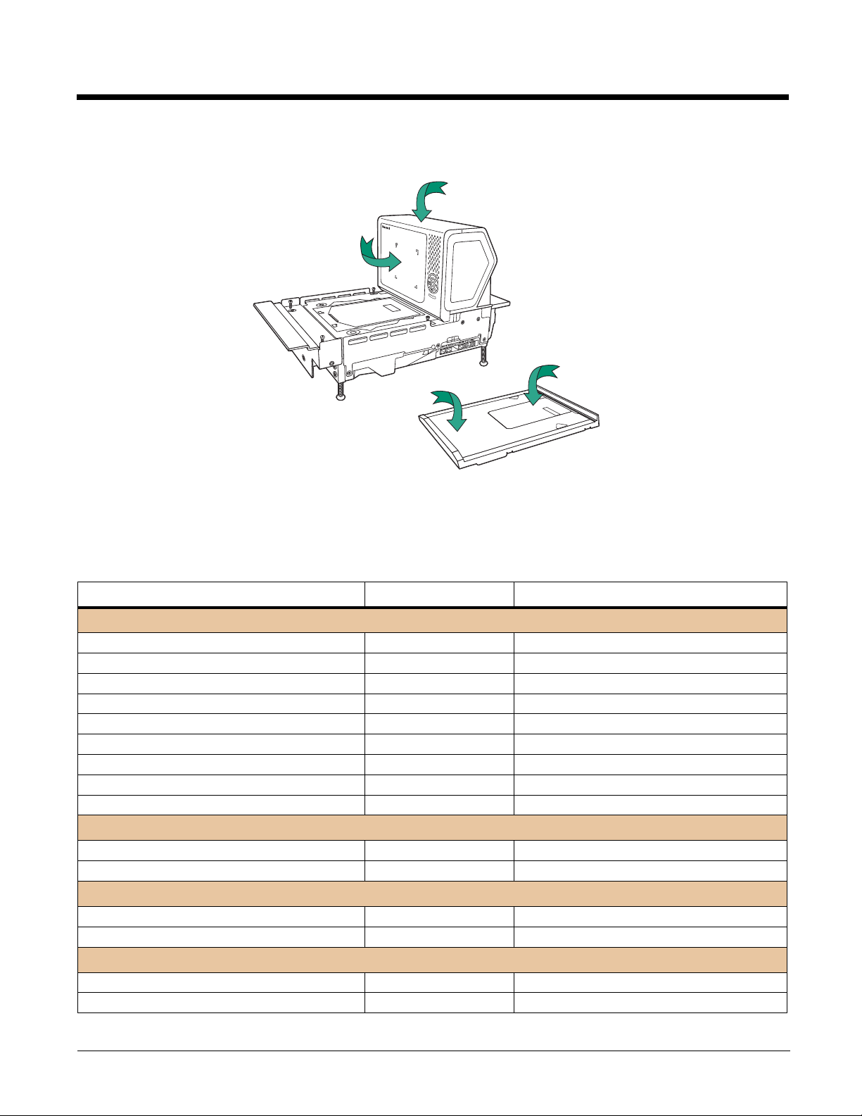
Features of the Stratos Bioptic
LED Indicators
Vertical
Scanning
Window
Horizontal
Scanning
Window
Platter
Audible and Visual Indicators
The Stratos bioptic provides audible tones and visual indicators that indicate the status of the unit. See Input/Output
Settings beginning on page 4-1 to change any of these settings. The following table lists the default audible and visual indica-
tions. See also Error Codes on page 15-3.
LEDs Sound Indication
Normal Operations
Blue Flash, then Green and Red
Green Continuous None Laser On
Green Flash Beep Good Scan
Green Flash Auxiliary Scanner Beep Good Scan from auxiliary scanner
Green/Blue Flash Beep Good Scan from RFID
Blue Flash Fast Beep EAS Deactivate
Red, then alternating Red and Green Razz or Beep
Alternating Red and Green Flashes None
Green and Red Continuous None
Power Management
Green Flash None Power Save - Lasers Off
Green Continuous None Power Save - Blinking Lasers
Scale
Yellow Continuous None Scale at Zero
Yellow Off None Scale at steady weight
Maintenance/Error
Green, Red, Yellow Flash Ascending Beep Bioptic Flash
Green, Red, Yellow Flash None Bioptic Configuration
Beep Power up
Not on File (NCR Protocol)
Scanner Software Disabled
Scanner Hardware Disabled
1 - 3
Page 18
LEDs (Continued) Sound Indication
Push Buttons
Green, Red, Yellow Flash Auxiliary Scanner Beep Auxiliary Scanner Configuration
Green, Red, Yellow Flash With or without Beep
Red Flash Razz Error Event - Minor (See Troubleshooting a
Red Flash, then Continuous Razz Error Event - Major (See Troubleshooting a
Green Flash Cuckoo Beep
Green Flash Ascending 3 Tone
Scale Calibration
Stratos Bioptic Scanner, beginning on page
15-1)
Stratos Bioptic Scanner, beginning on page
15-1)
Configuration Code - Temporary
Configuration Code - Permanent
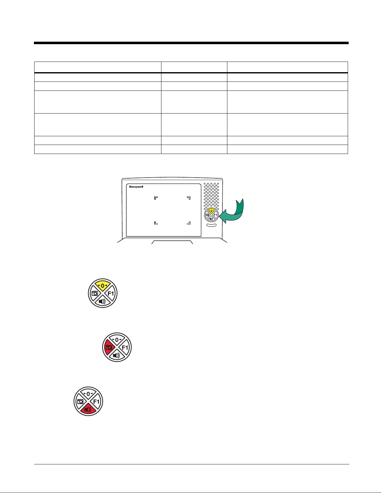
Push Button Functionality
There is a ring of 4 push buttons on the front of the device. The following is a brief description of the default settings for the push
buttons. For complete functionality and programming options, refer to Button Controls on page 4-4.
Note: Pressing the Sound button wakes the scanner from sleep mode.
Scale Zero
This button is normally lit when the scale is at zero. The backlight goes off when the scale is not at zero. Press this button
to reset the scale to zero.
Image Capture
Press this button once to scan a bar code using a customer-facing scanner (if installed). Push it a second time to disable
the customer-facing scanner. See Image Capture Button on page 4-7 for further information.
Sound
Press repeatedly to scroll through the beeper volumes. This button is also used to clear error conditions (LED lights,
beeps, and LCD notifications). Hold this button down for 5 seconds to put the scanner to sleep.
1 - 4
Page 19
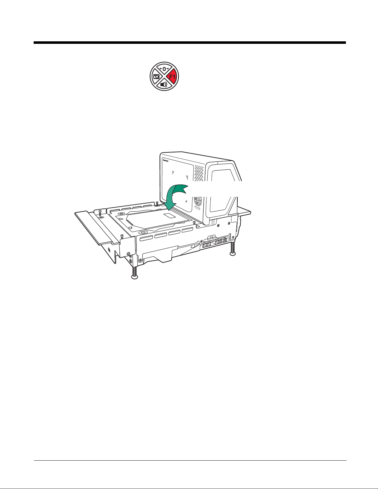
F1 Programmable Functions
LCD Diagnostic Display
Press this button once quickly to input a number of repeat scans. For example, if there are 6 cans, the cashier would scan
the first can, then push the F1 button 5 times quickly to indicate 5 more repeats of that scan. Press and hold the F1 button
for 5 seconds to deactivate an EAS tag. Refer to F1 Programmable Button (page 4-4) for further information about the F1
button settings.
LCD Diagnostic Display
There is an LCD diagnostic display located under the platter near the end of the scanner closest to the vertical window.
Refer to Diagnostic Indicator on page 15-2 for complete information about codes that appear in this display.
LCD Video Display
If you are using a VGA security camera, you can feed the video line to the Stratos bioptic. This type of camera could be used to
display items on the bottom of a cart, or to show activity at a deliveries door. See Connecting an LCD Video Display on page 213 for connection information for an external camera.
Reading Techniques
2D bar codes, such as drivers’ licenses or coupons on mobile phones, must be scanned using the vertical window. Linear bar
codes can be scanned using either the vertical or the horizontal window.
1 - 5
Page 20

1 - 6
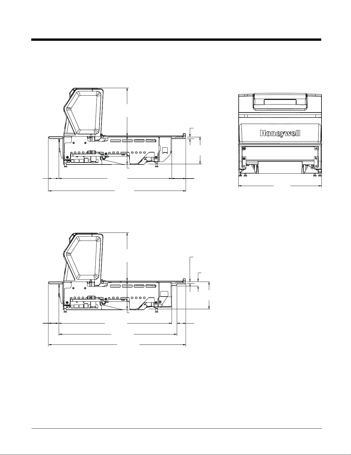
Page 21
2
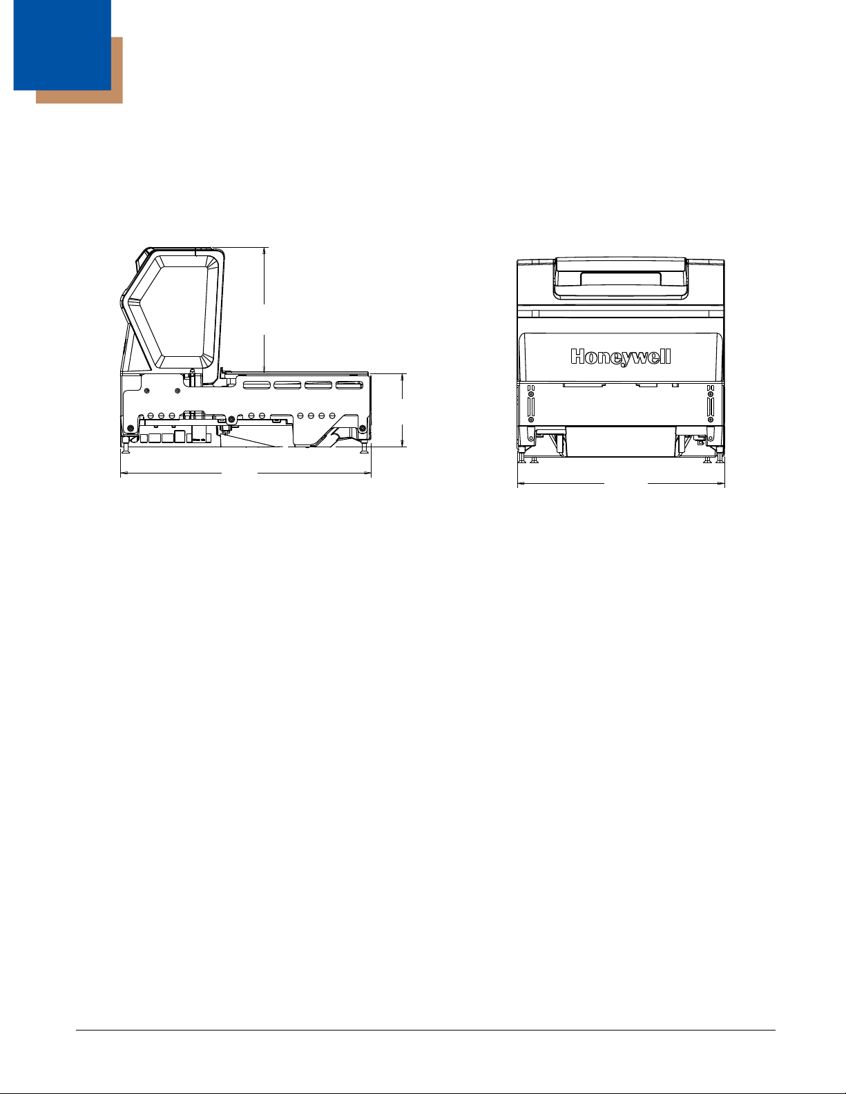
7 in.
178mm
4 in.
101.4mm
14 in.
353mm
11.5 in.
292mm
Installation
Installation Diagrams
Stratos 2751 Product Dimensions
2 - 1
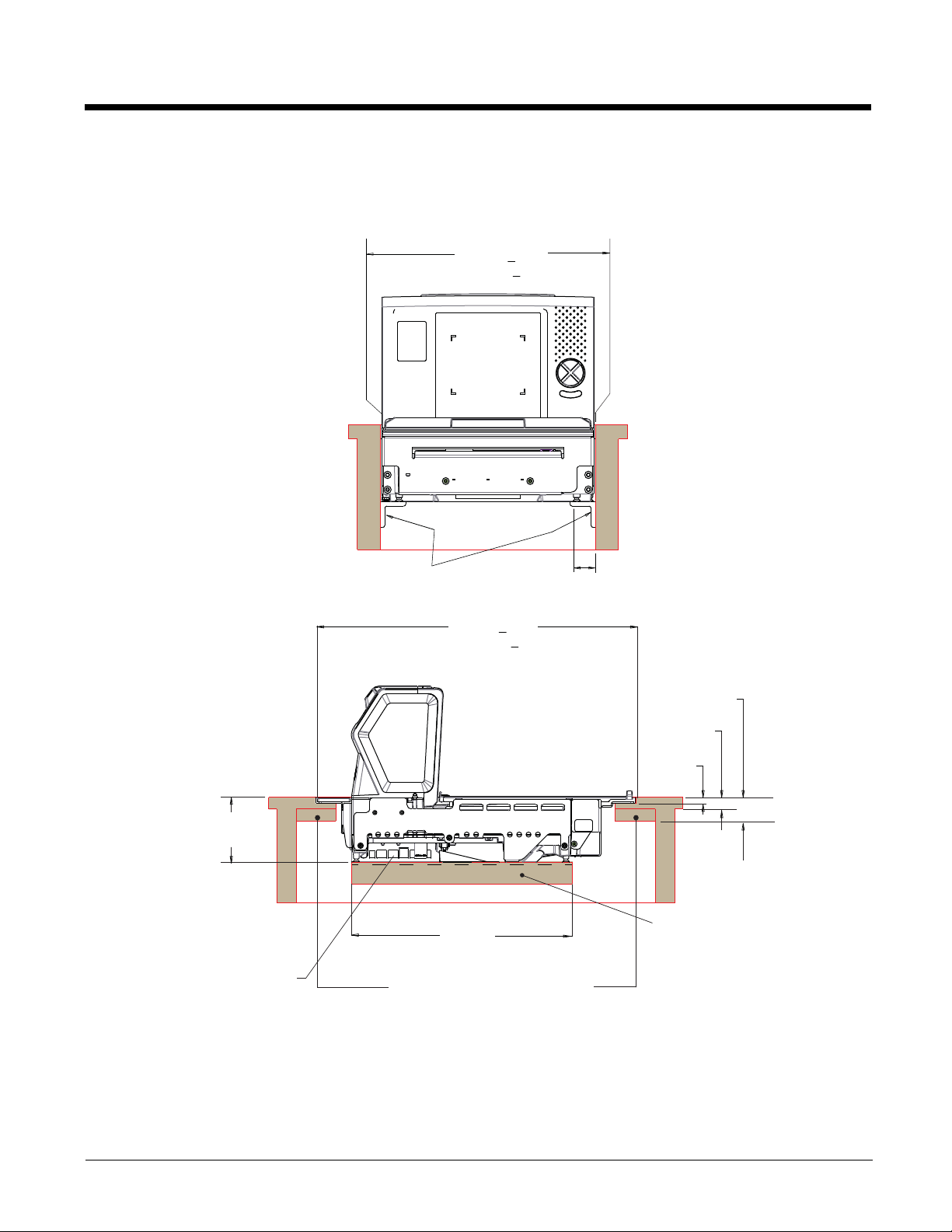
Page 22
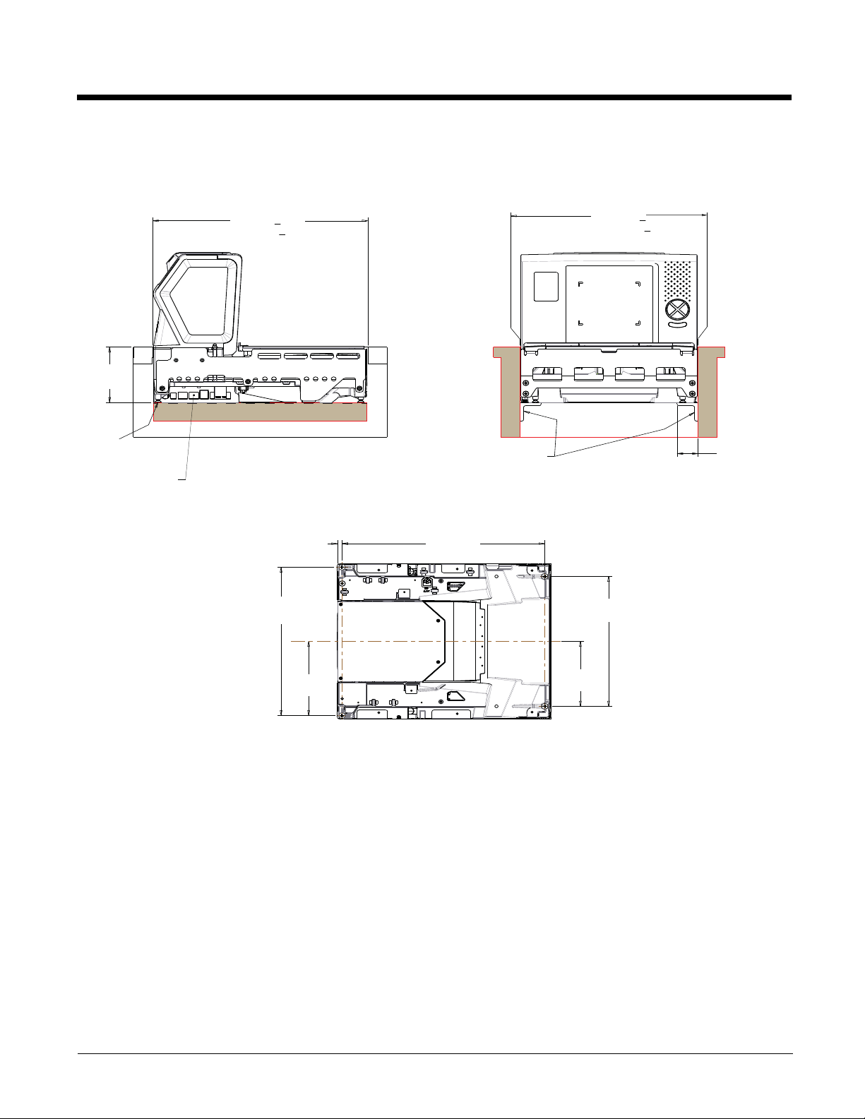
Stratos 2751 Installation Dimensions
Note: Cutout wall must not contact the platter.
4.1 in.
104.13mm
Leveling Feet
See Bottom View
Keep connector areas
free from obstructions
Cutout Length
14.023 in. + .062
356.18mm + 1.59
10.984 in.
279mm
.299 in.
7.58mm
13.228 in.
336mm
Support Brackets
Cutout Width
11.625 in. + .062
295.28mm + 1.59
9.606 in.
244mm
1.375 in.
34.93mm
Max Both Sides
5.492 in.
139.5mm
Bottom View
4.803 in.
122mm
Note: “L” brackets and other counter mounting hardware are not included with the Stratos 2700.
2 - 2
Page 23
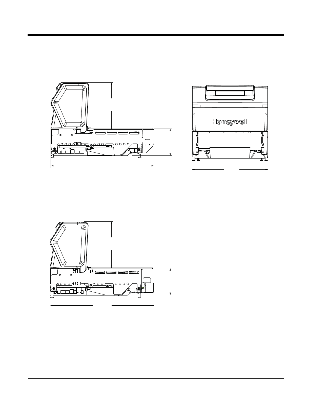
Stratos 2752 Product Dimensions
11.5 in.
292mm
7 in.
178mm
4 in.
101.4mm
15.7 in.
399mm
Stratos 2752 without scale:
Stratos 2752 with scale:
7 in.
178mm
4 in.
101.4mm
15.7 in.
399mm
2 - 3
Page 24
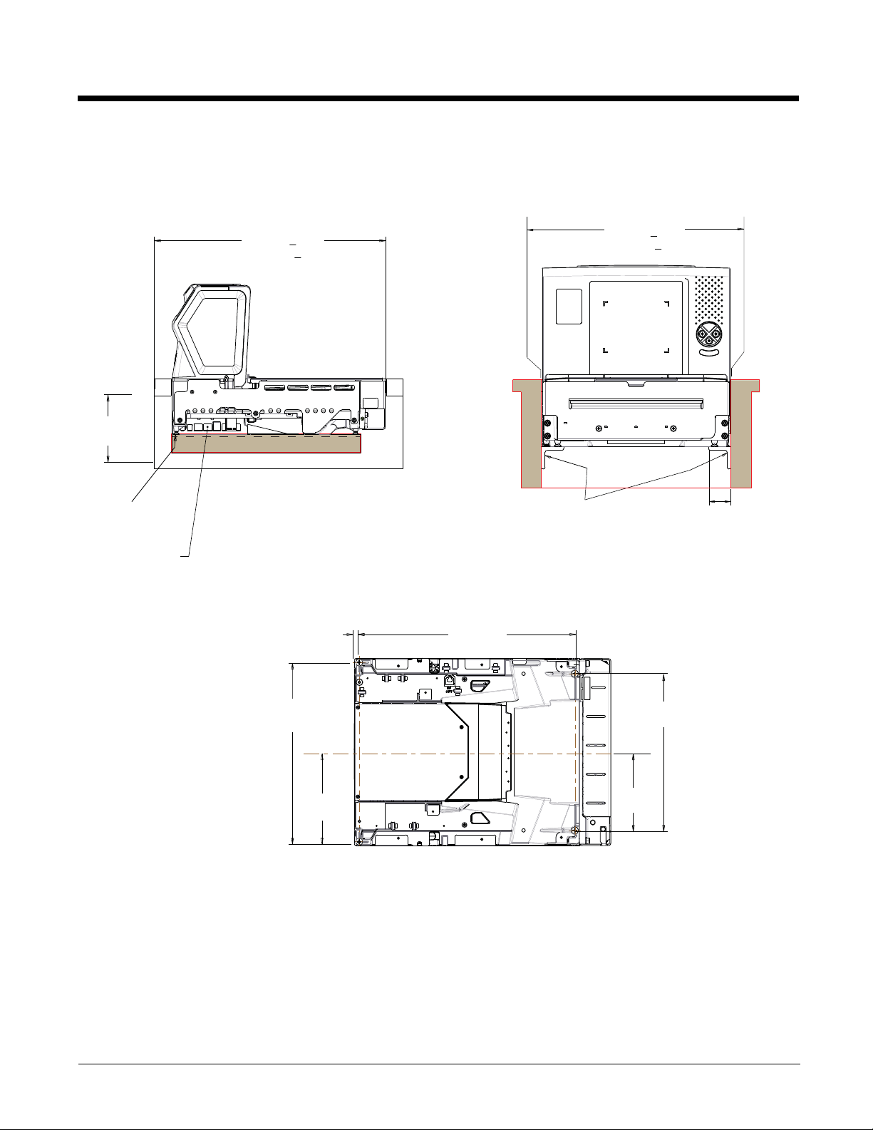
Stratos 2752 Installation Dimensions
Note: Cutout wall must not contact the platter.
4.1 in.
104.13mm
Leveling Feet
See Bottom View
Keep connector areas
free from obstructions
Cutout Length
15.834 in. + .062
402.18mm + 1.59
Support Brackets
Cutout Width
11.625 in.
+ .062
295.28mm + 1.59
1.375 in.
34.93mm
Max Both Sides
.299 in.
7.58mm
10.984 in.
279mm
5.492 in.
139.5mm
13.228 in.
336mm
4.803 in.
122mm
Bottom View
Note: “L” brackets and other counter mounting hardware are not included with the Stratos 2700.
9.606 in.
244mm
2 - 4
Page 25
Stratos 2753 Product Dimensions
Stratos 2753 without scale:
1.5 in.
38mm
16.4 in.
417.5mm
20 in.
508mm
Stratos 2753 with scale:
7 in.
178mm
4 in.
101.4mm
.3 in.
6.8mm
4 in.
101.4mm
2.1 in.
52.5mm
11.5 in.
292mm
1.5 in.
38.3mm
16.4 in.
416.3mm
17.1 in.
434.8mm
7 in.
178mm
4 in.
101.4mm
20 in.
508mm
.27 in.
6.9mm
.53 in.
13.4mm
4 in.
101.4mm
1.4 in.
34.5mm
2 - 5
Page 26

Stratos 2753 2 Point Installation Dimensions
Note: Cutout wall must not contact the platter.
Cutout Length
20.12 in. + .062
511.18mm + 1.59
Cutout Width
11.625 in.
+ .062
295.28mm + 1.59
Keep connector areas
free from obstructions
Additional structural support may be
required for thin countertops. 2 “L” brackets,
maximum length 11.25 in. (286mm) each,
may be used instead of a routed edge.
.367 in.
9.33mm
.750 in.
19.05mm
1.5 in.
38.1mm
1.25in.
31.75mm
1.25in.
31.75mm
.367 in.
9.33mm
.750 in.
19.05mm
1.5 in.
38.1mm
4.1 in.
104.13mm
2 - 6
Note: “L” brackets and other counter mounting hardware are not included with the Stratos 2700.
Page 27
Stratos 2753 3 Point Installation Dimensions
Note: Cutout wall must not contact the platter.
Keep connector areas
free from obstructions
Additional structural support may be
required for thin countertops. 2 “L” brackets,
maximum length 11.25 in. (286mm) each,
may be used instead of a routed edge.
.367 in.
9.33mm
.750 in.
19.05mm
1.5 in.
38.1mm
1.375 in.
34.93mm
Max Both Sides
Support Brackets
4.1 in.
104.13mm
Cutout Width
11.625 in.
+ .062
295.28mm + 1.59
Cutout Length
20.12 in. + .062
511.18mm + 1.59
Support brackets
13.94 in.
354mm
Note: “L” brackets and other counter mounting hardware are not included with the Stratos 2700.
2 - 7
Page 28
Stratos 2753 Bottom View
9.606 in.
244mm
4.803 in.
122mm
13.228 in.
336mm
.299 in.
7.58mm
5.492 in.
139.5mm
10.984 in.
279mm
Bottom View
(Internal)
Scale Display In
(Internal)
Scale Com In
Aux RS232 In EAS Interlock AUX USB In
Camera
Video In
Camera
+12V Out
Left Side Ports:
Camera Video In
Camera +12V Out (future use)
Aux RS232 In
EAS Interlock
Aux USB In
(Internal) Scale Com In
(Internal) Scale Display In
Scale Remote
Display
Scale RS232
to Host
Scanner
RS232 to Host
Scanner USB
to Host
DC
Power In
Right Side Ports:
Scale Remote Display
Scale RS232 to Host
Scanner RS232 to Host
Scanner USB to Host
DC Power In
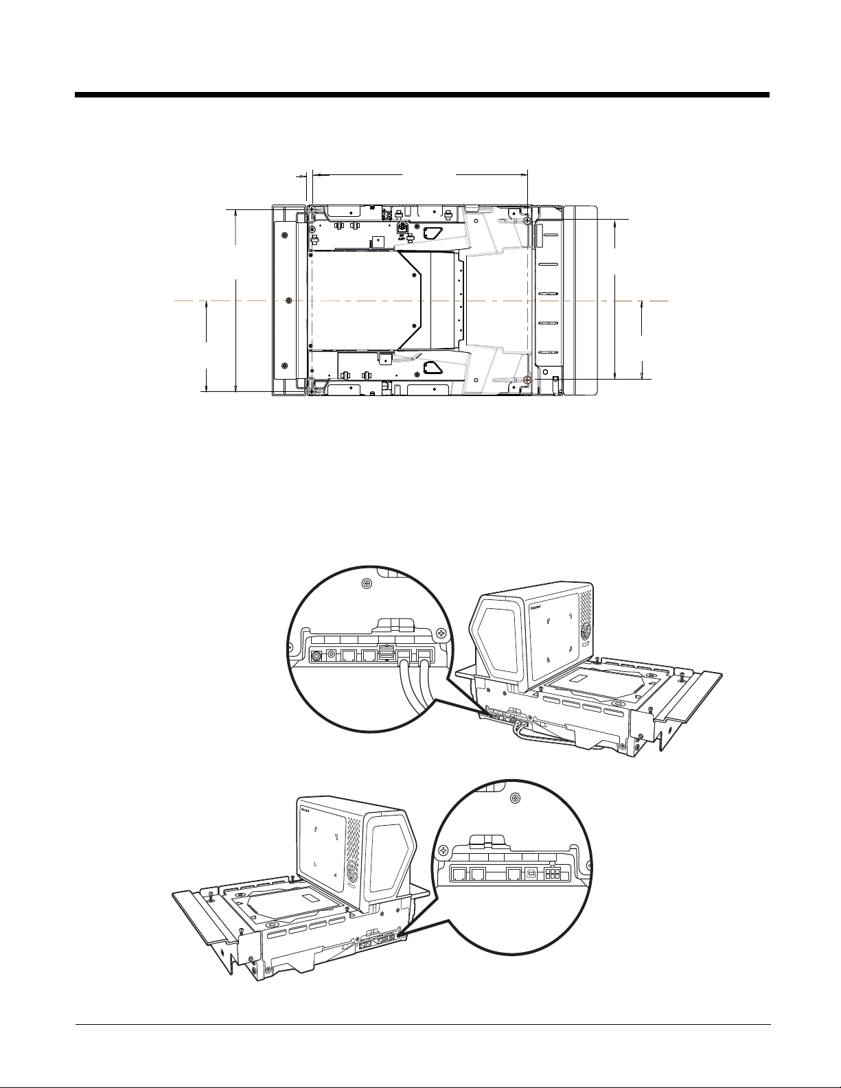
Installing the Stratos Bioptic
Step 1. Shut down the POS system.
Step 2. Connect the appropriate cables from the host system and auxiliaries to the ports on the 2700.
Device Ports
2 - 8
Camera
Video In
Camera
+12V Out
Aux RS232 In
EAS Interlock
AUX USB In
(Internal)
Scale Com In
(Internal)
Scale Display In
Page 29
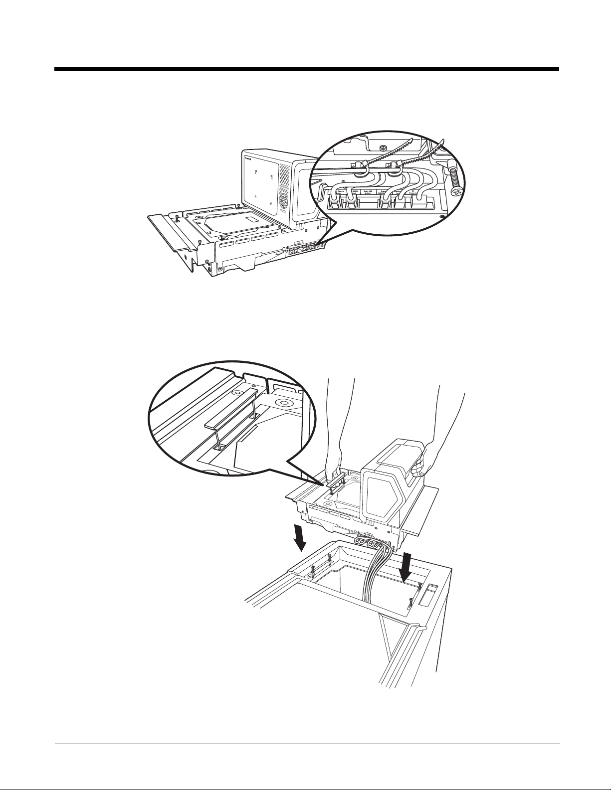
Step 3. Use cable ties to secure the cables to the sides so they won’t interfere with installation.
Note: Cable ties are not included with the Stratos 2700.
Placing the Stratos Bioptic in the Check Stand
Pull up the lift handle located in front of the horizontal window. Use this lift handle with one hand and grasp the 2700 underneath the vertical display with the other hand. Carefully lower the 2700 into the check stand cutout. Push the retractable
handle back in.
2 - 9
Page 30
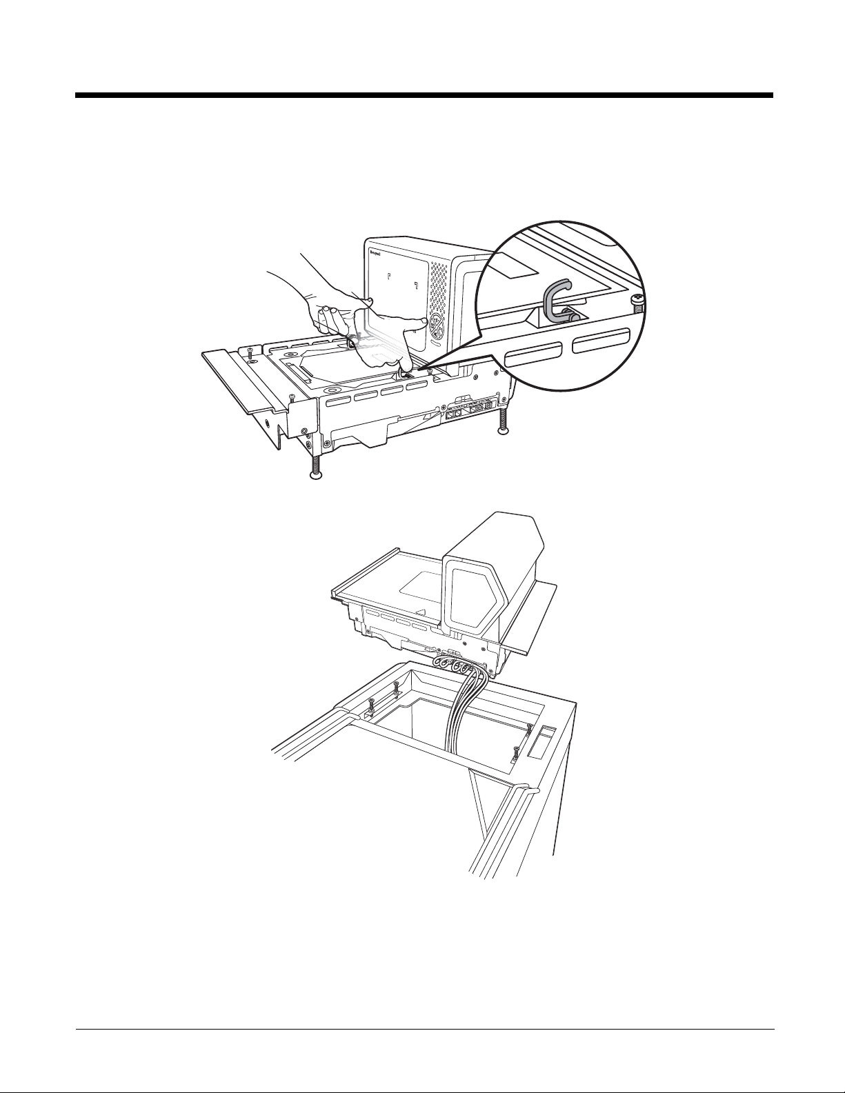
Alternate Lift Method
There are also two finger handles located near the base of the vertical window. Swing them up into position with your
index fingers. Hook both your index fingers into these handles and rest both thumbs against the vertical window frame
for added stability. Carefully lower the 2700 into the check stand cutout.
Step 4. Route the cables through the check stand cutout to the POS terminal.
Note: “L” brackets and other counter mounting hardware are not included with the Stratos 2700.
2 - 10
Page 31

Place the Platter
!
Place the platter in position over the horizontal window.
WARNING: Do not attempt to adjust the screws that support the platter. Any attempt to do so may throw
the scale out of calibration.
Adjust the Height
Make sure the platter is at the correct height and completely level. The front edge of the platter should be flush with the
check stand. To adjust the height, turn the leveling screws. If the model 2753 is installed, adjust the 4 leveling screws in the
check stand until the platter is at the correct height.
2 - 11
Page 32

Remove the platter and make sure the scanner is level both with and without the platter installed. For installations that do
Platter is below the counter edge
Platter is above the counter edge
Platter is even with the counter edge
Ideal Good Not Level
(if not rocking) (if not rocking)
not have hanging ledges, adjust the leveling feet at the bottom 4 corners of the scanner until the platter is at the correct
height.
Check the platter height by sliding an item across the check stand and the platter. If you feel it bump over the leading or
trailing edge, adjust the leveling screws until it passes over the platter smoothly. The center of the platter should be slightly
higher than the counter so that when an item is placed on the scale, the item’s edges do not rest on the counter.
Leveling
Press your hands on each corner of the platter and gently rock the opposite corners. If the platter rocks on any corner,
adjust the leveling screws. Check the bubble level beneath the platter. It should indicate when the 2700 is level.
2 - 12
Page 33

If the scale is not level, it may fall out of calibration and cannot be used. You must level it in order for it to perform properly.
(Internal)
Scale Display In
(Internal)
Scale Com In
Aux RS232 In EAS Interlock AUX USB In
Camera
Video In
Camera
+12V Out
Once the 2700 is at the correct height and level, lock down the leveling screws with the bolt at the bottom.
Pole Display (if included)
Step 1. Route the pole display cables through the pole opening (if pole display is included).
Step 2. Mount the pole display.
Connecting an LCD Video Display
You may install a VGA camera and position it to view the bottom of a shopping basket. Connect the yellow video line from the
camera to the port marked Camera Video In.
Camera
Video In
Camera
+12V Out
Aux RS232 In
EAS Interlock
AUX USB In
(Internal)
Scale Com In
(Internal)
Scale
Display In
2 - 13
Page 34

The images from the video camera are shown in the upper left corner of the scanner’s vertical tower.
(Internal)
Scale Display In
(Internal)
Scale Com In
Aux RS232 In
EAS Interlock
AUX USB In
Camera
Video In
Camera
+12V Out
Checkpoint EAS Antenna Port
Sensormatic
Antenna
Connectors
Connecting EAS
Checkpoint®
When connecting to a Checkpoint EAS system, connect the Checkpoint EAS interlock cable (if required) to the EAS interlock port on the left side of the 2700 (see Device Ports on page 2-8). Connect the Checkpoint antenna cable to the antenna
port on the underside of the 2700, shown above. Refer to EAS Settings beginning on page 10-1 for configuration codes
and further EAS programming information.
Sensormatic®
When connecting to a Sensormatic EAS system, connect the Sensormatic RS232 control line to the EAS interlock port on
the left side of the 2700 (see Device Ports on page 2-8). Connect the Sensormatic antenna cables to the to the multi-colored antenna connectors on the underside of the 2700, shown above. Contact Tyco for further information about Sensormatic installation and configuration. Refer to EAS Settings beginning on page 10-1 for Stratos bioptic configuration codes
and further EAS programming information.
Connecting to the POS System
Step 1. Turn off the host system.
Step 2. If using a single cable, plug one end of the interface cable into the port labeled for your interface on the right side
of the Stratos bioptic:
USB: Scanner USB to Host
RS232: Scanner RS232 to Host
RS485: Scanner RS232 to Host
When using a dual cable, plug an RS232 cable into the Scale to Host port on the right side of the Stratos bioptic.
2 - 14
Page 35

If using a USB Plus Power connection to the host (12V), match the turquoise cable connector to the turquoise
receptor on the 2700.
Step 3. Connect the other end of the interface cable to the appropriate communication port on the host's scale device.
Step 4. Plug the optional remote display cable into the port labeled ScaleRemote Display on the right side of the Stratos
bioptic.
Step 5. Plug the external power supply into the 3-pin socket labeled DC Power In on the right side of the Stratos bioptic.
Step 6. Connect AC power to the transformer. If the AC outlet is equipped with an on/off switch, turn the power on.
Step 7. Configure the Stratos bioptic to match the host system’s communication parameters. Refer to Programming the
Bioptic Scanner Interface beginning on page 3-1.
2 - 15
Page 36

2 - 16
Page 37

3
Set Custom Defaults
Save Custom Defaults
Programming the Bioptic Scanner Interface
Introduction
This chapter describes how to program the Stratos bioptic scanner for the desired interface. To program the scale interface,
refer to Programming the Scale Interface, beginning on page 6-1.
Printing Single Bar Codes
If you wish to print single-page bar codes for any programming selection, hover your cursor over the bar code, and left click. A
document with that bar code on a single page is displayed. Click the Print button to print that page.
The bar code document contains all the programming bar codes from this manual. You can scroll through the pdf to locate any
other codes in which you are interested.
Menu Bar Code Security Settings
Honeywell scanners are programmed by scanning menu bar codes or by sending serial commands to the scanner. If you want
to restrict the ability to scan menu codes, you can use the Menu Bar Code Security settings. Contact the nearest technical support office (see Technical Assistance on page 16-1) for further information.
Setting Custom Defaults
You have the ability to create a set of menu commands as your own, custom defaults. To do so, scan the Set Custom Defaults
bar code below before scanning the menu commands for your custom defaults. If a menu command requires scanning numeric
codes from the back cover, then a Save code, that entire sequence will be saved to your custom defaults. When you have
entered all the commands you want to save for your custom defaults, scan the Save Custom Defaults bar code.
You may have a series of custom settings and want to correct a single setting. To do so, just scan the new setting to overwrite
the old one. For example, if you had previously saved the setting for Beeper Volume at Low to your custom defaults, and decide
you want the beeper volume set to High, just scan the Set Custom Defaults bar code, then scan the Beeper Volume High
menu code, and then Save Custom Defaults. The rest of the custom defaults will remain, but the beeper volume setting will be
updated.
3 - 1
Page 38

Resetting the Custom Defaults
Activate Custom Defaults
RS232 Interface
If you want the custom default settings restored to your scanner, scan the Activate Custom Defaults bar code below. This is
the recommended default bar code for most users. It resets the scanner to the custom default settings. If there are no custom
defaults, it will reset the scanner to the factory default settings. Any settings that have not been specified through the custom
defaults will be defaulted to the factory default settings.
Programming the Scanner Interface - Plug and Play
Plug and Play bar codes provide instant scanner set up for commonly used interfaces. They are also used to program the scanner portion when using a dual cable interface.
Note: After you scan one of the codes, power cycle the scanner to have the interface in effect.
For scale and scanner/scale interfaces, refer to Programming the Scale Interface on page 6-1. For EAS Interfaces, refer to
Programming the EAS Interface on page 10-3.
RS232 Serial Port Interface
The RS232 Interface bar code is used when connecting to the serial port of a PC or terminal. The following RS232 Interface
bar code programs a carriage return (CR) and a line feed (LF) suffix, baud rate, and data format as indicated below.
Option Setting
Baud Rate 9,600 bps
Data Format 8 data bits, no parity bit, 1 stop bit
RS232 OPOS Scanner Only - Dual Cable
Scan the following bar codes to configure the Stratos bioptic as a scanner only, using the OPOS drivers in dual cable mode.
In a dual cable environment, the scanner and scale work independently. In this mode, the host must have a dedicated
RS232 port to receive the scale data and the bar code data is sent via its own cable to a separate communication port. The
bar codes below program the following baud rates and data formats:
Programming
Code
9600 Baud 8 data bits, no parity bit, 1 stop bit
38,400 Baud 8 data bits, no parity bit, 1 stop bit, Flow
Data Format
Control, No Timeout
3 - 2
Page 39

USB Interface
R
S
2
3
2
O
P
O
S
S
c
a
n
n
e
r
O
n
l
y
-
D
u
a
l
C
a
b
l
e
9
6
0
0
B
a
u
d
R
S
2
3
2
O
P
O
S
S
c
a
n
n
e
r
O
n
l
y
-
D
u
a
l
C
a
b
l
e
3
8
,
4
0
0
B
a
u
d
U
S
B
K
e
y
b
o
a
r
d
(
P
C
)
USB Keyboard (Mac)
USB Japanese Keyboard (PC)
USB HID Bar Code Scanner
USB PC or Macintosh Keyboard
Scan one of the following codes to program the scanner for USB PC Keyboard or USB Macintosh Keyboard. Scanning
these codes also adds a CR suffix.
USB HID
Scan the following code to program the scanner for USB HID bar code scanners.
3 - 3
Page 40

USB Serial Commands
USB Serial
USB Serial Emulation for
Windows XP, Windows Server
2003, and later
USB Serial Emulation for Windows 2000
USB Serial Emulation
Scan the following code to program the scanner to emulate a regular RS232-based COM Port. If you are using a Microsoft® Windows® PC, you will need to download a driver from the Honeywell website (www.honeywellaidc.com). The
driver will use the next available COM Port number. Apple® Macintosh computers recognize the scanner as a USB
CDC class device and automatically use a class driver.
Note: No extra configuration (e.g., baud rate) is necessary.
3 - 4
Page 41

CTS/RTS Emulation
CTS/RTS Emulation On
* CTS/RTS Emulation Off
ACK/NAK Mode On
* ACK/NAK Mode Off
* No Power Management
Reduced Motor Speed During
Power On
ACK/NAK Mode
USB Host Power
When using host power for a USB interface, you may use the following settings to conserve power:
Scan No Power Management if the scanner is self-powered.
Scan Reduced Motor Speed During Power On if the scanner is being powered by the USB connection from the host.
This saves power by reducing motor speed.
Scan Motor/Beeper Power Save if the scanner is being powered by the USB connection from the host. This saves power
by reducing both motor speed and beeper power usage.
Scan Combined Power Save Mode if the scanner is being powered by the USB connection from the host. This saves the
most power by combining the two modes above.
Default = No Power Management.
3 - 5
Page 42

Host System Plug and Play Codes
Motor/Beeper Power Save
Combined Power Save Modes
IBM Port 5B Interface
IBM Port 9B
HHBCR-1 Interface
IBM Port 9B
HHBCR-2 Interface
IBM Port 17 Interface
RS485
Scan one of the following “Plug and Play” codes to program the scanner for an IBM POS terminal interface at address 4B.
Note: After scanning one of these codes, you must power cycle the cash register.
Each bar code above also programs the following suffixes for each symbology:
* Suffixes programmed for Code 128 with IBM 4683 Port 5B, IBM 4683 Port 9B HHBCR-1, and IBM 4683 Port 17 Interfaces
3 - 6
Symbology Suffix Symbology Suffix
EAN 8 0C Code 39 00 0A 0B
EAN 13 16 Interleaved 2 of 5 00 0D 0B
UPC A 0D Code 128 * 00 0A 0B
UPC E 0A Code 128 ** 00 18 0B
MaxiCode 00 2F 0B
Page 43

**Suffixes programmed for Code 128 with IBM 4683 Port 9 HHBCR-2 Interface
IBM 46XX - Scanner Only
IBM Port 17 Interface - Scanner Only
* Packet Mode Off
Packet Mode On
Packet Length
IBM 46XX - Scanner Only
The following bar code sets the scanner for IBM 46XX RS485 emulation, scanner-only protocol defaults.
IBM Port 17 Interface - Scanner Only
The following bar code forces the Stratos bioptic to operate as an IBM tabletop scanner when connected via a single
RS485 cable at address 4A.
RS485 Packet Mode
The following selection allows you to break up large bar code data into smaller packets on an IBM POS terminal. To break
up large bar codes into small packets, scan the Packet Mode On bar code, below. Scan the Packet Mode Off bar code if
you want large bar code data to be sent to the host in a single chunk. Default = Packet Mode Off.
RS485 Packet Length
If you are using Packet mode, you can specify the size of the data “packet” that is sent to the host. Scan the Packet
Length bar code, then the packet size (from 20 - 255) from the Programming Chart inside the back cover of this man-
ual, then Save. Default = 40.
3 - 7
Page 44

USB - IBM SurePos
USB IBM SurePos
(USB Handheld Scanner)
Interface
USB IBM SurePos
(USB Tabletop Scanner)
Interface
NCR Scanner Only - Dual Cable
Scan one of the following “Plug and Play” codes to program the scanner for an IBM SurePos (USB handheld scanner) or
IBM SurePos (USB tabletop scanner) interface.
Note: After scanning one of these codes, you must power cycle the cash register.
Each bar code above also programs the following suffixes for each symbology:
Symbology Suffix Symbology Suffix
EAN 8 0C Code 39 00 0A 0B
EAN 13 16 Interleaved 2 of 5 00 0D 0B
UPC A 0D Code 128 00 18 0B
UPC E 0A Code 39 00 0A 0B
NCR Host System Scanner Only - Dual Cable
Scan the following bar code to place the scanner in dual cable mode. In a dual cable environment, the scanner and scale
work independently. In this mode, the host must have a dedicated RS232 port to receive the scale data and the bar code
data is sent via its own cable to a separate communication port. The following bar code programs a carriage return (CR)
suffix, NCR Code IDs, baud rate, and data format as indicated below.
Option Setting
Baud Rate 9,600 bps
Data Format 8 data bits, no parity bit, 1 stop bit
3 - 8
Page 45

Verifone® Ruby Terminal Default Settings
Verifone Ruby Settings
Gilbarco Settings
Wincor Nixdorf Terminal Settings
Scan the following bar code to program the scanner for a Verifone Ruby terminal. This bar code sets the baud rate to 1200
bps and the data format to 8 data bits, no parity bit, 1 stop bit. It also adds a line feed (LF) suffix and programs the following
prefixes for each symbology:
Symbology Prefix
UPC-A A
UPC-E A
EAN-8 FF
EAN-13 F
Gilbarco® Terminal Default Settings
Scan the following bar code to program the scanner for a Gilbarco terminal. This bar code sets the baud rate to 2400 bps
and the data format to 7 data bits, even parity, 2 stop bits. It also adds a carriage return (CR) suffix and programs the following prefixes for each symbology:
Symbology Prefix
UPC-A A
UPC-E E0
EAN-8 FF
EAN-13 F
Wincor Nixdorf Terminal Default Settings
Scan the following bar code to configure the scanner for a Wincor Nixdorf terminal. This bar code sets the baud rate to
9600 bps and the data format to 8 data bits, no parity, 1 stop bit.
3 - 9
Page 46

Wincor Nixdorf Beetle™ Terminal Default Settings
Wincor Nixdorf Beetle Settings
* United States
Albania
Arabic
Azeri (Cyrillic)
Azeri (Latin)
Scan the following bar code to configure the scanner for a Wincor Nixdorf Beetle terminal. The following prefixes are programmed for each symbology:
Symbology Prefix Symbology Prefix
Code 128 K EAN-13 A
Code 93 L GS1-128 P
Codabar N Interleaved 2 of 5 I
UPC-A A0 Plessey O
UPC-E C Straight 2 of 5 IATA H
EAN-8 B All other bar codes M
Keyboard Country Layout
Scan the appropriate country code below to program the keyboard layout for your country or language. As a general rule, the
following characters are supported, but need special care for countries other than the United States: @ | $ # { } [ ] = / ‘ \
< > ~
Keyboard Countries
3 - 10
Page 47

Keyboard Countries (Continued)
Belarus
Belgium
Bosnia
Brazil
Brazil (MS)
Bulgaria (Cyrillic)
Bulgaria (Latin)
Canada (French legacy)
Canada (French)
3 - 11
Page 48

Keyboard Countries (Continued)
Canada (Multilingual)
China
Croatia
Czech
Czech (Programmers)
Czech (QWERTY)
Czech (QWERTZ)
Denmark
Dutch (Netherlands)
3 - 12
Page 49

Keyboard Countries (Continued)
Estonia
Faroese
Finland
France
Gaelic
Germany
Greek
Greek (220 Latin)
Greek (220)
3 - 13
Page 50

Keyboard Countries (Continued)
Greek (319 Latin)
Greek (319)
Greek (Latin)
Greek (MS)
Greek (Polytonic)
Hebrew
Hungarian (101 key)
Hungary
Iceland
3 - 14
Page 51

Keyboard Countries (Continued)
Irish
Italian (142)
Italy
Japan ASCII
Kazakh
Korea
Kyrgyz (Cyrillic)
Latin America
Latvia
3 - 15
Page 52

Keyboard Countries (Continued)
Latvia (QWERTY)
Lithuania
Lithuania (IBM)
Macedonia
Malta
Mongolian (Cyrillic)
Norway
Poland
Polish (214)
3 - 16
Page 53

Keyboard Countries (Continued)
Polish (Programmers)
Portugal
Romania
Russia
Russian (MS)
Russian (Typewriter)
SCS
Serbia (Cyrillic)
3 - 17
Page 54

Keyboard Countries (Continued)
Serbia (Latin)
Slovakia
Slovakia (QWERTY)
Slovakia (QWERTZ)
Slovenia
Spain
Spanish variation
Sweden
3 - 18
Page 55

Keyboard Countries (Continued)
Switzerland (French)
Switzerland (German)
Tatar
Thailand
Turkey F
Turkey Q
Ukrainian
United Kingdom
United States (Dvorak)
3 - 19
Page 56

Keyboard Countries (Continued)
United States (Dvorak left)
United Stated (Dvorak right)
United States (International)
Uzbek (Cyrillic)
Vietnam
* Regular
Caps Lock
Keyboard Style
This programs keyboard styles, such as Caps Lock and Shift Lock. If you have used Keyboard Conversion settings, they will
override any of the following Keyboard Style settings. Default = Regular.
Regular is used when you normally have the Caps Lock key off.
Caps Lock is used when you normally have the Caps Lock key on.
3 - 20
Page 57

Shift Lock is used when you normally have the Shift Lock key on (not common to U.S. keyboards).
Shift Lock
Automatic Caps Lock
Autocaps via NumLock
Emulate External Keyboard
* Keyboard Conversion Off
Automatic Caps Lock is used if you change the Caps Lock key on and off. The software tracks and reflects if you have Caps
Lock on or off. This selection can only be used with systems that have an LED that notes the Caps Lock status (AT keyboards).
Autocaps via NumLock bar code should be scanned in countries (e.g., Germany, France) where the Caps Lock key cannot be
used to toggle Caps Lock. The NumLock option works similarly to the regular Autocaps, but uses the NumLock key to retrieve
the current state of the Caps Lock.
Emulate External Keyboard should be scanned if you do not have an external keyboard (IBM AT or equivalent).
Note: After scanning the Emulate External Keyboard bar code, you must power cycle your computer.
Keyboard Conversion
Alphabetic keyboard characters can be forced to be all upper case or all lowercase. So if you have the following bar code:
“abc569GK,” you can make the output “ABC569GK” by scanning Convert All Characters to Upper Case, or to “abc569gk” by
scanning Convert All Characters to Lower Case.
These settings override Keyboard Style selections.
Note: If your interface is a keyboard wedge, first scan the menu code for Automatic Caps Lock (page 3-21). Otherwise, your
output may not be as expected.
Default = Keyboard Conversion Off.
3 - 21
Page 58

Keyboard Modifiers
Convert All Characters
to Upper Case
Convert All Characters
to Lower Case
Windows Mode Control + X
Mode On
* Control + X Mode Off
DOS Mode Control + X Mode On
Windows Mode Prefix/Suffix Off
This modifies special keyboard features, such as CTRL+ ASCII codes and Turbo Mode.
Turbo Mode.
Control + X (Control + ASCII) Mode On: The scanner sends key combinations for ASCII control characters for values 00-1F.
Windows is the preferred mode. All keyboard country codes are supported. DOS mode is a legacy mode, and it does not support all keyboard country codes. New users should use the Windows mode. Refer to Keyboard Function Relationships, page
11-1 for CTRL+ X Values.
Windows Mode Prefix/Suffix Off: The scanner sends key combinations for ASCII control characters for values 00-1F, but it
does not transmit any prefix or suffix information.
Default = Control + X Mode Off.
3 - 22
Page 59

Numeric Keypad Mode: Sends numeric characters as if entered from a numeric keypad. Default = Off.
Numeric Keypad Mode On
* Numeric Keypad Mode Off
3 - 23
Page 60

RS232 Baud Rate
300
600
1200
2400
4800
* 9600
19200
38400
Baud Rate sends the data from the scanner to the terminal at the specified rate. The host terminal must be set for the same
baud rate as the scanner. Default = 9600.
3 - 24
Page 61

RS232 Word Length: Data Bits, Stop Bits, and Parity
57,600
115,200
7 Data, 1 Stop, Parity None
7 Data, 1 Stop, Parity Even
7 Data, 1 Stop, Parity Odd
7 Data, 1 Stop, Parity Space
7 Data, 1 Stop, Parity M
Data Bits sets the word length at 7 or 8 bits of data per character. If an application requires only ASCII Hex characters 0
through 7F decimal (text, digits, and punctuation), select 7 data bits. For applications that require use of the full ASCII set,
select 8 data bits per character. Default = 8.
Stop Bits sets the stop bits at 1 or 2. Default = 1.
Parity provides a means of checking character bit patterns for validity. Default = None.
3 - 25
Page 62

3 - 26
7 Data, 2 Stop, Parity None
7 Data, 2 Stop Parity Even
7 Data, 2 Stop, Parity Odd
7 Data, 2 Stop, Parity Space
7 Data, 2 Stop Parity M
* 8 Data, 1 Stop, Parity None
8 Data, 1 Stop, Parity Even
8 Data, 1 Stop, Parity Odd
8 Data, 1 Stop, Parity Space
Page 63

RS232 Receiver Timeout
8 Data, 1 Stop, Parity M
RS232 Receiver Timeout
* RTS/CTS Off
The unit stays awake to receive data until the RS232 Receiver Timeout expires. A bar code read resets the timeout. When an
RS232 receiver is sleeping, a character may be sent to wake up the receiver and reset the timeout. A transaction on the CTS
line will also wake up the receiver. The receiver takes 300 milliseconds to completely come up. Change the RS232 receiver
timeout by scanning the bar code below, then scanning digits from the inside back cover of this manual, then scanning Save.
The range is 0 to 65535 ms. Default = 0 ms (no timeout - always on).
RS232 Handshaking
RS232 Handshaking allows control of data transmission from the scanner using software commands from the host device.
RTS/CTS Off: RTS/CTS is turned off so no data flow control is used, but RTS is still active.
RTS/CTS Off, RTS Inactive: RTS/CTS is turned off so no data flow control is used and RTS is inactive.
Flow Control, No Timeout: The scanner asserts RTS when it has data to send, and will wait indefinitely for CTS to be
asserted by the host.
Character-Based Flow Control, No Timeout: The scanner asserts RTS when it has a character to send, and will wait indefi-
nitely for CTS to be asserted by the host
Two-Direction Flow Control: The scanner asserts RTS when it is OK for the host to transmit. The host asserts CTS when it is
OK for the device to transmit.
Flow Control with Timeout: The scanner asserts RTS when it has data to send and waits for a delay (see RS232 Timeout on
page 3-29) for CTS to be asserted by the host. If the delay time expires and CTS is not asserted, the device transmit buffer is
cleared and scanning may resume.
Character-Based Flow Control with Timeout: The scanner asserts RTS when it has a character to send and waits for a delay
(see RS232 Timeout, page 3-29) for CTS to be asserted by the host. If the delay time expires and CTS is not asserted, the
device transmit buffer is cleared and scanning may resume.
CTS-Based Flow Control, No Timeout: When the host asserts CTS, scanning is enabled. When CTS is not asserted, scanning is disabled.
RTS On: RTS only is on during transmission. CTS is ignored.
Default = RTS/CTS Off.
3 - 27
Page 64

3 - 28
RTS/CTS Off, RTS Inactive
Flow Control, No Timeout
Character-Based Flow Control,
No Timeout
Two-Direction Flow Control
Flow Control with Timeout
Character-Based Flow Control
with Timeout
CTS-Based Flow Control, No
Timeout
RTS On
No RTS if CTS is On
Page 65

RS232 Timeout
RS232 Timeout
* Timeout Beeper Off
Timeout Razz
Timeout Beep
XON/XOFF On
* XON/XOFF Off
When using Flow Control with Timeout, you must program the length of the delay you want to wait for CTS from the host.
Set the length (in milliseconds) for a timeout by scanning the bar code below, then setting the timeout (from 1-65535 milliseconds) by scanning digits from the inside back cover, then scanning Save. Default = 1000.
Host Communications Timeout Beeper
If you wish to hear a razz tone or a beep when a communications timeout is reached, scan one of the following bar codes.
Default = Timeout Beeper Off.
XON/XOFF
Standard ASCII control characters can be used to tell the scanner to start sending data (XON/XOFF On) or to stop sending
data (XON/XOFF Off). When the host sends the XOFF character (DC3, hex 13) to the scanner, data transmission stops.
To resume transmission, the host sends the XON character (DC1, hex 11). Data transmission continues where it left off
when XOFF was sent. Default = XON/XOFF Off.
3 - 29
Page 66

ACK/NAK
ACK/NAK On
* ACK/NAK Off
Host NAK Retries
Host Timeout Retries
After transmitting data, the scanner waits for an ACK character (hex 06) or a NAK character (hex 15) response from the
host. If ACK is received, the communications cycle is completed and the scanner looks for more bar codes. If NAK is
received, the last set of bar code data is retransmitted and the scanner waits for ACK/NAK again. Turn on the ACK/NAK
protocol by scanning the ACK/NAK On bar code below. To turn off the protocol, scan ACK/NAK Off. Default = ACK/NAK
Off.
Host NAK Retries in ACK/NAK Mode
When in ACK/NAK mode, you may set the number of times a NAK is received before terminating the operation. Scan
the bar code below, then scan the number of retries (from 1-255) by scanning digits from the inside back cover, then
scanning Save. Default = 0.
3 - 30
Host Timeout Retries in ACK/NAK Mode
When in ACK/NAK mode, you may set the number of timeouts in order to limit the number of ACK/NAK retries. Scan
the bar code below, then scan the number of timeouts (from 1-255) by scanning digits from the inside back cover, then
scanning Save. Default = 0.
Page 67

Communication Timeout Beeper
O
f
f
* On
Timeout Retries
NAK Retries
BEL/CAN On
* BEL/CAN Off
This selection programs the scanner to issue an error beep when a communication timeout has occurred. The error
beep sound is programmed using Number of Beeps/LED Flashes – Error (page 4-11). Default = On.
Timeout Retries
This setting limits the number of Communication Timeout retries. If the Timeout Retries is set to 0, the transmission is
terminated after the initial Communication Timeout. Scan the bar code below, then set the number of retries (from 0-
255) by scanning digits from the Programming Chart, then scanning Save. (5 is the recommended setting.)
Default = 0.
NAK Retries
This selection limits the number of NAK retries that can occur in ACK/NAK mode. Scan the bar code below, then set the
number of retries (from 0-255) by scanning digits from the Programming Chart, then scanning Save. (5 is the recommended setting.) Default = 0, or disabled.
Support BEL/CAN in ACK/NAK
This protocol responds to <BEL> and <CAN> commands when in ACK/NAK mode. The scanner sounds an error tone
when a <BEL> command is sent from the host. <CAN> terminates the transmission. Default = BEL/CAN Off.
3 - 31
Page 68

RS232 Defaults
RS232 Defaults
* NCR ACK/NAK Off
NCR ACK/NAK On
* NCR Scanner Only Mode Off
NCR Scanner Only Mode On
If you want the custom RS232 default settings restored to your scanner, scan the RS232 Defaults bar code below. This
resets the scanner to the custom default settings (see Setting Custom Defaults on page 3-1). If there are no custom
defaults, it will reset the scanner to the factory default settings. Any settings that have not been specified through the custom defaults will be restored to the factory default settings.
NCR Modifiers
NCR ACK/NAK
This is an NCR communication protocol for ACK/NAK processing. Default = NCR ACK/NAK Off.
NCR Modes
Scan one of the following bar codes to set the message mode for an attached NCR device.
NCR Scanner Only Mode
Scan the NCR Scanner Only Mode On bar code to select the NCR scanner-only message format. (For more information, refer to the NCR Scanner/Scale Programmer’s Guide.) Default = NCR Scanner Only Mode Off.
3 - 32
Page 69

NCR Scanner Scale Mode
* NCR Scanner Scale Mode Off
NCR Scanner Scale Mode On
NCR Scanner Scale ACK Off
*NCR Scanner Scale ACK On
* NCR Special Function Mode
Off
NCR Special Function Mode
On
Scan the NCR Scanner Scale Mode On bar code to select the NCR scanner/scale message format. (For more infor-
mation, refer to the NCR Scanner/Scale Programmer’s Guide.) Default = NCR Scanner Scale Mode Off.
NCR Scanner Scale Acknowledgment
After the scanner receives a command, the host may require a scanner/scale acknowledgment from the scanner.
When NCR Scanner Scale ACK On is selected, the scanner sends an NCR Scanner Scale acknowledgment in
the form <prefix><0x3x><0x30><suffix><BCC>. Turn on the NCR Scanner Scale ACK answer by scanning the
NCR Scanner Scale ACK On bar code below. To turn off the answer, scan NCR Scanner Scale ACK Off.
Default = NCR Scanner Scale ACK On.
NCR Special Function Mode
Scan the NCR Special Function Mode On bar code to select the NCR special function message format. (For more
information, refer to the NCR Scanner/Scale Programmer’s Guide.) Default = Off.
3 - 33
Page 70

Block Check Character
* Transmit
Don’t Transmit
NCR Prefix
NCR Suffix
On
When this selection is set to Transmit, the NCR Block Check Character (BCC) is expected with incoming messages and
transmitted with outgoing messages. Default = Transmit.
NCR Prefix
This selection allows you to program an NCR-specific prefix. Refer to the ASCII Conversion Chart (Code Page 1252) on
page A-3 to find the hex equivalent for the characters you want for the NCR prefix (typically, 02 for STX). Scan the bar code
below, then set the hex number (from 0-FF) by scanning digits from the Programming Chart, then scanning Save.
Default = 0.
NCR Suffix
This selection allows you to program an NCR-specific suffix. Refer to the ASCII Conversion Chart (Code Page 1252) on
page A-3 to find the hex equivalent for the characters you want for the NCR suffix (typically, 03 for ETX). Scan the bar code
below, then set the hex number (from 0-FF) by scanning digits from the Programming Chart, then scanning Save.
Default = 0.
NCR NOF (Not-on-File) Error
A scanner receives an NOF (Not on File) command from the POS whenever it cannot cross-reference the bar code to a
price parameter. When set to On, the error tone sounds for an NOF, and disables the scanner while the cashier looks up
the price manually. (The tone is set via Beeper Pitch – Error, page 4-11 and number of beeps are set via NCR NOF (Not-
on-File) Number of Beeps, page 3-35). When set to Off, a good read beep sound is emitted for an NOF. Default = Off.
3 - 34
Page 71

NCR NOF (Not-on-File) Number of Beeps
* Off
NCR Number of Beeps
* Wait
Do Not Wait
* NCR Weight Timeout Off
NCR Weight Timeout On
When using NCR NOF (Not-on-File) Error, set the number of beeps or error tones, from 1 to 7, the scanner emits when
it receives an NOF from the POS system. Default = 1.
Do Not Wait for NCR Weight
A get weight command waits until either a weight is ready or the command is canceled. If you do not want the scanner to
wait for an answer, scan the Do Not Wait bar code. If you do want the scanner to wait, scan the Wait bar code. Default =
Wait.
NCR Weight Timeout
A get weight command waits until either a weight is ready or the command is canceled. If you wish to set a timeout for this
wait time, scan the NCR Weight Timeout On bar code. You must then set the timeout using the Timeout bar code which
follows. If you want to cancel the weight timeout, scan the NCR Weight Timeout Off bar code. Default = NCR Weight Tim-
eout Off.
3 - 35
Page 72

Timeout
Timeout
When using NCR Weight Timeout, you must program the length of the delay you want to wait for a weight from the
scale. Set the length (in milliseconds) for a timeout by scanning the bar code below, then setting the timeout (from 165535 milliseconds) by scanning digits from the Programming Chart, then scanning Save. If the scale takes longer
than this setting to answer, the operation is terminated. Default = 2000ms (2 seconds).
3 - 36
Page 73

4
Wake Activation Off
* Wake Activation On
* Far Distance
Close Distance
Input/Output Settings
Power Up Settings
Wake Activation
When Wake Activation Off is selected, the Sound button can be used to wake the scanner. When Wake Activation On is
selected, the scanner will wake when it senses activity, such as a cashier walking into the space where the scanner is
located. Default = Wake Activation On.
Wake Activation Sensitivity
This allows you to set the sensitivity of the scanner when Wake Activation is being used. The sensor can be programmed to be more sensitive by selecting Far Distance, or less sensitive by selecting Close Distance. These indi-
cate that moving near the scanner from a far distance would wake it, or only by moving close to it would it wake.
Default = Far Distance.
Power Save Mode
Power Save Mode allows you to automatically set the conditions under which the scanner idles, sleeps, and wakes up.
When Off is selected, no power saving is used and the scanner remains powered on until the Sound button is pressed (see
Sound Button on page 4-5).
When Sleep Mode is selected, the scanner goes into sleep mode (all components are powered off) after the time interval
set using Power Save Mode Timeout (page 4-2), during which there is no activity. This provides significant power savings
over the Off setting.
When Hibernate Mode is selected, the scanner goes into idle mode (laser, motor, and micro are off) after the time interval
set using Power Save Mode Timeout (page 4-2), during which there is no activity. After the same time interval has elapsed
with no activity while the scanner is in idle mode, the scanner goes into sleep mode (all components are powered off). This
provides additional power savings over the Sleep Mode setting, but the scanner takes longer to wake up.
Note: When the F1 button is pressed, the scanner always goes straight to sleep mode.
4 - 1
Page 74

Default = Hibernate Mode.
* Hibernate Mode
Sleep Mode
Off
Power Save Mode Timeout
Idle - Lasers On
Sleep - Lasers On
* Idle - Lasers Off
Power Save Mode Timeout
Use this selection to set a timeout (in seconds) for the scanner when using Power Save Mode. When this time has
elapsed with no activity, the scanner will enter the Power Save Mode selected. After scanning the Power Save Mode
Timeout bar code, set the timeout duration (from 0-65535 seconds) by scanning digits on the Programming Chart
inside the back cover, then scanning Save. Default = 600 seconds.
Laser Idle/Sleep State
These selections program the lasers to Off, On, or Blinking when the scanner is in idle or in sleep mode. Default =
Off.
Note: When the motor is off, the lasers are automatically turned off for safety. See Motor Idle/Sleep State (page 4-3).
4 - 2
Page 75

Motor Idle/Sleep State
* Sleep - Lasers Off
Idle - Lasers Blinking
Sleep - Lasers Blinking
Idle - Motor On
* Idle - Motor Off
Sleep - Motor On
* Sleep - Motor Off
These selections program the motor to Off or On when the scanner is in idle mode or in sleep mode. Default = Off.
4 - 3
Page 76

Power Up Beeper
Power Up Beeper Off
* Power Up Beeper On
Scale Zero
F1 Programmable
Functions
Sound
Image Capture
* Button Click Off
Button Click On
The scanner can be programmed to beep when it’s powered up. Scan the Off bar code(s) if you don’t want a power up
beep. Default = Power Up Beeper On.
Button Controls
To program the buttons for additional functionality, see the descriptions that follow.
Button Click
To hear an audible click when any button is pressed, scan the Button Click On bar code below. Scan the Button Click Off
code if you don’t wish to hear the click. Default = Button Click Off.
F1 Programmable Button
The F1 button can be programmed for several different functions. By default, press this button once quickly to repeat the
last scan, or press and hold for 5 seconds to deactivate an EAS tag. Use the selections that follow to change these default
settings.
4 - 4
Page 77

Last Scan Repeat
* Last Scan Repeat Off
Last Scan Repeat On
* EAS Function Off
EAS Function On
Volume Adjustment Off
*Volume Adjustment On
When Last Scan Repeat On is set, the cashier can press the F1 button quickly to input a number of repeat scans. For
example, if there are 6 identical cans, the cashier would scan the first can, then push the F1 button 5 times quickly to
indicate 5 more repeats of that scan. When Last Scan Repeat Off is set, the F1 button cannot be used for repeat
scans. Default = Last Scan Repeat Off.
EAS Function
When EAS Function On is set, the cashier can press and hold down the F1 button for 5 seconds to deactivate EAS
tags. When EAS Function Off is set, the F1 button has no EAS capability. Default = EAS Function Off.
Sound Button
Volume Adjustment
When Volume Adjustment is set to On, pressing the Sound button once and releasing it scrolls through the volume settings for the scanner’s beeper. When set to Off, the Sound button does not scroll through these settings. Default =
Volume Adjustment On.
4 - 5
Page 78

Sound Lock
Sound Lock On
*Sound Lock Off
Frequency Adjustment Off
*Frequency Adjustment On
Sleep Mode Off
*Sleep Mode On
When Sound Lock is set to On, a user cannot turn off the beeper using the Sound button. Pressing the Sound button
only scrolls through the volume settings for the scanner’s beeper, but will not allow the sound to be turned off. When
Sound Lock is set to Off, the Sound button can be used to turn off the beeper. Default = Sound Lock Off.
Frequency Adjustment
When Frequency Adjustment is set to On, holding the Sound button down for up to 3 seconds scrolls through the frequency (tone) settings for the scanner’s beeper. When set to Off, the Sound button does not scroll through these set-
tings. Default = Frequency Adjustment On.
Sleep Mode
When Sleep Mode On is set, the cashier can press and hold down the Sound button for 5 seconds to put the scanner
to sleep. Pressing the Sound button wakes the scanner. When Sleep Mode Off is set, the Sound button does not
control the scanner’s sleep mode. Default = Sleep Mode On.
4 - 6
Page 79

Error Condition
Error Condition Off
* Error Condition On
Customer Imager Control
Off
* Customer Imager Control
On
Cashier Imager Off
* Cashier Imager On
When Error Condition On is set, the cashier can push the Sound button to clear errors (visuals, beeps, and notifications). When Error Condition Off is set, visible and audible error conditions remain. Default = Error Condition On.
Image Capture Button
Customer Imager Control
When Customer Imager Control is set to On, the cashier can push the Image Capture button once to scan a bar
code using a customer-facing scanner (if installed). When Customer Imager Control is set to Off, the Image Capture
button cannot be used for a customer-facing scanner. Default = Customer Imager Control On.
Cashier Imager
When Cashier Imager On is set, the cashier can use the Image Capture button to take a picture of an item on the
scanner. To take an image, first plug a FAT32 formatted flash drive into any USB port on the scanner. Then press the
Image Capture button for 2 to 3 seconds. The image of the item on the scanner is saved to the flash drive in bitmap
format.
When Cashier Imager Off is set, the Image Capture button cannot be used to take a picture with the scanner. Default
= Cashier Imager On.
JPEG Image Quality
This selection sets the desired JPEG image quality for captured images. Higher numbers result in higher quality, but
larger files. Smaller numbers result in greater amounts of lossy compression, faster transmission times, lower quality,
but smaller files. After scanning the JPEG Image Quality bar code, set the quality (from 0-100) by scanning digits on
4 - 7
Page 80

the Programming Chart inside the back cover, then scanning Save. Default = 50.
JPEG Image Quality
*Beep on BEL Off
Beep on BEL On
Beeper - Good Read Off
* Beeper - Good Read On
Beep on BEL Character
You may wish to force the scanner to beep upon a command sent from the host. If you scan the Beep on BEL On bar code
below, the scanner will beep every time a BEL character is received from the host. Default = Beep on BEL Off.
Good Read Indicators
Beeper – Good Read
The beeper may be programmed On or Off in response to a good read. Turning this option off, only turns off the beeper
response to a good read indication. All error and menu beeps are still audible. Default = Beeper - Good Read On.
Note: Also see Good Read Beep - Aux Scanner (page 5-2) to set which device emits the good read beep.
4 - 8
Page 81

Beeper - Transmit Order
* Before Transmission
After Transmission
Low
Medium
* High
Off
* Tone 1
The beeper transmit order determines when the good read beep occurs. The scanner can be set to emit the good read
beep either before or after data transmission. Default = Before Transmission.
Beeper Volume – Good Read
The beeper volume codes modify the volume of the beep the scanner emits on a good read. Default = High.
Beeper Pitch – Good Read
The beeper pitch codes modify the pitch, or tone of the beep the scanner emits on a good read. Default = Tone 1.
4 - 9
Page 82

Beeper Duration – Good Read
Tone 3
Tone 4
Tone 5
Tone 6
Tone 7
Tone 8
* Normal Beep
Short Beep
The beeper duration codes modify the length of the beep the scanner emits on a good read. Default = Normal.
Number of Beeps – Good Read
The number of beeps of a good read can be programmed from 1 - 9. The same number of beeps will be applied to the
beeper and LED in response to a good read. For example, if you program this option to have five beeps, there will be five
beeps and five LED flashes in response to a good read. The beeps and LED flashes are in sync with one another. To
change the number of beeps, scan the bar code below and then scan a digit (1-9) bar code and the Save bar code on the
4 - 10
Page 83

Programming Chart inside the back cover of this manual. Default = 1.
Number of Good Read Beeps/LED Flashes
* Beep on EAS Deactivation
Off
Beep on EAS Deactivation On
* Razz
Medium Razz
High Razz
Beep on EAS Deactivation
After a good read, the beeper will beep quickly (chirp) upon EAS deactivation when Beep on EAS Deactivation is set to
On. If you do not want a chirp on EAS deactivation, scan Beep on EAS Deactivation Off. Default = Off.
Error Indicators
Beeper Pitch – Error
The beeper pitch codes modify the pitch (frequency) of the sound the scanner emits when there is a bad read or error.
Default = Razz.
Number of Beeps/LED Flashes – Error
The number of beeps and LED flashes emitted by the scanner for a bad read or error can be programmed from 1 - 9. For
example, if you program this option to have five error beeps, there will be five error beeps and five LED flashes in response
to an error. To change the number of error beeps, scan the bar code below and then scan a digit (1-9) bar code and the
4 - 11
Page 84

Save bar code on the Programming Chart inside the back cover of this manual. Default = 1.
Number of Error Beeps/LED Flashes
LED Flash Off
* LED Flash On
Very Short (400 ms)
* Short (500 ms)
Medium (750 ms)
LED Settings
Disabled Scanner LED Flash
When the scanner is disabled by the POS system, the LEDs can be set to flash by scanning LED Flash On. If you do not
want the LEDs to flash, scan LED Flash Off. Default = LED Flash On.
Bar Code Scanning Delays
Reread Delay
This sets the time period before the Stratos bioptic scanner can read the same bar code a second time. Setting a reread
delay protects against accidental rereads of the same bar code. Longer delays are effective in minimizing accidental
rereads. Use shorter delays in applications where repetitive bar code scanning is required. These settings apply to both
1D and 2D bar codes unless the 2D Reread Delay (page 4-13) is set. Default = Short.
4 - 12
Page 85

User-Specified Reread Delay
Long (1000 ms)
Extra Long (2000 ms)
User-Specified Reread Delay
* 2D Reread Delay Off
Very Short (800ms)
Short (1000ms)
Medium (2000ms)
If you want to set your own length for the reread delay, scan the bar code below, then set the delay (from 0-30,000 milliseconds) by scanning digits from the inside back cover, then scanning Save.
2D Reread Delay
Sometimes 2D bar codes can take longer to read than other bar codes. If you wish to set a separate Reread Delay for 2D
bar codes, scan one of the programming codes that follows. 2D Reread Delay Off indicates that the time set for Reread
Delay is used for both 1D and 2D bar codes. Default = 2D Reread Delay Off.
4 - 13
Page 86

Same Symbol Test
Long (3000ms)
Extra Long (4000ms)
* Same Symbol Test Off
Same Symbol Test On
Bar Code Absence Detection
When Same Symbol Test On is scanned, the current bar code must be 1 character different from the previous bar code in
order to be read. When Same Symbol Test Off is scanned, the bar codes must be 25% different to be read. Default =
Same Symbol Test Off.
Bar Code Absence Detection
Use this selection to set a timeout (in milliseconds) before the scanner can read a bar code after any other code is read.
The timer starts after the first bar code has left the field of view. Scan Bar Code Absence Detection, set the timeout duration (from 0-300,000 milliseconds) by scanning digits on the Programming Chart inside the back cover of this manual, then
scanning Save. Default = 0 (No Delay).
4 - 14
Page 87

Character Activation Mode
* Off
On
Activation Character
* End Character Activation After
Good Read
Do Not End Character Activation
After Good Read
You may use a character sent from the host to trigger the scanner to begin scanning. When the activation character is received,
the scanner continues scanning until either the Character Activation Laser Timeout (page 4-16), the deactivation character is
received (see Deactivation Character on page 4-16), or a bar code is transmitted. Scan the following On bar code to use char-
acter activation, then use Activation Character (following) to select the character you will send from the host to start scanning.
Default = Off.
Activation Character
This sets the character used to trigger scanning when using Character Activation Mode. On the ASCII Conversion Chart
(Code Page 1252), page A-3, find the hex value that represents the character you want to use to trigger scanning. Scan
the following bar code, then use the Programming Chart to read the alphanumeric combination that represents that ASCII
character. Scan Save to finish.
End Character Activation After Good Read
After a bar code is successfully detected and read from the scanner, the laser can be programmed either to remain on and
scanning, or to turn off. When End Character Activation After Good Read is enabled, the laser turns off and stops scanning after a good read. If you scan Do Not End Character Activation After Good Read, the laser remains on after a good
read. Default = End Character Activation After Good Read.
4 - 15
Page 88

Character Activation Laser Timeout
Character Activation Laser
Timeout
* Off
On
Deactivation Character
You can set a timeout for the length of time the laser remains on and attempting to decode bar codes when using Character
Activation Mode. Set the length (in milliseconds) for a timeout by scanning the following bar code, then setting the timeout
(from 1-65535 milliseconds) by scanning digits from the Programming Chart inside the back cover of this manual, then
scanning Save. Default = 5000 ms.
Character Deactivation Mode
If you have sent a character from the host to trigger the scanner to begin scanning, you can also send a deactivation character
to stop scanning. Scan the following On bar code to use character deactivation, then use Deactivation Character (following) to
select the character you will send from the host to terminate scanning. Default = Off.
Deactivation Character
This sets the character used to terminate scanning when using Character Deactivation Mode. On the ASCII Conversion
Chart (Code Page 1252), page A-3, find the hex value that represents the character you want to use to terminate scanning.
Scan the following bar code, then use the Programming Chart inside the back cover of this manual to read the alphanumeric combination that represents that ASCII character. Scan Save to finish.
Output Sequence Overview
Require Output Sequence
When turned off, the bar code data will be output to the host as the scanner decodes it. When turned on, all output data
must conform to an edited sequence or the scanner will not transmit the output data to the host device.
4 - 16
Page 89

Output Sequence Editor
A - Code 39
B - Code 128
C - Code 93
This programming selection allows you to program the scanner to output data (when scanning more than one symbol) in
whatever order your application requires, regardless of the order in which the bar codes are scanned. Reading the Default
Sequence symbol programs the scanner to the Universal values, shown below. These are the defaults. Be certain you
want to delete or clear all formats before you read the Default Sequence symbol.
Note: To make Output Sequence Editor selections, you’ll need to know the code I.D., code length, and character match(es)
your application requires. Use the Alphanumeric symbols (inside back cover) to read these options. You must hold
the trigger while reading each bar code in the sequence.
To Add an Output Sequence
1. Scan the Enter Sequence symbol (see Require Output Sequence, page 4-19).
2. Code I.D.
On the Symbology Charts on page A-1, find the symbology to which you want to apply the output sequence format.
Locate the Hex value for that symbology and scan the 2 digit hex value from the Programming Chart (inside back
cover).
3. Length
Specify what length (up to 9999 characters) of data output will be acceptable for this symbology. Scan the four digit
data length from the Programming Chart. (Note: 50 characters is entered as 0050. 9999 is a universal number,
indicating all lengths.) When calculating the length, you must count any programmed prefixes, suffixes, or formatted
characters as part of the length (unless using 9999).
4. Character Match Sequences
On the ASCII Conversion Chart (Code Page 1252), page A-3, find the Hex value that represents the character(s) you
want to match. Use the Programming Chart to read the alphanumeric combination that represents the ASCII
characters. (99 is the Universal number, indicating all characters.)
5. End Output Sequence Editor
Scan F F to enter an Output Sequence for an additional symbology, or Save to save your entries.
Other Programming Selections
• Discard
This exits without saving any Output Sequence changes.
Output Sequence Example
In this example, you are scanning Code 93, Code 128, and Code 39 bar codes, but you want the scanner to output Code 39
1st, Code 128 2nd, and Code 93 3rd, as shown below.
Note: Code 93 must be enabled to use this example.
You would set up the sequence editor with the following command line:
SEQBLK62999941FF6A999942FF69999943FF
The breakdown of the command line is shown below:
SEQBLKsequence editor start command
62 code identifier for Code 39
9999 code length that must match for Code 39, 9999 = all lengths
4 - 17
Page 90

41 start character match for Code 39, 41h = “A”
Default Sequence
Enter Sequence
FF termination string for first code
6A code identifier for Code 128
9999 code length that must match for Code 128, 9999 = all lengths
42 start character match for Code 128, 42h = “B”
FF termination string for second code
69 code identifier for Code 93
9999 code length that must match for Code 93, 9999 = all lengths
43 start character match for Code 93, 43h = “C”
FF termination string for third code
To program the previous example using specific lengths, you would have to count any programmed prefixes, suffixes, or for-
matted characters as part of the length. If you use the example on page 4-17, but assume a <CR> suffix and specific code
lengths, you would use the following command line:
SEQBLK62001241FF6A001342FF69001243FF
The breakdown of the command line is shown below:
SEQBLKsequence editor start command
62 code identifier for Code 39
0012 A - Code 39 sample length (11) plus CR suffix (1) = 12
41 start character match for Code 39, 41h = “A”
FF termination string for first code
6A code identifier for Code 128
0013 B - Code 128 sample length (12) plus CR suffix (1) = 13
42 start character match for Code 128, 42h = “B”
FF termination string for second code
69 code identifier for Code 93
0012 C - Code 93 sample length (11) plus CR suffix (1) = 12
43 start character match for Code 93, 43h = “C”
FF termination string for third code
Output Sequence Editor
Sequence Timeout
You may wish to set the maximum time between bar code scans in an output sequence. If that maximum time is not met,
the output sequence operation is terminated. Set the length (in milliseconds) for a timeout by scanning the following bar
code, then setting the timeout (from 1-65535 milliseconds) by scanning digits from the Programming Chart inside the back
4 - 18
Page 91

cover of this manual, then scanning Save. Default = 5000 msec.
Sequence Timeout
Sequence Match Beeper Off
* Sequence Match Beeper On
Transmit Partial Sequence
* Discard Partial Sequence
Sequence Match Beeper
By default, the scanner beeps when a sequence match is found. If you want the scanner to remain silent, scan the following Sequence Match Beeper Off bar code. Default = Sequence Match Beeper On.
Partial Sequence
If an output sequence operation is terminated before all your output sequence criteria are met, the bar code data acquired
to that point is a “partial sequence.”
Scan Discard Partial Sequence to discard partial sequences when the output sequence operation is terminated before
completion. Scan Transmit Partial Sequence to transmit partial sequences. (Any fields in the sequence where no data
match occurred will be skipped in the output.)
is reached, the partial sequence is transmitted.
If you have programmed a Sequence Timeout (page 4-18) and the timeout
Default = Discard Partial Sequence.
Require Output Sequence
When an output sequence is Required, all output data must conform to an edited sequence or the scanner will not transmit
the output data to the host device. When it’s On/Not Required, the scanner will attempt to get the output data to conform
to an edited sequence but, if it cannot, the scanner transmits all output data to the host device as is.
4 - 19
Page 92

When the output sequence is Off, the bar code data is output to the host as the scanner decodes it. Default = Off.
Required
On/Not Required
*Off
On
* Off
No Read
With No Read turned On, the scanner notifies you if a code cannot be read. If using an EZConfig-Scanning Tool Scan Data
Window (see page 12-2), an “NR” appears when a code cannot be read. If No Read is turned Off, the “NR” will not appear.
Default = Off.
If you want a different notation than “NR,” for example, “Error,” or “Bad Code,” you can edit the output message (see Data
Formatting beginning on page 8-1). The hex code for the No Read symbol is 9C.
4 - 20
Page 93

5
* Packet Mode Off
Packet Mode On
ACK/NAK On
* ACK/NAK Off
Communication Timeout
Programming an Auxiliary Scanner
Introduction
This chapter describes how to program auxiliary scanners that will be connected to the Stratos bioptic.
Scanner to Bioptic Communication
The following settings are used to set up communication between Honeywell scanners and bioptic scanners.
Note: The scanner’s baud rate must be set to 38400 and the RS232 Timeout must be set to 3000 in order to communicate with
a bioptic scanner. See "RS232 Baud Rate" on page 3-24, and RS232 Timeout on page 3-29 for further information.
Scanner-Bioptic Packet Mode
Packet Mode On must be scanned to set the scanner’s format so it is compatible with a bioptic scanner. Default = Packet
Mode Off.
ACK/NAK
After transmitting data, the scanner waits for an ACK character (hex 06) or a NAK character (hex 15) response from the
host. If ACK is received, the communications cycle is completed and the scanner looks for more bar codes. If NAK is
received, the last set of bar code data is retransmitted and the scanner waits for ACK/NAK again. Turn on the ACK/NAK
protocol by scanning the ACK/NAK On bar code below. To turn off the protocol, scan ACK/NAK Off. Default = ACK/NAK
Off.
Communication Timeout
This allows you to set the length (in milliseconds) for a timeout for the host ACK/NAK response. Scan the bar code below,
then set the timeout (from 1-65535 milliseconds) by scanning digits from the Programming Chart, then scanning Save.
Default = 2000 ms.
5 - 1
Page 94

Aux Port Configuration Codes
Honeywell Aux Scanner
Datalogic Magellan Aux Scanner
NCR Aux Scanner
Wincor Nixdorf Beetle Aux Scanner
Honeywell Scanner Aux Port Configuration
Scan the following bar code to configure the Stratos bioptic aux port to use a Honeywell auxiliary scanner.
Note: See Auxiliary Honeywell Scanner Configuration Codes beginning on page B-1 for common Honeywell hand-held
scanner configuration codes.
Datalogic™ Magellan® Aux Port Configuration
Scan the following bar code to configure the Stratos bioptic aux port to use an auxiliary scanner that has been used as an
input to a Datalogic Magellan scanner.
NCR Bioptic Aux Port Configuration
Scan the following bar code to configure the Stratos bioptic aux port to use an auxiliary scanner that has been used as an
input to an NCR scanner.
Wincor Nixdorf Beetle Aux Port Configuration
Scan the following bar code to configure the Stratos bioptic aux port to use an auxiliary scanner that has been used as an
input to a Beetle terminal.
Good Read Beep - Aux Scanner
When reading a bar code with an auxiliary scanner, by default you will hear the good read beep from both the bioptic and the
auxiliary scanner. You may wish to suppress the good read beep from the Stratos bioptic when a bar code is read with the auxiliary scanner. Scan Good Read Beep - Aux Scanner to sound the good read beep from only the auxiliary scanner when the
5 - 2
Page 95

bar code is read with the aux scanner. Scan Good Read Beep - Bioptic and Aux Scanner to sound the good read beep from
* Good Read Beep - Bioptic and
Aux Scanner
Good Read Beep - Aux Scanner
Use D/E Commands
* Do Not Use D/E Commands
* Reread Delay from Aux
Scanner
Reread Delay from Bioptic
both the Stratos bioptic and the auxiliary scanner when the bar code is read with the aux scanner. Default = Good Read Beep Bioptic and Aux Scanner.
Note: Also see Good Read Indicators (page 4-8).
Aux Scanner D/E Commands
Scan the Use D/E Commands bar code to allow the Stratos bioptic to control the auxiliary scanner with the use of disable/
enable (D/E) single character commands.
ture. Default = Do Not Use D/E Commands.
Scan the Do Not Use D/E Commands bar code if you do not want to use this fea-
Reread Delay Override
5 - 3
Page 96

5 - 4
Page 97

6
Baud Rate/Parity
Single Cable
External Scale Display
NCR Protocol English (lbs)
Single Cable
NCR Protocol Metric (kg)
Single Cable
Scale
Programming the Scale Interface
RS232
OPOS - Single Cable
Scan the following programming codes to set up the scanner/scale using the OPOS drivers when connected via a single RS232 cable.
Baud Rate/Parity sets the baud rate to 9600 bps and the data format to 8 data bits, no parity, 1 stop bit.
Single Cable configures the Stratos bioptic for a scale interface.
External Scale Display configures the Stratos bioptic for an external display. If you do not have an external display,
you do not need to scan the External Scale Display code.
NCR Protocol - Single Cable
Scan one of the following bar codes to set up the scanner/scale for an NCR Communication Protocol (Retalix Storeline
and LOC SMS POS application software) when connected via a single RS232 cable. This also sets the baud rate to
9600 bps and the data format to 8 data bits, no parity, 1 stop bit. Select the appropriate code for either kilograms or
pounds.
6 - 1
Page 98

POS Beep on Send Weight
* Don’t Beep on Send Weight
Beep on Send Weight
IBM 3rd Generation 46xx,
English (lbs)
Single Cable
IBM 3rd Generation 46xx,
Metric (kg)
Single Cable
IBM OEM USB English (lbs)
Single Cable
Note: This selection should only be used for POS “weight-on-demand” applications. Do not use when the POS
continually asks for the weight or incessant beeping will be heard.
Scan the Beep on Send Weight code below is you want to hear a beep every time the scanner transmits a stable
weight. Default = Don’t Beep on Send Weight.
RS485
IBM 3rd Generation 46xx - Single Cable
Scan one of the following bar codes to set up the scanner/scale for an IBM 46xx when connected via a single RS485
cable. Select the appropriate code for either kilograms or pounds.
USB
IBM OEM USB - Single Cable
The following bar codes program the Stratos bioptic to operate as an IBM OEM USB tabletop scanner/scale when connected via a full speed USB cable. Select the appropriate code for either kilograms or pounds.
6 - 2
Page 99

Scale Status Bytes
IBM OEM USB Metric (kg)
Single Cable
2 Bytes
* 3 Bytes
* None
Mettler Ariva
Bizerba
Filizola
Scan one of the following bar codes to set how many scale status bytes to send to the host from the scanner. These selections
apply to RS485 and IBM OEM protocols. Default = 3 Bytes.
Scale Type
Scan the appropriate bar code for the type of scale that’s attached. Default = No Scale.
6 - 3
Page 100

Scale Calibration
Herbert
Dibal
Digi Teraoka
Avery FX100
The scale must be calibrated if:
• It is a first time installation
• The scale cannot be re-zeroed
• The calibration verification tests indicate errors
• There is a change in the units of measure (i.e., from pounds to kilograms)
• The scale load cell has been replaced
• The calibration seal is missing or torn
Tools Required
• Field standard 30 lb. or 15 kg weight set
• Single line or other pole display with cable (for dual cable and pole display-based installation)
• #1 Phillips head driver to remove plastic wire seal retainer cover
• Diagonal wire cutters to remove any existing wire seals
• 7mm or 9/32 hex head driver to remove metal access plate
• Thin rod (e.g., small screwdriver, hex key or paper clip) for activating the protected calibration switch
• Wire or paper seal (the type of seal depends on the guidelines specified by the local Weights and Measures authorities)
Priming the Scale for Calibration
Calibrate the scale after the unit is installed in the checkout countertop. It is important to use the correct certified (pounds
or kilograms) field weight set when calibrating the scale.
1. Make sure that the unit is properly installed at the correct height and properly leveled before calibrating.
2. Ensure that the unit is solidly supported on all four corners without any rocking motion when pressing opposite corners
of the scale.
3. Check the platter to ensure that nothing is interfering with its freedom to move. Assure that no debris is present from
daily use of the scanner/scale if it has been in service. Make sure the platter seats normally on the scale arms.
4. Apply power to the scanner/scale.
6 - 4
 Loading...