

Page 1

Dispositif de détection de gaz
Gas Detection Device
Manuel de l’utilisateur
201T
User Manual
ERP 511391
2/07
Page 2

Page 3

Gas Detection Device
201T
User Manual
ERP 511391
2/07
Page 4

Page 5

Notices and Trademarks
Copyright by Honeywell International Inc.
Release 511391 February 2007
While this information is presented in good faith and believed to be accurate,
Honeywell disclaims the implied warranties of merchantability for a particular
purpose and makes no express warranties except as may be stated in its
written agreement with and for its customers.
In no event is Honeywell liable to anyone for any indirect, special or
consequential damages. The information and specifications in this document
are subject to change without notice.
Honeywell Analytics
4005 Matte Blvd, Unit G
Brossard, Quebec, J4Y 2P4
511391 201T User Manual iii
2/07 Honeywell
Page 6

Page 7

Contacts
World Wide Web
The following Honeywell Websites may be of interest to our customers:
Honeywell Organization WWW Address (URL)
Honeywell Analytics http://honeywellanalytics.com
Corporate http://www.honeywell.com
International http://content.honeywell.com/global/
Telephone
Contact us by telephone at the numbers listed below:
Organization Phone Number
United States
and Canada
Asia Pacific
Europe
Latin America
Honeywell Analytics
Honeywell Asia Pacific Inc.
Hong Kong
Honeywell Pace
Brussels, Belgium
Honeywell International Inc.
Sunrise, Florida, U.S.A.
1-800-563-2967
1-450-619-2450
Fax: 1-888-967-9938
(852) 23 31 9133
[32-2]728-2711
(954) 845-2600
Sales Informations
Contact us at sales@vulcaininc.com
511391 201T User Manual v
2/07 Honeywell
Page 8

Page 9
Symbol Definitions
The following table lists the symbols used in this document to denote
certain conditions:
Symbol Definition
ATTENTION: Identifies information that requires
special consideration
TIP: Identifies advice or hints for the user, often
in terms of performing a task
REFERENCE _ INTERNA L: Identifies an
additional source of information within the
bookset.
Indicates a situation which, if not avoided, may
CAUTION
result in equipment or work (data) on the system
being damaged or lost, or may result in the
inability to properly operate the process.
CAUTION: Indicates a potentially hazardous
situation which, if not avoided, may result in minor
or moderate injury. It may also be used to alert
against unsafe practices.
CAUTION: Symbol on the equipment refers the
user to the product manual for additional
information. The symbol appears next to required
information in the manual.
WARNING: Indicates a potentially hazardous
situation which, if not avoided, could result in
serious injury or death.
WARNING symbol on the equipment refers the
user to the product manual for additional
information. The symbol appears next to required
information in the manual.
511391 201T User Manual vii
2/07 Honeywell
Page 10

Page 11

Contents
Unpacking ........................................................................................ 11
Description ....................................................................................... 11
Installation Guidelines ...................................................................... 11
Determining the Number of Systems ............................................... 12
Wall-mount Installation ..................................................................... 13
Duct-type Installation ........................................................................ 15
Detection Range and Alarm Levels .................................................. 17
ELECTRICAL WIRING ..................................................................... 18
Remote Sensor Configuration (Optional) .......................................... 19
Specifications ................................................................................... 20
Periodic Inspections And Calibration ................................................ 20
USER INTERFACE .......................................................21
Testing Procedure ............................................................................ 21
4-20 mA CONFIGURATION ................................................................. 22
Addresses Configuration ................................................................... 25
Network vs Binary Addresses .............................................................. 26
LIMITED WARRANTY ....................................................29
Limited Warranty .................................................................................. 29
ReStocking Policy ................................................................................. 29
Exclusions ............................................................................................. 30
Warranty Limitation and Exclusion ....................................................... 30
Disclaimer of Unstated Warranties ........................................................ 31
Limitation of Liability .............................................................................. 31
511391 201T User Manual ix
2/07 Honeywell
Page 12

Page 13

Unpacking
Unpacking
After opening the package and removing the equipment and
components, make sure that you have all the items described on the
order form or packing slip.
Description
The 201T Series transmitters are able to detect a wide range of toxic
and explosive gasses. The transmitters can operate in stand-alone or
network mode via their optional 4-20mA or relays.
Catalytic sensors are used to detect hundreds of different gasses and
inflammable vapor concentrations. Toxic gasses are detected by way of
electrochemical cells, while metal-air battery cells are used to detect
oxygen. Moreover, a second generation of semi-conductor detectors
offer a highly effective solution for a variety of different applications.
Installation Guidelines
These guide lines must be strictly observed to assure that the
equipment will work properly. If they are not applied, Honeywell will not
recognize any liability in case of improper operation:
• Make sure to locate all units easily accessible for proper service.
• Avoid any location where units could be subject to vibrations.
• Avoid any location close to any electromagnetic interference.
• Avoid any location where there are large temperature swings.
• Verify local requirements and existing regulations which may affect
the choice of location.
511391 201T User Manual 11
2/07 Honeywell
Page 14

Determining the Number of Systems
Determining the Number of Systems
The number of transmitters required is determined by a unit’s
operational radius of surveillance. Using the table below, the number of
units required can be easily evaluated.
Gas Detected
CO Carbon monoxyde
NO2 Nitrogen dioxide
Others 23 ft (7 m) 1257 sq ft (154 sq m)
Surveillance
Radius
50 ft (15 m) 7854 sq ft (707 sq m)
Area Covered
Several factors can influence the number of transmitters required, such
as: intended use, type of gas and the level of protection required. The
greater the number of transmitters, the greater the level of protection.
12 201T User Manual 511391
Honeywell 2/07
Page 15

Wall-mount Installation
Wall-mount Installation
Installation of the monitor simply requires the physical mounting of the
enclosure and connection of the power and output lines.
Relative
C2H4O
Detected Gas
Ethylene oxide 1.50 1 ft. (30 cm) from floor
Density
(air = 1)
Installation Height
CL
2
CO Carbon monoxide 0.968 3 - 5 ft. (1 - 1.5 m) from floor
S
H
2
H
2
HCL Hydrogen chloride 1.30 1 ft. (30 cm) from floor
HCN Hydrogen cyanide 0.932 1 ft. (30 cm) from ceiling
NO Nitrogen monoxide 1.04 1 ft. (30 cm) from floor
NO
2
O
2
SO
2
R11
R12 4.20
R22 3.11
R134A 3.52
COMB
Chlorine 2.50 1 ft. (30 cm) from floor
Hydrogen sulfide 1.19 1 ft. (30 cm) from floor
Hydrogen 0.07 1 ft. (30 cm) from ceiling
Nitrogen dioxide 1.58 (*cold) 1 - 3 ft. (30 cm to 1 m) from ceiling
Oxygen 1.43 3 - 5 ft. (1 - 1.5 m) from floor
Sulfur dioxide 2.25 1 ft. (30 cm) from floor
5.04
Refrigerants
Most combustibles are heavier than air, with the exception of methane, hydro
gen,ethylene and acetylene. For gases that are heavier than air, sensors should
be installed approximately 30 cm (1 ft.) from the floor . For combustibl es that are
lighter than air, sensors should be installed 30 cm (1 ft.) from the ceiling, close
to the potential leak source.
1 ft. (30 cm) from floor
* May differ in certain applications. Hot NO2 from exhaust systems is
lighter than ambient air.
Note: The installation heights recommended by Honeywell represent
general guidelines. Always confirm with local laws and
regulations before proceeding, as these take precedence over
manufacturer's recommendations.
511391 201T User Manual 13
2/07 Honeywell
Page 16
Wall-mount Installation
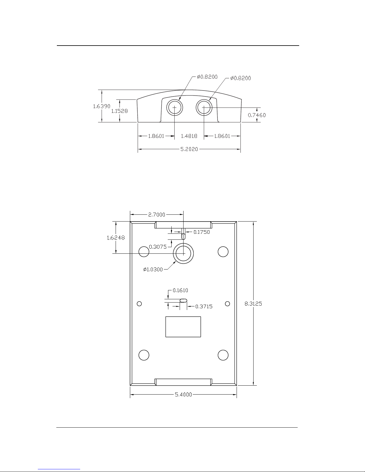
201T housing with bottom view and knock-out dimensions (in inches).
Note: A separate knock-out and conduit must be used when cables
connected to relay use more than 24 Vdc
201T housing and mounting dimensions
14 201T User Manual 511391
Honeywell 2/07
Page 17
Duct-type Installation
Duct-type Installation
The 201T can be duct-mounted. It is most efficient when air speed is
between 500 and 4,000 ft/minute (2.5 to 20.3 m/sec), and can be
installed either for fresh air or exhaust monitoring. Make sure to verify
all the requirements and existing regulations that may affect the choice
of its location. We recommend installation on a straight duct 3 feet (1 m)
away from any curve.
1. Post the drilling guide
to the ventilation duct.
2. Drill the openings for
the sampling tubes.
3. Insert the sampling
tube with lateral air
holes in the
appropriate connector,
orienting the air holes
facing airflow. Tighten
with the (8-32
screw on the
connector.
4. Insert the exhaust tube
into the appropriate
connector, orienting
the slant away from airflow. Tighten with the (8-32
the connector.
5. For a ventilation duct longer than 20 inches (51 cm), extra tubing is
necessary. It is preferable to drill a hole at the opposite side facing
the detection unit to support the far end of the tube. Seal the end of
the tube with the cork supplied. If necessary, seal the openings on
the duct around the tubings.
5/16”)
5/16”) screw on
511391 201T User Manual 15
2/07 Honeywell
Page 18

Duct-type Installation
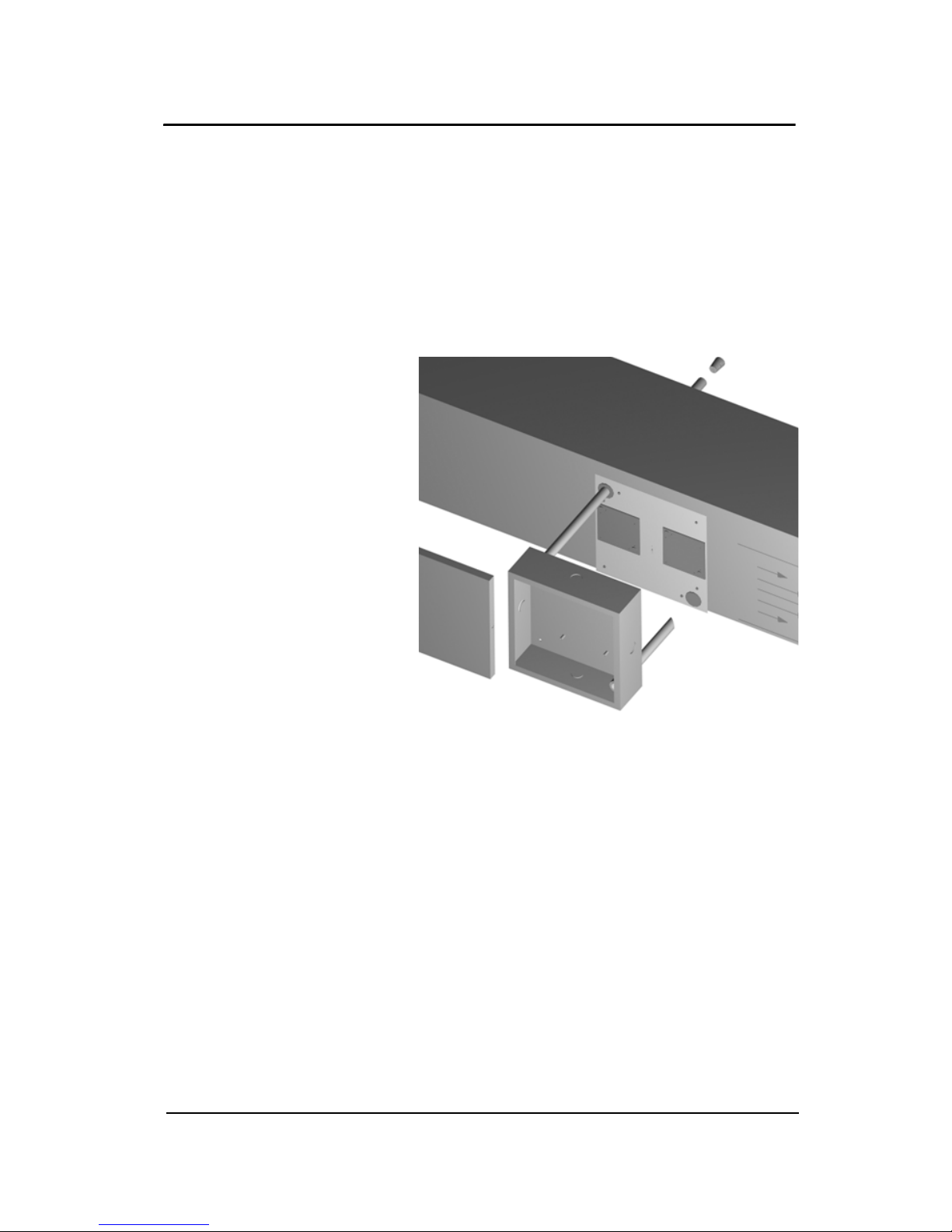
6. Install the box on the duct.
7. Connect the power and the outputs as shown in the ELECTRICAL
WIRING section.
8. Before mounting the cover of the sampling unit box, start the
ventilation feeding fan and check if there is any leakage. If
necessary, seal with air plugs.
9. The cover should be mounted using metallic screws (6-32
1/2”).
Note: To convert from CFM to velocity (ft./min.), divide the flow by the
area. Example: In a 2 ft. x 4 f t. duct, where the area is 8 sq. f t. and
the air velocity is 30,000 CFM : 30,000 CFM / 8 sq. ft. = 3,750 ft/
minute.
16 201T User Manual 511391
Honeywell 2/07
Page 19

Detection Range and Alarm Levels
Detection Range and Alarm Levels
Gas Detected Range Alarm A Alarm B AlarmC
C
O
2H4
CL
2
CO50 Carbon monoxide 0-51 ppm 9 ppm 15 ppm 45 ppm
CO100 Carbon monoxide 0-102 ppm 25 ppm 45 ppm 90 ppm
CO250 Carbon monoxide 0-255 ppm 25 ppm 200 ppm 225 ppm
CO500 Carbon monoxide 0-510 ppm 50 ppm 250 ppm 450 ppm
CO1000 Carbon monoxide 0-1020 ppm 100 ppm 500 ppm 900 ppm
S
H
2
H
2
HCL Hydrogen chloride 0-51 ppm 3 ppm 4 ppm 45 ppm
HCN Hydrogen cyanide 0-51 ppm 5 ppm 9 ppm 45 ppm
Ethylene oxide 0-20.4 ppm 1.0 ppm 5.0 ppm 9.0 ppm
Chlorine 0-15.3 ppm 0.5 ppm 1.0 ppm 13.0 ppm
Hydrogen sulfide 0-51 ppm 10 ppm 15 ppm 45 ppm
Hydrogen 0-2.55% Vol. 1.00% Vol. 2.00% Vol. 2.25% Vol.
NO Nitrogen monoxide 0-102 ppm 25 ppm 35 ppm 90 ppm
NO2
Nitrogen dioxide 0-10.2 ppm 0.72 ppm 2 ppm 9 ppm
O2 Oxygen 0-25.5% Vol. 19.5% Vol. 22.0% Vol. 23.0% Vol.
SO
2
Sulfur dioxide 0-10.2 ppm 2 ppm 5 ppm 9 ppm
R-11
R-12
Refrigerant Q2 0-1020 ppm 500 ppm 750 ppm 900 ppm
R-22
R134A
COMB Combustibles 0-102% LEL 25% LEL 50% LEL 90% LEL
A different alarm level may have been programmed in order to satisfy
the constraint of a particular application.
511391 201T User Manual 17
2/07 Honeywell
Page 20
Electrical Wiring
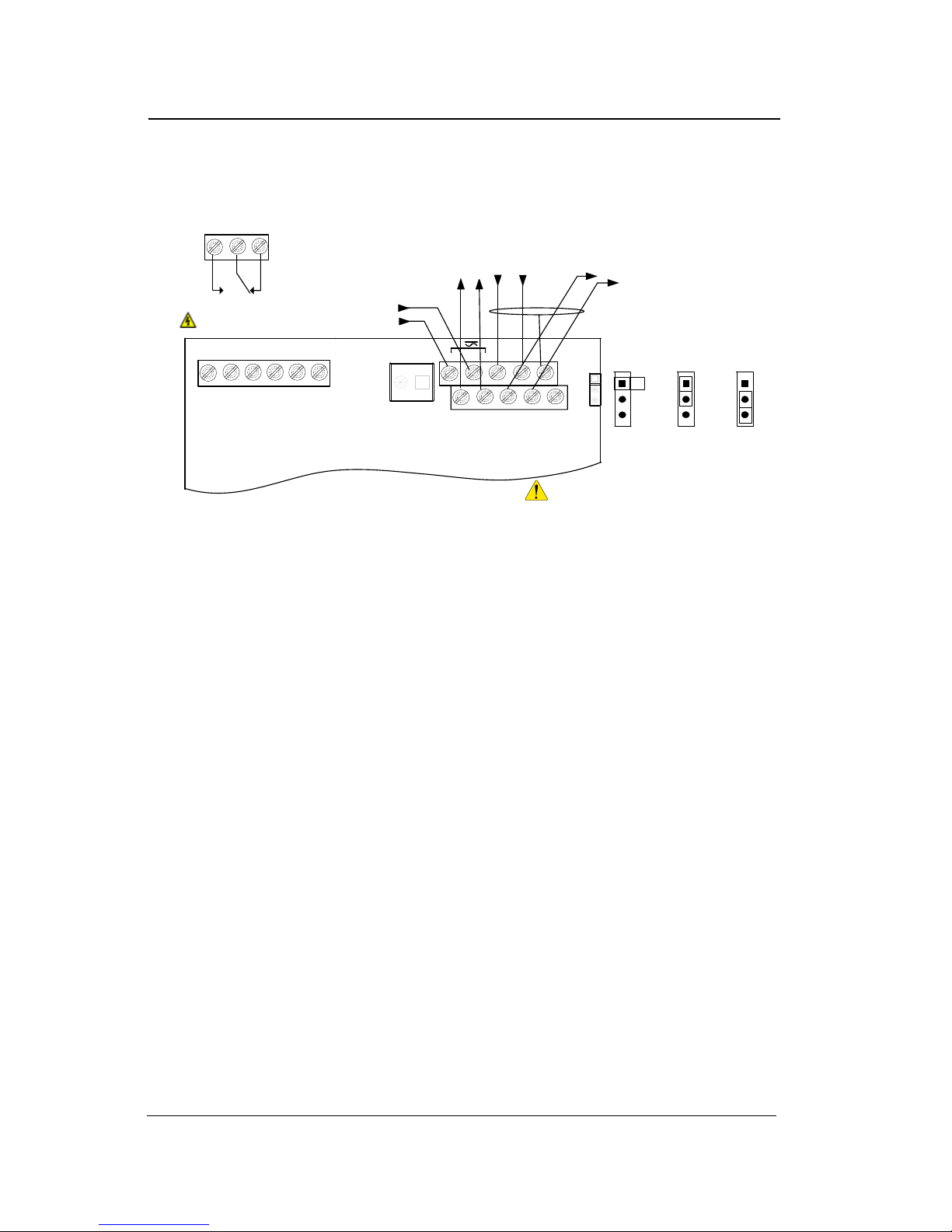
Electrical Wiring
RELAY OUTPUTS
N.O.
Normally open
N.C.
COMM
Normally closed
RISK OF ELECT R IC SHOCK
NO
NO
NC
V-
previous
V+
NC
J1
LD10
SORTIE 4@20mA OUTPUT
next
V+
-
V
previous
B
A
24V IN
+-
-
+
V
B
A
V
Shield
A
E.O.L.
next
B
EOL Positions
R>
J3
PT1
RC>
S2
Disabled
Always respect minimum
voltage requirements at
device
R
RC
18 201T User Manual 511391
Honeywell 2/07
Page 21

Remote Sensor Configuration (Optional)
Remote Sensor Configuration (Optional)
Master Board
When connecting to a remote sensor, use an 18 AWG cable gauge,
with a maximum length of 100 feet (30 m).
511391 201T User Manual 19
2/07 Honeywell
Page 22

Specifications
Specifications
Power Requirements: 17 - 27 Vac, 24 - 38 Vdc, 250 mA
Operating Temperature
Range:
Operating Humidity
Range:
Outputs: DPDT optional relay
Audible Alarm: 65 dBa - 1 m (option)
Dimensions: 8.4 in(H) x 5.3 in( W ) x 2.25 in(D)
Certifications
Q1 and Q2 CO : -4°F to 122°F (-20°C to 50°C)
Q2 : 32°F to 100°F (0 °C to 40 °C)
15 to 90% RH, (non-condensing)
5A, 30 Vdc or 250 Vac (resistive load)
4-20 mA (optional)
(21.3 cm x 13.4 cm x 5.7 cm )
CAN/CSA C22.2
ANSI/UL 61010-1
Periodic Inspections and Calibration
This unit requires calibration. The calibration frequency will be a
function of the operating conditions, including operating under extreme
temperatures, exposure to contaminants or gas concentrations greater
than the lower explosive limits. A calibration inspection must be
included as part of a routine maintenance to ensure proper operation of
the gas detection unit.
If unit span or zero cannot be adjusted, the sensor may be approaching
its end-of-life or has been contaminated and must be replaced.
20 201T User Manual 511391
Honeywell 2/07
Page 23

USER INTERFACE
The 10 red LEDs
indicate the gas
concentration
detected. Each red
LED represents 10%
of the reading scale.
For example, an
oxygen depletion
transmitter with a 21%
reading will have 8 red
LEDs lit.
If the FAULT (yellow)
DEL turns on, please
contact Honeywell
technical support for
assistance.
USER INTERFACE
Testing Procedure
When Powering ON,
the green LED lights
to indicate power ON.
DISPLAY (optional) .
An LCD display is available (as an option) in order to visualize the gas
concentration directly on the monitor.
Testing Procedure
Flow a Span gas at the recommended rate and observe the action of
the LEDs and analog outputs. Span gas can be purchased through your
local representative.
511391 201T User Manual 21
2/07 Honeywell
Page 24

USER INTERFACE
Testing Procedure
4-20 mA CONFIGURATION
4-20 mA CURRENT SOURCING OUTPUT CONFIGURATION
The transmitter supplies the loop current. The maximum impedance
supported by the loop is 400 ohms. Set jumpers on S3 at 1-2, 3-4 and
5-6 (pin 1 being next to S3).
WARNING
22 201T User Manual 511391
A dedicated power supply must be used with each unit.
Considerable damage may occur if this condition is not strictly
followed.
Honeywell 2/07
Page 25

USER INTERFACE
Testing Procedure
4-20 mA OUTPUT LOOP-POWERED OPERATION (Factory Setting)
The 4-20 mA output is factory set for loop-powered operation and
requires a power source of 12 Vdc to 30 Vdc. The overall impedance
depends on the voltage supplied at the 4-20 mA loop. Set jumpers on
S3 at 2-3, 4-5 and 6-7 for this type of configuration (pin 1 being next to
S3).
Permitted impedance in the 4@20 mA loop
Voltage Source Applied Total Impedance
12 Vdc 400 Ohms
16 Vdc 600 Ohms
20 Vdc 800 Ohms
24 Vdc 1 000 Ohms
30 Vdc 1 300 Ohms
3-wire configuration
511391 201T User Manual 23
2/07 Honeywell
Page 26

USER INTERFACE
Testing Procedure
4-wire configuration
24 201T User Manual 511391
Honeywell 2/07
Page 27

USER INTERFACE
Address Configuration
Address Configuration
In network mode, the multiple addresses are obtained by varying the
position of the dip switches and various jumpers. Figure below
illustrates the position of these various elements on the PCB. Based on
their configuration, the address will be modified.
The Binary addresses table gives the network addresses with their
corresponding binary addresses. The binary address must be transfer
in the Network vs Binary addresses table where the position of the
different PCB elements will be automatically obtained. The Jumpers
Positions figure illustrates the possible jumpers positions.
MIN, MAX
Jumper positions
12
ROCKER DOWN
3
4
ON
OFF
SW5, SW2
jumper positions
SW5
201T PCB: jumpers only
SW2
ON
OFF
Note: If the transmitter is equipped with a display, all values must be
reset to zero. The configuration of the addresses will then be
carried out using the display and keyboard.
511391 201T User Manual 25
2/07 Honeywell
Page 28

USER INTERFACE
Address Configuration
Network vs Binary Addresses
Network
address
1 0000 0000 49 0011 0000
2 0000 0001 50 0011 0001
3 0000 0010 51 0011 0010
4 0000 0011 52 0011 0011
5 0000 0100 53 0011 0100
6 0000 0101 54 0011 0101
7 0000 0110 55 0011 0110
8 0000 0111 56 0011 0111
9 0000 1000 57 0011 1000
10 0000 1001 58 0011 1001
11 0000 1010 59 0011 1010
12 0000 1011 60 0011 1011
13 0000 1100 61 0011 1100
14 0000 1101 62 0011 1101
15 0000 1110 63 0011 1110
16 0000 1111 64 0011 1111
17 0001 0000 65 0100 0000
18 0001 0001 66 0100 0001
19 0001 0010 67 0100 0010
20 0001 0011 68 0100 0011
21 0001 0100 69 0100 0100
22 0001 0101 70 0100 0101
23 0001 0110 71 0100 0110
24 0001 0111 72 0100 0111
25 0001 1000 73 0100 1000
26 0001 1001 74 0100 1001
27 0001 1010 75 0100 1010
28 0001 1011 76 0100 1011
29 0001 1100 77 0100 1100
30 0001 1101 78 0100 1101
31 0001 1110 79 0100 1110
32 0001 1111 80 0100 1111
33 0010 0000 81 0101 0000
34 0010 0001 82 0101 0001
35 0010 0010 83 0101 0010
36 0010 0011 84 0101 0011
37 0010 0100 85 0101 0100
38 0010 0101 86 0101 0101
Binary address
Network
address
Binary address
26 201T User Manual 511391
Honeywell 2/07
Page 29

USER INTERFACE
Address Configuration
Network
address
39 0010 0110 87 0101 0110
40 0010 0111 88 0101 0111
41 0010 1000 89 0101 1000
42 0010 1001 90 0101 1001
43 0010 1010 91 0101 1010
44 0010 1011 92 0101 1011
45 0010 1100 93 0101 1100
46 0010 1101 94 0101 1101
47 0010 1110 95 0101 1110
48 0010 1111 96 0101 1111
Binary address
Network
address
Binary address
Binary Address
Elements SW2 SW5 MAX MIN Dip4 Dip3 Dip2 Dip1
Binary address
Example= address 4300101010
Caption 0=INACTIVE 1=ACTIVE
511391 201T User Manual 27
2/07 Honeywell
Page 30

Page 31

Limited Warranty
Limited Warranty
Honeywell Analytics, Inc. warrants to the original purchaser and/or
ultimate customer ("Purchaser") of Vulcain products ("Product") that if
any part thereof proves to be defective in material or workmanship
within twelve (12) months, such defective part will be repaired or
replaced, free of charge, at Honeywell Analytics' discretion if shipped
prepaid to Honeywell Analytics at 4005 Matte Blvd., Unit G, Brossard,
Quebec, J4Y 2P4, in a package equal to or in the original container.
The Product will be returned freight prepaid and repaired or replaced if
it is determined by Honeywell Analytics that the part failed due to
defective materials or workmanship. The repair or replacement of any
such defective part shall be Honeywell Analytics' sole and exclusive
responsibility and liability under this limited warranty.
ReStocking Policy
The following restocking fees will apply when customers return products
for credit:
• 15% restocking fee will be applied if the product is returned within 1
month following the shipping date
• 30% restocking fee will be applied if the product is returned within 3
months following the shipping date
A full credit (less restocking fee) will only be issued if the product is in
perfect working condition. If repairs are required on the returned
product, the cost of these repairs will be deducted from the credit to be
issued.
No credits will be issued beyond the three month period.
511391 201T User Manual 29
2/07 Honeywell
Page 32

Limited Warranty
Exclusions
A. If Gas sensors are part of the Product, the gas sensor is
covered by a twelve (12) month limited warranty of the manufacturer.
B. If gas sensors are covered by this limited warranty, the gas
sensor is subject to inspection by Honeywell Analytics for extended
exposure to excessive gas concentrations if a claim by the Purchaser is
made under this limited warranty. Should such inspection indicate that
the gas sensor has been expended rather than failed prematurely, this
limited warranty shall not apply to the Product.
C. This limited warranty does not cover consumable items, such
as batteries, or items subject to wear or periodic replacement, including
lamps, fuses, valves, vanes, sensor elements, cartridges, or filter
elements.
Warranty Limitation and Exclusion
Honeywell Analytics will have no further obligation under this limited
warranty. All warranty obligations of Honeywell Analytics are
extinguishable if the Product has been subject to abuse, misuse,
negligence, or accident or if the Purchaser fails to perform any of the
duties set forth in this limited warranty or if the Product has not been
operated in accordance with instructions, or if the Product
serial number has been removed or altered.
511391 201T User Manual 30
2/07 Honeywell
Page 33

Limited Warranty
Disclaimer of Unstated Warranties
The warranty printed above is the only warranty applicable to this
purchase. All other warranties, express or implied, including, but not
limited to, the implied warranties of merchantability or fitness for a
particular purpose are hereby disclaimed.
Limitation of Liability
It is understood and agreed that Honeywell Analytics’ liability, whether
in contract, in tort, under any warranty, in negligence or otherwise shall
not exceed the amount of the purchase price paid by the purchaser for
the product and under no circumstances shall Honeywell Analytics be
liable for special, indirect, or consequential damages. The price stated
for the product is a consideration limiting Honeywell Analytics' liability.
No action, regardless of form, arising out of the transactions under this
warranty may be brought by the purchaser more than one year after the
cause of actions has occurred.
511391 201T User Manual 31
2/07 Honeywell
Page 34

Page 35

Dispositif de détection de gaz
201T
Manuel de l’utilisateur
ERP 511391
2/07
Page 36

Page 37

Avis et marques de commerce
Tous droits réservés par Honeywell International Inc.
Parution 511391 février 2007
Quoique cette information est présentée en bonne foi et est présumée exacte,
Honeywell décline la garantie tacite de la qualité marchande pour un emploi
particulier et offre aucune garantie exprès, à l’exception des conventions écrites
avec et pour ses clients.
Honeywell ne sera, sous aucune circonstance, responsable à qui que ce soit
pour des dommages spéciaux ou indirectes. Les informations et les
spécifications dans ce document sont susceptibles d’être modifiées sans
préavis.
511391 Manuel de l’utilisateur 201T iii
2/07 Honeywell
Honeywell Analytics
4005 Matte Blvd, Local G
Brossard, Québec, J4Y 2P4
Page 38

Page 39

Coordonnées
Web
Les sites Web suivant d’Honeywell peuvent être utiles pour nos clients :
Organisation Honeywell Adresses WWW (URL)
Honeywell Analytics http://honeywellanayltics.com
Corporate http://www.honeywell.com
International http://content.honeywell.com/global/
Téléphone
Utiliser les numéros de téléphone ci-dessous pour nous contacter :
Organisation Numéro de téléphone
États Unis
et Canada
Asie Pacifique
Europe
Amérique latine
Honeywell Analytics
Honeywell Asia Pacific Inc.
Hong Kong
Honeywell Pace
Brussels, Belgium
Honeywell International Inc.
Sunrise, Floride, É.U.
1-800-563-2967
1-450-619-2450
Fax: 1-888-967-9938
(852) 23 31 9133
[32-2]728-2711
(954) 845-2600
Informations des ventes
Nous contacter à sales@vulcaininc.com
511391 Manuel de l’utilisateur 201T v
2/07 Honeywell
Page 40

Page 41

Définitions des symboles
Le tableau suivant contient la liste des symboles utilisés dans ce
document pour indiquer certaine conditions :
Symbole Définition
ATTENTION: Identifie une information demandant
une attention spéciale
Truc: Identifie un conseil ou un truc pour
l’utilisateur, souvent concernant une tâche
RÉFÉRENCE- INTERNE Indique une source
d’information supplémentaire à l’intérieur du
document.
Indique une situation à éviter pouvant entraîner des
ATTENTION
dommages au système ou la perte de travail
(documents) ou pouvant prévenir l’opération
normale du système.
ATTENTION : Indique une situation potentiellement
dangereuse qui peut entraîner des blessures
mineures ou modérées si pas évité. Peut
également signaler des actions dangereuses
ATTENTION: Un symbole sur l’équipement qui
réfère l’utilisateur à la documentation pour de plus
amples informations. Ce symbole apparaît à côté
des informations nécessaires dans le manuel.
AVERTISSEMENT: Indique une situation
potentiellement dangereuse qui peut entraîner des
blessures majeures ou la mort si pas évité.
AVERTISSEMENT Un symbole sur l’équipement
qui réfère l’utilisateur à la documentation pour de
plus amples informations. Ce symbole apparaît à
côté des informations nécessaires dans le manuel.
511391 Manuel de l’utilisateur 201T vii
2/07 Honeywell
Page 42

Page 43

Table des matières
Déballage .......................................................................................... 11
Description ........................................................................................ 11
Notes importantes ............................................................................. 11
Déterminer le nombre de moniteurs .................................................. 12
Installation murale ............................................................................. 13
Installation montage de gaine ........................................................... 15
Plage de détection et niveaux d’alarme ............................................ 17
Détails de connexion ......................................................................... 18
Connexion de sonde à distance ............................................................ 19
Spécifications ................................................................................... 20
Inspection périodique et étalonnage ................................................. 20
INTERFACE USAGER ...................................................21
Procédure de test .............................................................................. 21
Configurations 4-20 mA ..................................................................... 22
Configuration active ............................................................................... 22
Configuration passive ........................................................................... 23
Configuration des adresses ............................................................... 25
GARANTIE LIMITÉE ......................................................29
Garantie limitée ..................................................................................... 29
Politique de Retour ................................................................................ 29
Exclusions ............................................................................................. 30
Limitation et exclusion de la garantie .................................................... 30
Dénégation de responsabilité d’autres garanties .................................. 31
Limitation de responsabilité ................................................................... 31
511391 Manuel de l’utilisateur 201T ix
2/07 Honeywell
Page 44

Page 45

Déballage
Déballage
Dés son ouverture, vérifier le contenu de l’emballage. Assurez-vous
que vous avez reçu tous les éléments tels qu’indiqués sur le bon de
connaissement.
Description
Les transmetteurs de la série 201T offrent la détection d’un large
éventail de gaz toxiques et explosifs. Les transmetteurs fonctionnent
soit en mode autonome ou en mode réseau via leurs sorties
optionnelles 4-20 mA ou leurs relais.
Des capteurs catalytiques sont utilisés pour détecter des centaines de
différents gaz et concentrations de vapeurs inflammables. Les gaz
toxiques sont détectés par les cellules électrochimiques, tandis que des
cellules à pile métal-air sont utilisées pour la détection de l'oxygène. Par
ailleurs, une deuxième génération de détecteurs semiconducteurs
fournit une solution très efficace pour une variété d’applications.
Notes importantes
Ces directives doivent être strictement respectées pour assurer le
bon fonctionnement de l’équipement. Si elles ne sont pas suivies,
Honeywell ne se tiendra aucunement responsable des incidents
pouvant en découller :
• Localiser chaque unité à un endroit facile d’accès pour un
technicien.
• Éviter toute localisation des unités près des sources de vibrations.
• Évitez d’installer les unités près d’équipements émettant des
interférences électromagnétiques.
• Évitez les emplacements o la température change rapidement.
• Avant de débuter l’installation, vérifiez tous les codes, normes ou
législations pouvant affecter le choix de l’emplacement.
511391 Manuel de l’utilisateur 201T 11
2/07 Honeywell
Page 46

Déterminer le nombre de moniteurs
Déterminer le nombre de moniteurs
Le rayon de surveillance de chaque type de moniteur détermine la
superficie couverte.
Gaz détecté
CO Monoxyde de carbone 15 m (50 pi) 707 m ca. (7 854 pi ca)
NO
Autres 7 m (23 pi) 154 m ca. (1 257 pi ca)
Dioxide d’azote 15 m (50 pi) 707 m ca. (7 854 pi ca)
2
Rayon de
surveillance
Zone couverte
Plusieurs facteurs peuvent influencer le nombre de transmetteurs
nécessaires, soit : l’application visée, le type de gaz et le niveau de
protection désiré. Évidemment, un plus grand nombre de détecteurs
offrira une meilleure protection et sécurité.
12 Manuel de l’utilisateur 201T 511391
Honeywell 2/07
Page 47

Installation murale
Installation murale
L’installation de l’unité nécessite la fixation du boîtier à l’endroit prévu.
Faites ensuite les différentes connections d’après la configuration
désirées.
Densité
Gaz détecté
O
C
2H4
CL
CO
H
2
H2S
2
Oxyde d’éthylène 1.50 30 cm (1 pi) du sol
Chlore 2.50 30 cm (1 pi) du sol
Monoxyde de
carbone
Hydrogène 0.07 30 cm (1 pi) du plafond
Sulfure d’hydrogène 1.19 30 cm (1 pi) du sol
HCL Chlorure d’hydrogène 1.30 30 cm (1 pi) du sol
NO Monoxyde d’azote 1.04 30 cm (1 pi) du sol
NO
O
2
SO
2
2
Dioxyde d’azote
Oxygène 1.43 1-1.5 m (3-5 pi) du sol
Dioxyde de soufre 2.25 30 cm (1 pi) du sol
R11
R12
Frigorigènes 30 cm (1 pi) du sol
R22
R134A
La plupart des explosifs sont plus lourds que l’air, excepté le
méthane, l’hydrogène, l’éthylène et l’acétylène. Pour les gaz plus
Expl
lourd que l’air, les détecteurs devraient êtres installés à 30 cm du
sol. Pour les combustibles plus légers que l’air, les détecteurs
devraient êtres installés à 30 cm du plafond, près de la source
potentielle de fuite.
relative
Hauteur d’installation
(air=1)
0.968 1-1.5 m (3-5 pi) du sol
1.58
(froid)*
30 -100 cm (1-3 pi) du
plafond
* Peut différer pour certaines applications. Du NO2 chaud à la sortie d’un système
d’échappement, est plus léger que 1,58.
Note: Les hauteurs d'installation de détecteurs recommandées par
Vulcain représentent des directives générales. Toujours vérifier
les normes et les lois locales avant de procéder à l'installation.
Celles-ci ont préséance sur les recommandations du fabricant.
511391 Manuel de l’utilisateur 201T 13
2/07 Honeywell
Page 48

Installation murale
Boîtier 201T, vue en sous-face, avec dimensions du boîtier et des
poinçons (en pouces).
Note: Utiliser un poinçon et un conduit séparé si le fils allant au relais
utilise plus de 24 Vac.
Dimensions de boîtier 201T, avec dimensions et mesures de montage.
14 Manuel de l’utilisateur 201T 511391
Honeywell 2/07
Page 49

Installation montage de gaine
Installation montage de gaine
Ce système est utilisé pour analyser les concentrations de gaz dans les
gaines de ventilation. Efficace lorsque la vélocité d’air varie entre 2,5 et
20,3 mètres par seconde, il est généralement installé sur la gaine de
retour principale avant les ventilateurs de recirculation. Vous devez
vérifier l’ensemble des codes ou législations pouvant affecter les
travaux. L’installation est recommandée sur une conduite droite à plus
de 1 mètre de toute déviation.
1. Coller ou fixer le
guide de perçage
sur la gaine de
ventilation.
2. Percer les trous
pour les tubes
d’échantillonnage
d’un diamètre de
2,5 cm.
3. Installer le tube
d’échantillonnage
perforé dans
l’ancrage d’entrée
d’air en plaçant les
trous face au débit
d’air. Fixer le tube
sur l’ancrage avec la vis. Boucher l’extrémité du tube d’admission
d’air avec un bouchon de liège.
4. Installer le tube d’échantillonnage bisauté dans l’ancrage de sortie
d’air en plaçant l’ouverture à angle ouvert dans le sens du débit
d’air, soit opposé aux orifices de l’autre tube. Fixer le tube sur
l’ancrage avec la vis (8-32 5/16”).
5. Pour une gaine de plus de 53 cm, utiliser les rallonges de tubes.
Pour un meilleur soutien, il est préférable que le tube perforé
traverse totalement la gaine. Àcet effet, un trou doit être percé sur
la face opposée de la gaine afin de supporter l’extrémité du tube.
Au besoin, calfeutrer les trous excédants sur la gaine. Boucher
l’extrémité du tube d’admission d’air avec un bouchon de liège.
6. Installer l’unité sur la conduite.
511391 Manuel de l’utilisateur 201T 15
2/07 Honeywell
Page 50

Installation montage de gaine
7. Brancher l’alimentation et les sorties tel qu’indiqué dans la section
RACCORDEMENTS ÉLECTRIQUES.
8. Avant de fermer le couvercle, démarrer la ventilation et vérifier qu’il
n’y a pas de fuites d’air. Calfeutrer au besoin.
9. Le couvercle doit être vissé avec des vis métalliques (6-32 1/2”).
Note: Pour convertir le débit d’une gaine de ventilation, soit une valeur
en LPS (litre par seconde) en vélocité; il faut diviser le débit p ar 1
000 puis par la surface de la gaine. Exemple : une gaine de 0,5
mètre de hauteur par 1 mètre de pr ofondeur avec un débit de
30 000 LPS donne une vélocité de 60 mètres par seconde.
30 000 l/s = 30 000/(1000*0,5*1) = 60 m/s
16 Manuel de l’utilisateur 201T 511391
Honeywell 2/07
Page 51

Plage de détection et niveaux d’alarme
Plage de détection et niveaux d’alarme
Gaz détecté Plage
CO50
CO
100
CO250
CO500
CO1000
NO Monoxyde d’azote 0-102 ppm 25 ppm 35 ppm 90 ppm
NO
2
H
2
CL
2
SO
2
H
S
2
HCL Chlorure d’hydrogène 0-51 ppm 3 ppm 4 ppm 45 ppm
HCN Cyanure d’hydrogène 0-51 ppm 3 ppm 9 ppm 45 ppm
C
O
2H4
O
2
R11
R12
R22
R134A
Expl Explosifs 0-102% LIE 25% LIE 50% LIE 90% LIE
Monoxyde de carbone
Dioxyde d’azote 0-10.2 0.72 ppm 2 ppm 9 ppm
Hydrogène 0-2.55% vol 1.0% vol 2.0% vol 2.25% vol
Chlore 0-15.3 ppm 0.5 ppm 1.0 ppm 13.0 ppm
Dioxyde de soufre 0-10.2 ppm 2 ppm 5 ppm 9 ppm
Sulfure d’hydrogène 0-51 ppm 10 ppm 15 ppm 45 ppm
Oxyde d’éthylène 0-20.4 ppm 1.0 ppm 5.0 ppm 9.0 ppm
Oxygène 0-25.5% vol 19.5% vol 22.0% vol 23.0% vol
Frigorigène Q2 1-1020 ppm 500 ppm 750 ppm 900 ppm
0-51 ppm 9 ppm 15 ppm 45 ppm
0-102 ppm 25 ppm 45 ppm 90 ppm
0-255 ppm 25 ppm 200 ppm 225 ppm
0-510 ppm 50 ppm 250 ppm 450 ppm
0-1020 ppm 100 ppm 500 ppm 900 ppm
Alarme AAlarme BAlarme
C
Un seuil d'alerte différent a pu être programmé afin de satisfaire la
contrainte d'une application particulière.
511391 Manuel de l’utilisateur 201T 17
2/07 Honeywell
Page 52

Détails de connexion
Dét ails de connexion
SORTIES RELAIS
N.O. N.C.
Normalement ouvert
RISQUE DE CHOC ÉLECTRIQUE
NC
COMM
Normalement fermé
NO
NO
précédent
V-
V+
NC
J1
LD10
SORTIE 4@20mA OUTPUT
+-
PT1
suivant
V+
-
V
24V IN
-
+
V
V
J3
Toujours respecter les exigences
minimales d’alimentation à l’appareil
précédent
B
A
B
A
Shield
A
E.O.L.
suivant
B
Positions cavalier fin de ligne
R>
RC>
S2
Désactivé
R
RC
18 Manuel de l’utilisateur 201T 511391
Honeywell 2/07
Page 53

Détails de connexion
Connexion de sonde à distance
(facultatif)
Lors de la connexion d’une sonde à distance au 201T, il est nécessaire
d’utiliser un câble de type 18 AWG, sur une longueur maximale de 100
pieds (30 mètres).
511391 Manuel de l’utilisateur 201T 19
2/07 Honeywell
Page 54

Spécifications
Spécifications
Alimentation requise : 17 à 27 Vca, 24 à 38 Vcc, 250 mA
Plage de température :
Plage d’humidité : 15 à 90% HR non-condensé
Nombre de sorties :
Alarme sonore : 65 dBA à 1 mètre en option
Dimensions : 21,3 cm (H) x 13,4 cm (L) x 7,5 cm (P)
Homologations
Q1 and Q2 CO : -4 ×F to 122 ×F / -20 ×C to 50
×C Q2 : 32×F to 100×F / 0 ×C to 40 ×C
1 relais DPDT en option 5 A, 30 Vcc ou 250 Vca
(charge résistive) 4-20 mA en option
CAN/CSA C22.2
ANSI/UL 61010-1
Inspection périodique et étalonnage
Cet appareil doit être étalonné. La fréquence d’étalonnage sera dictée
par les conditions spécifiques d’utilisation comme l’exposition à des
températures extrêmes, à des contaminants ou à des concentrations.
L’étalonnage doit être inclus dans un programme de prévention visant à
assurer le fonctionnement de l’unité de détection.
Lorsque l’étalonnage ne peut s’effectuer correctement, la cellule doit
être remplacée.
20 Manuel de l’utilisateur 201T 511391
Honeywell 2/07
Page 55

INTERFACE USAGER
Procédure de test
INTERFACE USAGER
Les dix premiers DEL
rouges indiquent la
concentration de gaz
détecté. Chaque DEL
rouge représentent 10%
de la plage de lecture.
Par exemple, un
transmetteur d’oxygène
ayant une lecture de
21% aurait 2 DEL rouges
allumées.
La DEL jaune, au dessus
de la DEL verte, indique
une panne du système.
En cas de panne,
contacter Honeywell afin
d’obtenir de l’assistance.
La DEL verte est
allumée à la mise sous
tension et indique le
fonctionnement de
l’unité.
Un afficheur ACL est disponible (en option) afin de visualiser la
concentration de gaz directement sur le moniteur.
Procédure de test
Faites circuler un gaz d'étalonnage au débit recommandé et observez
l'action des DEL et des sorties analogiques. Vous pouvez contacter
notre département technique pour obtenir un tel service.
511391 Manuel de l’utilisateur 201T 21
2/07 Honeywell
Page 56

INTERFACE USAGER
Configurations 4-20 mA
Configurations 4-20 mA
Configuration active
Le transmetteur fournit la tension à la boucle de courant. L’impédance
maximale que peut supporter la boucle est de 400 Ohms. Pour
configurer ce mode, il faut placer les trois cavaliers de S3 dans la
position 1-2, 3-4 et 5-6 (Position 1 étant adjacente à S3).
ATTENTION
24 VCA
24 VCA
LÉGENDE
TRANSMETTEUR 1
24 VCA
Connection à un transmetteur
Connection à plusieurs transmetteurs
4-20 mA
TRANSMETTEUR X...
24 VCA
SYSTÈME DDC
4-20 mA
Une alimentation séparée pour chacune des unités est
requise pour cette configuration. D’importants dommages
peuvent survenir si les conditions ci-haut mentionnées ne
sont pas correctement suivies.
22 Manuel de l’utilisateur 201T 511391
Honeywell 2/07
Page 57

INTERFACE USAGER
Configurations 4-20 mA
Configuration passive
(Configuration réglée en usine)
La sortie 4-20 mA passive nécessite une alimentation de 12 Vcc à 30
Vcc. L’impédance totale dépend du voltage de l’alimentation de la
boucle 4-20 mA. Pour configurer ce mode, il faut placer les trois
cavaliers de S3 dans la position 2-3, 4-5 et 6-7 (position 1 étant
adjacente à S3).
Impédance permise dans la boucle 4-20 mA
Tension d’alimentation de la bo ucle Impéd a nce totale
12 Vcc 400 Ohms
16 Vcc 600 Ohms
20 Vcc 800 Ohms
24 Vcc 1 000 Ohms
30 Vcc 1 300 Ohms
Configuration à 3 fils
TRANSMETTEUR 1
24 VCA
4-20 mA
24 VCC
TRANSMETTEUR X...
LÉGENDE
Connection à un transmetteur
Connection à plusieurs transmetteurs
SYSTÈME DDC
511391 Manuel de l’utilisateur 201T 23
2/07 Honeywell
Page 58

INTERFACE USAGER
Configurations 4-20 mA
Configuration à 4 fils
LÉGENDE
Connection à un transmetteur
Connection à plusieurs transmetteurs
TRANSMETTEUR 1
24 VCA
4-20 mA
24 VCC
TRANSMETTEUR X...
24 VCA
SYSTÈME DDC
4-20 mA
24 Manuel de l’utilisateur 201T 511391
Honeywell 2/07
Page 59

INTERFACE USAGER
Configuration des adresses
Configuration des adresses
En mode réseau, les multiples adresses s'obtiennent en variant la
position des commutateurs DIP et des différents cavaliers. L'image cidessous nous montre la position de ces différentes composantes sur le
PCB. D'après leur configuration, l'adresse sera modifiée.
Le tableau Adresses Reseaux vs Binaires fournit les adresses réseaux
correspondantes aux valeurs binaires. D'après l'adresse recherchée, la
valeur binaire doit être reportée dans le tableau Adresse Binaire; la
position des différentes composantes du PCB sera automatiquement
obtenue. L'image Positions des cavaliers illustre les positions possibles
des cavaliers.
Positions des cavaliers
MIN, MAX
12
ROCKER DOWN
3
4
ON
OFF
Note: Si le transmetteur est équipé d'un afficheur, toutes les valeurs
doivent être remises à zéro. La configuration de l’adresse se fera
alors à l'aide de l'afficheur et du clavier.
511391 Manuel de l’utilisateur 201T 25
2/07 Honeywell
SW5
Carte de circuit 201T PCB:
cavaliers seulement
SW2
Positions des cavaliers
SW5, SW2
ON
OFF
Page 60

INTERFACE USAGER
Configuration des adresses
Adresses Réseaux vs Binaires
Adresse
réseau
1 0000 0000 49 0011 0000
2 0000 0001 50 0011 0001
3 0000 0010 51 0011 0010
4 0000 0011 52 0011 0011
5 0000 0100 53 0011 0100
6 0000 0101 54 0011 0101
7 0000 0110 55 0011 0110
8 0000 0111 56 0011 0111
9 0000 1000 57 0011 1000
10 0000 1001 58 0011 1001
11 0000 1010 59 0011 1010
12 0000 1011 60 0011 1011
13 0000 1100 61 0011 1100
14 0000 1101 62 0011 1101
15 0000 1110 63 0011 1110
16 0000 1111 64 0011 1111
17 0001 0000 65 0100 0000
18 0001 0001 66 0100 0001
19 0001 0010 67 0100 0010
20 0001 0011 68 0100 0011
21 0001 0100 69 0100 0100
22 0001 0101 70 0100 0101
23 0001 0110 71 0100 0110
24 0001 0111 72 0100 0111
25 0001 1000 73 0100 1000
26 0001 1001 74 0100 1001
27 0001 1010 75 0100 1010
28 0001 1011 76 0100 1011
29 0001 1100 77 0100 1100
30 0001 1101 78 0100 1101
31 0001 1110 79 0100 1110
32 0001 1111 80 0100 1111
33 0010 0000 81 0101 0000
34 0010 0001 82 0101 0001
35 0010 0010 83 0101 0010
36 0010 0011 84 0101 0011
37 0010 0100 85 0101 0100
38 0010 0101 86 0101 0101
Adresse binaire
Adresse
réseau
Adresse binaire
26 Manuel de l’utilisateur 201T 511391
Honeywell 2/07
Page 61

INTERFACE USAGER
Configuration des adresses
Adresse
réseau
39 0010 0110 87 0101 0110
40 0010 0111 88 0101 0111
41 0010 1000 89 0101 1000
42 0010 1001 90 0101 1001
43 0010 1010 91 0101 1010
44 0010 1011 92 0101 1011
45 0010 1100 93 0101 1100
46 0010 1101 94 0101 1101
47 0010 1110 95 0101 1110
48 0010 1111 96 0101 1111
Adresse binaire
Adresse
réseau
Adresse binaire
Adresses Binaires
Composantes SW2 SW5 MAX MIN Dip4 Dip3 Dip2 Dip1
Adresse binaire
Exemple= adresse 4300101010
Légende 0=INACTIF 1=ACTIF
511391 Manuel de l’utilisateur 201T 27
2/07 Honeywell
Page 62

Page 63

Garantie limitée
Garantie limitée
Garantie limitée
Honeywell Analytics, Inc. garantie à l’Acheteur d’origine et/ou au client
final (« Acheteur ») de produits Vulcain (« Produit ») que si une pièce
quelconque du produit s’avère défectueuse , soit en matériel ou en
main d’oeuvre, dans douze (12) mois, cette pièce sera réparée ou
remplacer, sans frais, à la discrétion d’Honeywell Analytics si expédié,
port payé, à Honeywell Analytics at 4005 Matte Blvd., Unit G, Brossard,
Quebec, J4Y 2P4, dans l’emballage d’origine ou l’équivalent. Le Produit
sera retourné au client port payé si Honeywell Analytics détermine que
la pièce est défectueuse en raison de défaut matériel ou de main
d’oeuvre. La réparation ou le remplacement d’une telle pièce
défectueuse représente la seule et exclusive responsabilité
d’Honeywell Analytics sous cette garantie limitée.
Politique de Retour
Les frais suivants seront applicables lors de retour de produit pour
crédit :
• Des frais de retour de 15% seront appliqués lorsque le produit est
retourné dans le 1er mois suivant la date d’expédition
• Des frais de retour de 30% seront appliqués lorsque le produit est
retourné dans les 3 mois suivant la date d’expédition
Un crédit total (moins les frais de retour) sera uniquement appliqué si le
produit est en parfait état de fonctionnement. Si des réparations sont
nécessaires sur le produit retourné, les frais de cette réparation seront
déduit du crédit.
Auncuns crédits ne seront appliqués pour les retours après les 3 mois
suivant la date d’expédition.
511391 Manuel de l’utilisateur 201T 29
2/07 Honeywell
Page 64

Garantie limitée
Exclusions
A. Si des capteurs de gaz font partie du Produit, le capteur est
couvert par une garantie limitée de douze (12) mois du fabricant.
B. Si les capteurs de gaz sont couverts par cette garantie limitée,
le capteur sera assujeti à l’inspection par Honeywell Analytics pour
l’exposition prolongée à des concentrations de gaz élevées si
l’Acheteur fait une réclamation sous cette garantie limitée. SI
l’inspection indique que la cause de la défectuosité est l’épuisement du
capteur plutôt qu’un défaut, cette garantie ne s’appliquera pas au
Produit.
C. Cette garantie limitée ne s’applique pas au produits
consommables, tels les piles, ou les articles sujets à l’usure ou au
remplacement régulier, incluant les lampes, les fusibles, les valves, les
aubes, les élements de sonde, les cartouches ou les éléments de
filtres.
Limitation et exclusion de la garantie
Honeywell Analytics n’aura aucun autre responsabilité sous cette
garantie limitée. Toutes responsabilités de garantie d’Honeywell
Analytics sont annulées si le Produit a subi des abus, de la
négligeance, un accident ou si l’Acheteur est en défaut de ses
obligations tels que décrit dans cette garantie ou si le Produit n’a pas
été utilisé selon les instructions ou si le numéro de série du Produit été
enlevé ou modifié.
511391 Manuel de l’utilisateur 201T 30
2/07 Honeywell
Page 65

Garantie limitée
Dénégation de responsabilité d’autres garanties
La garantie ci-haut est la seule garantie applicable à cet achat. Toutes
autres garanties, soit implicites ou exprès, incluant mais pas limité à,
les garanties tacites de qualité marchande ou de l’aptitude à un emploi
particulier sont dénéguées par le présent document.
Limitation de responsabilité
Il est entendu que la responsabilité d’Honeywell Analytics, soit en
contrat, en délit civil, sous n’importe quelle garantie de responsabilité,
en négligence ou autrement n’excédera pas le prix d’achat payé par
l’Acheteur pour le produit. Honeywell Analytics ne sera pas
responsable, sous aucune circonstance, pour des dommages spéciaux
ou indirectes. Le prix déclaré pour le produit est une considération
limitant la responsabilité d’Honeywell Analytics. Aucune action, en
quelle forme que soit, survenant des transactions sous cette garantie
peuvent être entreprises par l’Acheteur plus d’un an après l’occurence
de la cause de ces actions.
511391 Manuel de l’utilisateur 201T 31
2/07 Honeywell
Page 66

 Loading...