

Honda P-50 Shop Manual
SHOP
MANUAL
HONDA
-.
MODEL
P50
•
I
-
I FOREWORD
The
P-50
is a gasoline engine powered bicy-
cle,
affording
all
the
simplicities
of
the
bicycle
with
the
powered
features
of a mopet, yet
so
easy
to
handle
that
anyone who
Is
able
to
ride a
bicycle can ride
the
P-50
without
any previous
- experience.
It
is designed
to
fulfill
the
need
for
a
safe, economical and easy
handling
family
trans-
portation.
This manual has been prepared
as
a servi-
cing guide
for
the
P-50
, and all personnel who
will
be
servicing
the
P-50
should read
thi
s manual
carefully
to
become
familiar
with
all
of
its
sections.
The
manual is
written
in
tow
parts, construct-
ion and maintenance inspection,
for
easy reference.
Any
revisions
to
this manual will
be
notified
by
the
Service Bulletin.
July
20
,
1967
Service
Department
Honda
Motor
Company
Ltd.
II
CONTENTS
II
1.
FEATURES
2.
SPECIFICATION
&
PERFORMANCE
SPECIFICATION
FOR P-50
. .. . . . . . .
..
. .. . .
..
. . . . . . . . . . . . . . . .. . .
.. . ..
. . . . . . . . . 2
DRIVING
PERFORMANCE
CURVES
..
. . .. .
..
. .
..
.. . .
.. .. .. ..
. .. . . .. . .. . . . . . . 4
ENGINE
PERFORMANCE
CURVES
....
.........................................
4
WIRING
DIAGRAM
. . . . . . . . . . . . . . . . . . . . . . . . . . . . . . . . . . . . . . . . . . . . . . . . . . . . . . . . . . . . . . . 6
(For
General
export
type
) . ..
..
..
.. . ..
. .
..
. . . . . . .
..
. . . . . . . .
.. . .. . ..
..
. . . .
.. . ..
. . . . . 6
(For
U.
S.
A.
export
type
) . . . . .
.. . .. . .. . ..
. . . . .
.. . ..
. .
.. .. .. .. . .. ..
. . . .
.. . ..
.. . .. 7
(For F
rance
and
Belgium
export
type
) ..
.. . .. . ..
. . . . .
..
. .
..
. .. ...
.. . .. . ..
..
.. ..
8
(F
or
Holland
export
type
) . . . . . . . . . . . .
..
. .
..
. . . .
..
. . . .
..
. . . . . . . . . . . . . . .
..
. . . .
..
. .
..
8
(F
or
England
export
type
) . . . . . . . . . . . . . . . . . . . . . . . . . . . . . . . . . . . . . . . . . . . . . . . . . . . . . . . . . 9
(For
Germany
export
type) ..
. .
.. .. . ..
. .
.. . ..
. . . . . . . . .
.. . .. . .. . .. . ..
. .
.. . ..
. . . . . . 9
DIMENSIONAL
DRAWING
....................................
.. ..
.......
.......
10
GENERAL
DESCRIPTION
3.
ENGINE
Operation
of
Four-cycle
Engin
e ....
......
....
.....
..............
....
........
12
Intake (Intake of the
fuel-air
mixture
) ..
.....
....
....
....
....
......
....
12
Air
Cleaner .....
...
.. ..
.....................
....
.....
.............
...
.......... ....
......
12
Fuel T
ank
................
...
......
.............................
... .. ..
.....
......
.........
13
Fuel Cock
............
... . .
.......................
..........
... .
...............
............
13
Carbureto
r ..
................
.. ... .
.............................
..
........
....
.........
.. 13
P-50
Carburetor
Construction
.........................................................
16
Operation
of P-50
Carburetor
Component
Parts
.................................
18
Compression (Compress
the
fuel
air
mixture
in
the
cylinder
) ... 19
Piston
...........
...........
.......................
......
.. ............
.......
......
......... 19
Piston
Offset
...............
.......................................
.......
. ........
.... 20
Piston
Shape ................
.. ......
.........
.............................................
20
Pist
on
Rings
..................
...............................
... .
.........................
20
Cylinder
.........
................................................................
.... ....
...
21
Combustion (Ignition
of
the compressed air-fuel
mixture
by
the
spark
plug
to
cause
combustion) .................
.................
.....
21
Ignition
System
...............
......
......................................................
21
Flywheel
AC
Generator
...
.......
.....................
.. .....
...
............
..........
22
Ignition Coil
...............................
..
.........
......
..............................
22
I
1
I
FEAT
~
~
Engine
1. CHAIN
DRIVEN
0.
H.
C.,
4·CYCLE
ENGINE
is used
to pro
vide quiet efficient power.
2.
POWER
TRA
NSMI
SSI
ON
IS
PERFORMED
by
a specially engineered
thr
ee
stage speed
n'!duction and a reliable centrifugal clutch
that
automatically disengages
at
idling speed
and engages when
throttle
is opened ; eliminating any
need for a manual clutch
or
gear
shift.
3.
ENGINE
START
ING
AND
STOPPING
is by opening or closing the decompression lever
which relieve the compression from the cylinder.
4 .
THE
ENGINE
AND
THE
COMPLETE
POWER
TRANSMI
SSION
UNIT
are contai
ned
within
th
e rear wheel hub together
with
the rear brakes.
5.
SH
IFTING THE
CYCLI
NG
LEVER
located
on
the engine disengages the engi
ne
to
permit
pedal operation
of
the P·
50.
6.
CHOKE
BUTTON
IS
CONVENIENTLY LOCA
TED
on the steering
head,
accessible while
riding.
Frame
1. A
STEP THROUGH
FRAME WITH A LOW
CENTER·OF
·GRAVITY makes
it
easy to mount
or dismount
and
provides
for
greater stability. Fra
me
main structure is a monocoque,
welded pressed steel sheet
for
high strength
and
ridgidity.
2.
EXPANDING
BRAKE
SHOES
in
the
front
and
clamping band brakes
in
the rear operated
independently by the handle levers assure good braking.
3.
AUTOMATIC
ARM
CHAIN
TENSIONER
constantly maintains the pedal drive cllain
in
proper
tension,
eliminating any
need
for adjustment.
4 .
THE
EASY
STEERING
BICYCLE
TYPE HANDLEBAR is vertically adjustabl
e.
5.
A CONVENIENT BASKET
IS
MOUNTED
ON
THE
FRONT
FORK
for carrying shopping or
u
Llit:!r
lig
ill
l
uetu
.
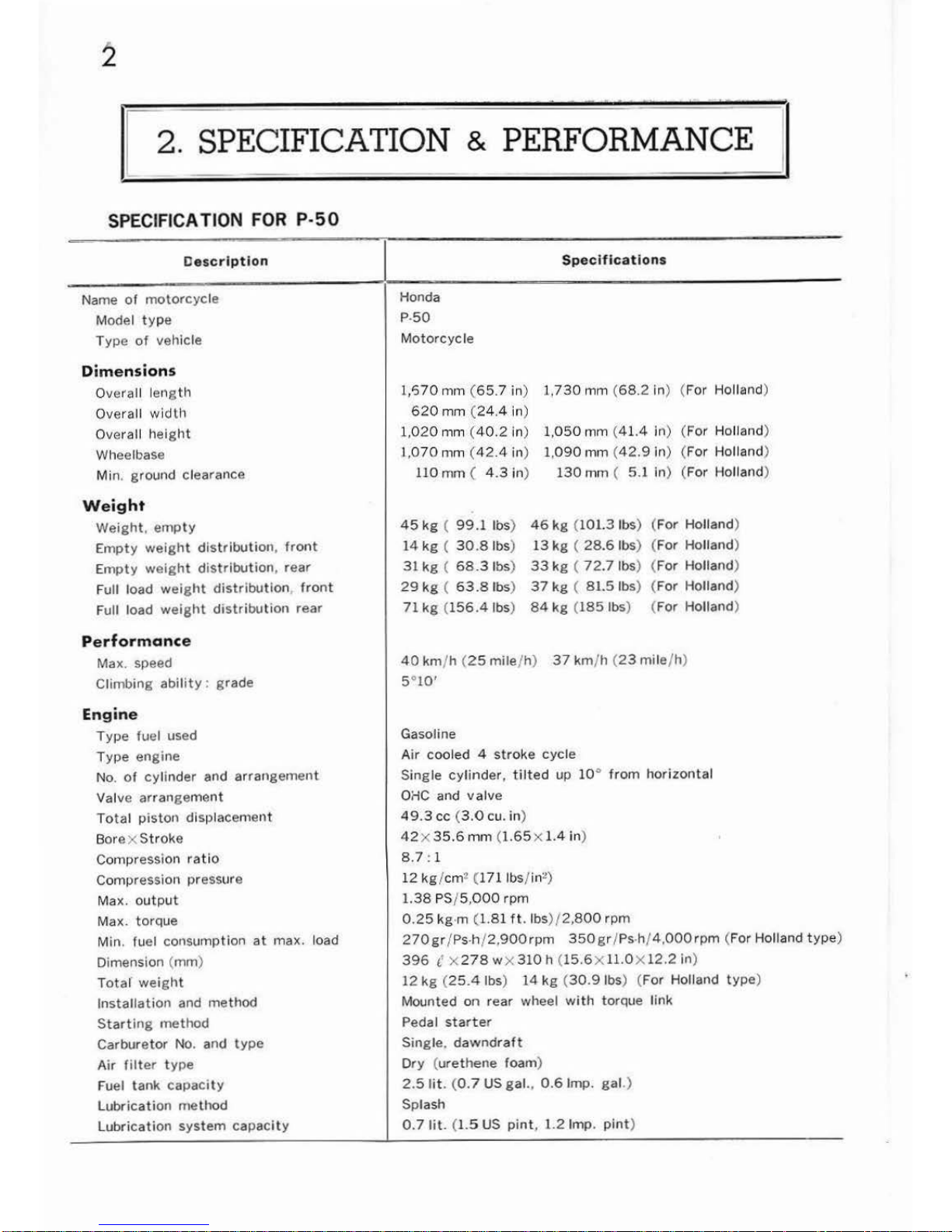
r 2. SPECIFICATION & PERFORMANCE
1
SPECIF
ICATION
FOR
P-50
De
scr
ipti
on
Name
of
motorcycle
Model
typ
e
Type of
vehicle
Dimens
ion
s
Overall ler1g th
Overall wi
dth
Overall h
eight
Wheelbase
Min. ground clearance
Weight
Weight, empty
Empty
weight
distribution, front
Em
pty
weight
distribution
, rear
Full load
weight
distributio
n,
front
Full load
weight
distribution
rear
Perform
once
Max. speed
Climbing
ability: grade
Engine
Type
fuel used
Type
engine
No.
of
cylinder
and
arrangement
Valve
arrangement
Total
piston
displacement
Bore x
Stroke
Compression
ratio
Compression pressure
Max.
output
Max. torque
Min.
fuel consumption
at
max. load
Dimension (mm)
Totar
weight
Installation
and
method
Starting
method
Carburetor No. and
type
Air
filter type
Fuel tank
capacity
Lubricati
on method
Lubrication
system
capacity
Spec
if ications
Honda
p.
so
Mo
torcycle
1,'570
mm (65
.7 in)
1,730
mm (
68.2 in) (For Holland)
620
mm (24.4
in)
1
,02
0 mm (40.2
in)
1,
050
mm (
41.4 in) ( For Holland)
1,070
mm (
42.4
in) 1,090
mrn (
42.9in
)
(For
Ho
lland)
110
mm ( 4.3 in)
130
rnm ( 5.1
in)
(For Holland)
45
kg ( 99.1
lbs)
46
kg
(101.3 lbs)
(For Holland)
14
kg ( 30.81bs
)
13
kg ( 28
.6 lbs)
(For Holland)
31
kg ( 68.31bs) 33
kg ( 72.7
lbs)
(For
Holland)
29
kg ( 63.8
lbs)
37
kg ( 81.5
lbs)
(For Holland)
71
kg (156.41bs) 84
kg (185
lbs)
(For Holland)
40 km/h (
25
mile/h)
37 km/h (
23
mile
/h)
5°10'
Gasoline
Air
cooled 4
stroke
cycle
Si
ngle
cylinder, tilted
up 10°
from
horizontal
o;;c
and
valve
49.3
cc (3.0
cu. in)
42 X 35.6
mm (1.65 X 1.4 in)
8
.7
:1
12
kg /cm
2 (1
7llbs
/ in2)
1.38 PS/5,
000
rpm
0.25
kg·m (1.81
ft
. lbs
)/
2,800
rpm
270
gr /Ps·h/
2,900
rpm
350
gr / Ps·h/
4,000
rpm
(For Holland
type
)
396
c x
278 wx310
h (
15.6xll.OX12.2 in)
12
kg (25.4 lbs) 14
kg (30.9
1bs) (For Holland
type
)
Mounted
on
rear wheel
with
torque link
Pedal
starter
Single,
dawndraft
Dry (urethene
foam)
2.51it. (0.7
US
gal
..
0.6
lmp.
gal.
)
Splash
0. 7 lit. (1.5
US
pint
, 1.2 Imp.
pint
)
Description
Ignition
system
Ignition
method
I
gnition
coil
Type
spa
rk plug
Power
transmission
system
Prima
ry
reduction
method
Reduction
rat
io
Clulcil
type
Secondary
reduction
method
Reducti
on
rat
io
Steering
system
Steering
handle turning radius
Steering hand
le
width
Caster
T
rail
Tire,
fron
t
Tire, rear
Brake
system
Ty
pe
brake, fron
t
Type
brake,
rear
Met11od
of application, fro
nt
Method
of
appl
icat
ion,
rear
Suspension
system
Suspensi
on method,
front
Lighting
system
Headlight rating
Ta
illight
rating
Stoplig
ht
rating
Fl
ywheel magneto
Hi
gh
voltage
A.C.
C
·6
HB
Sprocket and chain
2
.74
: 1
Centrif
ugal automat
ic
Specifications
Sprocket
and
chain
(Gear
for
Holland
type)
6.25
: 1 (
6.95:
1 for Holland
type
)
75
°
5
70
mm (22.4
in)
66
°
40
mm (1.
58
in) , (
50
mm (1.
97
in)
for
Holland
type
]
2.00.
17 (2P
R) (23-2.
00 for
Holland)
2.
25
·17 (2PR) (2
3·2.
25
for
Holl
and)
Expanding
bra
ke shoe
E
xternal clam
ping shoe
R
igh
t handle
lever
L
ett
handle leve
r
Spring
6V·l5W (For
U.S.A.
type
)
6V-10W (For
General
expo
rt, England
type
)
6V-6W (For
France,
Belg
ium,
Holland
type
)
6V-15W
(For
Germany type)
6V-5.3W
(For U.S.A. type
)
6V-3W (For
General
export. Eng
land
type
)
6V-1.8W (
For
France, Belgiu
m.
Holland
type
)
6Y·l.8W (For
Ger
many
)
6V-17W
(For
U.S.
A.
type
)
6V-8W (For
General
export, England
type
)
bV-5W
(~or
~ranee.
Belgium
type
)
3
4
DRIVING PERFORMANCE CURVES
3
8 X 10
15
7
,.....
:E
6
,.....
I:L
0)
..:.::
~
-
5
10
Q)
-
u
..
.,
0
Q)
4
1.&..
4»
Q.
0)
UJ
c
Q)
3 >
c
5
..
en
2
c
c
I.LI
1
0
10
20
30
40
50
Running Speed
(km/hr)
ENGINE PERFORMANCE CURVES
1.5
0.4
Q)
:I
IT"
0.3
o E
~·
01
0.2
.::~
ns
~
.:
,....
0
cri
1.0
0.1
0.:
~
-
:I
ca.
-
:I
0
-
-
600
ns
.c
c
0
0
500
·.;:
ca.,....
E~
0.5
400
:I
'
tJj tJj
c
ca.
o
.......
300
0
..
01
4)~
:I
200
LL.
2 3
4
5
6
7
X 10'
Engine
Speed (R.P.M.)
(
General,
England,
Belgium, France
and
U.S.A.
export
type
)
7
6
5
4
3
2
0
1.5
u)
a.:
-
1.0
c:
.2
•
•
·e
ell
c
CG
..
t-
-
-
:I
D.
-
:I
0
0.5
2
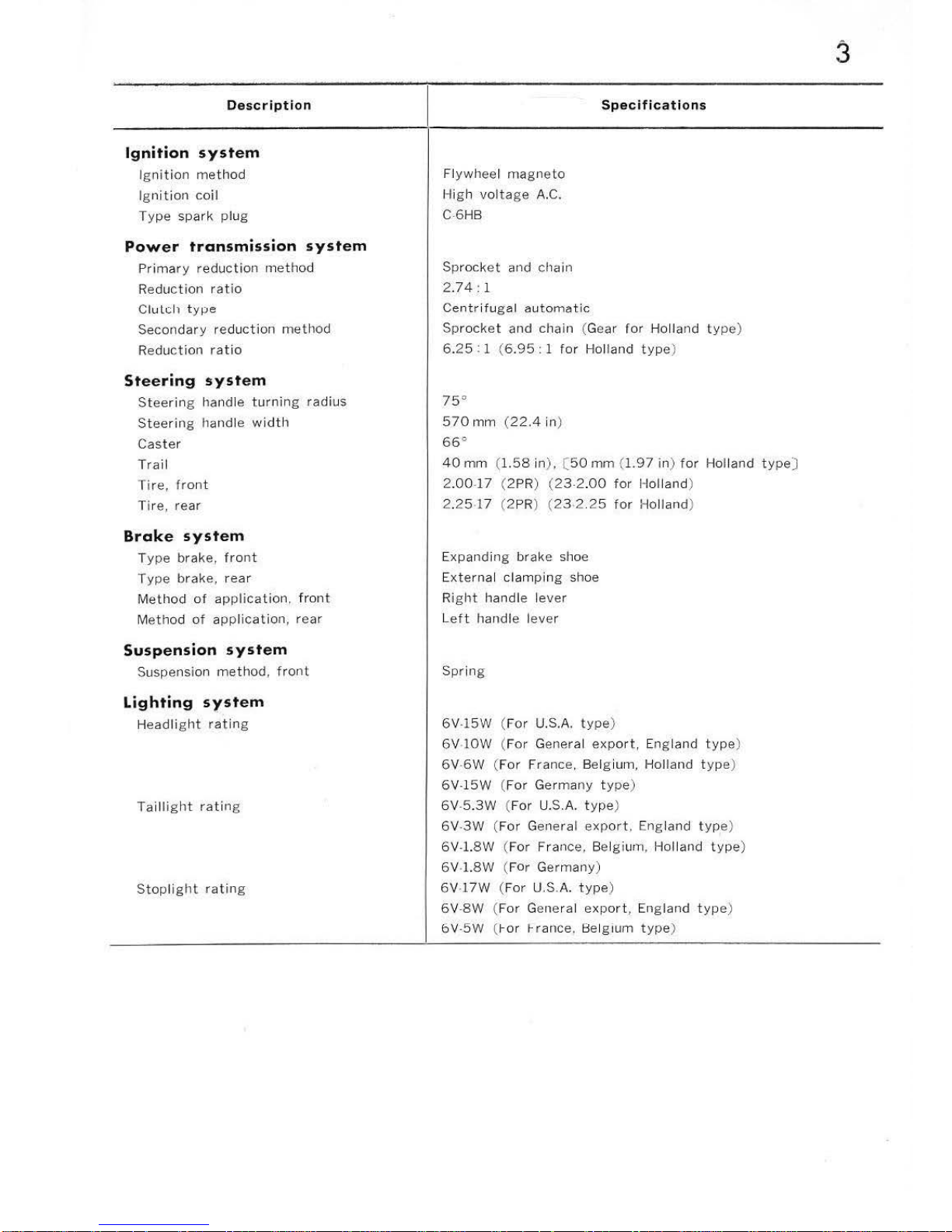
DRIVING PERFORMANCE
10
20
30
40
Driving
Speed
(Km/Hr)
ENGINE PERFORMANCE CURVES
3 4 5
6
Engine Speed (R.P.M.)
(
For
Netherlands
export
type
)
5
50
0.4
-
E
.
0.3
01
~
-
0.2
41
:I
CT
..
0
0.1
t-
-
..
..c:
.
Cll
D.
700
.._
..
01
-
600
c
0
·.;;
500
D.
E
:I
"'
400
c
0
0
300
Qi
:I
1.1..
7 X
10
3
R.
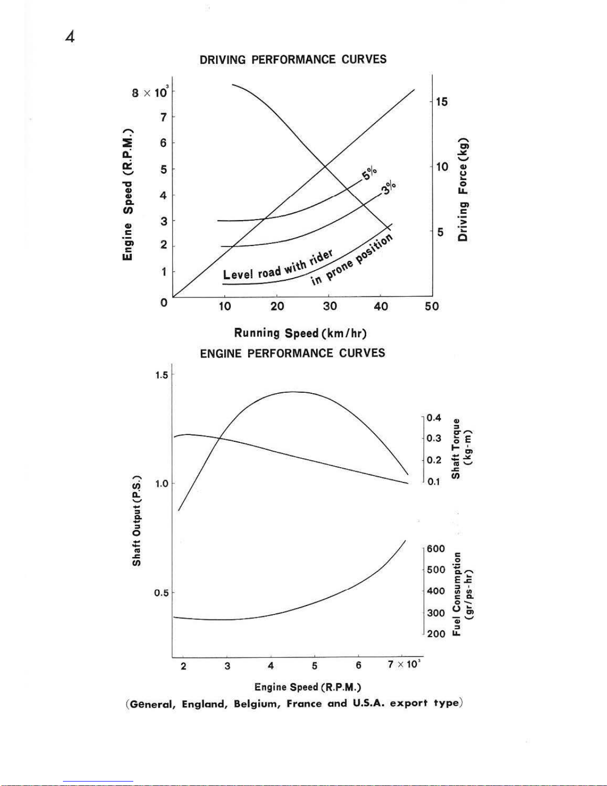
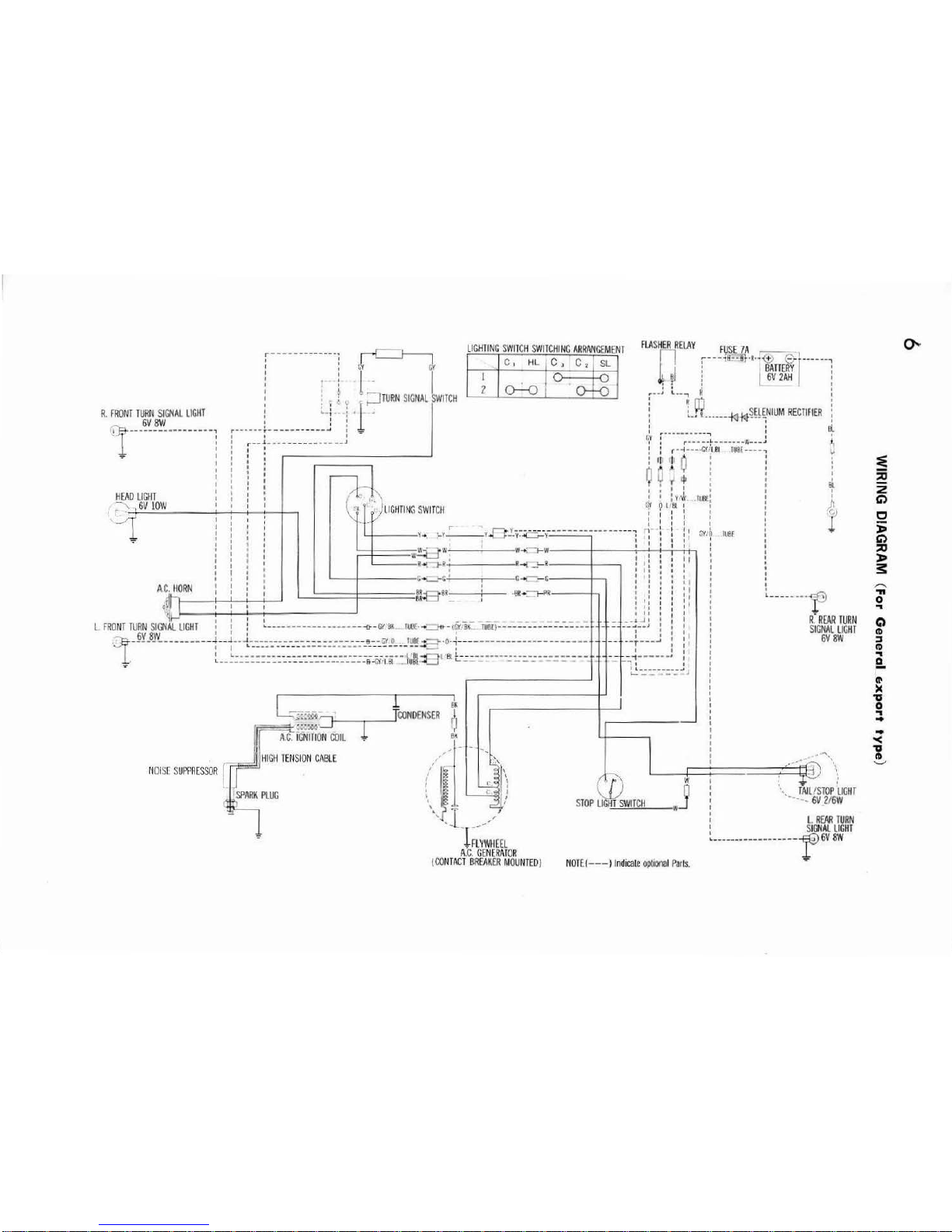
FRONT TURN SIGNAL
LIGHT
1
--
-
~~~'!!
_____
-----,
I
I
I
..- I
I
H
EAD
liGIIT
·,~
6V
l
OW
:-------------
]
~
: : l· · I
i , ,
;=J
TURN
SIG
NAL
SWITCH
.
I
I
I
o I
r------
r------
-----~
. '1'
o I
r--J
........
........
.............
J
l
']::i§ml'
FLASHE~RELAY
F
USE
7A
__
1
r
!
:-
--~~l!l-·R·-l1A
m~-
r---
---:
~
i
W2~
:
o • I . I
"'
__
; L ...
..,
R !
l
UQ
···-
--~
~
~~~
~NIUM
RECTIFIER
i
: :
It~
"r :----·;_
..
_-_-~
~
-------w--
-J
~
! : r · -1···-G\''18
tusr ----
1
1-
:I
I I 0 : :
0
~
,t : I
y f
"'
I :
I I I I t I
! I :
yrk
.fUB(:
:
~"'!
9
l7!t ~ : :
: : : : : :
n ~ : : 1
~v
,o
ru
er
~
I 1 I 11 I I
sl
I
J;)
l
• I I I I : :
W~~W'--------~~--
------
:~~:~:--rr-T;T~l~
1
1
I
-r
-::;-t • I ! : :
L----t--
---------~·---G'
c~---c
------
--+--.
AC. IIORN
I I : i I I
fiR
~~~~-~
I , , 8
..
~
\....--
f-.:
1 I I I • _ _ _
L
FRO
NT
TURN
SIGNAL
UGH
I I I :
•----
---------------~-
C'I
BK
IUil'·- _
.,..(GY
B~
TU8[)---
----
---
----
----
6V8W
I I '
·
1,·--------------t~t:;~~~~~~~~~~~~~~-~~~
~~~=~~
~:~~~~:=~~;:~
:
:t~~=~~~~
---~~~~~~~;~~~~~=
81 I ·
l:tt
•...,...,R
---
---1--,
r-
- I
Bt
_l:_=
~~=
::::J
J
<XJNDEHSER
f
~
J
f
Al"
i~NITION
<Xlll
r e'
l
HIGtl TENSION
CABL
E
- ,
N
OIS[ SUPPRESSOR
.
'-?l /
, -r;;;W
IIE£L
I
I
I
I
' I
I I
I I
I t
_
....
--'
II
-- ~-
..
J
I
I I
--r---
-'
I
-1------
.
I
~---
-----p
R.
REAR
!URN
S
IGNAL
liG
HT
GVF:W
...,_
' t
~:::..---:-.:
_,
.j
I 1 ;
.···£0
"',\.
W I •
1
;
j
; \
TAIL/STOP
LIGHT
I - •
·-
6V
2f6
W
1
11
~nll\.111
W
1
; L
REAR
TUR
N
; S
IGNAl
UGH
I
A.
C.
GENERAIOR
!CONTACT
BREAKER MOUNTED)
NOT
E(---
) l
ndicalc optiOnal Paris.
•--·-···
----------
-r6V
aw
:E
$
2
G')
c
;;
G')
:::0
l>
s:
.........
'II
0
..
Q
~
:::s
II)
..
e.
(II
)(
'U
0
..
..
..
"<
'U
It
"'-"
0..
3
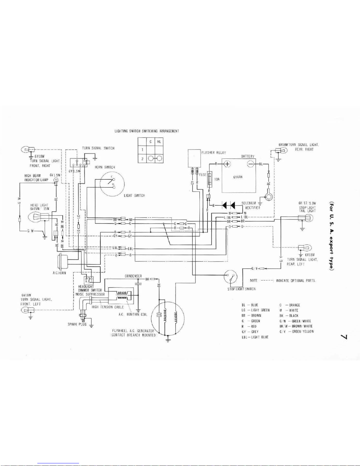
LIG
HTI
NG
SWITCH SWITCHING ARRANGE
MENT
~
6VI81¥lUR
II SIGNAL LIGHT
~
-------
TU
RN
SIGNAL SW
ITC
H
r~
RU R RIG
HT
I
FLASHER REL
AY I
_
6Vl8W
1
BATTER\
'-·
- I I -
TURN
SIG
IIAL
LIC
HT
: R Q Bl
FRON
T. RIGH
T
~
IIO~fl
Sl'
li!
C~
f l
HIGH
BEA
M
6V I 5W
1
FUSE
6V4AH
IH
OICAIOR LAMP
(ill
l :
>-
R
lOA
~
l : : R
~
a:>
I I I
L-:-
~
I
"'
~a>
I I I T
SWITCH
~
0
i i J I SELE
NIUM
- l
I : : R
~
~
I!:J
RECTIFIER
- I
I I ...
~
R I
I I I
Y/
\'/
I
~ : ~
:
.----
-----.,
r-L'B
L~l
BL
-----
---.J
~
I 1
~
1
BR
BR
1 BR-c::>-BR
=-I
1 I G
--=-G
, G-c>-G -
""
I I I \
0~·0-
---------,
cc
I I I ! l \ L R
-<:J-R
- J
--
-
1-1-··1
I
n : l
~
:
ER
--=-
R ·
--
· . I
""
L\ t::=' I
G W
6V
17 5
3W
S
TOP
LI
CHl
f
All
LIGII
T
":"
6VI8W
TU
RK
SIG
M L
LIGHT.
FRONT LEfT
)
Lr~
-
1
__
i _
___
-----
cv-
c::r-
cY
\ I :
,:
I I I I
I I I
I
'-{-
_:::
t _·:::::.-
:::::·LBL::B-LBL
• :
L-
------
~
I l
r
---
0·
..._-----
0
:
L_
____________
·-
..
-----
~w
:
TURN
S
IGNAL
LIGHi
I
I
I
I
RE
AR
UFT
y
-<=!
._.. _ __,_
_ J
BK
j
--
---
INDICATE
OPTIOnAL
PART
S.
"'
ST
OP
LIGHT
S
WIT
Cil
Bl
Blll
0 -
ORANGE
~
----------
---
\
A.C. IGNITIO
N COIL
LG -LIGHl
GRHN
BR -BROWN
W W
HITE
BK -BLACK
-=
FLYWHEEL
A. C.
GENERATOR
·
CONTACT BREAK
ER MOUNT
ED
':"
G -
GREEN
R -
REO
GY
-
GREY
LBL
-
LI
GHT
BLUE
C W
CREE
~
WHil
E
BR
'W-
BROWN WHilE
G Y -
GREErl
YELLOW
..-....
"'
0
"I
~
~
,.
(D
)C
'U
0
:t
....
'<
'U
CD
'-"
"'
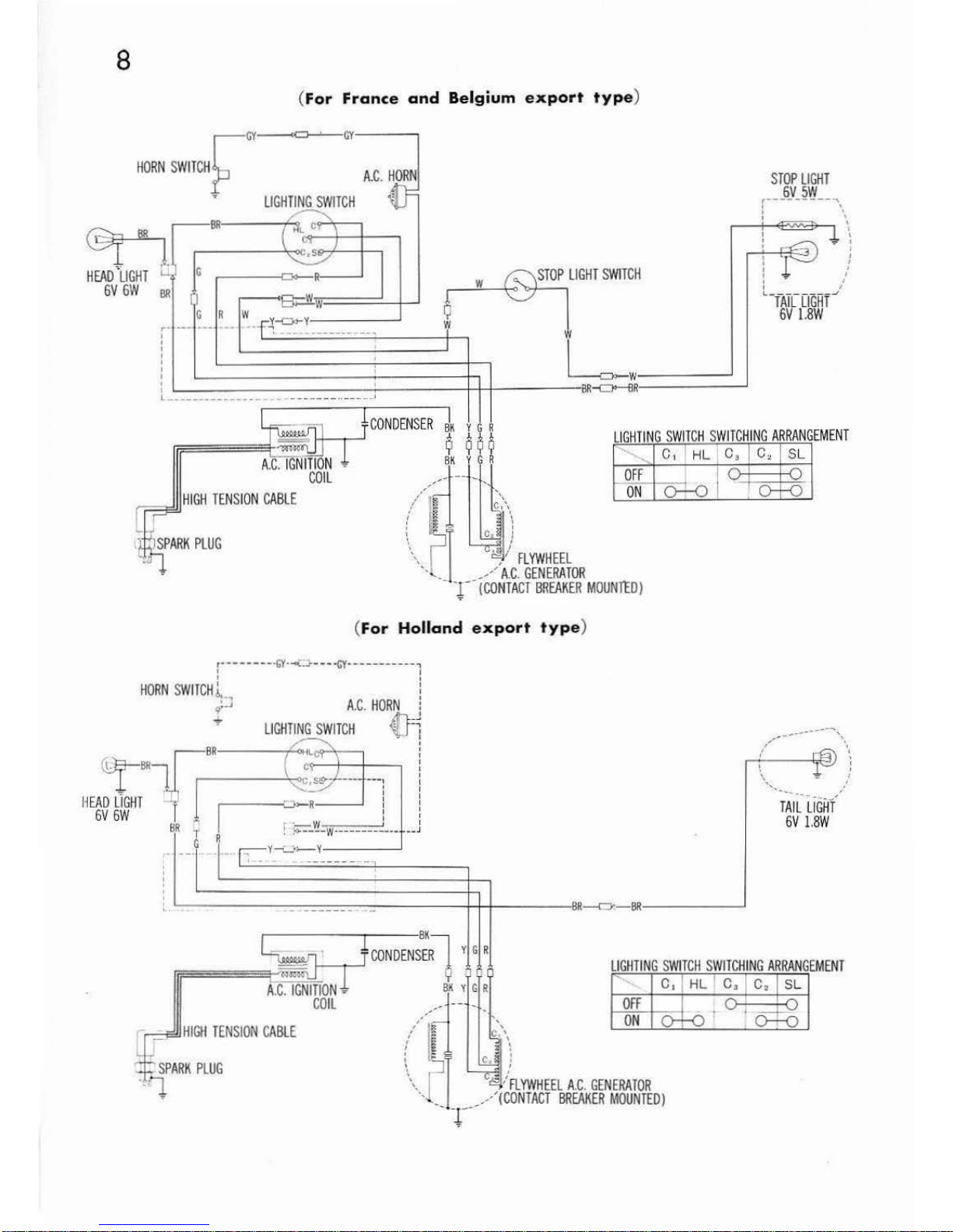
8
(
For
France
and
Belgium
export
type
)
HOR!iSWITCH
~
0
LIGHTING
SWITCH
<CJ ·
cv
- - ---,
A.C. HORN
HI
GH TEN
SIO
N CABLE
(
For
Holland
export
type
)
STOP
LIGHT
6V
SW
,----
-----
""'\
: \
' '
'
! /
0 I
"T
AILLIGHT""
'
6V
l.8W
'
'-------:
_
;--:-:
__
:::_=-
-=-=-=
-
~--
---
-W-
+-----BR
---c:=r-
BR'---
-.....1
~
-
f
BK
~~~
.
CO
NDENSE~
y G R
C
i!hmrON
~
z Y G R
LIGHTING SWITCH SWI
TCHING
ARRANGEMENT
,,
c,
CO
IL
rl
- -- _
Off
ON
-
o-
- _
HIGH
TENS
ION
CABLE
//~;
~ • ~\
:
~-
lJ
:
\.
pT 4 /
FLYWHEEL
A.C. GEN
ERATOR
.
.... _Jf'
/
(CONTACT
BREAKER
MOUNTED)
HL 1 C,
I
c.l
SL
f-0
'
~
(
For
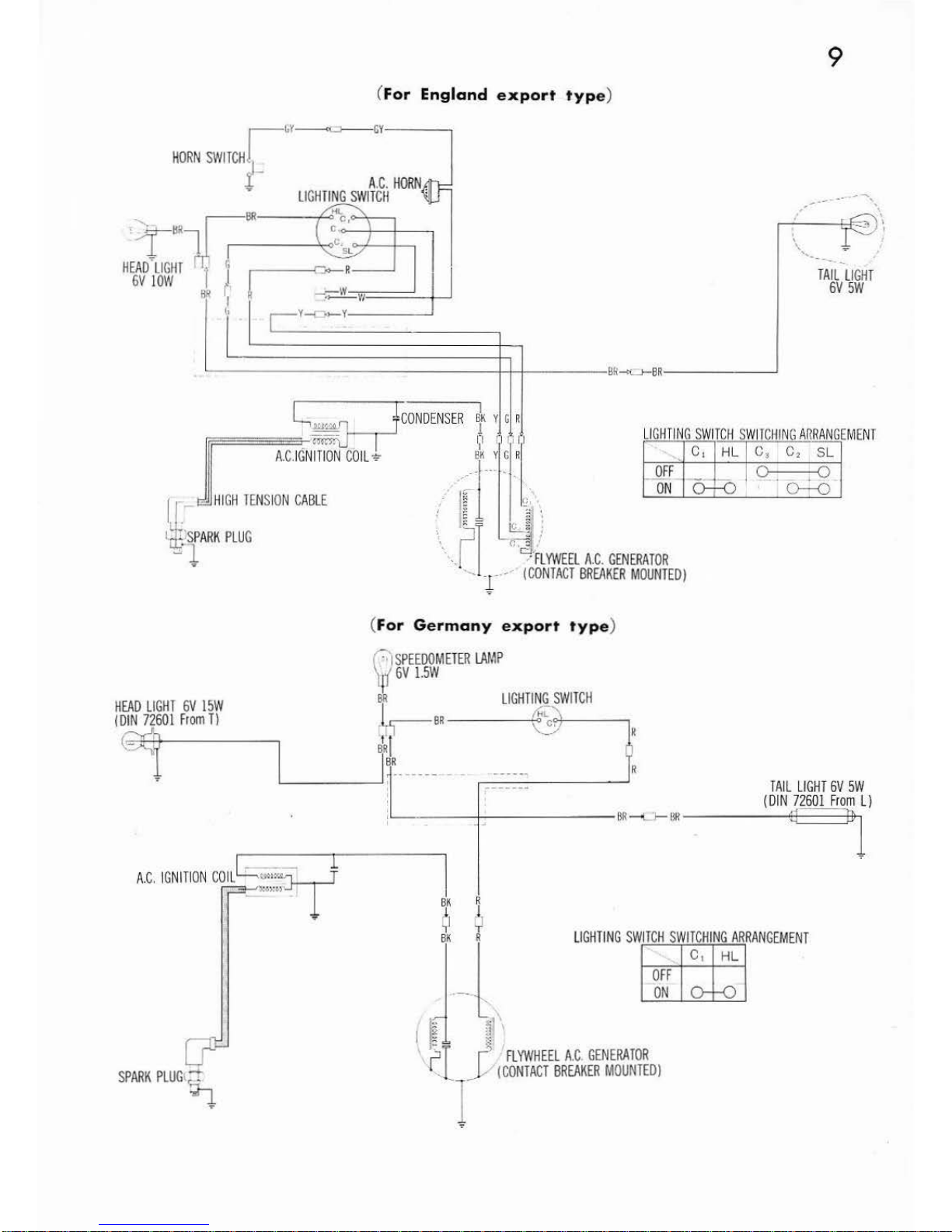
England
export
typ
e)
r
Y-=>----GY
HORN
SWITCH
]_
I A.
C.
HORN,
y
LIGHTING
SWITCII
·:
'
)-BRl~
-BR
~
HEAD~
LIGHT
1 l
9
,'
\
.----f:::F=
--~
...
-
~
\
'•
...
_-
....
--
TAILLIGHT
6V
SW
GV
lOW
ll>ll
j
~
J.___v--r_-
~_=-_:
_,.,
____
_
------
-
----\-/-t
----
BR-«.J-8R----__J
l~
I f
co
NDENS
ER
~
K
v G R
~====::s--~-cmi,-
n o
11
1
A.C
IGNITION COIL
9
~K
Y G R
I
HI G
il
!EliSION CABLE
, ,
·i
d .....
~
,
J-
G1-SPARK
PLUG
;_::J
:::::14
~-l
, .j
"·
c:3'mWEEL
A.
C.
GENERATOR
.
·--
r···
(CO
NTACT
BREAKER
MOUNTED)
(
For
Germany
export
typ
e)
0)
SPEEOOMETER
LAMP
4'f
6V
l.SW
~
~
-
HEAD
LIGHT
6V
ISW
I
DIN
72601
From
Tl
BR
LIGHTING
SWITCH
-
h-eR
6
~R
s~l
_,
~
G(
!
I
BR
~r
---
--
TAIL
LIG
HT
6V
SW
{DIN
72601
From
L)
BR-L
l--H
R-----4~3-----J:h
l
A
.C. IGNi
fiON CO
IL
C::::
~:;:~
SPARK
PLUG
tM
~
I
BK
R
~J
~
LIGHTING
SWITCH
SWITCHI
NG
ARRANGEM
ENT
OFF
ON
1
J--~
~
'
::SI
r
FLYWHEEL A.C.
GENERATOR
l . _ _ Y (
CONTACT
BREAKER
MOUNTED
)
l
10
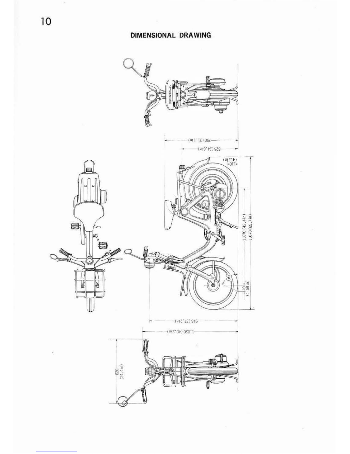
DIMENSIONAL ORA WING
-
--(
U!('(
£/06(-
11
GENERAL DESCRIPTION
3.
ENGINE
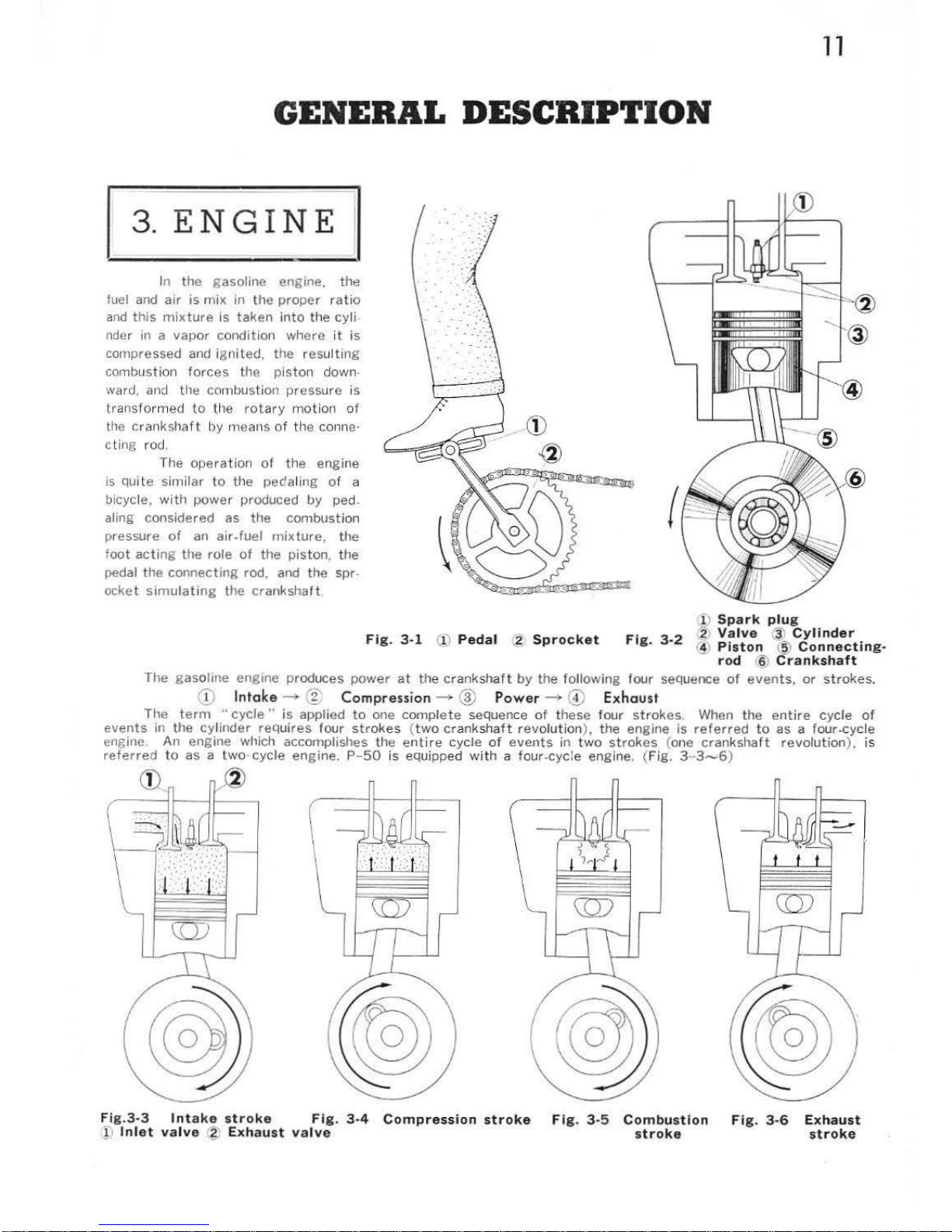
In the gasoline engine.
the
fuel
and
air
is
mix
in
the
proper
ratio
and
this
mixture
is taken i
nto
the cyli
nder in a
vapor
condition
where it
is
compressed and
ignited,
the res
ulti
ng
combu
stion
forces
the pi
ston
down.
ward,
and tl1e
combustion pressure is
transformed
to
the
rota
ry
mot
ion of
the
crankshaft
by means
of
the conne·
cling rod.
The
opera
tion
of
the engine
is
quite simil
ar
to
the peda li
ng
of a
bicycle, with
power
produced
by
ped.
aling consi
dered
as
the
combus
tion
pressure
of
an air. fuel
mixture,
the
foot
acting
the
role
of
the
piston
, the
pedal the
connecting
rod. and
the
spr.
ocket
simulating
the
crankshaft
Fi
g.
3-1
(!)
Pedal
:g
Sprocket
Fig
. 3-2
il
Spark plu
g
2
Valve
'3'
Cylinder
·
~
Piston
t
!?)
Connecting-
rod
~
Crankshaft
The
gasoline engine produces
power
at
the
crankshaft
by
the following four sequence
of
events,
or
strokes.
<D
I
ntake
-+
@:;
Compression
-+
@
Power
---+
@
Exhaust
The t
erm
"cycle"
is
applied
to
one
complete
sequence
of
these four
strokes
. When the
entire cycle
of
events
in the cylinder reQuires
four
strok
es (
two cranks
haf
t revolution
),
the engine
is
referred
to
as a four-cycle
engine. An
eng
ine which accomplishes the ent
ire
cycle
of
events
in
two
strokes
(one crank
sha
ft
revolut
ion
),
is
referred
to as a
two
-cycle
eng
ine.
P-50
is equipped with a four.cyc:e engine. (
Fig
. 3-
3-6)
Cit
,®
Fig.3-3
Intake str
oke
Fig. 3-4
Compression
stroke
Fi
g. 3-5
Combustion
}:
1
Inlet
valve g Exhaust
valve
stroke
Fig. 3-6
Exhaust
stroke
12
Operation
of
the
Four-cycle Engine
The
four-cycle engine
requires
two
reciprocating
sequence
of
the
piston (two
crankshaft
revolutions) to
complete
the
intake
, compression,
power
and exhaust strokes.
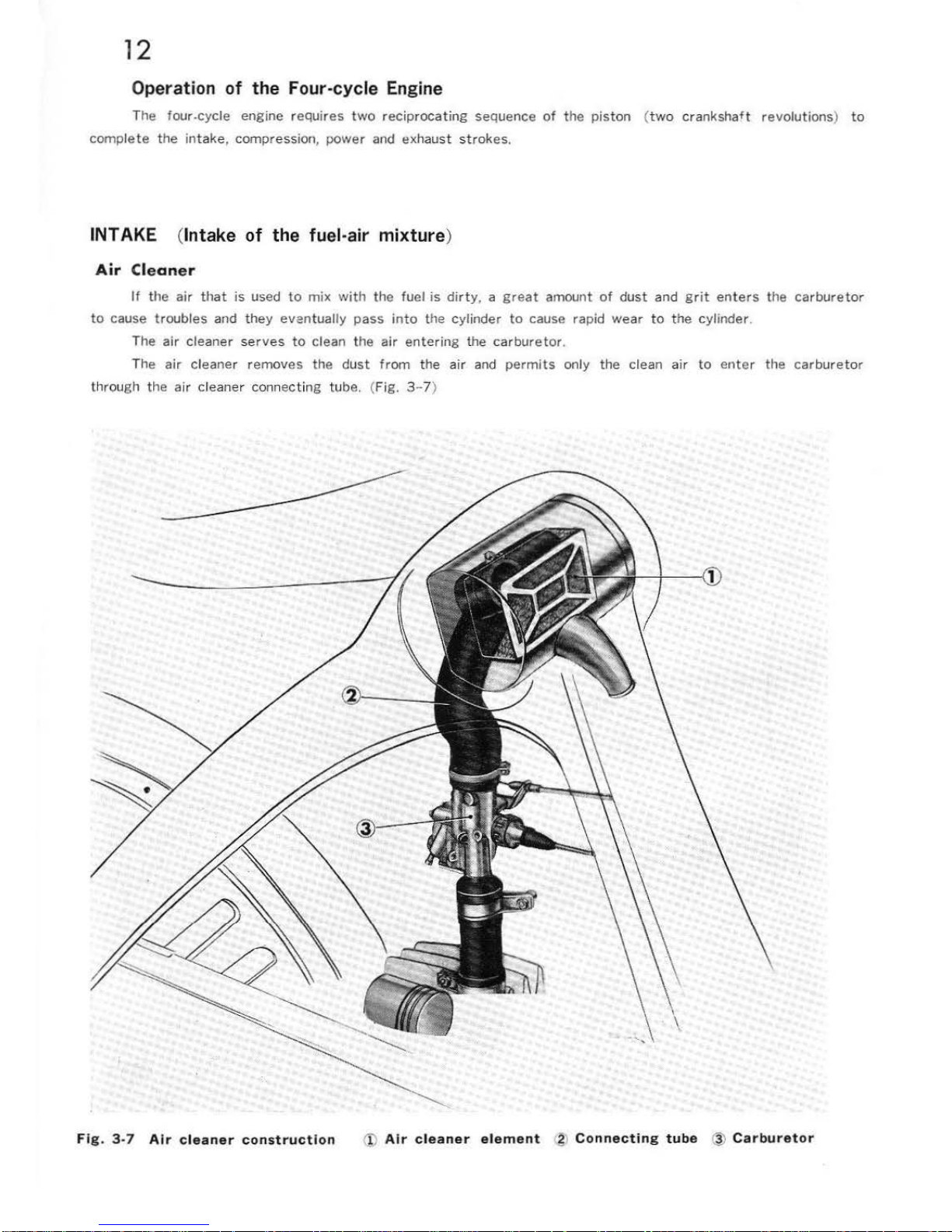
INTAKE (Intake
of
the fuel-air
mixture
)
Air
Cleaner
If
the
air
that
is
used
to
mix
with
the
fuel
is
dirty, a great
amount
of
dust
and
grit
enters
the
carburetor
to
cause
troubles
and
they
eventually
pass
into
the cylinder
to
cause rapid
wear
to
the
cylinder.
The
air
cleaner s
erves
to
clean
the
air
entering
the
carburetor
.
The
air
cleaner
removes
the
dust
from
the
air
and
permits
only the clean
air
to
enter
the
carburetor
through the
air
cleaner connecting tube. (Fig.
3-7
)
Fi
g . 3-7
Air
cleaner
constructi
on
@
Air
cleaner
element
;g
o Co
nnecting
tube
@
Carburetor
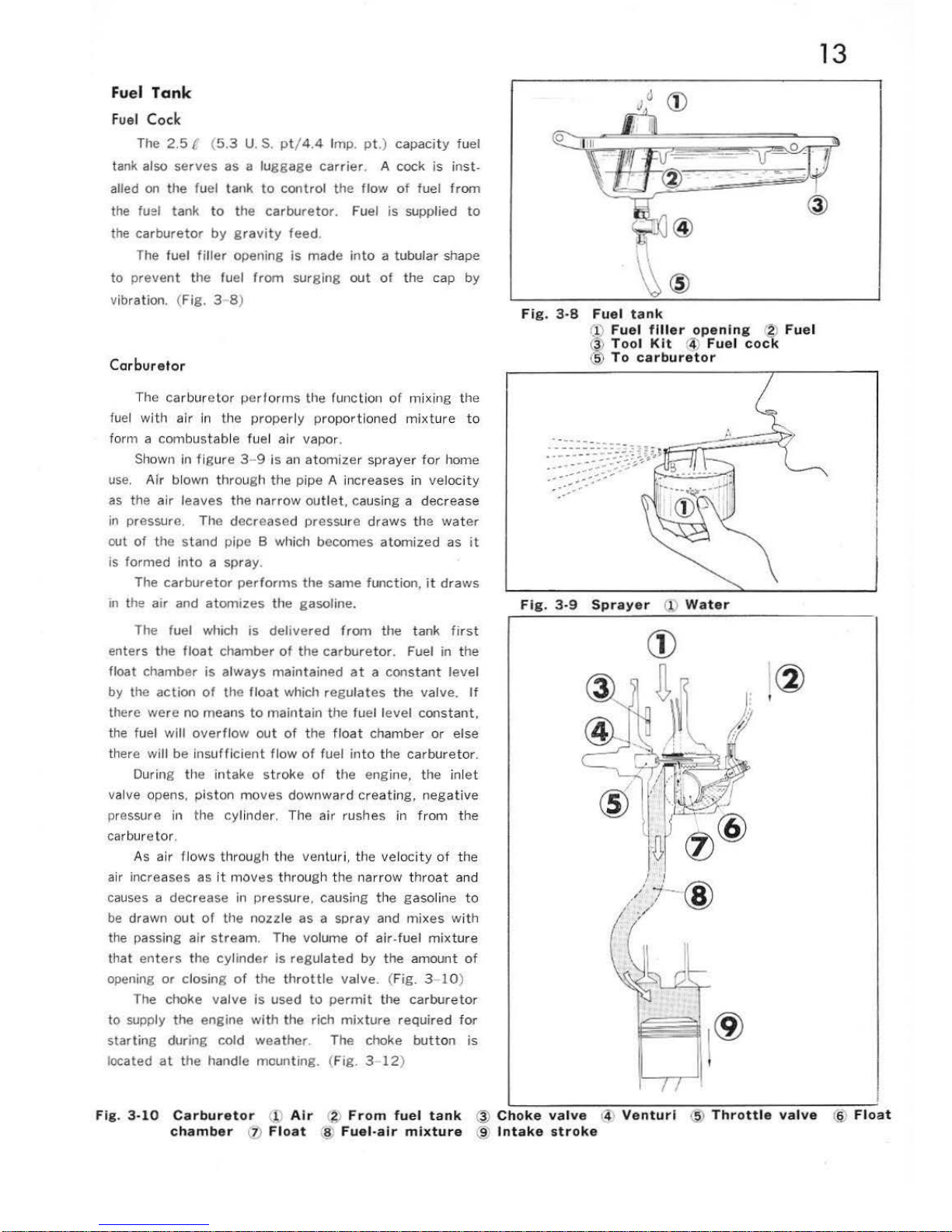
Fuel
Tank
Fuel
Cock
The
2.5
C (
5.3
U.S. pt
/ 4.4 Imp.
pt.
) capacity fuel
tank also
serves
as a
luggage
carrier.
A cock is
inst
-
alled
on the fuel tank
to
control
the
flow
of
fuel
from
the fuel tank to
the
carburetor.
Fuel
is
supplied
to
the
carburetor
by gra
vity
feed
.
The
fuel
filler
opening
is
made
into
a tubular shape
to
preve
nt
the fuel
from
surging
out
of
the cap
by
vibration. (Fig. 3 8)
Car
buretor
The carbure lor
perfo
rms the ru
ne
tion
of
mixing the
fuel with air in the
properly proportioned mixture to
form a
combustab
le fuel air
vapor
.
Shown in figure 3-9
is
an atomizer
sprayer for
horne
u
se
. Air blown
through
the pipe A increases in veloc
ity
as the
air
leaves
the
narrow
outlet,
causi
ng a dec
rease
in
pressure. The decreased
press
ure
draws the
water
out
of
the stand pipe 8 which becomes
atomized
as it
is
formed into
a spray.
The
carburetor
performs
the
same funct ion,
it
draws
in
the a
ir
and
atomizes the gasoline.
The fuel which
is
delivered
from
the tank
fir
st
enters t
he
float
chambe r
of
the
carbure
tor
. Fuel in the
float chamber
is
always
maintained
at a constant
level
by the
action
of
the
flo
at which reg
ulates the v
alv
e.
If
there were
no
means
to
maintain
the
fuel
level
constant,
the fuel
will
overflow
out
of the
float
cha
mber
or
else
th
ere will be ins
uffi
cient flow
of
fuel into the carburetor.
During
th
e intake s
troke of the engine, the inlet
va
lve opens,
piston
moves
downward
creating,
negative
pre
ssu
re
in the
cyl
inder. The
air
rushes in from
the
carbureto
r.
As air f l
ows
through the venturi, the velocity
of
the
air increases as it
mOVtl
S through
the narro
w throat
and
causes a de
cr
ease in pressu r
e.
causing the
gaso
line to
be dra
wn
out
of the nozzle as a sprav and
mixes with
the passing
air str
eam.
The
volume
of air-f
uel mixt
ure
that
ente
rs the cyl
inder
is
regul
ated
by
the amount
of
ope
ning
or
closing
of
the
throttle
valv
e. (Fig. 3- 10)
The choke
valve
is used
to
permit
the
carburetor
to
supply
the
engine
with the
rich mixt
ure
required
for
start ing during
cold
weather
. The choke
button
is
located
at
the handle
mounting
. (Fig. 3-
12
)
13
@
F
ig.
3·8
Fuel
t a
nk
(1)
Fuel fill
er op
enin
g ®
Fue
l
(~)
Tool Kit @
Fuel cock
(5) To
ca
rburet
or
F
ig.
3-9 Sprayer (
l)
Water
'
(2)
'
Fi
g. 3-10
Carburetor
(
!J
Air
r~;
Fr
om
fuel
tank
@
Choke
val
ve
(4\
V
enturi
@
Thrott
le
valve
@ Flo
at
chamber
(?)
Float
~
Fuel-air
mixture
@
Intake
st r
oke

14
@
---
®
5
Fig
. 3-
11
Operation
of
throttle
valve
(_l)
Throttle
grip
rg)
Fuel
@
Carburetor
~
-
Air
@
Throttle
valve
@
Float
valve
®
Float
chamber
@
Float
Fig. 3-12
Operation
of
choke
valve
{I)
Choke
button
@
Choke
cable
@
Carburetor
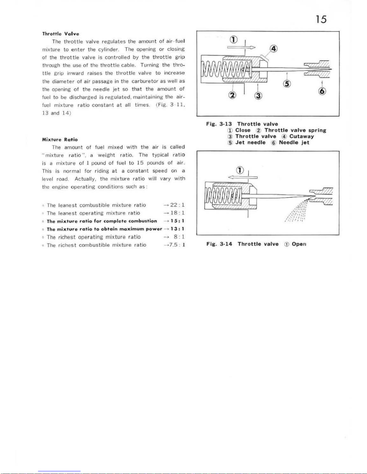
Throttle Vol
ve
The
throttle
valve
regulates
the amount
of air
fue
l
mixture
to
enter
the
cylinder
. The opening
or
closing
of
the
throttle
valve
is
controlled
by the
thrott
le
grip
through the use
of the t
hrottle
cable. Turning the
thro
-
ttle
grip i
nward
raises the
throttle
valve
to
increase
the
diameter
of
air
passage in
the
carburetor
as
well
as
the opening
of
the needle
jet
so
that
the
amount
of
fuel
to
be
discharged
is reg
ulated. maintaining
the air
-
fuel
mixture
ratio
constant
at
all
times
. (Fig. 3
11.
13
and 14)
Mixtur
e Ra t
io
The amount
of
fuel
mixed with
the
air
is
called
·
·mixture
ratio",
a w
eig
ht
ratio.
The typica l ratio
is a mixtu
re
of ! pound of fuel
to
15
pounds of
air
..
This
is
nor
mal
for riding
at a
constant
speed on a
level road . Actually, the mixture rat
io will va
ry
with
the engine
operating
conditions such
as :
The
leanest
combustible
mixture
ratio
-+
22:
1
The
leanest
operating
mixture
ratio
~
18:
1
o
The
mixture
ratio for
complete
combustion
-+
1
5:
1
o
The
mixture
rat
io
to
obtain
maximum
power
> 1
3:
1
•
The
richest operating mixture ratio
The
richest
combustible
mixture
ratio
_, 8 : 1
·7.5 : l
15
~
f
@
Fig
. 3-
13 Throttle
valve
1'>
Close 2
Throttle
valve
spring
3)
Throttle val
ve
(4)
Cutaway
,5)
Jet
needle
1§.
Needle jet
F
ig. 3-14
Throttle
valve
(!)
Open
16
Fi
g .
3-15
Fig.
3-16
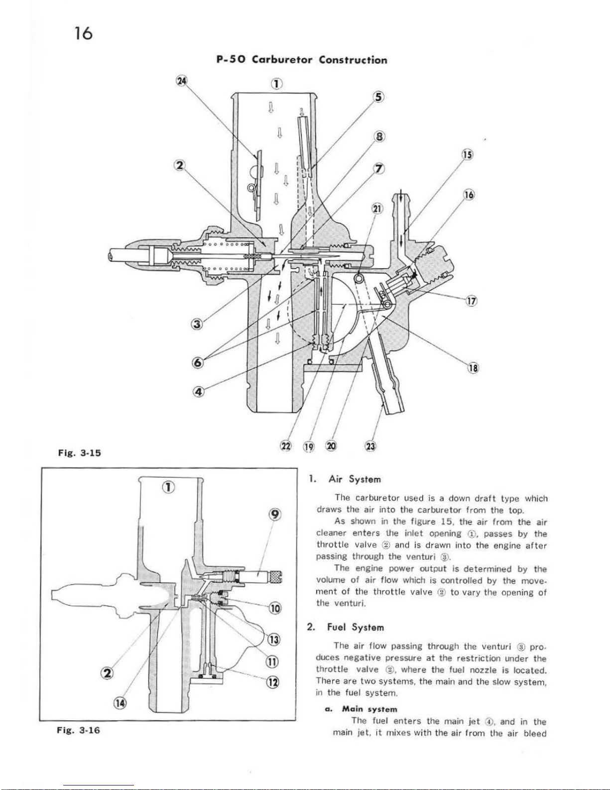
P-
50
Carburetor
Construction
®
1.
Air System
The carburetor used is
a down
draft
type
which
draws the air
into
the
carburetor
from
the top.
As
shown in the
figure
15,
the
air
from the
air
cleaner enters
the
inlet
opening @, passes by the
thr
ott
le valve ® and
is drawn
into
the engine
artor
passing through the ven
tur
i @.
Th
e engine power out
put
is
determined
by
the
volume
of
air
flow
which
is
controlled
by
the move-
ment
of
the thr
ottl
e valve ®
to
vary the opening
of
the venturi.
2. F
uel
System
The air flow passing
thr
ough t
he
venturi ®
pro
.
duces
negative
pressure
at
the
restriction
under the
throttle
valve ®. where the fuel nozzle
is
located.
There are
two
syst em
s,
the main and the slow
system
,
in
the fuel system.
a . M
ain
system
The fuel
enters
the main
jet
'.i),
and
in
the
main
jet.
it
mixes wi th the air from the air bleed
17
:§)
after
the
air
have
been
metered
by
the
air
jet
®. The fuel and
air mix
ture
passes through the opening
between the needle
jet
'!)
and jet needle ®
to
be
discharged
as a spray
at
the
throttle
valve
@. The fuel
spray mixes
with
the main incoming
air
and becomes
atomized
before
being taken
into
the engine.
b. Slow
system
The air which
enters
from
the
inlet
opening
1;
passes around the outside
of
the
air
screw
® where
it
is
metered
and then
enters
the bleed hole @
of
the
slow
jet
~-
On
the
other
hand.
the
fuel
from
the
float
chamber
after
being
metered
by
the
pilot
@ and
metered
again
at
the
jet
area @
of
the slow
jet
iii. mixes
with
the
air
from
the
bleed hole ®
with
in the slow
jet
and
is
discharged
at
the
bottom
of
the
throttle
valve
'-~
from
the
pilot
outlet
@,
to
mix
with the main
flow
of
air
from
the
carburetor
air
inlet
II'
and
is
taken
into
the engine.
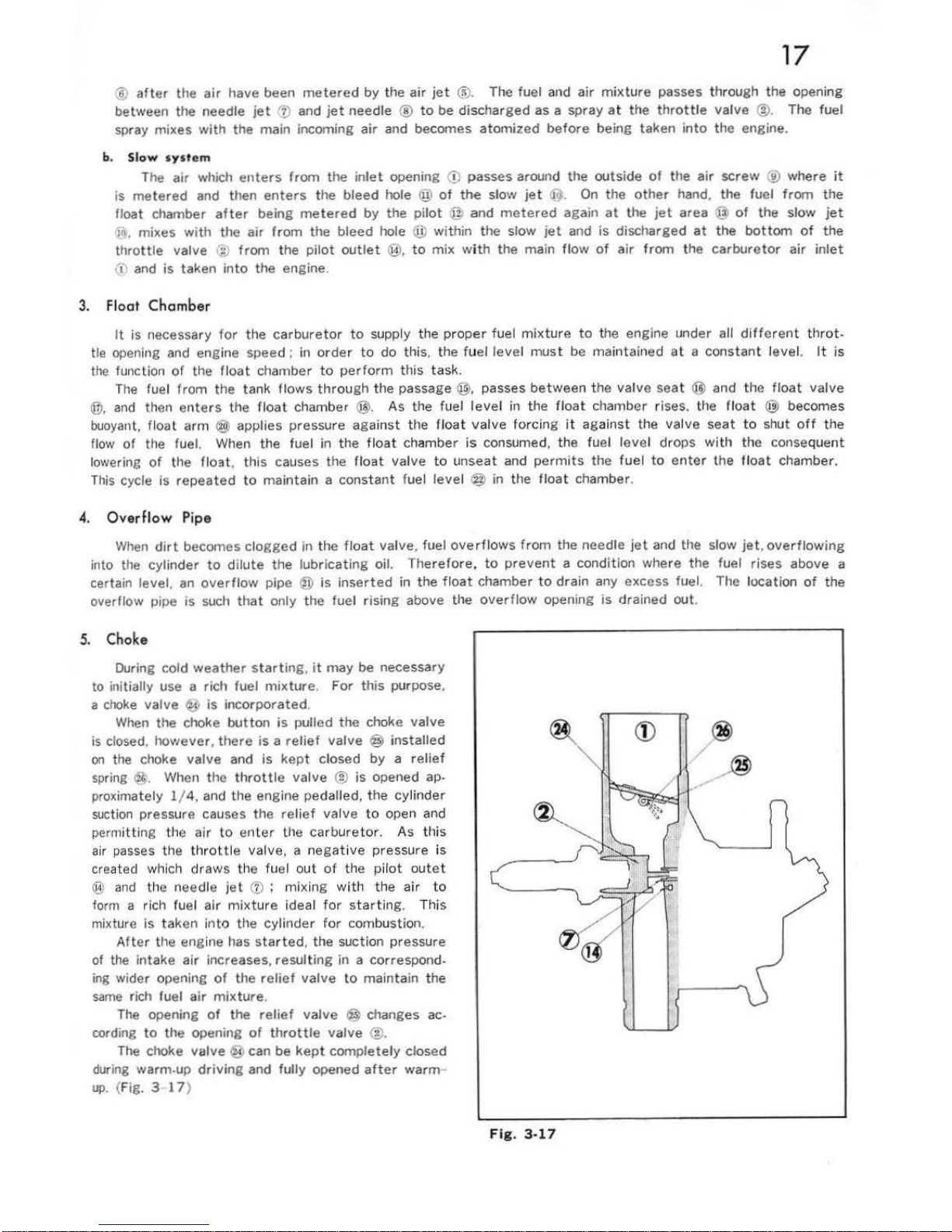
3. Float
Chamber
It
is necessary
for
the
carbureto
r to supply the pr
oper
fuel mixture
to
the engine under all di
fferent throt-
tle opening and engine
speed:
in
order
to
do
this. the fu
el
level
must be maintained
at
a const
ant
level. It is
the
function
or
the float
chamber
to
perform
this task.
The fuel
from
the tank flows
through
the
passage@,
passes
between
the
valve
seat
@ and the
float
val
ve
@,
and
then
enters
the fl
oat
chamber @.
As
the fuel
level
in
the floa
t chamber rises. the
float
@ becomes
buoyant,
float
arm @ applies pressure
against
the float
valve
forcing
it aga
inst
the valve
seat
to
shut
off
the
flow
of
the fuel. When the fuel in
the
float
chamber
is
consumed,
the
fuel
level
drops with the consequent
lowering
of
the flo:st, this causes the
float
valve
to
unseat
and permits
the
fuel
to
enter
the
float
chamber.
This
cycle is
repeated
to
maintain a
constant
fuel
level
@ in the float chamber.
4.
Overflow Pipe
When
dirt
becomes
clogged
in the
float
valve. fuel
overflows
from
the needle
jet
and the slow
jet.
overflowing
into the cylinder
to
dilute
the
lubricating
oil.
Therefore.
to
prevent
a condition where
the
fuel rises above a
certain level.
an
overflow
pipe ®
is
inserted
in the
float
chamber
to
drain any excess fuel. The location
of
the
overflow pipe
is
such
that
only the fuel
rising
above the
overflow
opening
is
drained
out.
5. Choke
During cold
weather
starting, it
may
be
necessary
to
ini
tially use a rich fuel
mixture. For
this purpose.
a
choke
valve ~ is
incorporated
.
When
the
choke
button
is
pulled
the
choke
valve
is
closed.
however, there
is a relief
valve @ installed
on
the choke
valve
and
is
kept
closed
by a relief
spring
@.
When
the
throttle
valve ® is
opened ap.
proximately
1/
4.
and the engine pedalled,
the
cylinder
suction pressure causes
the
relief
val
ve
to
open and
permitting the air
to ent
er
the car
bureto
r. As th
is
air passes the thrott
le valve, a negative pressure is
created which draws the fuel
out
of
the pil
ot outet
@
and
the needle
jet
(i) ; mixing
wi
th the a
ir
to
form a rich fuel air
mixtu
re ideal for sta
rtin
g. This
mixture
is
taken
into
the cylinder
for
combustion.
After
the engine has
started,
the suction pressure
of
the
intake air increases,
resulting
in a correspond-
ing wider opening
of
the
relief
valve
to
maintain the
same
rich fuel air
mixture
.
The
opening
of
the
relief
valve
@ changes ac-
cording
to
the
opening
of
throttle
valve
~
-
The
choke
valve
@ can be
kept
completely
closed
during
warm-up
driving
and fully opened
after
warm
-
up.
(Fig. 3
17
)
Fig. 3-17
®
/
_..®
18
\
Fi
g.
3·
18
Ma
in
jet
•
J,
Genuine
parts
mark
2: M
ain
jet
NO.
3
Fi
g.
3-19
Jet
needle
Ill
Needle
clip
(2
Type
mark
and
genuine
parts mark
,j ,
Jet
need
le
Operation
of P-50
Carburetor
Component
Part
s
1.
Main
Jet
It
meters
the fuel
flow
during full th
rottle
con.
dition (top
speed)
to
provide
a proper fuel
mixtu
re.
Not only
do
es
it
function
at
top speed
but
it
also is
effective
to a cert
ain
degree
at intermed
iate
speed.
The
larger
the main
jet
size number,
great
er
will
be
the nozzle opening and conseq
uently
the fuel flow,
providing
a richer fuel
mixture
. (Fig. 3
18
)
2. Air
Jet
3.
During full
thrott
le
opening. the fuel
mixture
at
high engine speed will become rich. and
at
slow speed
the
mixture
becomes lean.
To prev
ent
such a condi·
tio
n,
air
is
bled
into
the main
jet
to
main
tain a uni
form mixture.
The function
of
the air jet is to
contro
l
the amo
unt of
the bleed
<:~ir
.
As the
air
jet
becomes larger,
the arnollnt
of
ble-
ed
air
is
increased. resulting
in a lean fuel
mixture
,
however,
at
a set
throttle
opening, a high en gine spe.
ed
will
produce a leaner
mixture
There is only a
small
variation
in fuel cons
umpt
ion
between
high and
low
en
gine speed.
Needle
Jet
Dunng
full
or
half
throttl
e opening. the fuel which
had
beet\
metered
by the main
jet
is
again met
ered
by
thd needle jet. The adju
stme
nt
is per formed in
conjucllon
with
the
jet
needle which is
exp
lained in
the
following
section. The needle
jet
openin g
is
made
exceptionally accurate
for
precise
contro
l.
4. J
et
Needle
The
jet
needle.
in
conjuction with the
needle
jet
described
earlier.
regulates
the fuel
mixture
at
the
inter
mediate
throttle
opening (
principdlly
between
1/4
to
3/ 4
throttle
opening). The long ta
pered
jet
needle
is
located
within
the
center
hole
of
the
throt.
tie valve w ith the
tapered
end inserted
into
the
needle jet. The
vertica
l moveme
nt
of
the throttle
valve
to
which the
jet
needle
is
attached
contro
ls
the
flow
of
the fuel in respe
ct
to
the
throttle
open.
ing to
afford a correct
fuel
mixture
ratio
.
There
are
five
clip
grooves
(which
are
counted
from
the top)
on
the head
of
the
jet
needle
to
regulate
the richness
of
the fuel
mixture.
The fuel
mixture
becomes richer as the
clip is
moved
progress
ively
from
the No. 1 g
roov
e to the
No. 5 groove
. (
Fig
. 3
19
)
5.
Thr
ottle
Valve
The funct
ion
of
the
throt tie valve
is
to
control
the amount
of
air taken
into
the engine: this deter-
mines t
he
engine speed. the
power
output
, and in
ilddition.
performs
the important fun c lion
of
controJI.
ing the fuel air mixtu
re.
The
throttle
valve has a
cut
-aw
ay
on
the air
inlet
side
.
Changing the
size
of
the
cut-away (design
ated
by
cut-away No.).
the
pressure
actuat
ing
the
needle
valve
can be
altered
to
change the
amount
of
fuel
flow
and
causes a change
to
the
fuel
mixture. The valve with
a
larger
cut-away
number
will
prod
uce a leaner fuel
mixture.
Howev
er, the
range
of
its
effectiveness is
mainly at
low
speed. from idling
speed
to
approx i-
mat
ely 1
/4
t
hrot
tle open ing and has no
effect
above
1
/2
throttle
opening.
A
thrott
le
stop
screw
sets
the
thrott
le val
ve
in
the
idle
pos
iti
on.
Screwing
in
on
the
stop
screw
will cause the
throttle valve to
rise. and bac
king
off
will
lower
the
throttle
valve.
6.
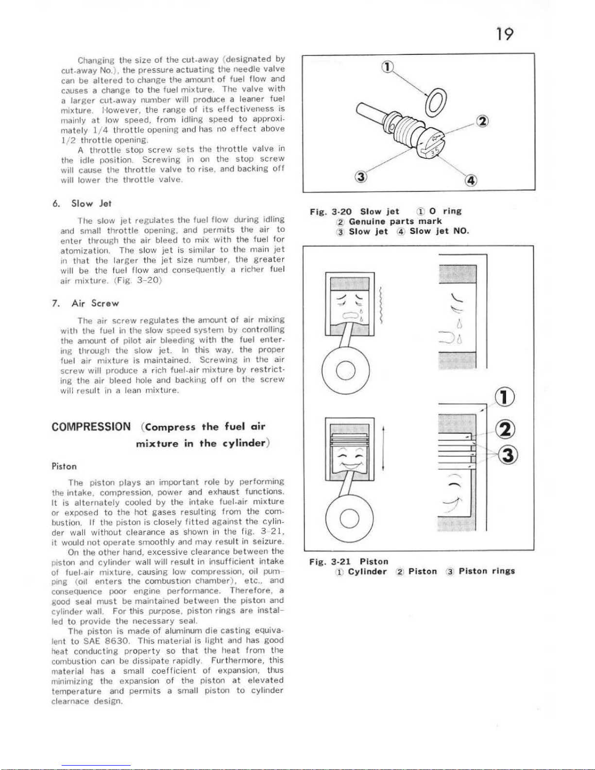
Slow
Jet
1 he
slow
jet
regulates
the
fuel
flow
during idling
and
small
thrott
le opening, and permits t
he
air
to
enter throu gh
the
air bleed
to
mix
with
the
fuel for
atomizat
ion. The slo w
jet
is similar to the main
jet
in
that the lar
ger
the jet
size
number, the
gre
ater
will
be
the luel
flow
and consequent ly a richer fuel
air
mix
tur
e.
(Fig.
3-20
)
7.
Air
Scre
w
The
air
screw
regulates
the
amount
of
air
m1x1ng
with
the
fuel
in the
slow
speed
system
by
controlling
the
amount
of
pilot
air
bleeding
with
the
fuel
enter-
ing
throu
gh
the
slow
jet.
In this
way,
the
proper
fuel
air
mixture
is
mai
ntained.
Screwing
in the
air
screw
will produce a
rich
fuel-air
mixture
by
restrict·
in
g the a
ir
bleed hole and
backing
off
on the scr
ew
will result in a le
an mix
ture.
COMPRESSION
(
Compress
the
fuel
air
mixture
in
the
cylinder
)
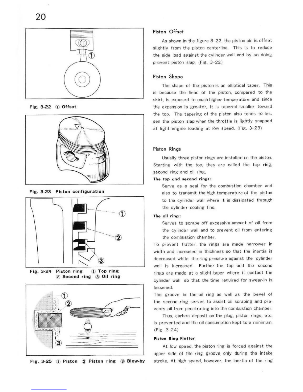
Piston
The
piston
plays
an
important
role
by perfo
rming
the
intak
e,
compression,
power
and exhaust
funct
ions.
It
is alt
ernately
cooled
by
the
intak
e fue l-air
mixture
or
exposed
to th
e hot
gases
resulting fro
m the com-
bustion.
If
the
piston
is
close
ly fitted
agains
t the
cyl
in-
der wall without
clea
ranc e as shown in the rig. 3 2 1,
it
would
not
operate
smoot
hly and
may
result
in seizure .
On the
othe
r hand,
excessive
clearance
between the
piston and
cylinder
wall
will
result
in
insu
ffi
cient intake
of
ruel -air mixture,
causing low compression,
oil
pum-
ping
(oil
enters
the
combustion
c11amber),
etc
..
and
conseQuence
poor
engine
performance.
Therefore,
a
good
seal
must
be
maintained
between
the pist
on
and
cylinder
wall.
For
this purpose,
piston
rings
are
instal-
led
to
provide
the
necessary
seal.
The
piston
is
made
of
aluminum
die
casting equiva-
lent
to
SAE
8630. This ma
teria
l is light and has
good
heat con
ducting proper ty so that
tile
heat
from the
combustion can be
dissipate
rap
idly. Furthermore, this
materia l has a
sma
ll
coefficient
of
expansion, thus
mini
miling
the expansion of the
piston
at
elevated
temperature
and
perm
its
a small
piston
to
cylinder
clearnace
design.
19
Fi
g.
3-2
0
Slow
jet
'!)
0
ring
2
Genuine
parts
mark
'3
Slow
jet
® Sl
ow
jet NO.
l
Fi
g.
3-
21
Piston
11
Cylinder
'2)
Piston
(3
Pist
on
rings
20
Fi
g.
3·22
(!)
Offset
Fi
g. 3-23
Piston
configuration
-
---
®
Fig
.
~-24
Piston
ring
U)
Top
rin
g
@
Second
ring
@
Oil ring
Fig. 3-25
(i)
Pist
on ~ Piston
ring
@
Blow-by
Piston
Offset
As
shown in
the
figure
3- 22, the p
isto
n pin is
offset
slightly
from tile piston centerline.
This
is
to
reduce
the
side load
against the
cylinder
wall and
by
so doi
ng
prev
ent pisto
n slap. (Fig. 3-22)
Piston
Shape
The shape
of the
piston
is
an
ellip
tical ta
per.
This
is
because
the
head
of
the
piston,
com
pared
to
the
sk
irt, is
exposed
to
much
higher
temp
eratu
re
and
since
the
expansion
is
greater, it is tapered small
er
towa
rd
the
top
. The taperi
ng
of
the
pist
on also tends
to
les -
sen the piston slap when the
throttle
is light
ly
snapped
at light
engine loadi
ng
at low speed. (F
ig 3-23
)
Piston Rings
Usuall y th
ree pis
ton rin
gs
are installed
on t
he
piston.
St
arting wi
th
the top,
they
are called
the
top rin
g,
second
ring
and oil ring.
Th e
top
and second
rings:
Serve
as a seal
for the combus
tion
chamber
and
also
to transmit
the
high
temperature of
the
piston
to
the cylind er wall where
it
is dissipated
through
th
e cylinde r cooling
fin
s.
Th
e
oil
ring
:
Serves
to
scrape
off
excessive
amount
of
oil
from
the
cylinder
wall and
to
prevent
oil
from
entering
the combu
stion
chamb
er.
To pr
event flutter.
the
rings
are made
narrow
er in
wid
th and increased
in thick
ness so that the i
nertia
is
decre
ase d while the ri
ng pressure again
st the cylin
der
wall is increased. Fu
rth
er
the
top
and the second
rings are
made
at
a
sligllt
taper
where it
contact
the
cylinder
wall
so
that
the
time
required
for
swe
ar-in
is
lessened.
The g
roove
in the oil ring as
well
as the
bevel
of
the second ring se
rves
to
assist oil
scraping
and pre-
vents oil from penetrat
ing i
nto
the combustion
chamber
.
Thus,
ca
rbon
deposit on
the
plug. pisto
n ri
ngs, etc.
is
prevented
and
the oil consumption
kept
to
a minimum.
(F
ig
. 3 24)
Piston
Ring
Flutter
At l
ow
speed, the
piston ring
is
forc
ed
again
st the
upper side of t
he
ring g
ro
ove
only during the intake
s
troke.
At
high speed, howe
ver
, t he i
nert
ia of the
ring
overcomes the
gas
pressure
and
friction
, and
floats
to the
top
of the
groove
immediately
before
the
top-
dead-center
in the compression
stroke. At
this
moment,
combustion
occurs
and the ring is
forced
again
st
the
bottom
side
of
the r i
ng groove by
the
combustion
pressur
e.
This up and down m
ovement
duri
ng
exhaust-
intake-compression
becomes more and more
intense
coupled
with
the increasi
ng
inertial forc
e.
As
this
seq
-
uence
is
repeated, ult
imately,
the
ring
vibrates
vio
le-
ntly
within
the
ring
groove
like
a pingpong ball
between
the
racket
and the
table
as shown in
the
figure
25
and
thus
allow
the
gas
to
·•
blow-by
". (Fig
. 3-
25, 26
)
Cylinde
r
The p
iston
cannot operate
without
the cylinder.
The
cy
linde r wall
is
exposed
to
high
temperature
and
pressure
togethe
r wi
th the
wearing
action
of
the
reci
procating piston
moving
at
hig
h speed
to
produce a
great
wearing
effec
t.
Therefore.
adeQuate
attention
must
be g
iven
to
the mate
rial
and
construction
of
the
cylinder
as
well
as
the
piston
. The
cylinder
has many
cooling fins on the
outside
so
as to increase
the
heat
di
ssipating
area and
preven
t the cylind
er
and pi
ston
from overhea tin
g.
COMBUSTION
(Ignition of
the
compressed
air-fuel
mix-
ture
by
the
spark
plug
to
cause combus-
tion)
When the
piston
reaches the top-dead-cen
ter
at
the
end
of
the compression
stroke, the
compressed
air-fuel
mi
xtu
re
must
be
igni
ted
.
I
gnition
System
Magneto
sys
tem
a
FlywhP.P.I
magnP.to (
rotating
permanent
magnet
)
b. Box
magneto
P
50
incorporate
s a
flywheel
magneto
(flyweel
AC
generator
).
21
-
co
Fi
g.
3
-26
Fi
g.
3-
27
Cylinder
®
Cooling
fin
s
1-
_@
Fig
.
3-
28
Flywheel
A. C
generator
(!) I
gnition
coil
®
Condenser
@
Hightension
cord
AJ
Spark
plug
cap
@
Spark
plu
g
(61
Pr
ima
ry
coil
(!)
Light
ing
coi
l
~
Ground
®
Contact
breaker
10
H
ead ligh
t .g
Tail/stop light
12
) H
orn
22
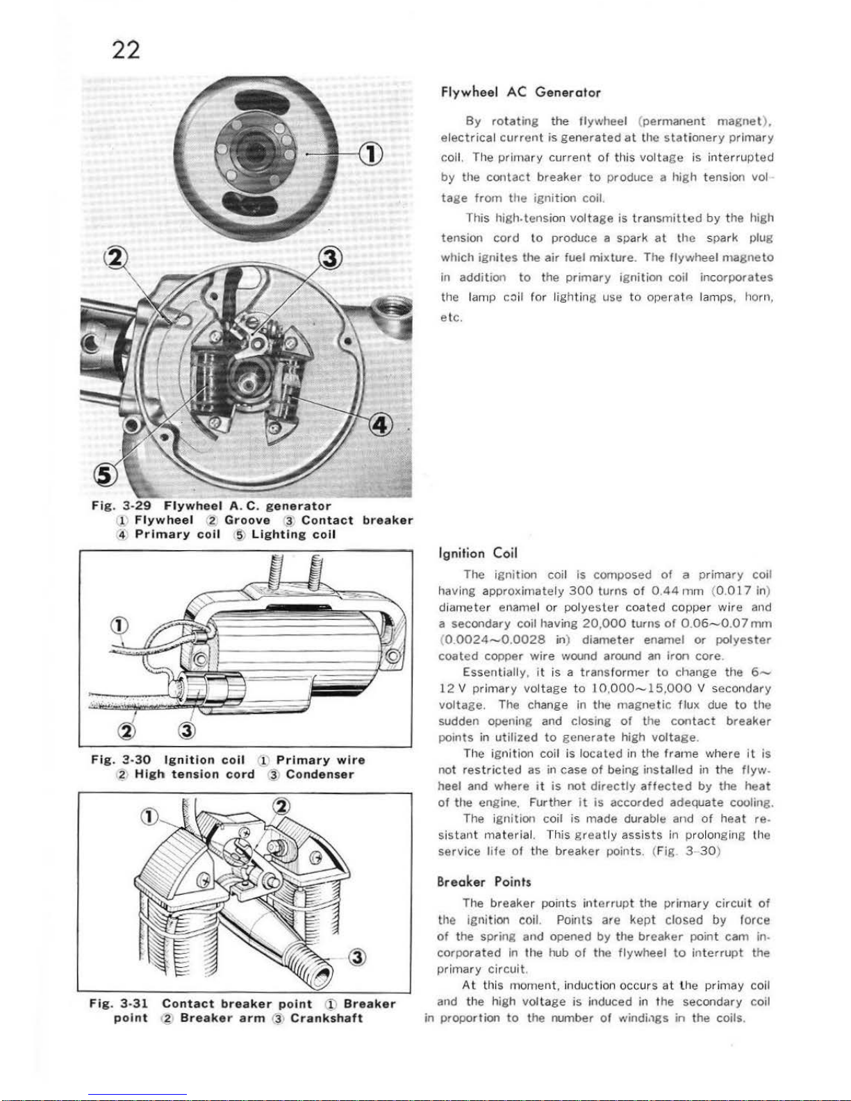
Fig.
3-29 Flywheel
A.
C.
generator
ll Fl
ywheel
,2
Groove
'-
~
Contact
breaker
4
Primary
coli
:
:?')
Lighting
coi
l
Fig.
3-30 Ignition
coi
l (l
Primary
wire
? H
igh tension
cord
j\
Condenser
Fig. 3·31
point
Contact
breaker poi
nt
(i)
Breaker
6.
Breaker
arm
r3,
Crankshaft
Flywheel
AC
Generator
By
rotating
the
flywheel (
permanent
magnet
),
electrical
current
is
generated
at
the
stationery
primary
co
il. The pri
mary
cur
rent
of
this
voltage
is in
terrupted
by
the
contact
breaker
to
produce a high tension vol
tage
from
the
ignition
coil.
This
high.tensi
on volt
age is
transmitted
by the
high
tension
cord
to produce a spark
at
the
spark plug
which
igni
tes the air fuel
mixture
. The flywheel
magneto
in
addit
ion to the
primary
ignition coil
incorporates
the lamp coil
for
lighting use
to
ope rat
P. lamps, l1orn,
etc
.
Ignition
Coil
The
ignition
coil
is
composed
of a primary
coi l
having
approximately
300
turns
of
0.44
mm
(0.0 l 7 in)
dia
met
er enamel
or
pol
yester
coate
d co pper wi
re
and
a secondary coil having
20,000
turns
of
0.06~0.07
mm
(0.
0024-0.0028
in)
diameter
enamel
or
polyester
coated
copper
wire
wound around
an
iron
core
.
Ess
entia
lly,
it
is a transformer
to change the
6~
12
V prim
ary volt
age
to
J
0,000-15,000
V secondary
voltage. The chan
ge
in
the
magnet
ic
flux
due
to
the
sudden opening and
closing
of
the
contact
breaker
p
oints
in
utilized
to
generate
high
voltage
.
The ignition coil is
located
in
the
frame
where
it
is
not
restricted
as in ca
se
of
being inst
alled
in the
flyw
.
heel and where
it
is
not
directly
affected
by
the
heat
of
the engine.
Further
it
is accorded adequate coolin
g.
The i
gnition
coil
is
made durable and
of
heat re.
sis
tant
materia
l. Th
is
grea
tly assi
sts
in prolonging the
service I if e of
the
breaker
points. (Fig. 3-
30
)
B
reaker Points
The
breaker
points
interrupt
the
primary
circuit
of
the igllition coil. Points
are
kept closed
by
force
of
the spring and opened by
the
breaker
point
cam
in.
corporat ed in the hub
of
the flywheel
to
interrupt
the
p
rimary circuit.
At thi
s moment. indu
ction occ
urs
at the
prim
ay coil
and the high vol
tage
is
induced in
the
second
ary
coil
in
proportion
to
the
number
of
windi.1gs
in
the coils.
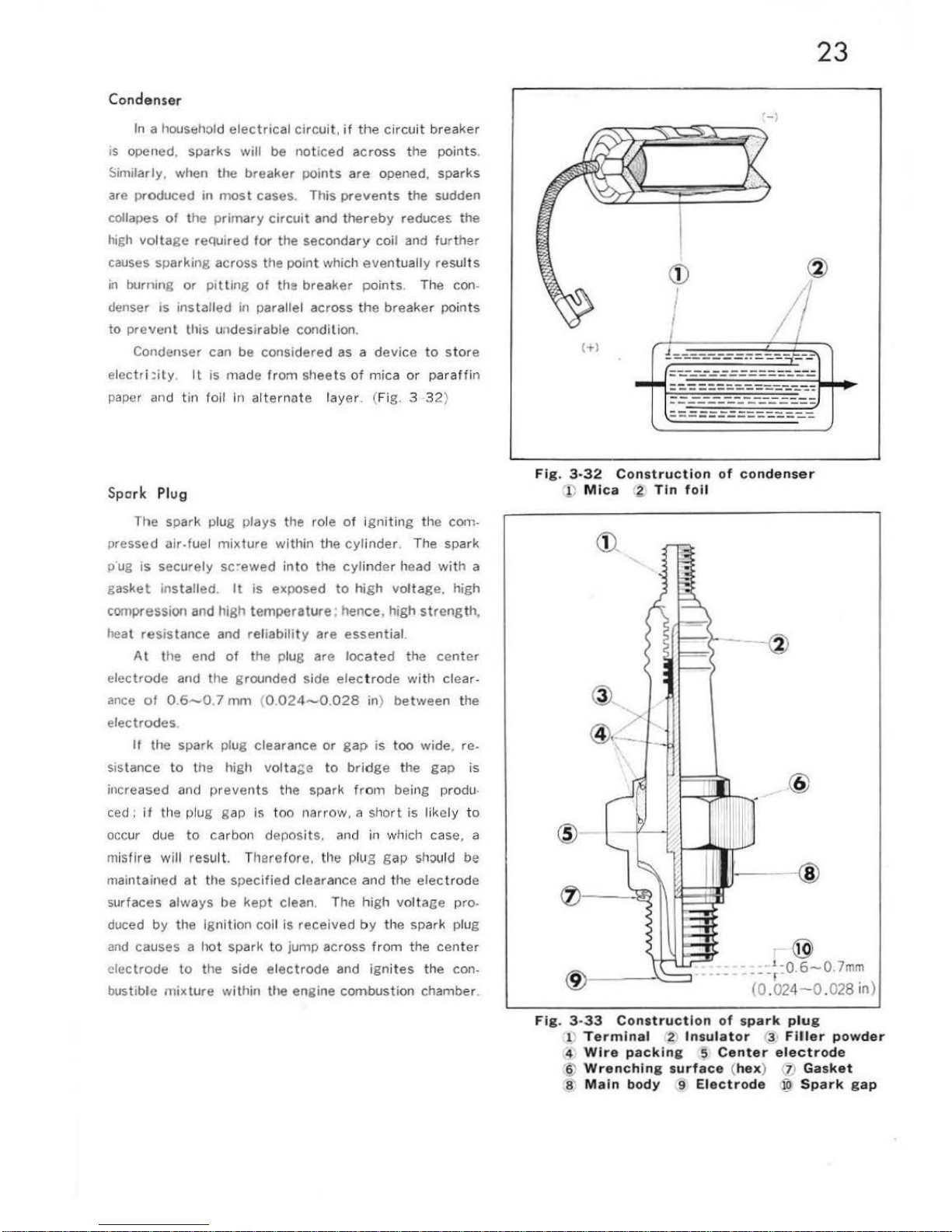
Condenser
In a household
electrical
circuit.
if
the
circuit
breaker
is opened. sparks
will be
noticed
across
the
point
s.
Similarly, when the
breaker
points
are
opened. sparks
are
pr
odu
ced
in
most
cases. This
prevents
the
sudden
collap
es
of
the
primary
circuit
and
thereby
reduce~
the
high
voltage reQui
red
for
the
secondary
coil and fu r
ther
ca
uses sparking across the
point
which
eventually
resul
ts
in
burning
or
pitting
of
the
breaker
points.
The con.
denser
is
installed in
par
allel across the
breaker
points
to pre
vent
this undesi
rable
condition.
Condenser can be considered
as a device
to
store
el
ectri:ily. It
is
made
from
sheets
of
mica
or paraff
in
paper and tin foil
in alternate
layer. (Fig. 3 32)
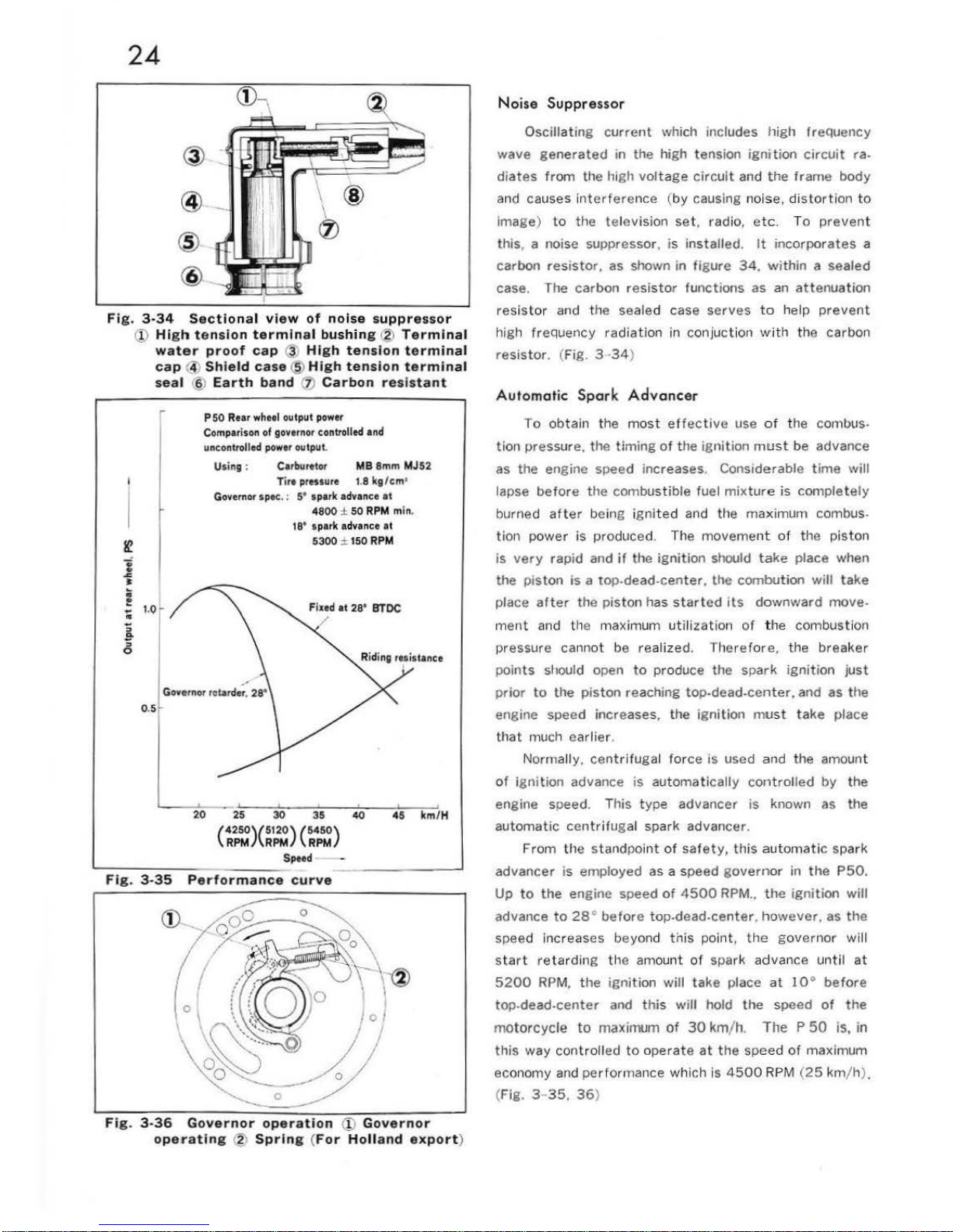
Spark
Plug
The spark plug plays the role of
igniting
the
com-
pressed air-fuel
mixture
with
in the
cylinder
. The spark
p'ug
is
securely
sc·ewed
into t
he
cylinde
r head
with
a
gas
kel
ins
talled
.
It
is exposed
to
high
voltage.
high
compression and high
temperatur
e·
hen
ce,
high strength,
heat resistance
and reliabili
ty
are essential.
At
the end
of
the plug are
located
the
center
elec
trod
e and the grounded side
elec
trode
with
clear
-
ance
of
0.
6-0.7
mm
(0.
024-0.028
in)
between
the
electrodes
.
If
the spark plug clearance
or
gap
is
too
wide.
re.
sistance
to
the high
volta
~e
to
bridge
the
gap
is
increased and pr
events
the
spark from being produ-
ced:
it
the plug gap is too nar
row
, a
short
is
likely
to
occur due
to
ca rbon depos its. and
in
whi
ch
case, a
mi
sfire will resul
t. There
fore. the plug
gap
should be
maintained
at
the
specified
clearance and
the
electrode
surfaces al
ways
be
kept
clean. The
high vol
tage
pro-
duced by the Ignition coil is
received
by the spark plug
an
d causes a
hot
spa rk to jump across from
the
center
electrode
to
the side el
ectrode
and igni
tes
the con-
bustible mixture
within
the engine combustion chamber.
d::::::.-----==---==--=--=-
- --
-=-
==--::_-_-;_----====-
==
Fig. 3·32
Construction
of
condenser
! )
Mica
4
Tin
foil
@
.@
r ®
23
_
-
---~:0.6-0.7m
m
(0 .
024-0
.028 in)
F
ig. 3-33
Construct
ion
of spark plug
1 T
ermin
al
2 I
nsulator
13
Filler
powder
4
Wire
packing
5
Center
electrode
§)
Wrenching
surface (hex
) ] '
Gasket
s'
Main
body
9 Electrode
}9
Spark gap
24
@.
@
@.
Fig. 3-34
Sectional view
of
noise suppre
ssor
.
~
..
..
;;
1!-
"
0
(!) H
igh
tension
termin
al
bushing @
Terminal
water
proof
cap
@ H
igh tension
terminal
cap® Shie
ld
case
@ H
igh
tensi
on
termina
l
sea
l .§)
Earth
band
(j)
Carbon
resistant
P 50
Re
ar wheel
output p
ower
Comparison
of
governor controlled and
uncontrolled
power
output.
Using :
Cerburetor
MB
8mm MJ52
Tire p
rHSUre
1.8
kg
/em•
Governo
r spec. : 5' spark a
dva
nce
at
4800 ± 50
RPM
ml
n.
t8' spark advance at
5300
:::
150
RPM
20
25
30
35
40
45
km/H
(~~)(~:)
(~~)
Speed
---
-
Fig.
3-35
Performance curve
Fi
g. 3-36 Governor operat
ion
(!)
G
overnor
operating
<2)
Spring (For Holl
and
export
)
N
oise
Suppressor
Oscillating
curre
nt which includes high freQuency
wave gene
rated
in
the
high tension
ignition
circuit
ra.
diates
from
the high
voltage
circuit
and the frame
body
and causes i
nterfere
nce (
by
causing noise. distortion
to
i
mag
e) to
the television set, radio,
etc.
To
prevent
this, a noise suppressor.
is
installed.
It incorporates
a
carbon
resistor.
as shown in
figure
34.
within
a seal
ed
case. The carbon resi
stor funct
ions as an
attenuation
resistor
and the sealed case
serves
to
help
prevent
high frequency
radiation
in
conjuct
ion
with
the carbon
resistor. (Fig. 3
·34}
Automatic
Spark
Advancer
To
obtain
the
most
effect
ive
use
of
the
com
bus.
tion pressure. the
timing
of
the ignition
mus
t be advance
as the engine speed in
creas
es. Considerable
time
will
lapse
before
the
combu
stib
le
fuel
mixture is
comple t
ely
burned
after
being
igni
ted and the maximum combus.
tion
power
is produced. The
movement
of
the
piston
is
very
rap
id and
if
the ignition
should take place when
the
piston
is
a top-dead-
center,
the combu
tion will
take
place
after
the piston h
as
started
its
downward
move.
ment
and the maximum util
ization of the combust ion
pressure cannot be real
ized
. Th
erefore,
the bre
aker
points
sltould open
to
produce the spar k
ignition
jus t
prior
to
the
piston
reaching top-dead-center. and as the
engine speed increases. the
ignition must
tak
e place
that
much earlier.
Normally, ce
ntrifugal
force is used and the amount
of
ignition
advance
is
automat ically
controlled
by
the
engine speed. This
type
advancer is known as the
automatic
centr
ifugal spark advancer.
From
the standpoint
of
safety,
this
automati
c spark
advancer
is
employed as a speed
govern
or
in the
P50.
Up
to
the
engine speed
of
4500
RPM
..
the
ignition
will
advance
to 28•
before
top.dead.center.
however.
as
the
speed incr eases
beyo
nd
tnis
point,
the
governor
will
s
tart
reta
rdin g the amount
of
spark advance
until
at
5200 RPM,
the
ignition
will
take
place
at
1 o•
before
top-dead-center and this will hold
the speed
of t he
motorcycle
to maximum
of
30 km/h.
The P 50
is, in
th
is
way
controll
ed
to
operate at
the
speed
of
maximum
economy and pe
rfor
mance which is
4500
RPM
(25 km/h)
.
(Fig.
3-35, 36)
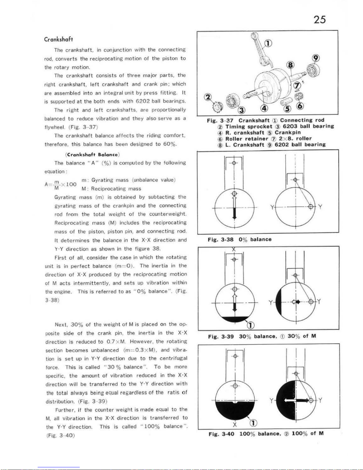
Crankshaft
The
crankshaft.
in conjunction
with
the
connecting
rod,
converts
the
reciprocating
motion
of
the
pist
on
to
the
rotary
motion.
The
crankshaft
consists
of
three
major
part s,
the
right crankshaf t .
left
crankshaft
and crank
pin;
which
are assembled into
an
integral
unit
by
press
fitting.
It
is
supported
at
the
both
ends with
6202
ball bearings.
The
right
and
left
crankshafts,
are
proportional ly
balanced
to
reduce
vibration
and
they
also
serve
as a
flywheel. (
Fig
. 3 37)
The
crankshaft
balance
affects
the
riding
comfort.
therefore,
this
balance has been designed
to
60
%.
(
Crankshaft
Balance
)
The balance
"A"
(%)
is
computed
by
t11
e followi
ng
equati
on:
m m :
Gyrat
ing mass (unbalance value)
A
>;
100
M
M:
Reciprocating
mass
Gyrating
mass (m) is
obtained
by
subtacting
the
gyrating
mass
of
the
crankpin and
the
connecting
rod
from
the
total
weight
of
the
counterweight.
Reciprocating
mass (M) includes the
reciprocating
mass
of
the
piston
, p
iston
pin, and
connect
ing
rod
.
ll
det ermines the balance in the X·X
direction
and
'Y·Y
direction
as shown in
the
figure
38.
First
of
all, consider
the
case in which
the
rotating
unit is in
perfect
balance (m= O
).
The
inertia
in the
direction
of
X·X
produced
by
thP,
reciprocating motion
of
M
acts
intermittently,
and
sets
up
vibra
tion
wit
hin
the
engine. This
is
referred
to
as
"0%
balance". (Fig
.
3
38
)
Next
,
30
%
of
the
weight
of M is
placed on
the op.
posite side
of
the crank pin. the
inertia
in
the
X-X
direction
is
reduced
to
0.7
x M.
However
, the
rotating
section
becomes
unbalanced (rn
=-
0.3
x M
).
and
vibra.
tion
is
set
up in
Y·Y
direction
due
to
the
centrifugal
force.
This
is
called "
30
%
balance". To
be
more
specific,
the
amount
of
vibration
reduced in
the
X-X
direction
will
be
transferred
to
the Y·Y
direction
with
the
total always being
equa
l regardless
of
the
rat
is
of
distribut
ion. (Fig. 3
39)
Further.
if
the
counter
weight
is made equal
to the
M,
all
vibration
in
the
X·X
direction
is
transferred
to
the
Y·Y
direction
. This is called
"100%
balance··.
(Fig. 3 40)
25
Fig
. 3-
37
Crankshaft
(i;)
Connecting rod
2)
Timing
sprocket
@
6203 ball
bearing
!1 R.
crankshaft
~
Crankpin
16 )
Roller
retainer
'z) 2X
8-roll
er
@
L.
Crankshaft
~
6202
ball
bearing
y
Fig. 3-38
0%
balance
y
y
Fig. 3-39
30% balance,
<D
30% of
M
y
Fig
. 3·
40
100% balance, ® 100% of
M
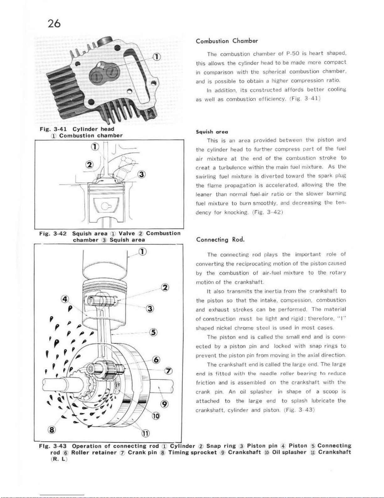
26
Fig.
3-41
Cylinder
head
Q)
Combustion
chamber
Fig.
3-
42
Squish
area
(!)
Valve
1
?.
Combustion
chamber
(3)
Squish
area
- ·®
@
,
·@
,
p
,
- @
'p
,
'
Combustion
Cham
ber
The
combustion chamber
of P-50
is
hea
rt
shaped.
th
is allows
the
cylinder
head
to
be
made
more
com
pact
in compar
ison wi
th
the spherical combustion chamber.
and is
possible
to
obtain a higher
compression
ratio.
In
addition. its
ccnstructed
affords
better
cooling
as well as
combust
io:1
effic
iency. (Fig. 3
41
)
Squish
area
This
is
an
area provided
betwe
un the
piston
and
the
cylinder
head
to further
com
press part
of the fue l
air
mixture
at
the
end
of the combustion stroke
to
cre
at
a turbulence
wit
hin the ma
in
fuel mixture. As the
sw
irli
ng fuel mixture is
divert
ed
toward the
spark plug
the
flame
propagation
is
accelerated. allowing
the the
leaner than normal
fuel-air
ratio
or
the
slow
er
burnmg
fuel
mixtu
re to bu
rn
smoot
l1ly, and
decreasi
ng
the ten-
dency for
knoc king. (Fig. 3 -
42)
Connecting
Rod.
T
he connecting
rod plays
the
important
role
of
conve
rting
the r
eciproca
ting
motion
of the piston
caused
by the com
bust
ion of air-fuel mi
xture to
the
rotary
mo
tion
of
the c
rankshaft
.
It
also
transmits the
iner
tia
from
the cranks
haft
to
tile pi
ston
so
that
the intake.
com
pession.
combust
ion
a
nd
exhaust stro k
es
can
be
performe
d.
The m
ater
ial
of
construction
must
be ligh
t and rigi
d:
therefore, ''I"
shaped
nickel
chr
ome
steel
is
used
in
most
cases.
The
piston
end is ca llt:!d the
sma
ll end and is conn·
ec l ed
by
a piston pin and locked with snap rings
to
prevent the
piston
pin from
moving
in
the
axial
direction.
Th
e crankshaf t end is
called
the
lar
ge
end. The l
arge
e11d
is
fitted
with
the needle roll
er
bearing
tn rP.ciuce
friction
and
is
assembled
on
the
crankshaft
with
the
crank
pin. An
oil splas
her
in sha
pe
of
a scoop is
at
tached
to
the
lar
ge
end
to
splash
lubricate th
e
crankshaf
t, cyl
inder
and piston. (Fi
g.
3
43
)
Fig.
3 -
43
Operation
of
connecting
rod
(l
Cylinder
l£)
Snap
ring
(~;
Piston
pin
~~;
Piston
,5)
Connecting
rod
(6'
Roller
retainer
(J;
Crank
pin
(§
1
Timing
sprocket
~~·
Crankshaft
•10• Oil
splasher
[1;
Crankshaft
(R. L )
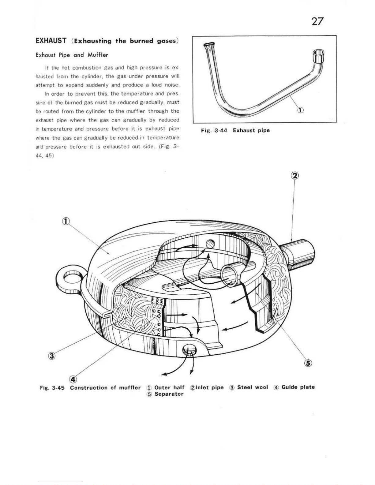
EXHAUST
(
Exhausting
the
burned
gases
)
Exhaust Pipe and
Muffler
If
the
hot
combustion
gas
and high
pressure
is ex -
hausted from the
cylinder,
the
gas
under
pressure will
attempt
to
expand suddenly and produce a loud noise.
In order
to
preven
t t
his
, t
he temper
at u
re
and pres
-
sure
of
the burned
gas
must
be reduced gradually, must
be
routed
from
the
cylinder
to
the
muffler through the
ex
haw;t niPP.
whP.rP. thP.
211~
r.an graduall y
by reduced
in tem
peratu
re
and
pressure
before it is exhaust pipe
wh
ere the
gas
can g raduall y be reduced in t emper
atu
re
an
d pressure before it
is exha
ust
ed out side. (Fig. 3
44
, 4 5)
27
Fig.
3-44
Exhaust
pipe
Fig.
3-45
Construction
of
muffler
j)
Outer
half @Inlet
pipe
@
Steel
wool
'4)
Guide
plate
<Jj)
Separator
 Loading...