

Page 1

owners.honda.com (U.S.)
myhonda.ca (Canada)
31TK8G01 2015 Honda Odyssey Owner’s Guide
00X31-TK8-G010 ©2014 Honda Motor Co., Ltd. — All Rights Reserved Printed in U.S.A.
2015
OWNER’S GUIDE
Page 2

DISCLOSURES
Devices That Emit Radio Waves
The following products and systems on your vehicle emit radio waves when in
operation:
• Audio system • Immobilizer system
• Bluetooth® Audio • Remote transmitter
• Bluetooth® HandsFreeLink® • Smart Entry System
• HomeLink® Universal Transceiver • Tire Pressure Monitoring System
Each of the above complies with the appropriate requirements or the required
standards of the FCC (Federal Communications Commission) and Industry Canada,
described below:
As required by the FCC:
This device complies with Part 15 of the FCC rules. Operation is subject to the
following two conditions: (1) This device may not cause harmful interference, and
(2) this device must accept any interference received, including interference that
may cause undesired operation.
Changes or modications not expressly approved by the party responsible for
compliance could void the user’s authority to operate the equipment.
As required by Industry Canada:
This device complies with Industry Canada Standard RSS-Gen/210/310.
Operation is subject to the following two conditions: (1) this device may not
cause interference, and (2) this device must accept any interference, including
interference that may cause undesired operation of the device.
California Perchlorate Contamination Prevention Act
The airbags, seat belt tensioners, and CR-type batteries in this vehicle may
contain perchlorate materials—special handling may apply. See www.dtsc.
ca.gov/hazardouswaste/perchlorate/ for more information.
California Proposition 65 Warning
WARNING: This product contains or emits chemicals known to the state of
California to cause cancer and birth defects or other reproductive harm.
Event Data Recorders
This vehicle is equipped with an event data recorder (EDR). The main purpose of
an EDR is to record, in certain crash or near crash-like situations, such as an air
bag deployment or hitting a road obstacle, data that will assist in understanding
how a vehicle’s systems performed. The EDR is designed to record data related to
vehicle dynamics and safety systems for a short period of time, typically
30 seconds or less. The EDR in this vehicle is designed to record such data as:
• How various systems in your vehicle were operating;
• Whether or not the driver and passenger safety belts were buckled/fastened;
• How far (if at all) the driver was depressing the accelerator and/or brake
pedal; and,
• How fast the vehicle was traveling.
These data can help provide a better understanding of the circumstances in
which crashes and injuries occur. NOTE: EDR data are recorded by your vehicle
only if a non-trivial crash situation occurs; no data are recorded by the EDR under
normal driving conditions and no personal data (e.g., name, gender, age, and
crash location) are recorded. However, other parties, such as law enforcement,
could combine the EDR data with the type of personally identifying data routinely
acquired during a crash investigation.
To read data recorded by an EDR, special equipment is required, and access to
the vehicle or the EDR is needed. In addition to the vehicle manufacturer, other
parties such as law enforcement that have the special equipment can read the
information if they have access to the vehicle or the EDR.
The data belong to the vehicle owner and may not be accessed by anyone else
except as legally required or with the permission of the vehicle owner.
Service Diagnostic Recorders
This vehicle is equipped with service-related devices that record information
about powertrain performance. The data can be used to verify emissions law
requirements and/or help technicians diagnose and solve service problems. It may
also be combined with data from other sources for research purposes, but
it remains confidential.
Page 3

INTRODUCTION TABLE OF CONTENTS
This Owner’s Guide is intended to help you quickly get acquainted with your 2015
Honda Odyssey. It provides basic information and instructions on technology and
convenience features, as well as emergency procedures and how to get assistance.
This guide is for vehicles sold in the United States and Canada. It covers all Odyssey
models, so you may nd descriptions of features and equipment that are not in your
vehicle. Images throughout this guide are from U.S. vehicles and represent features
and equipment that are available on some, but not all, models.
This guide is not intended to be a substitute for the Owner’s Manual. The Owner
Information CD enclosed in your glove box kit includes the Owner’s Manual,
Navigation Manual, and vehicle and tire warranties in electronic format. This
information can be viewed on a computer (PC or Mac platform) and saved or printed
for your reference. You can also visit owners.honda.com (U.S.) or myhonda.ca
(Canada) to view the complete and most current information.
If you are the rst registered owner of your vehicle, you may request a complimentary
printed copy of the Owner’s Manual, Navigation Manual, or Vehicle Warranty within
the rst six months of vehicle purchase. To request a copy, visit owners.honda.com
and create or log in to your account. In Canada, please request a copy from your
Honda dealer.
American Honda Motor Company strives to be proactive in protecting our
environment and natural resources. By using electronic delivery for a considerable
portion of the information typically found in a vehicle owner’s manual, we are further
reducing our impact on the environment.
Honda Automobile Customer Service
Your authorized Honda dealer should be able to answer any questions you have
about your vehicle. However, if you are dissatised with the information you receive,
you can call Honda Automobile Customer Service (see page 141).
Call (800) 999-1009 (U.S.) or (888) 946-6329 (Canada)
Honda Roadside Assistance
24-hour emergency road service is available to you in the United States and Canada
throughout your 3-year/36,000-mile warranty term. Services include jump starting,
flat tire and lockout assistance, towing, and more (limitations apply).
Call (866) 864-5211 (U.S) or (800) 465-7587 (Canada)
VISUAL INDEX .......................................1
Steering Wheel and Nearby Controls...1
Dashboard and Ceiling Controls ........2
SAFETY INFORMATION ........................3
Important Safety Information ..............3
Seat Belts ...............................................5
Airbags ....................................................9
Child Safety ..........................................15
Safety Label Locations .......................22
Reporting Safety Defects ...................23
INSTRUMENT PANEL .........................24
Malfunction Indicators ......................24
Condition Indicators ...........................26
On/Off Indicators .................................27
Information Display* ..........................28
Multi-Information Display* ...............29
VEHICLE CONTROLS ...........................30
Using the Key or Remote Transmitter ... 30
Smart Entry System* ...........................31
Power Tailgate Operation* ...............32
Door Operation ....................................33
Power Window Operation ................36
Power Moonroof Operation* ...........37
Interior and Exterior Lights ...............38
One-Touch Turn Signal .......................39
Wiper Operation ..................................40
Adjusting the Seats ............................41
Rear Seats ...........................................44
Driving Position Memory System* ... 47
Adjusting the Steering Wheel ..........47
Adjusting the Mirrors .........................48
HomeLink® Garage Opener* .............49
HondaVAC®* ........................................50
Cool Box* .............................................51
Air Conditioning System* .................52
Climate Control System* ..................53
Seat Heaters* ......................................54
Customized Features ..........................55
AUDIO AND CONNECTIVITY .............56
Basic Audio Operation .......................56
Models with one display
Intelligent Multi-Information Display
(i-MID) ...................................................58
FM/AM Radio .......................................59
Compact Disc (CD) ..............................60
iPod® or USB Flash Drive ...................61
Bluetooth® Audio ................................62
Pandora® ..............................................63
Models with two displays
Intelligent Multi-Information Display
(i-MID) ...................................................64
Touchscreen Operation .....................65
FM/AM Radio ......................................66
SiriusXM® Radio .................................67
Compact Disc (CD) .............................68
Hard Disc Drive (HDD) Audio ..........69
iPod® or USB Flash Drive .................70
Bluetooth® Audio ................................71
Pandora® ..............................................72
HondaLink featuring Aha™ ...............73
Rear Entertainment System (RES)* ...74
BLUETOOTH® HANDSFREELINK®.....78
Basic HFL Operation ...........................78
Pairing a Phone ...................................80
Making a Call ......................................81
SMS Text Messaging and E-Mail* ... 83
NAVIGATION* ......................................84
Basic Navigation Operation .............84
*if equipped
Page 4

VISUAL INDEX
Entering a Destination .......................87
Routing ..................................................89
DRIVING ................................................90
Before Driving .....................................90
Maximum Load Limit ..........................91
Towing a Trailer ..................................93
Starting to Drive ..................................95
Braking .................................................96
Vehicle Stability Assist (VSA®), aka
Electronic Stability Control (ESC)
System ...................................................97
Cruise Control ......................................98
LaneWatch™* .....................................99
Forward Collision Warning (FCW)* ... 100
Lane Departure Warning (LDW)* ...101
Blind Spot Information (BSI)* .........102
Parking Sensor System* ..................103
Rearview Camera* ...........................104
Multi-View Rear Camera* ...............105
Refueling ............................................106
HANDLING THE UNEXPECTED .......107
Smart Entry Remote Battery Strength ...107
Jump Starting ....................................107
Shift Lever Does Not Move .............108
Overheating ........................................109
Emergency Engine Stop* .................110
Emergency Towing ...........................110
Tire Pressure Monitoring System
(TPMS) ................................................111
Changing a Flat Tire ..........................111
Fuse Locations ...................................115
MAINTENANCE .................................121
Safety Precautions ...........................121
Maintenance Minder™....................122
Under the Hood ..................................124
Engine Oil ...........................................125
Engine Coolant ..................................127
Checking the Battery ........................128
Window Washer Fluid .....................128
Changing Wiper Blades ...................129
Tire Information .................................131
Tire Labeling ......................................134
DOT Tire Quality Grading .................135
Tire Pressure Monitoring System
(TPMS) - Required Federal
Explanation ........................................136
Testing of Readiness Codes ............138
SPECIFICATIONS ...............................139
CUSTOMER INFORMATION .............140
Frequently Asked Questions/
Troubleshooting ................................140
Contact Us ..........................................141
Honda Roadside Assistance ...........142
Warranty Coverages .........................142
VOICE COMMAND INDEX ................143
INDEX ..................................................150
VISUAL INDEX
Quickly locate items in the vehicle’s interior.
Steering Wheel and Nearby Controls
1513
11 12 10
1
Lights/turn signals/LaneWatch
button* p. 38, p. 39, p. 99
2
SEL/RESET knob p. 28
Brightness control p. 38
3
Wipers/washers p. 40
4
Cruise control buttons p. 98
5
Horn
6
Voice recognition buttons p. 78
7
Audio controls p. 57
8
Instrument panel p. 24
Information display*/Multi-
information display (MID)* p. 28
9
INFO buttons* p. 29
SEL/RESET button* p. 29
1 7
8 2 3
45 96
10
Hood release handle p. 124
11
Power window switches p. 36
14
Door lock switches p. 33
Door mirror controls p. 48
12
Fuel fill door handle p. 106
13
Driving Position Memory System* p. 47
14
ENGINE START/STOP button* p. 95
15
Vehicle Stability Assist (VSA®) OFF
button p. 97
Lane Departure Warning (LDW)
button* p. 101
Power sliding door switch* p. 34
Power tailgate button* p. 32
Parking sensor system button* p. 103
*if equipped*if equipped
| 1
Page 5

SAFETYVISUAL INDEX
Dashboard and Ceiling Controls
6
4
1
Intelligent Multi-Information
Display (i-MID) p. 64
2
Touchscreen* p. 65
3
Hazard warning button
4
Audio/phone/navigation* buttons
p. 64, p. 78, p. 84
5
Climate control system p. 53
6
Seat heater switches* p. 54
8
97
7
USB port p. 56
3 51
2
10
Auxiliary input jack p. 56
8
Moonroof switch* p. 37
Map lights p. 38
HomeLink® buttons* p. 49
9
Cool Box button* p. 51
Center pocket
10
Rear entertainment system* p. 74
SAFETY INFORMATION
Your safety—and the safety of others—is very important and operating this vehicle
safely is an important responsibility. While we strive to help you make informed
decisions about safety, it is not practical or possible to warn you about all the
hazards associated with operating or maintaining your vehicle. Therefore, you must
use your own good judgment.
Important Safety Information
This guide explains many of your vehicle’s safety features and how to use them.
Please read this information carefully. Following the instructions below will also help
to keep you and your passengers safe.
Important Safety Precautions
• Always wear your seat belt.
• Secure all children in the proper restraint system.
• Be aware of airbag hazards.
• Don’t drink and drive.
• Pay appropriate attention to the task of driving safely.
• Control your speed.
• Keep your vehicle in safe condition.
Engaging in cell phone conversation or other activities that keep you from paying
close attention to the road, other vehicles, and pedestrians could lead to a crash.
Remember, situations can change quickly, and only you can decide when it is safe
to divert some attention away from driving.
Safety Messages
When you see the following messages throughout this guide, pay close attention.
You WILL be KILLED or SERIOUSLY HURT if you don’t follow
DANGER
instructions.
You CAN be KILLED or SERIOUSLY HURT if you don’t follow
WARNING
instructions.
You CAN be HURT if you don’t follow instructions.
CAUTION
This information is intended to help you avoid damage to your
NOTICE
vehicle, other property, or the environment.
*if equipped
2 | | 3
Page 6

SAFETYSAFETY
Carbon Monoxide Gas
The engine exhaust from this vehicle contains carbon monoxide, a colorless,
odorless, and highly toxic gas. As long as you properly maintain your vehicle and
follow the instructions set forth below, you will not accumulate dangerous levels
of carbon monoxide gas in the vehicle interior.
Have the exhaust system inspected for leaks whenever:
• The exhaust system is making an unusual noise.
• The exhaust system may have been damaged.
• The vehicle is raised for an oil change.
When you operate a vehicle with the tailgate open, airflow can pull exhaust gas
into the interior and create a hazardous condition. If you must drive with the
tailgate open, open all the windows and set the climate control system as shown
below.
1. Select the fresh air mode.
2. Select the mode.
3. Set the fan speed to high.
4. Set the temperature control to a comfortable setting.
Adjust the climate control system in the same manner if you sit in your parked
vehicle with the engine running.
WARNING
Carbon monoxide gas is toxic. Breathing it can cause unconsciousness and
even kill you.
Avoid any enclosed areas or activities that expose you to carbon monoxide.
An enclosed area such as a garage can quickly ll up with carbon monoxide gas.
Do not run the engine with the garage door closed. Even when the garage door is
open, drive out of the garage immediately after starting the engine.
Seat Belts
A seat belt is your best protection in all types of collisions. Airbags are designed to
supplement seat belts, not replace them. So even though your vehicle is equipped
with airbags, make sure you and your passengers always wear your seat belts and
wear them properly.
Lap/Shoulder Seat Belts
All seven or eight seating positions are equipped with lap/shoulder seat belts with
emergency locking retractors. In normal driving, the retractor lets you move freely
while keeping some tension on the belt. During a collision or sudden stop, the
retractor locks to restrain your body. The second- and third-row passenger’s seat
belts also have a lockable retractor for use with child seats.
The front seats are equipped with automatic seat belt tensioners to enhance
safety. The tensioners automatically tighten the front seat belts during a moderate
to severe frontal collision, sometimes even if the collision is not severe enough to
inate the front airbags.
Proper Use of Seat Belts
Follow these guidelines for proper use:
• All occupants should sit upright, well back in the seat, and remain in that
position for the duration of the trip. Slouching and leaning reduces the
effectiveness of the belt and can increase the chance of serious injury in a
crash.
• Never place the shoulder part of a lap/shoulder seat belt under your arm or
behind your back. This could cause very serious injuries in a crash.
• Two people should never use the same seat belt. If they do, they could be very
seriously injured in a crash.
• Do not put any accessories on the seat belts. Devices intended to improve
comfort or reposition the shoulder part of a seat belt can reduce the protective
capability and increase the chance of serious injury in a crash.
• Regularly check the condition of your seat belts. Check for frays, cuts, burns,
and wear, and that the latches work smoothly and the belts retract easily.
• No one should sit in a seat with an inoperative seat belt or one that does not
appear to be working correctly. Using a seat belt that is not working properly
may not protect the occupant in a crash. Have a dealer check the belt as soon
as possible.
WARNING
Not wearing a seat belt properly increases the chance of a serious injury or
death in a crash, even though your vehicle has airbags.
Be sure you and your passengers always wear seat belts and wear them
properly.
4 | | 5
Page 7

SAFETYSAFETY
Seat Belt Inspection
Regularly check the condition of your seat belts as follows:
• Pull each belt out fully, and look for frays, cuts, burns, and wear.
• Check that the latches work smoothly and the belts retract easily. If a belt does
not retract easily, cleaning the belt may correct the problem. Use only mild soap
and warm water. Do not use bleach or cleaning solvents. Make sure the belt is
completely dry before allowing it to retract.
Any belt that is not in good condition or working properly will not provide proper
protection and should be replaced as soon as possible.
A belt that has been worn during a crash may not provide the same level of
protection in a subsequent crash. Have your seat belts inspected by a dealer after
any collision.
WARNING
Not checking or maintaining seat belts can result in serious injury or death if
the seat belts do not work properly when needed.
Check your seat belts regularly and have any problem corrected as soon as
possible.
Fastening a Seat Belt
Adjust your seat to the proper position (see page 41), and then follow the below
steps.
1. Pull the seat belt out slowly.
2. Insert the latch plate into the buckle, then tug
Pull out
slowly.
on the belt to make sure the buckle is secure.
Make sure that the belt is not twisted or caught
on anything.
3. Position the lap part of the belt as low as possible
across your hips, then pull up on the shoulder
part of the belt so the lap part ts snugly. This lets
Latch
plate
your strong pelvic bones take the force of a crash
and reduces the chance of internal injuries.
4. If necessary, pull up on the belt again to remove
Buckle
any slack, then make sure that the belt rests
across the center of your chest and over your
shoulder. This spreads the forces of a crash over
the strongest bones in your upper body.
To release the belt, push the red PRESS button
Lap belt
as low as
possible.
then guide the belt by hand until it has retracted
completely.
WARNING
Improperly positioning the seat belts can cause serious injury or death in a
crash.
Make sure all seat belts are properly positioned before driving.
Adjusting the Shoulder Anchor
The front seats have adjustable shoulder anchors to accommodate taller and
shorter occupants.
1. Move the anchor up and down while holding the
release button.
Push
2. Position the anchor so that the belt rests across
the center of your chest and over your shoulder.
6 | | 7
Page 8

SAFETYSAFETY
Seat Belt with Detachable Anchor
The seat belt for the second-row and third-row center seat is located in the
ceiling.
1. Pull out the seat belt’s small latch plate and
the latch plate from each holding slot in the
ceiling.
2. Line up the triangle marks on the small latch plate
and anchor buckle. Make sure the seat belt is not
twisted. Attach the belt to the anchor buckle.
3. Insert the latch plate into the buckle. Properly
fasten the seat belt the same way you fasten
the lap/shoulder seat belt.
Buckle
To unlatch the detachable anchor, insert a key
into the slot on the side of the anchor buckle.
For the second-row center seat, pivot the
anchor buckle forward before unlatching the
anchor.
WARNING
Using the seat belt with the detachable anchor unlatched increases the
chance of serious injury or death in a crash.
Before using the seat belt, make sure the detachable anchor is correctly
latched.
Latch
plate
Airbags
Your vehicle is equipped with three types of airbags: front airbags, side airbags, and
side curtain airbags.
Front Airbags (SRS)
The front SRS airbags inate in a moderate-to-severe frontal collision to help
protect the head and chest of the driver and/or front passenger. They are housed
in the center of the steering wheel for the driver, and in the dashboard for the front
passenger. Both airbags are marked SRS AIRBAG.
SRS (Supplemental Restraint System) indicates that the airbags are designed to
supplement seat belts, not replace them. Seat belts are the occupant’s primary
restraint system.
Advanced Airbags
Your front airbags have advanced features to help reduce the likelihood of airbag-
related injuries to smaller occupants.
The driver’s advanced front airbag system includes
a seat position sensor. If the seat is too far forward,
the airbag inates with less force, regardless of the
severity of the impact.
If there is a problem with the driver’s seat position
sensor, the SRS indicator will come on and the
airbag will inate with full (normal) force, regardless
of the driver’s seating position.
The passenger’s advanced front airbag system
has weight sensors. Although Honda recommends
against carrying an infant or small child in front, if
the sensors detect the weight of a child (up to 65 lbs
or 29 kg), the system will automatically turn off the
Passenger’s
seat
weight
sensors
passenger’s front airbag.
For both advanced front airbags to work properly:
• Do not spill any liquid on or under the seats.
• Do not put any object under the passenger’s seat.
• Make sure any objects are positioned properly on the oor. Improperly
positioned objects can interfere with the advanced airbag sensors.
• All occupants should sit upright and wear their seat belts properly.
• Do not place any cover over any part of the passenger side dashboard.
Driver’s
seat
position
sensor
8 | | 9
Page 9

SAFETYSAFETY
*
Side Airbags
The side airbags help protect the upper torso and pelvis of the driver or a front
passenger during a moderate-to-severe side impact. They are housed in the
outside edge of the driver’s and front passenger’s seat-backs. Both are marked
SIDE AIRBAG.
Side Curtain Airbags
Side curtain airbags help protect the head and torso of the driver and passengers
in outer seating positions during a moderate-to-severe side impact. The side
curtain airbags equipped in this vehicle are also designed to help reduce the
likelihood of partial and complete ejection of vehicle occupants through side
windows in crashes, particularly rollover crashes.
The side curtain airbags are located in the ceiling
above the side windows on both sides of the
vehicle.
The side curtain airbags are designed to deploy
in a rollover or moderate-to-severe side impact.
If the SRS control unit senses that your vehicle is
Side curtain airbag storage
about to roll over, it immediately deploys both side
curtain airbags and activates both front seat belt
tensioners. If the impact is on the passenger’s side,
the passenger’s side curtain airbag will inate even
if there are no occupants on that side of the vehicle.
Deployed side curtain airbag
To get the best protection from the side curtain airbags, occupants should wear
their seat belts properly and sit upright and well back in their seats.
Do not attach any objects to the side windows or roof pillars, as they can interfere
with the proper operation of the side curtain airbags.
When side curtain airbags deploy in a frontal collision
One or both side curtain airbags may inate in a moderate-to-severe angled
frontal collision. In this case, the side curtain airbags will deploy slightly after the
front airbags.
Important Facts About Your Airbags
Always wear your seat belt properly, and sit upright and as far back from the
steering wheel as possible while allowing full control of the vehicle. A front
passenger should move their seat as far back from the dashboard as possible.
Do not place hard or sharp objects between yourself and a front airbag. Carrying
hard or sharp objects on your lap, or driving with a pipe or other sharp object in
your mouth, can result in injuries if your front airbag inates.
Do not attach or place objects on the front airbag covers. Objects on the covers
marked SRS AIRBAG could interfere with the proper operation of the airbags or be
propelled inside the vehicle and hurt someone if the airbags inate.
Do not attach accessories on or near the side airbags. They can interfere with the
proper operation of the airbags, or hurt someone if an airbag inates.
Do not attach any objects to the side windows or roof pillars. They can interfere
with the proper operation of the side curtain airbags.
Do not cover or replace the front seat-back covers. This can prevent your side
airbags from properly deploying during a side impact.
WARNING
An open glove box can cause serious injury to your passenger in a crash,
even if the passenger is wearing the seat belt.
Always keep the glove box closed while driving.
Airbag System Indicators
If a problem occurs in the airbag system, the SRS indicator comes on and a
message appears on the multi-information display*.
SRS (Supplemental Restraint System) Indicator
If the indicator comes on at any other time besides
vehicle start-up, or does not come on at all, have the
system checked by a dealer as soon as possible. If
you don’t, your airbags and seat belt tensioners may
not work properly when they are needed.
WARNING
Ignoring the SRS indicator can result in serious injury or death if the airbag
systems or tensioners do not work properly.
Have your vehicle checked by a dealer as soon as possible if the SRS
indicator alerts you to a possible problem.
10 | | 11
*if equipped
Page 10

SAFETYSAFETY
U.S.
Canada
6
789
8
8
8
8
12
11
10
Passenger Airbag Off Indicator
Airbag System Components
The indicator comes on to alert you that the front
passenger’s front airbag has been turned off. This
occurs when the front passenger’s weight sensors
detect 65 lbs (29 kg) or less, the weight of an infant
or small child, on the seat.
Infants and small children should always ride properly restrained in a back seat.
Objects placed on the seat can also cause the indicator to come on.
If the front passenger‘s seat is empty, the passenger’s front airbag will not deploy
and the indicator will not come on.
If the indicator comes on with no occupant or objects in the front passenger’s
seat, something may be interfering with the weight sensors, such as:
• An object hanging on the seat or in the seat-back pocket.
• A child seat or other object pressing against the rear of the seat-back.
• A rear passenger pushing or pulling on the back of the front passenger’s seat.
1
• The front seat or seat-back is forced against an object on the seat or oor
behind it.
• An object placed under the front passenger’s seat.
If none of these conditions exist, have your vehicle checked by a dealer as soon
as possible.
The passenger airbag off indicator may go on and off repeatedly if the total weight
on the seat is near the airbag cutoff threshold.
Two SRS (Supplemental Restraint
System) front airbags. The driver’s
airbag is stored in the center
of the steering wheel; the front
passenger’s airbag is stored in the
dashboard. Both are marked SRS
AIRBAG.
2
Two side airbags, one for the driver
and one for the front passenger.
The airbags are stored in the outer
edges of the seat-backs. Both are
marked SIDE AIRBAG.
3
Two side curtain airbags, one
for each side of the vehicle. The
airbags are stored in the ceiling,
above the side windows. The front
and rear pillars are marked SIDE
CURTAIN AIRBAG.
4
An electronic control unit that
continually monitors and can
record information about the
sensors, the airbag activators, the
seat belt tensioners, and driver and
front passenger seat belt use when
the vehicle is on.
12 | | 13
5
Automatic front seat belt tensioners.
The driver’s and front passenger’s
seat belts incorporate sensors that
detect whether or not they are
fastened.
6
A driver’s seat position sensor. If the
seat is too far forward, the airbag
will inflate with less force.
7
Weight sensors in the front
passenger’s seat. The front
passenger’s airbag will be turned off
if the weight on the seat is 65 lbs (29
kg) or less (the weight of an infant or
small child).
8
Impact sensors that can detect a
moderate-to-severe front or side
impact.
9
An indicator on the dashboard that
alerts you that the front passenger’s
front airbag has been turned off.
10
An indicator on the instrument panel
that alerts you to a possible problem
with the airbag system or seat belt
tensioners.
11
Safing sensor
12
A rollover sensor that detects
whether the vehicle is about to roll
over.
Page 11

SAFETYSAFETY
Airbag Care
You do not need to, and should not, perform any maintenance on or replace any
airbag system components yourself. However, you should have your vehicle
inspected by a dealer in the following situations:
When the airbags have deployed
If an airbag has inated, the control unit and other related parts must be replaced.
Similarly, once an automatic seat belt tensioner has been activated, it must be
replaced.
When the vehicle has been in a moderate-to-severe collision
Even if the airbags did not inate, have your dealer inspect the following: the
driver’s seat position sensor, weight sensors in the passenger’s seat, front seat
belt tensioners, and each seat belt that was worn during the crash.
Do not remove or modify a front seat without first consulting a dealer
This would likely disable the driver’s seat position sensor or the weight sensors
in the passenger’s seat. If it is necessary to remove or modify a front seat to
accommodate a person with disabilities, contact a Honda dealer. For U.S.
vehicles, call Honda Automobile Customer Service at (800) 999-1009. For Canadian
vehicles, call Honda Canada Customer Relations at (888) 946-6329.
Child Safety
Each year, many children are injured or killed in vehicle crashes because they are
either unrestrained or not properly restrained. In fact, vehicle collisions are the
number one cause of death of children ages 12 and under.
The National Highway Traffic Safety Administration and Transport Canada
recommend that all children ages 12 and under be properly restrained in a rear seat.
Some states or provinces/territories have laws restricting where children may ride.
To reduce the number of child deaths and injuries, every state, Canadian province
and territory requires that infants and children be properly restrained when they ride
in a vehicle.
Protecting Child Passengers
• An inating front or side airbag can injure or kill a child sitting in the front seat.
• A child in the front seat is more likely to interfere with the driver’s ability to
safely control the vehicle.
• Statistics show that children of all sizes and ages are safer when they are
properly restrained in a rear seat.
• Any child who is too small to wear a seat belt correctly must be restrained in an
approved child seat that is properly secured to the vehicle using either the lap
belt portion of the lap/shoulder belt or the lower anchors of the LATCH system.
• Never hold a child on your lap because it is impossible to protect them in the
event of a collision.
• Never put a seat belt over yourself and a child. During a crash, the belt would
likely press deep into the child and cause serious or fatal injuries.
• Never let two children use the same seat belt. Both children could be very
seriously injured in a crash.
• Do not allow children to operate the doors, windows, or seat adjustments.
• Do not leave children in the vehicle unattended, especially in hot weather when
the inside of the vehicle can get hot enough to kill them. They could also activate
vehicle controls, causing it to move unexpectedly.
WARNING
Children who are unrestrained or improperly restrained can be seriously
injured or killed in a crash.
Any child too small for a seat belt should be properly restrained in a child
seat. A larger child should be properly restrained with a seat belt, using a
booster seat if necessary.
14 | | 15
Page 12

SAFETYSAFETY
WARNING
Allowing a child to play with a seat belt or wrap one around their neck can
result in serious injury or death.
Instruct children not to play with any seat belt and make sure any unused seat
belt a child can reach is buckled, fully retracted, and locked.
Protecting Infants
An infant must be properly restrained in a rear-facing, reclining child seat until the
infant reaches the seat maker’s weight or height limit for the seat, and the infant
is at least one year old. Many experts recommend use of a rear-facing seat for
a child up to two years old if the child’s height and weight are appropriate for a
rear-facing seat.
Child seats must be placed and secured in a rear
seating position. Rear-facing child seats should
never be installed in a forward-facing position.
When properly installed, a rear-facing child seat may prevent the driver or a front
passenger from moving their seat all the way back, or from locking their seat-back
in the desired position. If this occurs, we recommend that you install the child
seat directly behind the front passenger’s seat, move the seat as far forward as
needed, and leave it unoccupied. Or, you may wish to get a smaller rear-facing
child seat.
WARNING
Placing a rear-facing child seat in the front seat can result in serious injury or
death during a crash.
Always place a rear-facing child seat in the rear seat, not the front.
Protecting Smaller Children
If a child is at least one year old and within the weight range indicated by the child
seat manufacturer, the child should be properly restrained in a rmly secured
forward-facing child seat.
We strongly recommend placing a forward-facing
child seat in a rear seating position.
Placing a forward-facing child seat in the front seat
can be hazardous, even with advanced front airbags
that automatically turn the passenger’s front airbag
off. A rear seat is the safest place for a child.
WARNING
Placing a forward-facing child seat in the front seat can result in serious
injury or death if the front airbag inates.
If you must place a forward-facing child seat in front, move the vehicle seat
as far back as possible, and properly restrain the child.
Selecting a Child Seat
Most child seats are LATCH-compatible (Lower Anchors and Tethers for CHildren).
Some have a rigid-type connector, while others have a exible-type connector.
Both are equally easy to use. Some existing and previously owned child seats can
only be installed using the seat belt. Whichever type you choose, follow the child
seat manufacturer’s use and care instructions as well as the instructions in this
manual. Proper installation is key to maximizing your child’s safety.
In seating positions and vehicles not equipped with LATCH, a LATCH-compatible
child seat can be installed using the seat belt and a top tether for added security.
This is because all child seats are required to be designed so that they can be
secured with a lap belt or the lap part of a lap/shoulder belt. In addition, the
child seat manufacturer may advise that a seat belt be used to attach a LATCHcompatible seat once a child reaches a specied weight. Please read the child
seat owner’s manual for proper installation instructions.
Important considerations when selecting a child seat
Make sure the child seat meets the following three requirements:
• The child seat is the correct type and size for the child.
• The child seat is the correct type for the seating position.
• The child seat is compliant with Federal Motor Vehicle Safety Standard 213 or
Canadian Motor Vehicle Safety Standard 213.
16 | | 17
Page 13

SAFETYSAFETY
Installing a LATCH-Compatible Child Seat
A LATCH-compatible child seat can be installed in each of the second- and third-
row seats. A child seat is attached to the lower anchors with either the rigid or
exible type of connectors.
1. Locate the lower anchors under the marks.
Second-row seat
2. Place the child seat on the vehicle seat, then
attach the child seat to the lower anchors
according to the instructions that came with the
child seat. Make sure that the lower anchors
are not obstructed by the seat belt or any other
Third-row seat
Marks
object.
To install a child seat in the second-row center
seat, remove the covers on each lower end of the
seat-back by pulling on the handles.
Lower anchors
Cover
Marks
3. Raise the head restraint to its uppermost position,
then route the tether strap between the head
restraint legs, and secure the tether strap hook
Handle
onto the anchor.
Flexible type
4. Tighten the tether strap according to the seat
maker’s instructions.
Second-row outer position
5. Make sure the child seat is rmly secured by
rocking it forward and back and side to side; little
Rigid type
Anchor
Tether
strap
hook
movement should be felt.
Installing a Child Seat with a Lap/Shoulder Seat Belt
1. Place the child seat on the vehicle seat.
2. Route the seat belt through the child seat
according to the seat maker’s instructions, and
insert the latch plate into the buckle. Insert the
latch plate fully until it clicks.
3. Slowly pull the shoulder part of the belt all the
way out until it stops. This activates the lockable
retractor.
4. Let the seat belt completely wind up into the
retractor, then try to pull it out to make sure the
retractor is locked. If you are able to pull the
shoulder belt out, the lockable retractor is not
activated. Pull the seat belt all the way out, and
repeat steps 3 – 4.
5. Grab the shoulder part of the seat belt near the
buckle, and pull up to remove any slack from
the lap part of the belt. When doing this, place
your weight on the child seat and push it into the
vehicle seat.
6. Make sure the child seat is rmly secured by
rocking it forward and back and side to side; little
movement should be felt.
7. Make sure any unused seat belt that a child
can reach is buckled, the lockable retractor
is activated, and the belt is fully retracted and
locked.
To deactivate a lockable retractor, release the buckle and allow the seat belt to
wind up all the way.
6. Make sure any unused seat belt that a child
can reach is buckled, the lockable retractor
is activated, and the belt is fully retracted and
Second row center seat
Tether
strap
hook
locked.
Anchor
18 | | 19
Page 14

SAFETYSAFETY
Adding Security with a Tether
A tether anchorage point is provided behind each rear seating position.
Regardless of whether it is installed with LATCH or a seat belt, a child seat that
comes with a tether should use the tether for additional security.
1. Locate the appropriate tether anchorage point
and lift the cover.
2. Raise the head restraint to its uppermost position,
Second-row seat
Tether anchorage points
Third-row seat
Tether anchorage points
Second-row outer position
then route the tether strap through the head
restraint legs. Make sure the strap is not twisted.
3. Secure the tether strap hook onto the anchor.
Second-row center seat
Tether
strap
hook
Tether
strap
hook
Anchor
Protecting Larger Children
When a child is too big for a child seat, secure the child in a rear seat using the
lap/shoulder seat belt.
Have the child sit upright and all the way back, then ensure the following:
• The child’s knees bend comfortably over the edge
of the seat.
• The shoulder belt crosses between the child’s
neck and arm.
• The lap part of the seat belt is as low as possible,
touching the child’s thighs.
• The child can stay seated for the whole trip.
If a lap/shoulder belt cannot be used properly, position the child in a booster seat
in a rear seating position. For the child’s safety, check that the child meets the
booster seat manufacturer’s recommendations.
Some U.S. states and Canadian provinces/territories require children to use a
booster seat until they reach a given age or weight (e.g., 6 years or 60 lbs). Be sure
to check current laws in the state or province/territory where you intend to drive.
WARNING
Allowing a child age 12 or under to sit in the front can result in injury or death
if the passenger’s front airbag inates.
If a larger child must ride in front, move the vehicle seat as far to the rear as
possible, then have the child sit up properly and wear the seat belt properly,
using a booster seat if needed.
4. Tighten the tether strap according to the seat
maker’s instructions.
20 | | 21
Anchor
Third-row seat
Tether
strap
hook
Anchor
Anchor
Page 15

SAFETYSAFETY
Safety Label Locations
Safety labels are in the locations shown. They warn you of potential hazards that
can cause serious injury or death. Read these labels carefully.
Sun visor
U.S. models Canadian models
Dashboard
U.S. models only
Radiator cap
Doorjambs
U.S. models
Canadian models
Reporting Safety Defects
In the U.S.
If you believe that your vehicle has a defect which could cause a crash or could
cause injury or death, you should immediately inform the National Highway Traffic
Safety Administration (NHTSA) in addition to notifying American Honda Motor Co.,
Inc.
If NHTSA receives similar complaints, it may open an investigation, and if it nds
that a safety defect exists in a group of vehicles, it may order a recall and remedy
campaign. However, NHTSA cannot become involved in individual problems
between you, your dealer, or American Honda Motor Co., Inc.
To contact NHTSA, you may call the Vehicle Safety Hotline toll-free at 1-888-327-
4236 (TTY: 1-800-424-9153); go to http://www.safercar.gov; or write to: Administrator,
NHTSA, 1200 New Jersey Avenue, SE., Washington, DC 20590. You can also obtain
other information about motor vehicle safety from http://www.safercar.gov.
In Canada
If you believe that your vehicle has a defect which could cause a crash or could
cause injury or death, you should immediately inform Honda Canada, Inc., and you
may also inform Transport Canada.
If Transport Canada receives similar complaints, it may open an investigation, and if
it finds that a safety defect exists in a group of vehicles, it may lead to a recall and
remedy campaign. However, Transport Canada cannot become involved in individual
problems between you, your dealer, or Honda Canada, Inc.
To contact Transport Canada’s Defect Investigations and Recalls Division, you may
call 1-800-333-0510. For more information on reporting safety defects or about motor
vehicle safety, go to http://www.tc.gc.ca/roadsafety.
22 | | 23
Page 16

INSTRUMENT PANELINSTRUMENT PANEL
Canada
INSTRUMENT PANEL
Learn about the indicators, gauges, and displays related to driving the vehicle.
Indicators briey appear with each engine start and then go out. Red and amber
indicators are most critical. Blue and green indicators are used for general
information.
Malfunction Indicators
These are the most critical indicators. If they come on and stay lit while driving or at
any other time, there may be a problem. See your dealer if necessary.
Brake system
U.S.
• Brake uid is low.
• The brake system has a problem.
Canada
Press the brake pedal lightly to check pedal pressure. If normal, check
the brake uid level when you stop. If abnormal, take immediate action. If
necessary, downshift the transmission to slow the vehicle using engine
braking. Have your vehicle repaired immediately.
Malfunction indicator lamp (check engine light)
• The emissions control system may have a problem, or the fuel cap is loose
or missing.
• (Blinks) A misre in the engine’s cylinders is detected. Stop in a safe place,
and wait for the engine to cool down.
Anti-lock Brake System (ABS)
There is a problem with the anti-lock brake system. Your vehicle still has
normal braking ability, but no anti-lock function.
Tire Pressure Monitoring System (TPMS)*
There is a problem with the tire pressure monitoring system, or the vehicle is
fitted with the compact spare tire.
Power tailgate*
U.S.
There is a problem with the power tailgate system. You can still open the
Canada
power tailgate manually.
Power sliding doors*
U.S.
There is a problem with the power sliding door system. You can still open the
power sliding doors manually.
Canada
Daytime Running Lights (DRL)*
There is a problem with the DRL system.
Vehicle Stability Assist (VSA®) system
There is a problem with the VSA system.
Brake system
SYSTEM
U.S.
There is a problem with the brake override system.
Low oil pressure
Engine oil pressure is low. Stop in a safe place. Open the hood. Check the oil
level, and add oil if necessary (see page 126). If the indicator does not turn
off, have your vehicle repaired immediately.
Charging system
Forward Collision Warning (FCW) system*
There is a problem with the FCW system.
Lane Departure Warning (LDW) system*
There is a problem with the LDW system.
The battery is not charging. Turn off all electrical items, but do not turn off
the vehicle to prevent further battery discharge. Have your vehicle repaired
immediately.
Supplemental Restraint System (SRS)
There is a problem with one of the airbag systems or seat belt tensioners.
Smart Entry system*
Starter system*
U.S.
There is a problem with the starter system.
Canada
Blind spot information (BSI) system*
There is a problem with the BSI system.
There is a problem with the smart entry system.
*if equipped
24 | | 25
*if equipped
Page 17

Condition Indicators
These indicators may require you to perform an action.
INSTRUMENT PANELINSTRUMENT PANEL
Forward Collision Warning (FCW) system*
(Blinks) Take appropriate action to avoid a collision.
Lane Departure Warning (LDW) system*
(Blinks) Take appropriate action to keep the vehicle within the lane.
Maintenance Minder™*
Scheduled maintenance for your vehicle is due.
Immobilizer
Your key or remote transmitter cannot be recognized by the vehicle. If the
indicator blinks, you may not be able to start the engine. Turn the vehicle off,
and then on again. If it continues to blink, there may be a problem with the
system. See your dealer.
Parking brake
U.S.
Release the parking brake before driving. You will hear a beep if you drive
with it not fully released.
Canada
Seat belt reminder
Make sure seat belts are fastened for you and all passengers. The indicator
blinks and beeps sound continuously if you or your front passenger has not
fastened your seat belts when you begin driving. If the indicator remains on
after seat belts are fastened, see your dealer.
Low fuel
Refuel as soon as possible. If the indicator blinks, there is a problem with the
fuel gauge. See your dealer.
Low tire pressure
Stop in a safe place, check tire pressures, and inflate tire(s) if necessary.
The indicator also appears if your vehicle is fitted with the compact spare
tire. Have your regular tire repaired or replaced as soon as possible.
System message*
When a condition or malfunction indicator comes on, a message also
appears on the multi-information display. Check the display for more
information.
Vehicle Stability Assist (VSA
®
) system
(Blinks) VSA is active.
On/Off Indicators
These indicators remind you when an item is on or off.
VSA off
FCW* off
BSI* off
CRUISE MAIN on
CRUISE CONTROL on
Turn signals/hazards on
Fog lights* on
Fuel-efficient driving
High beams on
Exterior lights on
*if equipped
26 | | 27
*if equipped
Page 18

INSTRUMENT PANELINSTRUMENT PANEL
Information Display*
Consists of several displays that provide you with useful information.
When you start the
engine, the display shows
your last active selection
from the previous drive
cycle.
Press the select/reset
knob to change the
display.
Information Displays
Odometer, Outside
temperature*
Trip meter A,
Engine oil life
Average fuel economy
Trip meter B
Range, Instant
fuel economy
Multi-Information Display*
Consists of several displays that provide you with useful information.
Main display
Lower display
Info buttons: Press to
change main displays.
SEL/RESET button: Press
to change lower displays.
Main Displays
Odometer, Outside
temperature
Customize Settings
Average fuel economy/
Instant fuel economy
Average speed
Range
Elapsed time
Lower Displays
Odometer,
Outside temperature
*if equipped
28 | | 29
Trip A,
Outside temperature
Trip B,
Outside temperature
Engine oil life
*if equipped
Page 19

VEHICLE CONTROLSVEHICLE CONTROLS
VEHICLE CONTROLS
Learn about the various controls necessary for operating and driving the vehicle.
Using the Key or Remote Transmitter
Lock or unlock the doors and tailgate.
Unlock button: Press once
to unlock the driver’s door.
Press again to unlock all
doors and the tailgate.
Unlock button: Press once
to unlock the driver’s door.
Press again to unlock all
doors and the tailgate.
Power sliding door
buttons*: Press to open
the sliding door. Press
again to stop the door
during operation. Press
again to close the door.
Power tailgate button*:
Press and hold to unlock
and open the power
tailgate. Press again to
close it.
Lock button: Press to lock the
doors and tailgate. Press again
for audible verication.
Panic button: Press and
hold to sound the alarm for
30 seconds. Press again to
cancel.
Lock button: Press to lock the
doors and tailgate. Press again
for audible verication.
Panic button: Press to sound
the alarm for 30 seconds.
Press again to cancel.
Built-in key: Slide the release
knob on the back of the
transmitter and pull out the
built-in key.
Release knob
NOTICE
Leaving the key or remote transmitter in the vehicle can result in theft or
accidental movement of the vehicle. Always take it with you whenever you leave
the vehicle unattended.
Smart Entry System*
When you carry the remote transmitter (for example, in a pocket or purse) and it
is outside the vehicle and within range (about 32 inches or 80 cm), you can lock or
unlock the doors and tailgate without handling the transmitter.
Unlocking/Locking the Doors
To unlock: Grab the driver’s door handle when the
vehicle is off to unlock the driver’s door. Grab the
front passenger’s or rear door handle to unlock all
doors and the tailgate.
To lock: Press the door lock button on either front
door handle when the vehicle is off. If the remote
transmitter is inside the vehicle, the doors will not
lock.
Unlocking/Locking the Tailgate
To unlock: Press and hold the tailgate release
button under the tailgate handle to unlock the
tailgate and all doors. The vehicle can be on or off.
If there is not enough clearance for the tailgate to
fully open, press and hold the tailgate release button
until you hear two beeps. The tailgate unlatches,
and you can open it manually.
To lock: Press the tailgate lock button to lock the
tailgate and all doors. If the remote transmitter is
inside the vehicle, the tailgate and doors will not
lock.
Lock button
Door lock
button
Tailgate
outer
handle
Built-in key
*if equipped
30 | | 31
*if equipped
Page 20

VEHICLE CONTROLSVEHICLE CONTROLS
Power Tailgate Operation*
Use these methods to operate the power tailgate.
Power Tailgate Button
The vehicle must be in Park (P) with all doors
unlocked.
Press and hold the power tailgate button on the
dashboard to open the tailgate. Press it again at any
time to close it.
Power Tailgate Close Button
Press the power tailgate close button to
automatically close the tailgate. Press it again at
any time to reverse the tailgate direction.
Power tailgate
close button
WARNING
Closing the power tailgate while anyone is in the path of the tailgate can
cause serious injury.
Make sure everyone is clear before closing the tailgate.
NOTICE
Do not push or pull on the power tailgate when it is being automatically opened
or closed. Forcibly opening or closing the power tailgate while in operation can
deform the tailgate frame.
Power
tailgate
button
Door Operation
Use several methods to lock or unlock the doors.
Using the Lock Tab
To unlock: When you unlock either front door
using the lock tab, the specic door (driver’s or
passenger’s) unlocks.
To lock: When you lock the door using the lock tab
on the driver’s door, all the other doors and tailgate
lock at the same time. When you lock the door using
the lock tab on the front passenger’s door, only that
door locks.
Using the Master Door Lock Switch
To unlock: Press the unlock side of the switch to
unlock all doors and the tailgate.
To lock: Press the lock side of the switch to lock all
doors and the tailgate.
The front passenger’s door also has the master door
lock switch.
Childproof Door Locks
The childproof door locks prevent the rear doors
from being opened from the inside regardless of the
position of the lock tab.
Slide the lever in the rear door to the lock position,
and close the door.
Open the door using the outer door handle.
To lock
To unlock
To unlock
Unlock
Lock
Lock tab
To lock
Master door
lock switch
*if equipped
32 | | 33
Page 21

VEHICLE CONTROLSVEHICLE CONTROLS
Opening/Closing the Sliding Doors
From the outside, pull the outer door handle and
slide the door all the way to the front or rear.
From the inside, grab the inner door handle and
slide the door all the way to the front or rear.
Power Sliding Doors*
Power sliding doors can be operated when the shift
lever is in Park (P), the brake pedal is pressed, or
the parking brake is applied.
Slide the power sliding door switch to ON for the
power sliding doors to operate. Slide it to OFF for
manual operation.
From the inside
Press OPEN on the power sliding door button for the
desired door side. Press CLOSE to close the door.
Open
OFF
Front
ON
Door handle
Close
Inner handle
You can also pull the inner door handle to open
or close the sliding door. The door automatically
operates in the direction the handle is pulled.
Open
From the outside
Close
Inner handle
Door handle
Pull the outer door handle toward you. The sliding
door automatically starts to open or close.
While a power sliding door is in operation, you can pull the handle again to stop it
from opening or closing. Pull the handle again to resume operation.
A sliding door will not open if the window is open more than 3 inches (8 cm). Close
the door, close the window, and open the door again.
The driver’s side sliding door will not open if the fuel fill door is opened.
WARNING
Closing a sliding door while any part of a passenger is in the door’s path can
cause serious injury.
Make sure all passengers are clear of the doorway before closing a sliding
door.
While a power sliding door is in operation, you can
press the button again to stop it from opening or
Rear
closing. Press the button again to resume operation.
*if equipped
34 | | 35
Page 22

VEHICLE CONTROLSVEHICLE CONTROLS
Power Window Operation
The power windows can be opened and closed when the vehicle is on by using the
switches on the doors. The switches on the driver’s side can be used to open and
close all the windows.
Automatic Operation
To open: Push the switch down firmly.
To close: Pull the switch up firmly.
The window opens or closes completely. To
stop the window at any time, push or pull the
switch again briey.
Manual Operation
To open: Push the switch down lightly.
Driver’s
window
switch
ON
OFF
Power window
lock button
Front passenger’s
window switch
To close: Pull the switch up lightly.
Release the switch when the windows reach the desired position.
Power Window Lock
Push in the power window lock button so only the driver’s window can be
operated. The driver can operate all other windows using the specific switches.
WARNING
Closing a power window on someone’s hands or fingers can cause serious
injury.
Make sure your passengers are away from the windows before closing them.
Power Moonroof Operation*
The moonroof can be opened and closed when the vehicle is on by using the switch
on the ceiling.
Automatic Operation
To open: Push the switch back rmly to the
second detent, then release.
To close: Push the switch forward firmly to the
second detent, then release.
The moonroof opens or closes completely. To
stop the moonroof at any time, push the switch
briey.
Manual Operation
To open: Push and hold the switch back to the rst detent until the desired position
is reached.
To close: Push and hold the switch forward to the first detent until the desired
position is reached.
Moonroof Tilt
To tilt: Push the center of the switch.
To close: Push the switch forward firmly, then release.
NOTICE
Opening the moonroof in below freezing temperatures or when it is covered with
snow or ice can damage the moonroof panel or motor.
Close
Open
Tilt
WARNING
Closing the moonroof on someone’s hands or fingers can cause serious
injury.
Make sure your passengers are away from the moonroof before closing it.
*if equipped
36 | | 37
Page 23

VEHICLE CONTROLSVEHICLE CONTROLS
Interior and Exterior Lights
Operate interior and exterior lights when the vehicle is on or off.
Brightness Control
Adjust instrument panel brightness when the
vehicle is on.
To brighten: Turn the knob to the right.
To dim: Turn the knob to the left.
A beep sounds when the brightness reaches
minimum or maximum.
Interior Lights
Change the interior light settings using the switch
on the ceiling.
ON position: Interior lights remain on.
Door-activated position: Interior lights come on
when any of the doors are opened, the driver’s door
is unlocked, or the vehicle is turned off.
OFF position: Interior lights remain off.
Map Lights
Press the front map lights to turn on or off.
On
Knob
Off
Door-
activated
position
Front
Cargo Area Lights
Located on the rear ceiling in front of the tailgate.
ON position: Cargo lights remain on.
Door-
activated
position
Door-activated position: Cargo area lights are on
when the tailgate is open.
OFF position: Cargo area lights remain off.
On
Exterior Lights
Rotate the switches on the headlight lever to operate the exterior lights. Push the
lever forward to turn on the high beams. Return the lever to its original position for
low beams.
OFF: All exterior lights are off.
: Turn on exterior lights except headlights.
High beams
Fog
lights*
AUTO: Turn on the automatic lighting feature*.
Headlights turn on or off depending on ambient
brightness when the vehicle is on. Headlights
automatically come on after the wipers are
Low beams
Flashing the high beams
engaged for a certain time.
: Turn on all exterior lights including headlights.
: Turn fog lights* on or off.
One-Touch Turn Signal
Use this quick and convenient method to signal a lane change.
Off
Lightly push the turn signal lever up or down for a
three-blink sequence.
Press the second- or third-row map lights to turn on
or off when the front interior light switch is in the
Second and third row
For a continuous signal, push the lever up or down
until it locks into place.
door-activated position.
38 | | 39
Right turn
Left turn
*if equipped
Page 24

VEHICLE CONTROLSVEHICLE CONTROLS
g unclear
Wiper Operation
The windshield wipers and washers can be used when the vehicle is on.
Front Wipers
Move the wiper lever up or down to the desired
position.
Headlight-Wiper Integration*
When the headlights are in the AUTO position,
they automatically turn on when the front
wipers operate several times within a certain
interval. The headlights turn off shortly after
the wipers are turned off, or if there is enough
ambient light.
Intermittent Wipers
When you move the lever to the INT position,
the wipers operate based on the wiper delay.
Adjust the wiper delay using the adjustment ring.
Rear Wiper
When you shift to Reverse (R) and the front
wipers are activated, the rear wiper activates
even if the switch is off.
Intermittent time
adjustment ring
MIST
OFF
INT: Low speed intermittent
LO: Low speed wipe
HI: High speed wipe
ON: Intermittent
OFF
Washer
Pull to
use
washer.
Adjusting the Seats
Make seat adjustments before driving to ensure the best comfort and safety.
Adjusting the Front Seats
Adjust the driver’s seat as far back as possible while
allowing you to maintain full control of the vehicle.
You should be able to sit upright and well back in the
seat, adequately press the pedals without leaning
forward, and grip the steering wheel comfortably.
The passenger’s seat should be adjusted so that it
is as far back from the front airbag in the dashboard
as possible.
The National Highway Traffic Safety Administration and Transport Canada
recommend that drivers allow at least 10 inches (25 cm) between the center of the
steering wheel and the chest.
Horizontal
position
adjustment
Height
adjustment
(Driver’s seat
only)
Move back and allow
sufficient space.
Lumbar support
adjustment*
(Driver’s seat
only)
Seat-back
angle
adjustment
NOTICE
Do not use the wipers when the windshield is dry. The windshield will get
scratched, or the rubber blades will get damaged.
In cold weather, the blades may freeze to the windshield, becoming stuck.
Reclining the seat-back too far can result in serious injury or death in a crash.
Adjust the seat-back to an upright position, and sit well back in the seat.
WARNING
Operating the wipers in this condition may damage the wipers. Use the defroster
to warm the windshield, or manually clear the windshield of ice and snow
before turning on the wipers.
Sitting too close to a front airbag can result in serious injury or death if the
WARNING
front airbags inate.
Always sit as far back from the front airbags as possible while maintaining
control of the vehicle.
*if equipped *if equipped
40 | | 41
Page 25
VEHICLE CONTROLSVEHICLE CONTROLS
WARNING
Sitting improperly or out of position can result in serious injury or death in a
crash.
Always sit upright, well back in the seat, with your feet on the oor.
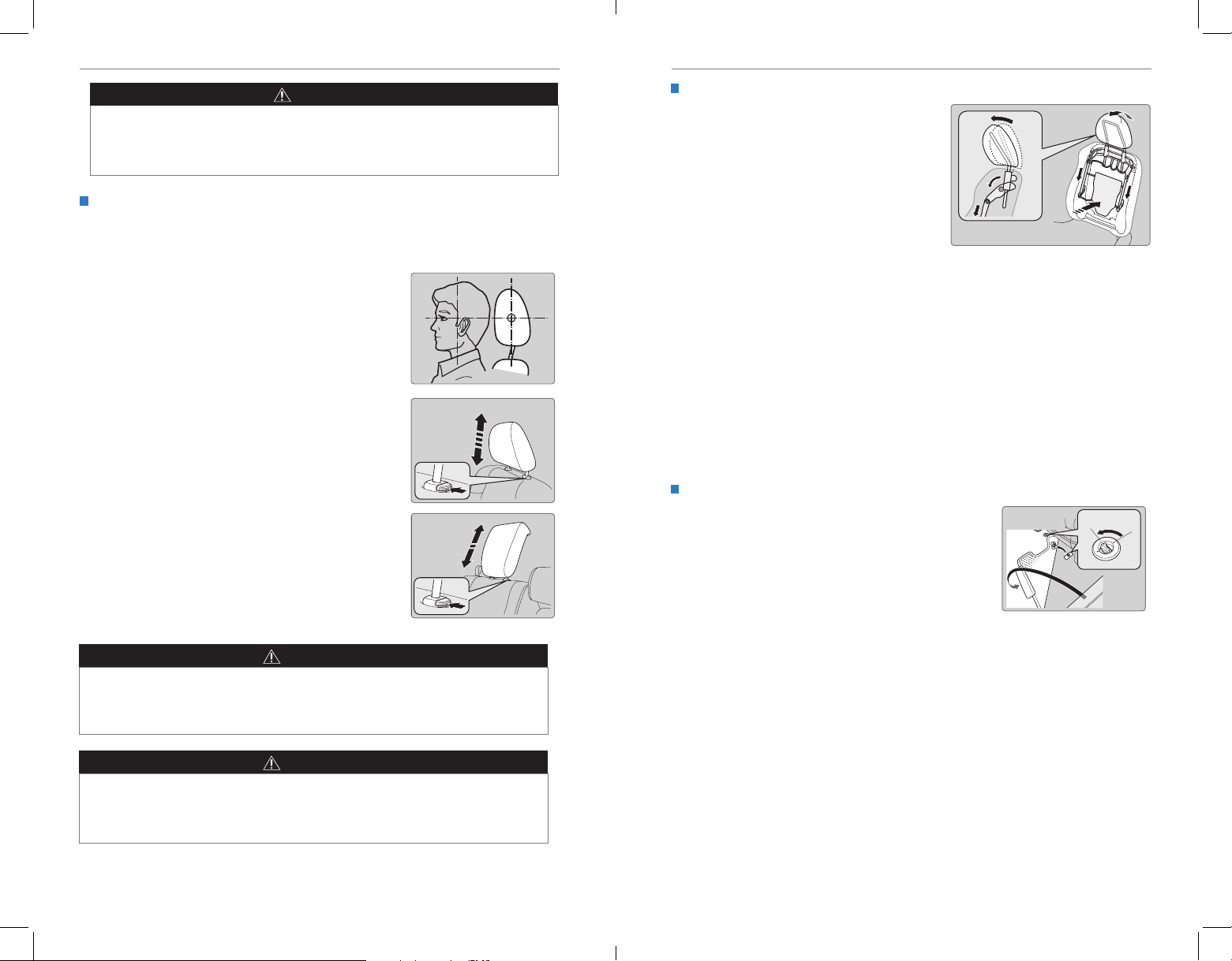
Adjusting the Head Restraints
Your vehicle is equipped with head restraints in all seating positions. Head
restraints are most effective for protection against whiplash and other rear-impact
crash injuries.
The center of the back of the occupant’s head
should rest against the center of the restraint. The
tops of the occupant’s ears should be level with the
center height of the restraint.
To raise the head restraint: Pull it upward.
To lower the head restraint: Push it down while
pressing the release button.
To remove the head restraint: Pull the restraint up
as far as it will go. Then push the release button,
and pull the restraint up and out.
To reinstall a head restraint: Insert the legs back
in place, then adjust the head restraint to an
appropriate height while pressing the release
button. Pull up on the restraint to make sure it is
locked in position.
Front seat
Second- or
third-row seat
Active Head Restraints
The driver’s and front passenger’s seats
have active head restraints. If the vehicle
is struck severely from the rear, the
occupant properly secured with the seat
belt will be pushed against the seat-back
and the head restraint will automatically
move forward.
This reduces the distance between the restraint and the occupant’s head. It also
helps protect the occupants against the likelihood of whiplash and injuries to the
neck and upper spine.
After a collision, the activated restraint should return to its normal position. If
the restraints do not return to their normal position, or in the event of a severe
collision, have the vehicle inspected by a Honda dealer.
For a head restraint system to work properly:
• Do not hang any items on the head restraints, or from the restraint legs.
• Do not place any object between an occupant and the seat-back.
• Install each restraint in its proper location.
Floor Mats
Position the front seat floor mats properly, and anchor
them. If they are not properly positioned, the oor
Front
(driver side)
To unlock
mats can interfere with the front seat functions.
Do not put additional floor mats on top of the
anchored mats.
WARNING
Improperly positioning head restraints reduces their effectiveness and
increases the likelihood of serious injury in a crash.
Make sure head restraints are in place and positioned properly before driving.
WARNING
Failure to reinstall, or correctly reinstall, the head restraints can result in
severe injury during a crash.
Always replace the head restraints before driving.
42 | | 43
Page 26
VEHICLE CONTROLSVEHICLE CONTROLS
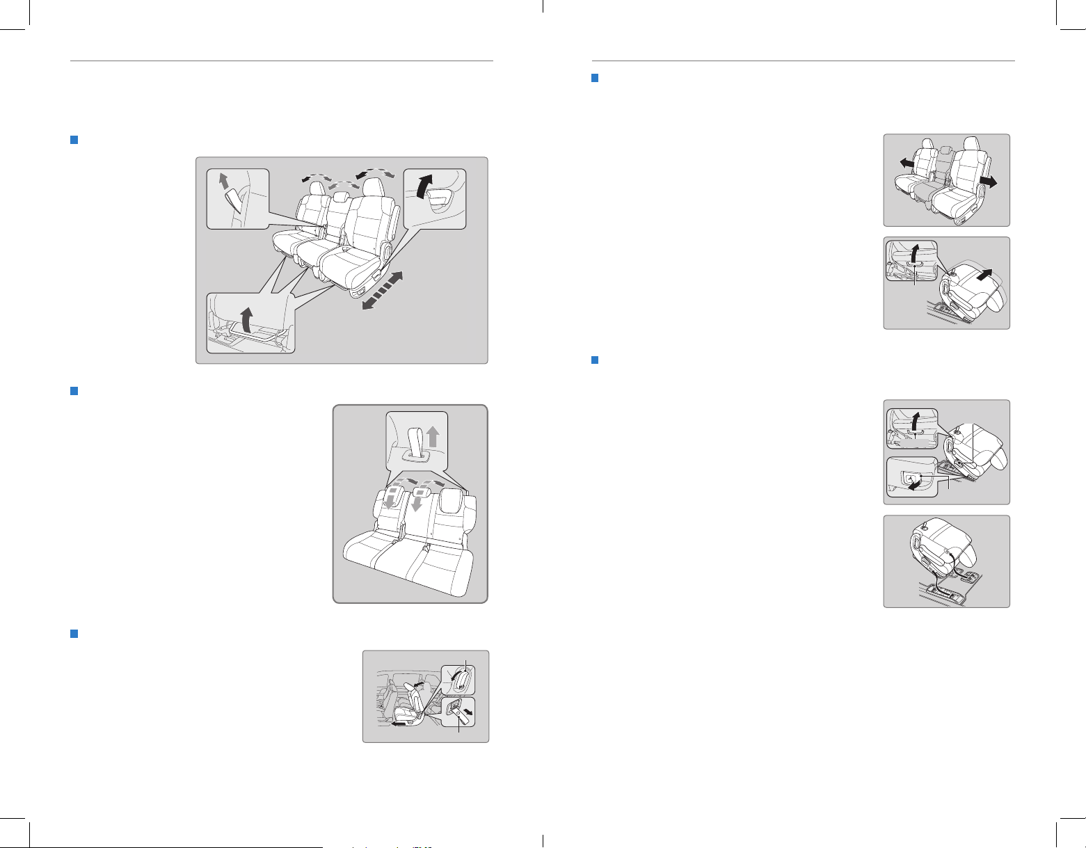
Rear Seats
Adjust second-row seats, access third-row seats, or remove seats for carrying
cargo.
Adjusting the Second-Row Passenger’s Seats
Second-row
passenger’s seats
can be adjusted
manually.
Seat-back angle
adjustment*
Pull the strap to
change the angle.
Horizontal position adjustment
Pull up the bar to move the seat,
then release the bar.
Adjusting the Third-Row Passenger’s Seats
Pull up the right strap to change the angle of
the right and center seat-backs, and the left
strap for the left seat-back.
Third-Row Seat Access
Pull up on the seat-back angle adjustment lever, or
pull the release strap to tilt the second-row outer
seat forward. Slide the whole seat forward.
Seat-back angle
adjustment
Pull up the lever
to change the
angle.
Lever
Sliding the Second-Row Seats Outward
The second-row outer seats can be moved outward slightly to allow two or three
child seats to be installed.
1. For the seat you want to move, lower the head
restraint to its lowest position.
2. Move the seat to its rearmost position.
3. Fold the seat-back down.
4. Pull the lock release lever, and grab the handle
under the rear side of the seat cushion to lift the
rear of the seat.
5. With the front of the seat hooked to the floor,
slide the seat to the outer position until it stops.
Handle
Slide
6. Lower the seat and push the rear of the seat-
back until it locks into place.
Removing a Second-Row Outer Seat
An outer second-row seat can be removed to increase storage and cargo space.
1. For the seat you want to remove, lower the head
restraint to its lowest position.
2. Move the seat to its rearmost position.
Handle
Seat-back angle
adjustment lever
3. Fold the seat-back down.
4. Pull the lock release lever, and grab the handle
under the rear side of the seat cushion to lift the
Lock release lever
rear of the seat.
5. Pull the seat-back slightly, then pivot it upward to
unhook the front of the seat from the floor.
6. Remove the seat.
To reinstall the seat: First hook the front of the
seat to the floor. Then, push the rear of the seat-
back until it locks into place.
Strap
*if equipped
44 | | 45
Page 27
VEHICLE CONTROLSVEHICLE CONTROLS
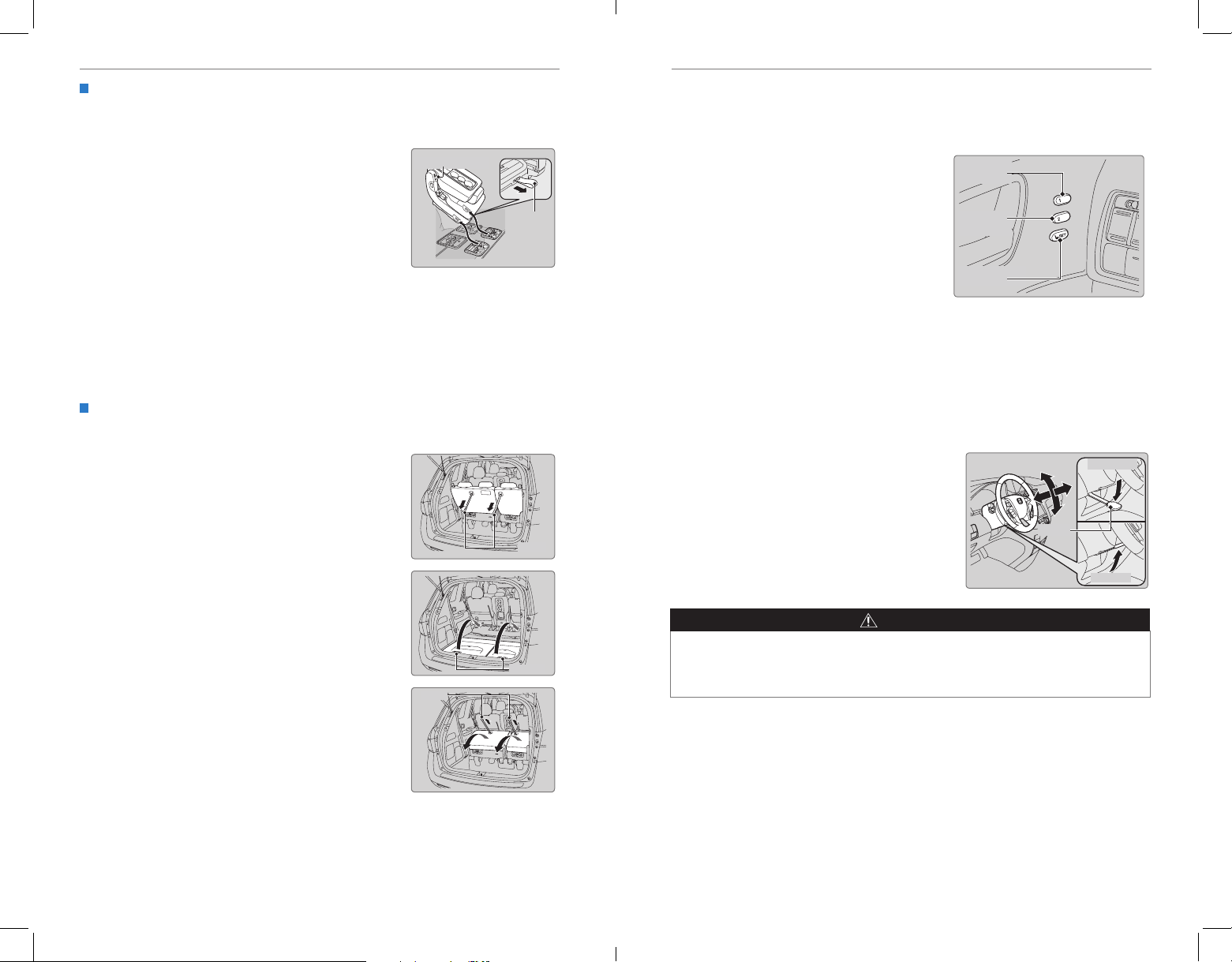
Removing a Second-Row Center Seat
The second-row center seat can be removed to increase storage and cargo space
or passenger mobility.
1. Store the center seat belt, and retract it into the
Adjustment strap
holder on the ceiling (see page 8).
2. Pull up the adjustment strap, and fold down the
seat-back.
3. Pull the lock release strap under the seat
Lock
release
strap
cushion, and hold the seat-back while lifting the
rear of the seat.
4. Pull the seat-back slightly, then pivot it upward to
unhook the front of the seat from the floor.
5. Remove the seat.
To reinstall the seat: First hook the front of the seat to the floor. Then, push the
rear of the seat-back until it locks into place.
Storing the One-Motion Third-Row Magic Seat
You can store the third-row seats to create a flat cargo area.
1. Store the center seat belt, and retract it into the
holder on the ceiling (see page 8).
2. Lower the head restraints to their lowest
positions.
Str aps
Driving Position Memory System*
You can store two driver’s seat and door mirror positions into memory when the
vehicle is on using the buttons on the driver’s door.
1. Adjust the seat and mirrors to your
preferred positions.
Memory
button 1
2. Press SET.
3. Press and hold memory button 1 or 2. You
will hear two beeps when the memory is set.
Memory
button 2
4. Press one of the memory buttons to recall
previously stored positions.
SET button
Lumbar positions cannot be stored.
When you unlock and open the driver’s door with a remote transmitter, the seat and
door mirrors adjust automatically to one of the two preset positions.
Adjusting the Steering Wheel
The steering wheel height and distance from your body can be adjusted so that you
can comfortably grip the steering wheel in an appropriate driving posture.
1. Pull up the steering wheel adjustment lever.
2. Move the steering wheel up or down, and in
or out.
3. Push down the steering wheel adjustment
lever to lock the steering wheel in position.
Lever
To adjust
To lock
3. Pull one or both straps to release the seats to a
flat position. Tuck the seats and straps into the
cargo area.
Str aps
Handles
Adjusting the steering wheel position while driving may cause you to lose
control of the vehicle and be seriously injured in a crash.
Adjust the steering wheel only when the vehicle is stopped.
WARNING
To reinstall the seats: Grab the outer handle, pull up
the folded seat, and pivot it forward. The front of the
seat automatically locks into place. Pull the strap to
return the seat-back to its upright position.
*if equipped
46 | | 47
Page 28
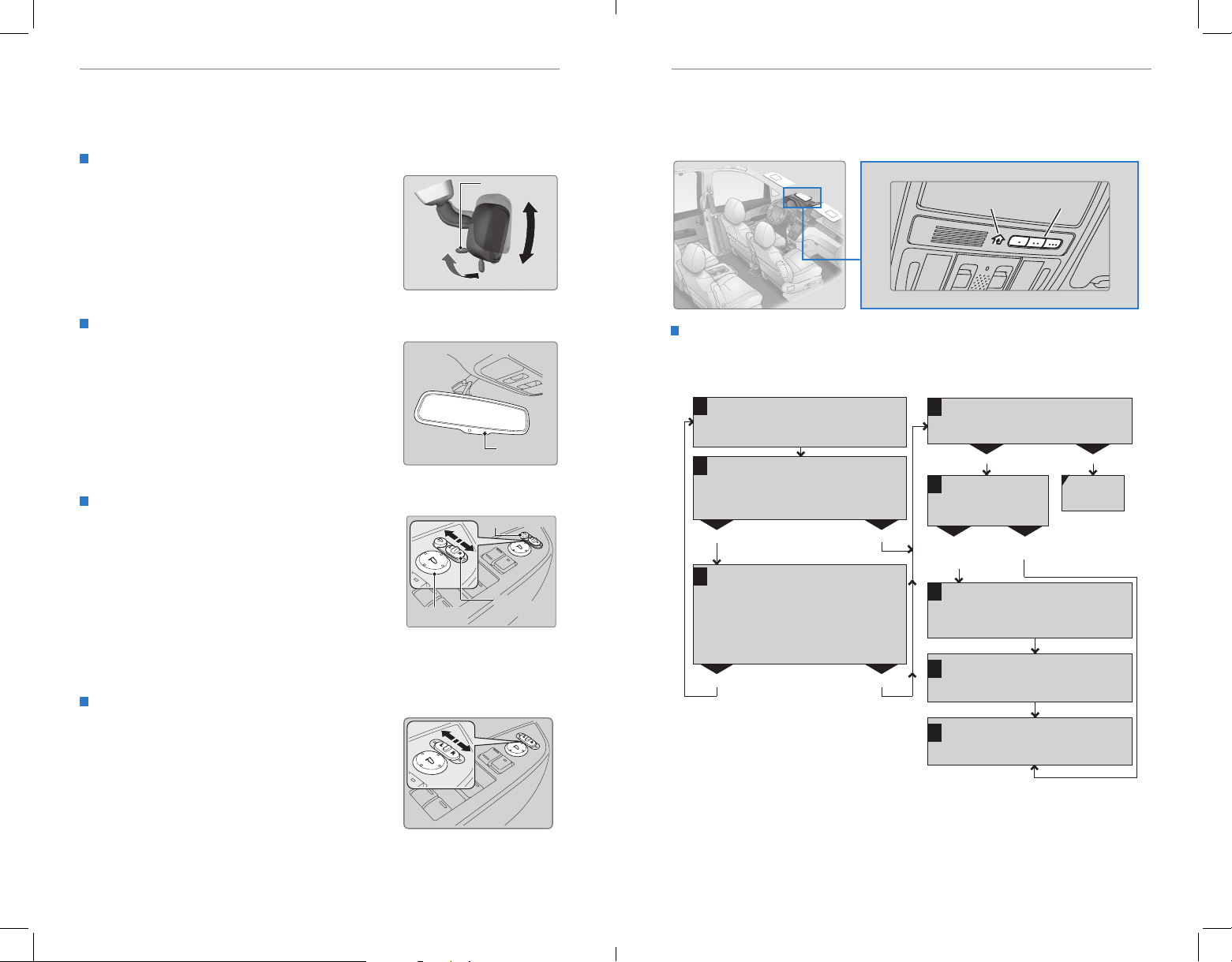
VEHICLE CONTROLSVEHICLE CONTROLS
Adjusting the Mirrors
Adjust the angle of the mirrors for the best visibility when you are sitting in the
correct driving position.
Rearview Mirror with Day/Night Positions*
Manually adjust the position to reduce headlight
glare from vehicles behind you. Flip the tab to switch
between day and night positions.
Automatic Dimming Rearview Mirror*
When driving after dark, the automatic dimming
function reduces the glare from headlights behind
you.
A green indicator appears when automatic dimming
is on. The function cancels when the shift lever is in
Reverse (R).
Power Door Mirrors
Adjust the power door mirrors when the vehicle is on.
L/R selector switch: Select the left or right mirror.
After adjusting the mirror, return the switch to the
center position.
Mirror position adjustment switch: Press the switch
left, right, up, or down to move the mirror.
Folding door mirror button*: Press to fold the door
mirrors in or out.
Reverse Tilt Door Mirrors*
Either side door mirror can tilt downward when
you shift to Reverse (R) to improve visibility on the
selected side of the vehicle when reversing. The
mirror returns to its original position when you shift
out of Reverse.
When in Reverse, slide the selector switch to the
left or right side.
Day
position
Adjustment switch
Tab
Down
Night position
Sensor
Folding button*
Selector
switch
*if equipped
HomeLink® Garage Opener*
Program your vehicle to operate up to three remote-controlled devices around
your home—such as garage doors, lighting, or home security systems—using the
buttons on the ceiling.
Up
HomeLink
indicator
Training a Button
Park near the system you want to program, and follow the instructions in the
owchart below.
1
Position the remote transmitter you wish to
link 1–3 inches (3–8 cm) from the HomeLink
button you want to program.
2
Press and hold the desired HomeLink button
and the button on the remote transmitter.
Does the HomeLink indicator (LED) blink at a
faster rate after about 10 seconds?
Press and hold the button on the remote and
a
the HomeLink button at the same time. Then,
while continuing to hold the HomeLink button,
press and release the button on the remote
every 2 seconds.
Does the LED blink at a faster rate within
20 seconds?
YESNO
YESNO
Press and hold the programmed HomeLink
3
button for about a second.
Does the device (garage door opener) work?
4
Press and hold the
HomeLink button
again.
HomeLink indicator
flashes for 2 seconds, then
remains on.
a
The remote has a rolling code. Press the
“learn” button on the remote-controlled
device (e.g., garage door opener).
Within 30 seconds, press and hold the
b
programmed HomeLink button for
2 seconds.
Press the programmed HomeLink button
5
again; the remote-controlled device should
operate.
To retrain a button or erase codes, see the Owner’s Manual on the Owner
Information CD or at owners.honda.com (U.S.) or www.myhonda.ca (Canada).
If you need help, call HomeLink at (800) 355-3515 or visit www.homelink.com.
HomeLink LED
remains on.
HomeLink
buttons
YESNO
Training
complete
*if equipped
48 | | 49
Page 29
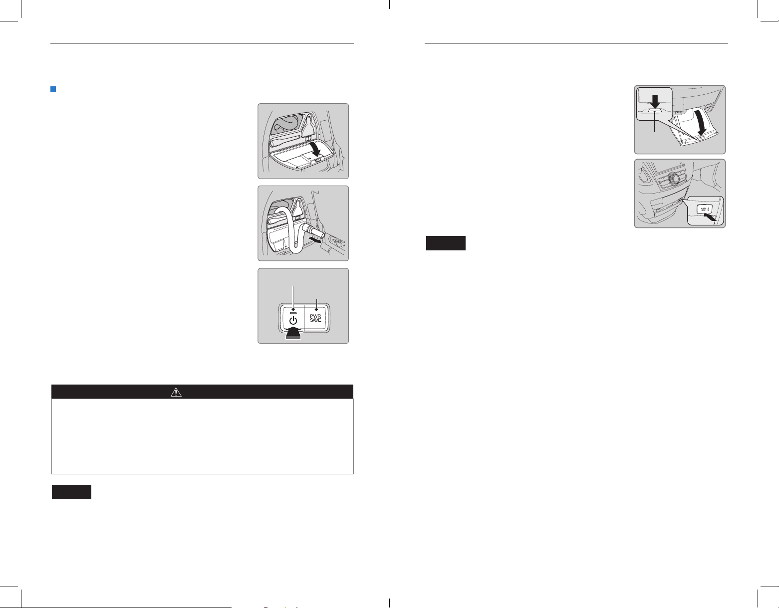
VEHICLE CONTROLSVEHICLE CONTROLS
HondaVAC®*
Clean up dry spills and debris inside your vehicle with the in-car vacuum system.
Operating the Vacuum
1. Make sure the vehicle is in Park (P). Set the
power mode to Accessory, or start the engine.
2. Open the vacuum storage lid in the driver’s side
rear cargo area.
3. Pull out the vacuum hose, and install one of the
attachments if desired.
4. Press the power button and begin to vacuum (dry
use only).
Accessory mode operation
• After 7 minutes, an intermittent beep begins to
sound as a time limit alert.
• After 8 minutes, a beep sounds, PWR SAVE comes
on, and the vacuum turns off. You must start the
engine if you want to continue using the vacuum.
The vacuum will restart after the engine has been
running for about one minute.
Engine on operation
Make sure you are using the vacuum in a well
ventilated, open area to minimize the likelihood of
carbon monoxide exposure.
Power
button
PWR SAVE
indicator
Cool Box*
Store items in a conveniently located box and keep them cool.
Press the button on the center pocket to open the box.
To turn on the Cool Box: Press COOL BOX. An indicator
light appears. Cold air from the air conditioning system
ows into and circulates within the box. Keep the box
closed during use for best results.
To turn off the Cool Box: Press the button again, or
turn the air conditioning system off.
The cool box is not a refrigerator and cannot be
removed for cleaning.
NOTICE
Do not put opened cans, uncovered containers, or loose ice inside the cool box.
Spilled liquids can damage the upholstery and electrical components in and
around the cool box.
Open
button
See the Owner’s Manual on the Owner Information CD or at owners.honda.com
(U.S.) or myhonda.ca (Canada) for instructions on emptying the canister.
WARNING
Engine exhaust contains toxic carbon monoxide that builds up rapidly in
enclosed areas. Breathing it can cause unconsciousness and even kill you. If
running the engine to power the vacuum, park the vehicle outdoors and lower
all windows to ensure adequate ventilation.
Do not vacuum ammable liquids or in an area with ammable vapors. A re or
explosion could result, causing death or serious injury.
NOTICE
The vacuum is intended for dry use only. Water and other liquids can damage the
vacuum.
*if equipped
50 | | 51
*if equipped
Page 30
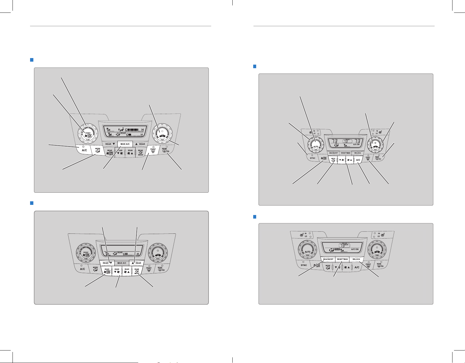
VEHICLE CONTROLSVEHICLE CONTROLS
Air Conditioning System*
Manually control the front and rear heating and cooling in your vehicle’s interior
using the buttons on the dashboard.
Front Operation
Fan control
dial
On/Off
button
A/C
button
MODE button:
Change airflow
location.
Rear Operation
MAX A/C
button
Recirculation button:
Recirculation mode (indicator on):
Recirculates air from the vehicle’s
interior.
Fresh Air mode (indicator off):
Maintains outside ventilation.
Windshield
defroster button
Rear defogger/
heated door
mirrors button*
Temperature
control dial
Climate Control System*
The automatic climate control system can maintain your preferred interior
temperature by selecting the proper mix of heated or cooled air and fan speed. Use
the buttons on the dashboard to control both front and rear operation.
Front Operation
AUTO button: Press, then use
the temperature control dial to
set your preferred temperature.
Driver’s side
temperature
control dial
SYNC button: Set
the passenger’s
side temperature
to the same as
the driver’s side.
ON/OFF
button
Mode button:
Change airflow
location.
Fan control
buttons
Recirculation button:
Recirculation mode (indicator on):
Recirculates air from the vehicle’s
interior.
Fresh Air mode (indicator off):
Maintains outside ventilation.
Passenger’s side
temperature
control dial
Rear defogger/
heated door
mirrors button*
A/C
button
Windshield
defroster
button
Rear temperature
down button
Rear On/Off
button
52 | | 53
Rear fan control
buttons
Rear temperature
up button
Rear mode
button
*if equipped
Rear Operation
Rear On/Off
button
Rear Settings button:
Turn the rear controls
on, then press to adjust
rear temperature.
Rear lock button:
Disable rear control.
*if equipped
Page 31
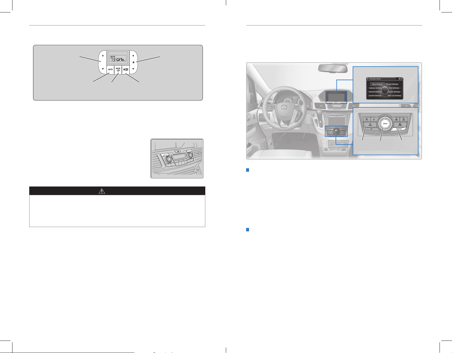
VEHICLE CONTROLSVEHICLE CONTROLS
You can also operate the rear climate control using the rear controls located on
the ceiling above the right second-row passenger.
Rear temperature
control bar
Rear AUTO
button
Rear MODE
button
Rear ON/OFF
button
Rear fan
control bar
Seat Heaters*
Quickly warm the front seats when the vehicle is on. The appropriate indicator
appears for each setting.
Press the seat heater button on the dashboard to
cycle through low, high, and off.
LO: Slowly warm the seat, or to maintain continuous
heating.
HI: Quickly warm the seat. If left in HI, the heater cycles
on and off.
WARNING
Heat-induced burns are possible when using seat heaters.
Persons with a diminished ability to sense temperature (e.g., persons with
diabetes, lower-limb nerve damage, or paralysis) or with sensitive skin should
not use the seat heaters.
Customized Features
Use the Settings menus to customize certain features of your vehicle. The
customized settings are recalled every time you unlock the driver’s door with the
remote (Driver 1 or Driver 2). Settings are unique to each remote.
Settings display
BACK
Interface
button
dial
How to Change a Setting
The vehicle must be in Park (P) to select Vehicle Settings. Use the selector knob or
interface dial to make and enter selections.
1. Press SETTINGS.
2. Select an option (System, Vehicle, Camera, Audio, Phone, Info, or Navi*).
3. Select a setting option, and make your preferred changes.
4. Press BACK to exit the menus.
Setting the Clock
On vehicles without navigation, use the selector knob to adjust the time in the
clock display. On vehicles with navigation, the time is automatically set using GPS
signals.
1. Press SETTINGS.
2. Select System Settings (or Clock).
3. Select Clock Adjustment.
4. Rotate the interface dial to change the hour value. Press the interface dial to
select minutes, and rotate to change the value. Press the interface dial to exit
the screen.
5. Press BACK to exit the menus.
SETTINGS
button
*if equipped
54 | | 55
*if equipped
Page 32
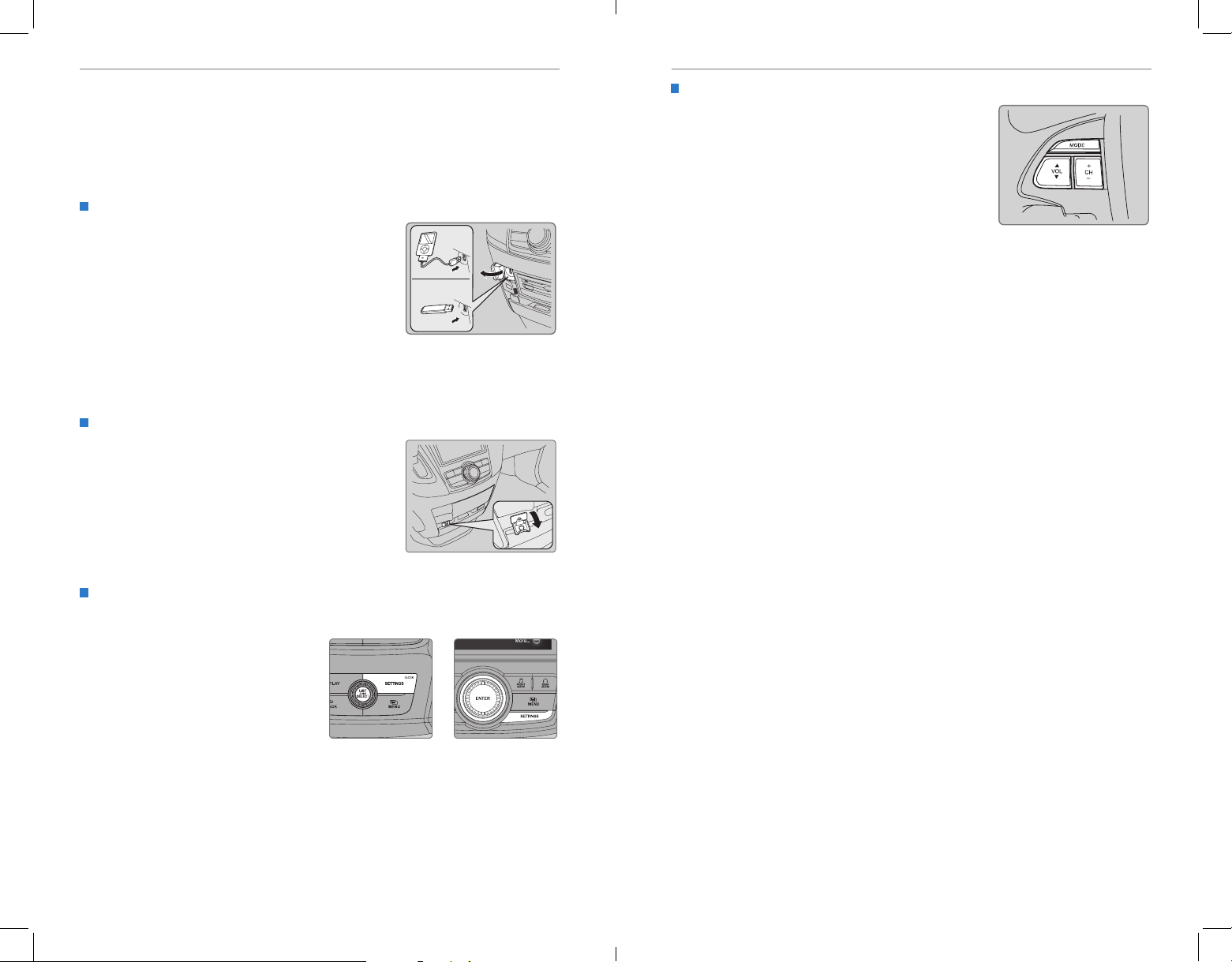
AUDIO AND CONNECTIVITYAUDIO AND CONNECTIVITY
AUDIO AND CONNECTIVITY
Learn how to operate the vehicle’s audio system.
Basic Audio Operation
Connect audio devices and operate buttons and displays for the audio system.
USB Port
Connect a USB flash drive or other audio device,
such as an iPod® or iPhone®. Install the ash drive
or cable connector to the USB port.
iPod and iPhone are trademarks of Apple, Inc.
State or local laws may prohibit the operation
of handheld electronic devices while operating a vehicle.
Auxiliary Input Jack
Connect standard audio devices with a 1/8-inch
(3.5 mm) stereo miniplug.
1. Open the AUX cover.
2. Insert the miniplug attached to the audio device
into the jack. The audio system switches to
AUX mode. Use the device to control the audio.
Steering Wheel Controls
You can operate certain functions of the audio
system using the steering wheel controls.
MODE button: Cycle through available audio modes.
CH buttons: Change presets, tracks, albums, or
folders.
VOL buttons: Adjust audio volume.
FM/AM/XM® Radio
Press (+) or (-) for the next or previous station.
Press and hold (+) or (-) for the next or previous strong station.
CD/HDD*/iPod®/USB/Bluetooth® Audio
Press (+) or (-) for the next or previous track.
Press and hold (+) or (-) for the next or previous folder (CD/USB).
Pandora
®
Press (+) for the next song.
Press and hold (+) or (-) for the next or previous station.
Adjusting the Sound
Adjust various sound settings using the selector knob.
1. Press SETTINGS.
2. Select Audio Settings.
3. Select Sound.
4. Select one of the options, and adjust
as necessary.
5. Press BACK to exit.
56 | | 57
Models with one
display
Models with two
displays
Page 33
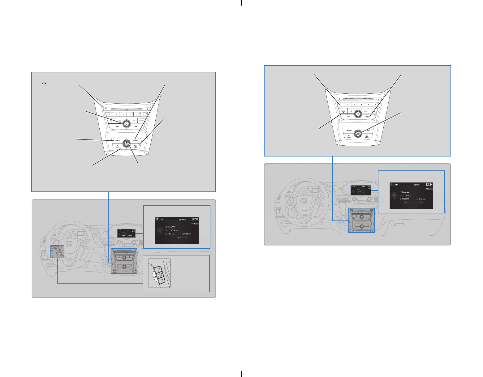
AUDIO AND CONNECTIVITYAUDIO AND CONNECTIVITY
Intelligent Multi-Information Display (i-MID)
Display audio or phone information. Use the buttons to control the display and audio
system.
Models with one display
button: Change
screen brightness.
Use the selector knob
to make adjustments.
Power/Volume knob:
Press to turn the audio
system on and off.
Turn to adjust the volume.
DISPLAY button:
Choose the audio
display, clock, or trip
computer.
BACK button: Go back to
the previous display.
Selector knob: Rotate to
scroll through options, and
press to enter a selection.
SETTINGS button:
Select various audio
mode options, sound
settings, and clock
adjustment.
MENU button:
Change audio options.
i-MID
FM/AM Radio
Play FM or AM radio stations.
Models with one display
Preset buttons (1-6):
Press and hold a preset
button to store the
current station. Press a
preset button to select
a previously stored
station.
FM/AM button: Select a
band.
Seek/Skip buttons:
Search up and down
the selected band for
a station with a strong
signal.
Selector knob: Press
and rotate to tune
radio frequency. Make
and enter selections.
FM/AM radio display
Display button:
Choose the
audio display,
clock, or trip
computer.
58 | | 59
Page 34
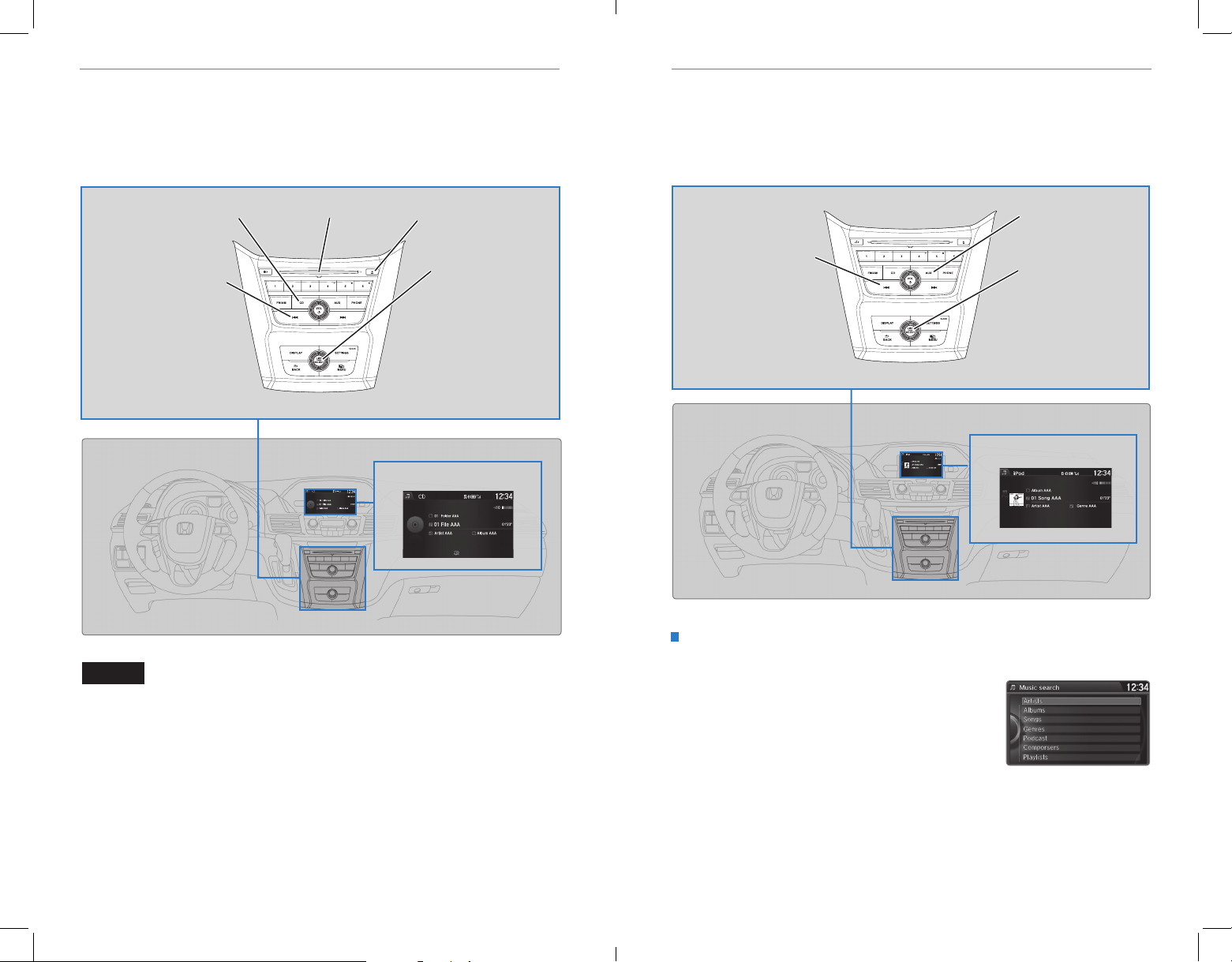
AUDIO AND CONNECTIVITYAUDIO AND CONNECTIVITY
Compact Disc (CD)
The audio system supports audio CDs, CD-Rs, and CD-RWs in MP3, WMA, or AAC
formats.
Models with one display
Play a CD.
Seek/Skip buttons: Press
to change tracks.
Press and hold to move
rapidly within a track.
CD eject buttonCD slotCD button:
Selector knob: Turn to
change tracks.
Press and turn to
select an item, then
press to set your
selection.
CD display
iPod® or USB Flash Drive
Play and operate an iPod or USB flash drive through the vehicle’s audio system.
Models with one display
Connect your device to the USB port (see page 56).
AUX button: Play iPod
or USB.
Seek/Skip buttons: Press
to change tracks.
Press and hold to move
rapidly within a track.
Selector knob: Turn to
change tracks.
Press and turn to
select an item, then
press to set your
selection.
iPod display
Searching for Music
Use the selector knob to search for tracks stored on the iPod or USB ash drive.
NOTICE
Do not use CDs with adhesive labels or insert a damaged CD. Inserting these types
of CDs may cause them to get stuck or damage the audio unit.
1. From the audio screen, press MENU.
2. Select Music Search.
3. Select a search option or folder.
4. Select the track you want to play.
iPod is a trademark of Apple, Inc.
60 | | 61
Page 35
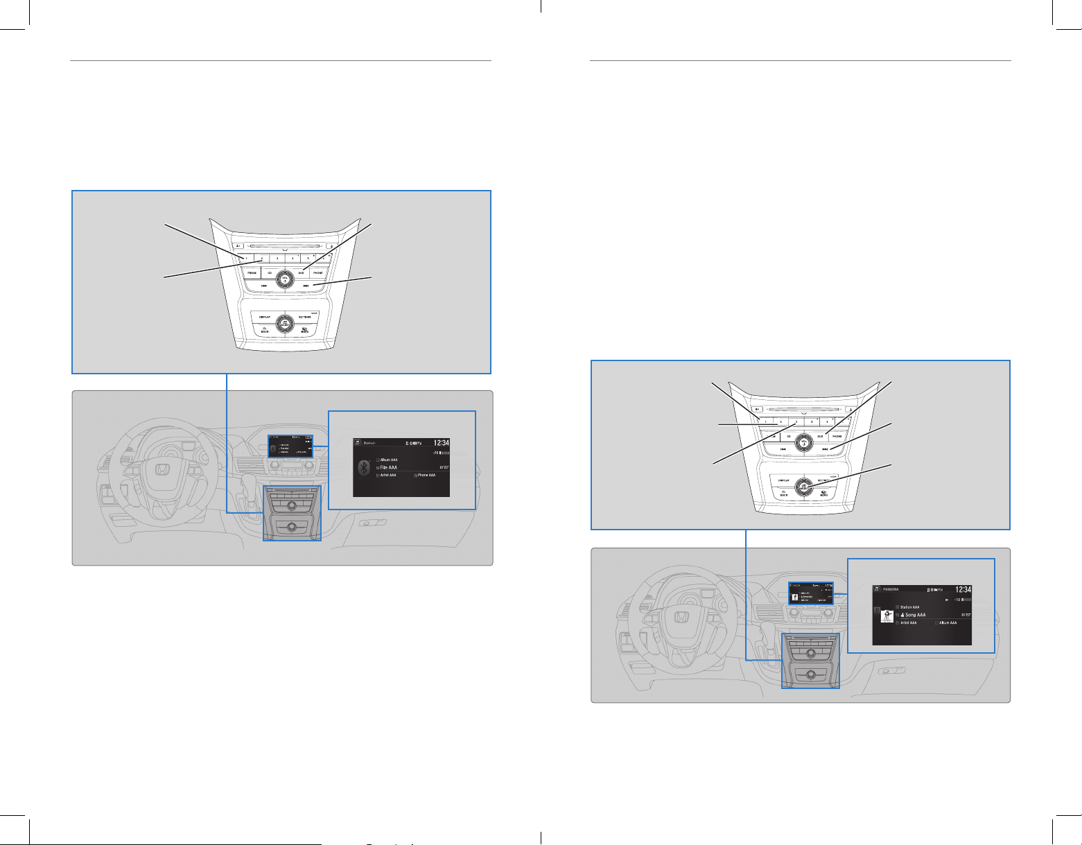
AUDIO AND CONNECTIVITYAUDIO AND CONNECTIVITY
Bluetooth® Audio
Play streaming or stored audio from your compatible phone through the vehicle’s
audio system. Visit handsfreelink.honda.com (U.S.) or www.handsfreelink.ca
(Canada) to check phone compatibility. Standard data rates apply.
Models with one display
Connect your phone to Bluetooth® HandsFreeLink® (see page 80).
Preset button 1:
Resume playing
audio.
Preset button 2:
Pause audio.
AUX button: Play
Bluetooth® Audio.
Seek/Skip buttons:
Change audio tracks.
Bluetooth® Audio display
Pandora
®
Play and operate Pandora from your phone through the vehicle’s audio system. Visit
handsfreelink.honda.com to check phone compatibility. Standard data rates apply.
Available in the U.S. only.
Models with one display
Connect your phone when the vehicle is stopped.
For iPhone:
• Connect via Bluetooth® HandsFreeLink® (see page 80) or USB port (see page 56).
• A pop-up may appear on your phone requesting you to allow access for Pandora to
be launched.
• If you cannot operate Pandora through the audio system, it may be streaming
through Bluetooth® Audio. Make sure Pandora is selected on the audio system.
• If Pandora still does not operate, try rebooting the phone and reconnecting the cable
if necessary.
For Android or BlackBerry:
• Connect via Bluetooth® HandsFreeLink® (see page 80).
Preset button 1: Pause
or resume songs.
Preset button 2: Like the
current song.
Preset button 3: Dislike
the current song.
AUX button: Play
Pandora.
Skip buttons: Go to the
next song.
Selector knob: Rotate to
change stations.
Pandora display
Notes:
• Make sure the volume on your phone is properly adjusted.
• You may need to enable additional settings on your phone for playback.
• The resume/pause function and remote audio controls are not supported on all phones.
State or local laws may prohibit the operation of
Only launch streaming audio on your phone when it is safe to do so.
62 | | 63
handheld electronic devices while operating a vehicle.
State or local laws may prohibit the operation of
handheld electronic devices while operating a vehicle.
Only launch streaming audio on your phone when it is safe to do so.
Page 36
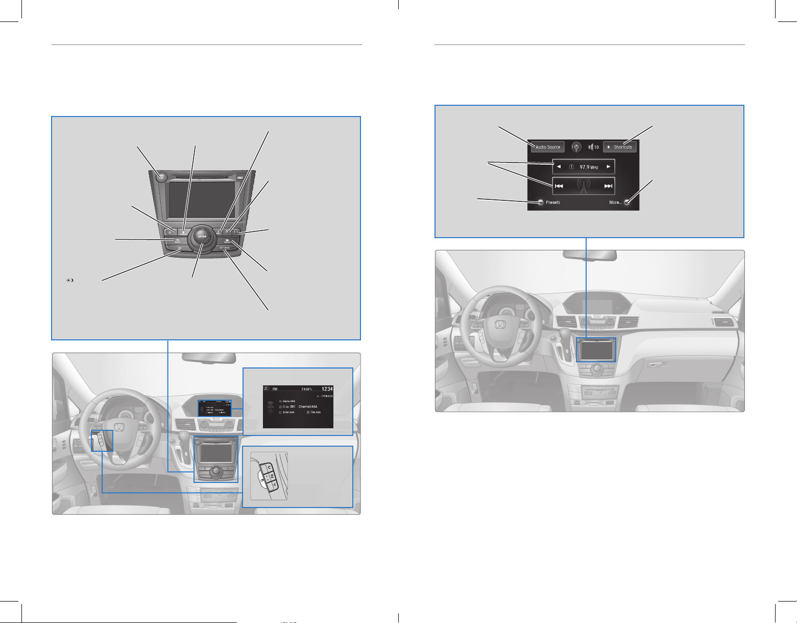
AUDIO AND CONNECTIVITYAUDIO AND CONNECTIVITY
REAR
AUDIO
FRONT
AUDIO
NAV
Intelligent Multi-Information Display (i-MID)
Display audio or phone information. Use the buttons to control the display and audio
system.
Models with two displays
Power/Volume knob:
Press to turn the audio
system on and off.
Turn to adjust the
volume.
NAV button*:
Display the map screen.
BACK button:
Go back to the
previous screen.
button:
Change screen
brightness. Use the
interface dial to make
adjustments.
PHONE button:
Display the phone screen.
Interface dial:
Move up, down, left, and
right. Rotate and press
ENTER to make selections in
the upper display.
INFO button:
Display the trip computer,
clock, and more.
FRONT AUDIO* (or
AUDIO) button:
Display the front audio
screen.
REAR AUDIO button*:
Display the rear audio
screen.
MENU button:
Change options for the
displayed mode.
SETTINGS button:
Change settings.
Touchscreen Operation
Select items on the touchscreen to operate certain audio functions.
Models with two displays
Audio Source:
Change the audio
source.
Skip/Seek:
Change stations,
albums, tracks, etc.
Presets:
Select or store
preset stations.
Shortcuts:
Store up to six AM, FM,
or XM stations or HDD*
tracks.
More:
Change sound or screen
settings, or options
for the selected audio
source.
i-MID
Display button:
Choose the
audio display,
clock, or trip
computer.
*if equipped
*if equipped
64 | | 65
Page 37
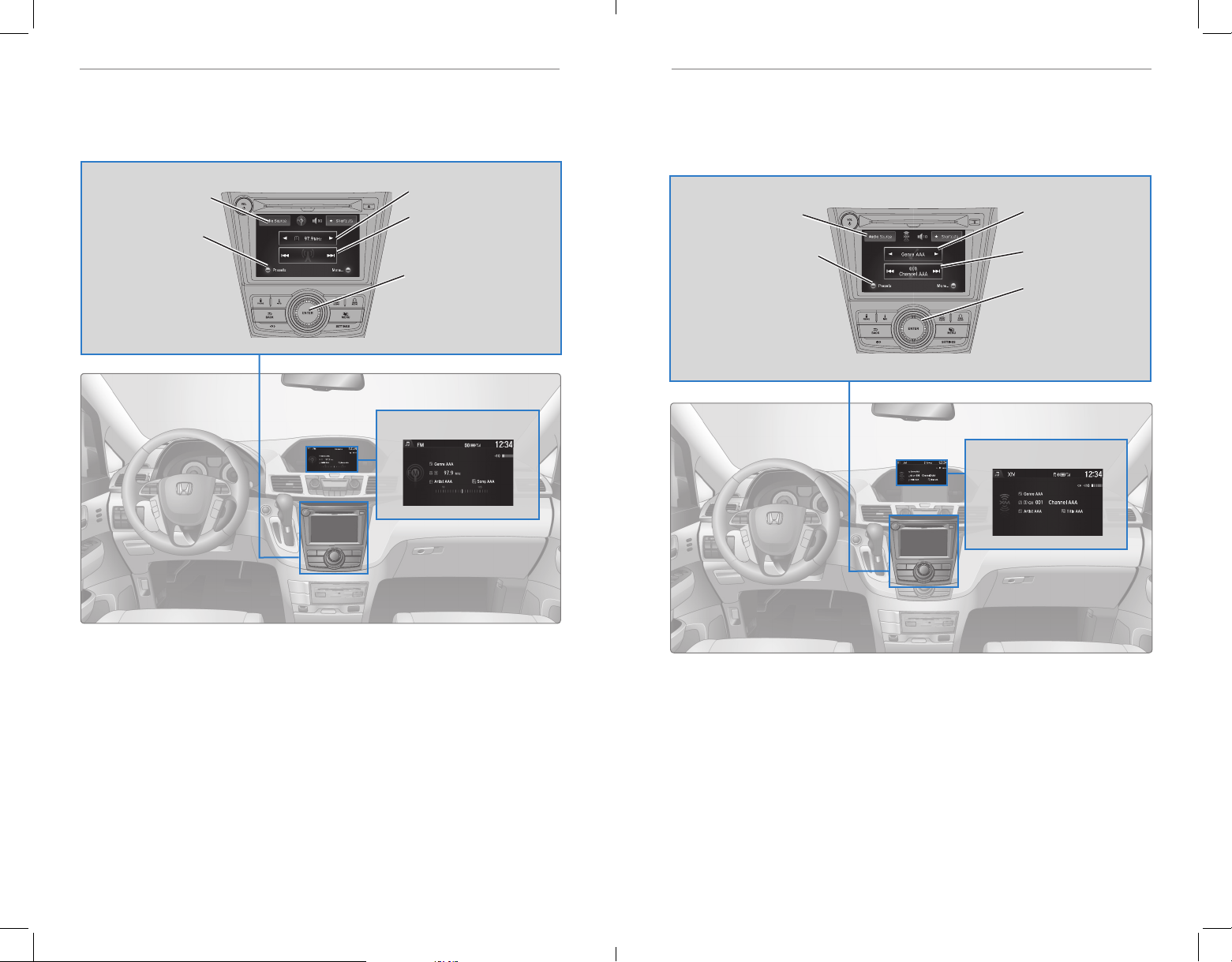
AUDIO AND CONNECTIVITYAUDIO AND CONNECTIVITY
FM/AM Radio
Play FM or AM radio stations.
Models with two displays
Audio Source: Select
the FM or AM icon.
Presets: Select and
hold a preset number
to store the current
station.
Select a preset number
to select a previously
stored station.
Tune: Change the station.
Skip/Seek: Search for the
next or previous station
with a strong signal.
Interface dial (from the
Audio screen): Rotate
and press to select preset
stations in the upper
display.
FM/AM radio display
SiriusXM® Radio
Available on a subscription basis only. For more information or to subscribe, contact
your dealer, or visit www.siriusxm.com (U.S.) or www.sirius.ca (Canada).
Models with two displays
Audio Source: Select
the XM icon.
Presets: Select and hold
a preset number to store
the current station.
Select a preset number to
select a previously stored
station.
Category bar: Change
the category.
Skip/seek bar: Change
the channel.
Interface dial (from
the Audio screen):
Rotate and press to
select preset stations
in the upper display.
XM Radio display
Available in the U.S. and Canada, except Hawaii, Alaska, and Puerto Rico.
66 | | 67
XM® is a registered trademark of Sirius XM Radio, Inc.
Page 38
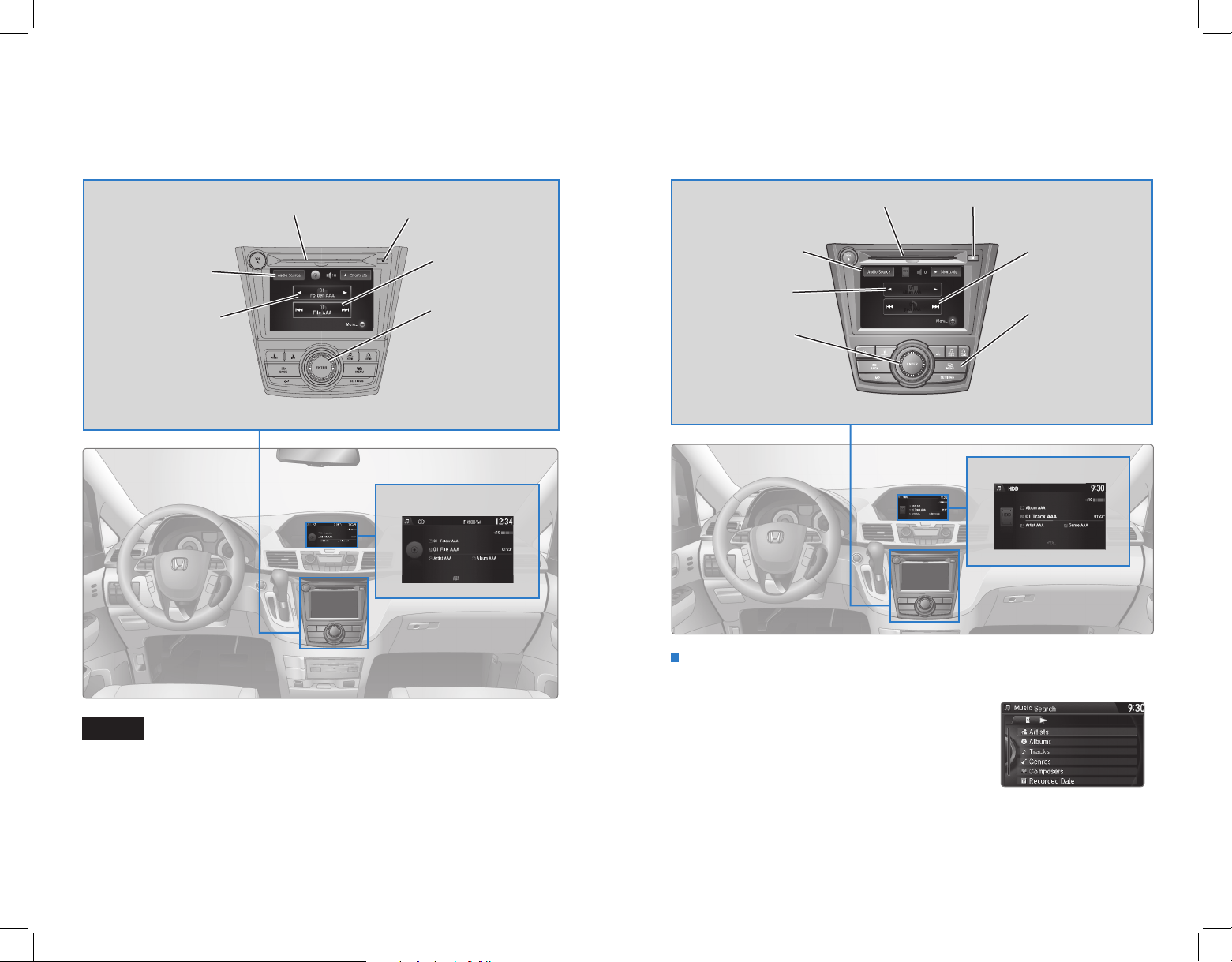
AUDIO AND CONNECTIVITYAUDIO AND CONNECTIVITY
NAV
Track AAA
Track AAA
0101
Album AAAAlbum AAA
01
01
Compact Disc (CD)
The audio system supports audio CDs, CD-Rs, and CD-RWs in MP3, WMA, or AAC
formats.
Models with two displays
CD slot
Audio Source: Select
the CD icon.
Folder bar: Change the
folder.
CD eject button
Skip/seek bar:
Change the track.
Interface dial (from
the Audio screen):
Rotate and press
to view and select
tracks in the upper
display.
CD display
Hard Disc Drive (HDD) Audio
Record CDs onto your vehicle’s hard drive. Songs are automatically recorded once a
CD is inserted.
Models with navigation
CD slot
Audio Source: Select
the HDD icon.
Album bar: Change
the album.
Interface dial (from
the Audio screen):
Rotate and press to
view and select tracks
in the upper display.
CD eject button
Skip/seek bar:
Change the track.
MENU button:
Change sound or
screen settings,
or options for the
selected audio
source.
HDD display
Searching for Music
Use the interface dial to search for tracks stored on the HDD.
1. From the audio screen, press MENU.
NOTICE
Do not use CDs with adhesive labels or insert a damaged CD. Inserting these types
of CDs may cause them to get stuck or damage the audio unit.
2. Select Music Search.
3. Select a search option.
4. Select the track you want to play.
You can also search for and play HDD music using Song By Voice™ (see page 149).
68 | | 69
Page 39
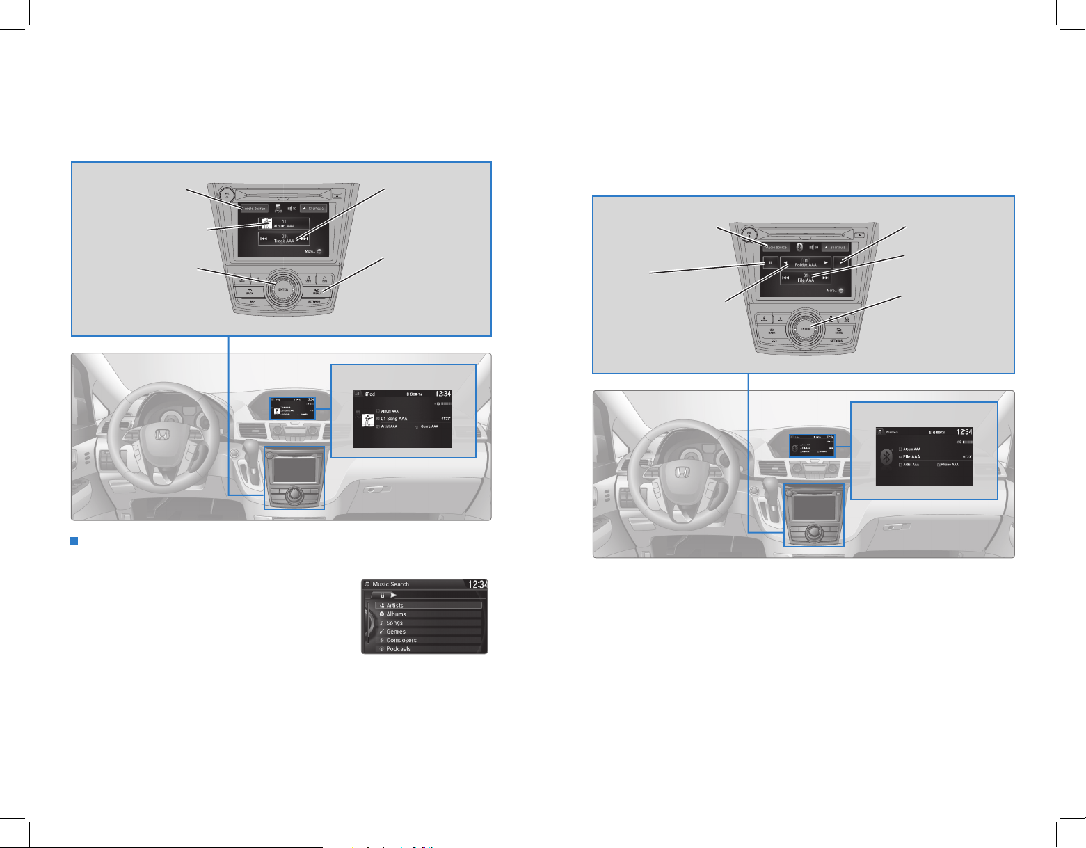
AUDIO AND CONNECTIVITYAUDIO AND CONNECTIVITY
iPod® or USB Flash Drive
Play and operate an iPod or USB flash drive through the vehicle’s audio system.
Models with two displays
Connect your device to the USB port (see page 56).
Audio Source: Select
the iPod or USB icon.
Album/folder bar: Change
the album or folder.
Interface dial (from the
Audio screen): Rotate and
press to view and select
tracks in the upper display.
Skip/seek bar:
Change the track.
MENU button:
Display menu items
in the upper display,
including Music
Search.
iPod display
Bluetooth® Audio
Play streaming or stored audio from your compatible phone through the vehicle’s
audio system. Visit handsfreelink.honda.com (U.S.) or www.handsfreelink.ca
(Canada) to check phone compatibility. Standard data rates apply.
Models with two displays
Connect your phone to Bluetooth® HandsFreeLink® (see page 80).
Audio Source: Select
the Bluetooth icon.
Pause
Folder bar: Search for a
folder.
Bluetooth® Audio display
Play
Seek/Skip: Go to the
next or previous track.
Interface Dial (from
the Audio screen):
Rotate and press to
select an item in the
upper display.
Searching for Music
Use the interface dial to search for tracks stored on the iPod or USB flash drive.
1. From the audio screen, press MENU.
2. Select Music Search.
3. Select a search option or folder.
Notes:
• Make sure the volume on your phone is properly adjusted.
• You may need to enable additional settings on your phone for playback.
• The resume/pause function and remote audio controls are not supported on all phones.
4. Select the track you want to play.
On vehicles with navigation, you can also search for and play iPod music using
Song By Voice™ (see page 149).
70 | | 71
Only launch streaming audio on your phone when it is safe to do so.
State or local laws may prohibit the operation of
handheld electronic devices while operating a vehicle.
Page 40
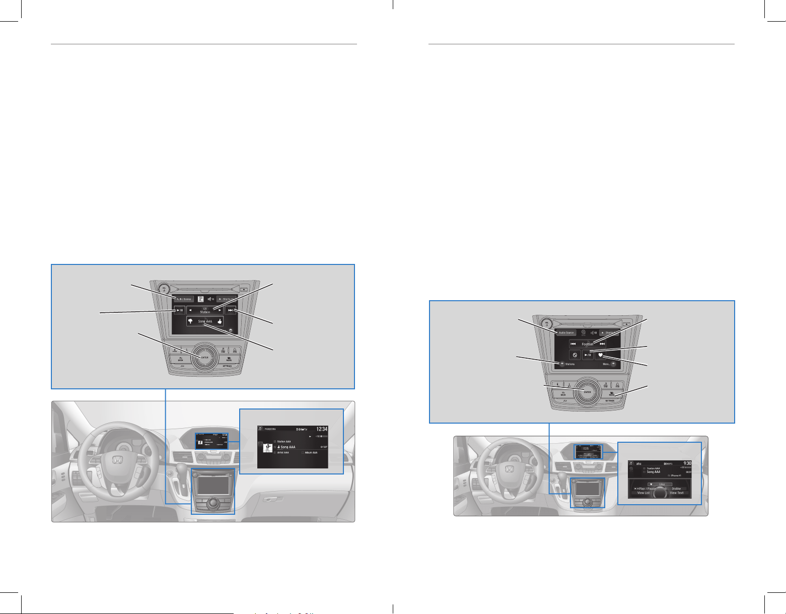
AUDIO AND CONNECTIVITYAUDIO AND CONNECTIVITY
Pandora
®
Play and operate Pandora from your compatible phone through the vehicle’s audio
system. Visit handsfreelink.honda.com to check phone compatibility. Standard data
rates apply. Available in the U.S. only.
Models with two displays
Connect your phone when the vehicle is stopped.
For iPhone:
• Connect via Bluetooth® HandsFreeLink® (see page 80) or USB port (see page 56).
• A pop-up may appear on your phone requesting you to allow access for Pandora to
be launched.
• If you cannot operate Pandora through the audio system, it may be streaming
through Bluetooth® Audio. Make sure Pandora is selected on the audio system.
• If Pandora still does not operate, try rebooting the phone and reconnecting the cable
if necessary.
For Android or BlackBerry:
• Connect via Bluetooth® HandsFreeLink® (see page 80).
Audio Source: Select
the Pandora icon.
Play/Pause
Interface dial (from the
Audio screen): Rotate and
press to select an item in
the upper display.
Station bar: Change
the station.
Skip: Go to the next
song.
Like/dislike song
Pandora® display
HondaLink featuring Aha™
Access music and information programming, location-based services, and social
media through your vehicle’s audio system. Visit handsfreelink.honda.com (U.S.)
or honda.ca/hondalink (Canada) to check phone compatibility. Standard data rates
apply.
Models with two displays
Visit www.hondalink.com (U.S.) or honda.ca/hondalink (Canada) and download the
HondaLink app to your phone prior to using this feature. Make sure you have an
active Aha account. Connect your phone when the vehicle is stopped.
For iPhone:
• Connect via Bluetooth® HandsFreeLink® (see page 80) or USB port (see page 56).
• A pop-up may appear on your phone requesting you to allow access for Aha to be
launched.
• If you cannot operate Aha through the audio system, it may be streaming through
Bluetooth® Audio. Make sure Aha is selected on the audio system.
• If Aha still does not operate, try rebooting the phone and reconnecting the cable if
necesary.
For Android or BlackBerry (U.S. only):
• Connect via Bluetooth® HandsFreeLink® (see page 80).
Audio Source: Select
the Aha icon.
Stations: Select from
16 previously favorited
stations.
Interface dial (from the Audio
screen): Rotate and press to
view and select menu items.
Station bar: Change the
station.
Play/Pause
Like/dislike
MENU button: View the
complete station list in
the upper display.
Aha™ display
State or local laws may prohibit the operation of
Only launch streaming audio on your phone when it is safe to do so.
72 | | 73
handheld electronic devices while operating a vehicle.
Only launch streaming audio on your phone when it is safe to do so.
State or local laws may prohibit the operation of
handheld electronic devices while operating a vehicle.
Page 41
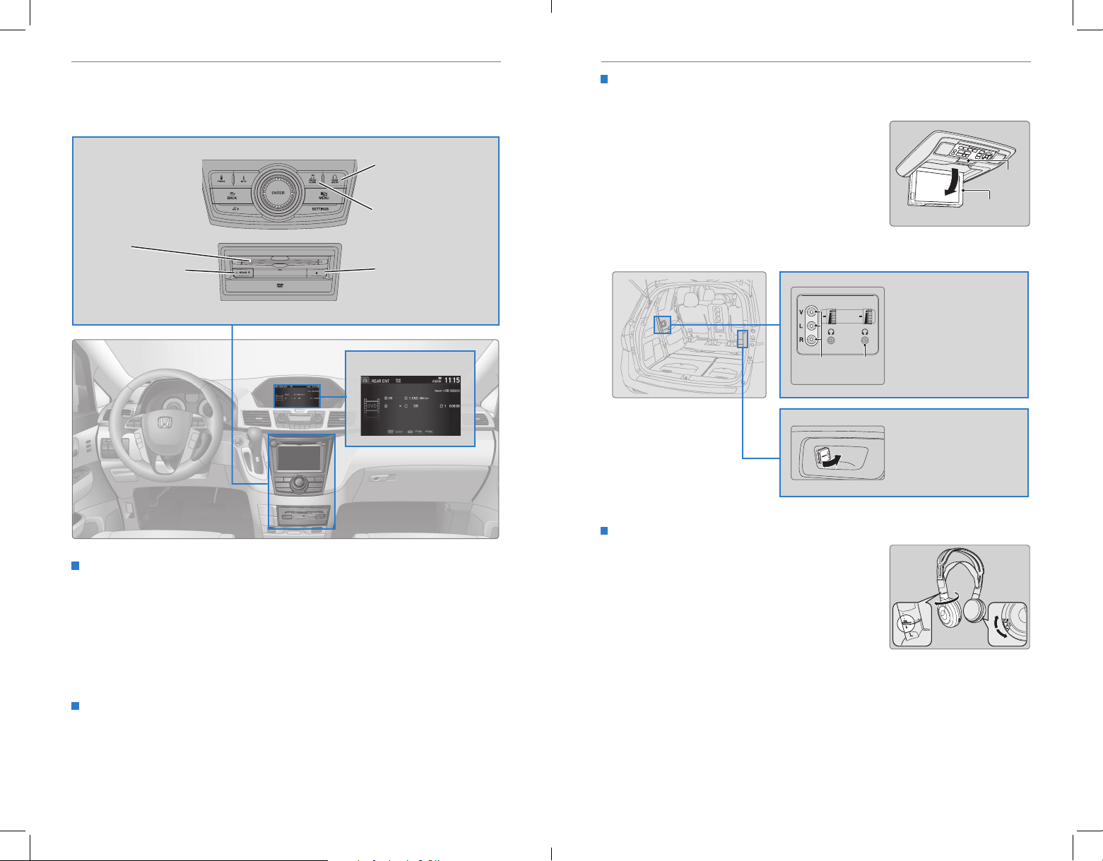
AUDIO AND CONNECTIVITYAUDIO AND CONNECTIVITY
Rear Entertainment System (RES)*
Rear passengers can enjoy a different audio or entertainment source than front
passengers.
REAR AUDIO button:
Display rear audio
information.
FRONT AUDIO button:
Display front audio
DVD slot
REAR POWER button:
Turn the rear entertainment
system on or off.
information.
DVD eject button
Rear audio display
System Components
Open the overhead screen to use the system.
9-inch screen*: Pull down the bottom edge of the
screen, and extend it until it locks into place.
Ultrawide screen*: Press OPEN. Extend the screen
until it locks into place.
Fold the screen back into the ceiling when not in
use.
Press the release button to detach the rear control
panel, if desired.
Auxiliary
input jack
Headphone
jack
Release
button
Overhead
screen
Auxiliary inputs can be used
for video game systems and
other devices.
Wired headphones can also
be used.
Ultrawide RES*
HDMI input can be used for
video game systems and
other devices.
Wireless Headphones
Your vehicle comes with two sets of wireless
Operating the System from the Front
You can operate the rear entertainment system using the front audio controls.
1. Press REAR POWER to turn the system on.
headphones.
Pivot the left earpiece to turn on the headphones.
Turn the dial at the bottom of the right earpiece to
adjust the volume.
Pivot to
turn on.
Volume
dial
2. Press REAR AUDIO.
3. Use the front audio controls to choose a media source for the rear system.
4. Press FRONT AUDIO to return to the front audio source.
Playing a DVD
Insert a DVD into the DVD slot. It begins playing automatically. Use the front or
rear controls to navigate the DVD.
*if equipped
74 | | 75
*if equipped
Page 42
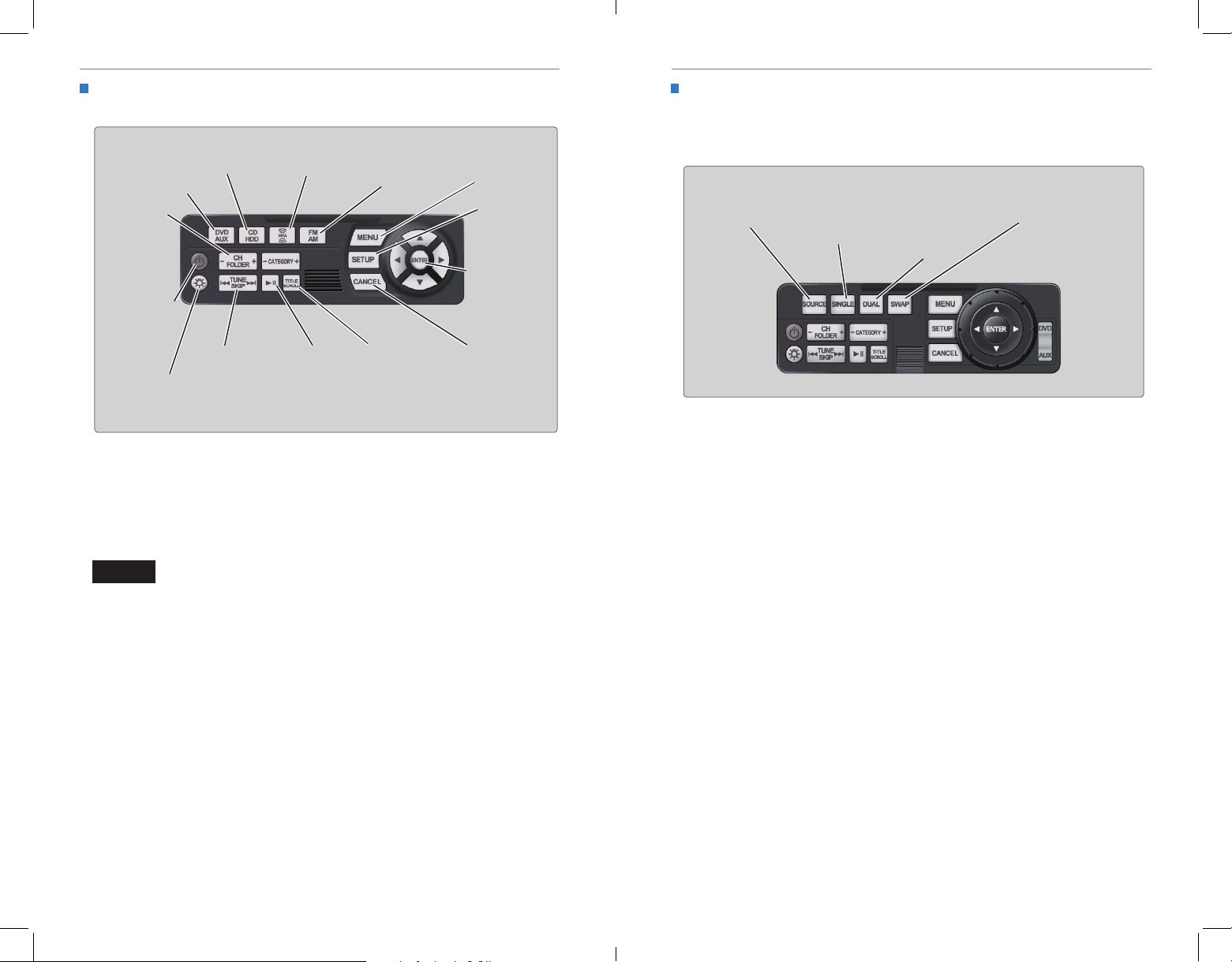
AUDIO AND CONNECTIVITYAUDIO AND CONNECTIVITY
Remote Control and Rear Operation
You can operate the system using the rear control panel.
DVD/AUX button:
Play a DVD, USB,
iPod, or auxiliary
source.
CH/FOLDER
button:
Change
channels,
stations, or
folders.
Power button:
Turn the
system on or
off.
Light button:
Illuminate the
remote buttons.
CD button:
Play a CD.
TUNE/SKIP
button: Change
DVD chapters,
audio stations,
or tracks.
XM button*:
Play XM Radio.
Play/Pause
button
(CD or DVD)
FM/AM button:
Play FM or AM
Radio.
TITLE/SCROLL
button: Display
the DVD status
or CD titles.
MENU button:
Display menu
options.
SETUP button:
Display setup
options.
Arrow/ENTER
button: Highlight
and select items.
CANCEL button:
Go back to the
previous display.
1. Make sure REAR POWER is turned on in the front audio controls.
2. From the rear control panel, press the desired audio source button (or the
SOURCE button for Ultrawide RES*).
3. Press the arrow/ENTER buttons to highlight options on the screen and select
them. Use the other rear control panel buttons to operate the system.
Ultrawide Dual Screen Operation*
Play two different sources side by side on the ultrawide screen. One side of the
screen can play a source from the front audio system (FM, DVD, etc.). The other
side of the screen can play a connected device, such as a video game system.
SOURCE button:
Display audio
sources.
SINGLE button:
Display one
source on the
entire screen.
DUAL button:
Display two
sources side
by side on the
screen.
SWAP button:
Switch the
sources to
opposite sides of
the screen.
1. Connect a second source through the rear auxiliary or HDMI input (see
page 75).
2. From the rear control panel, press DUAL.
3. Select which side the second source plays on.
4. Press SOURCE to select AUX-VIDEO or AUX-HDMI.
NOTICE
This vehicle’s overhead mounted display includes mercury-containing
components. Upon removal or replacement, please reuse, recycle, or dispose of
as hazardous waste.
*if equipped
76 | | 77
*if equipped
Page 43
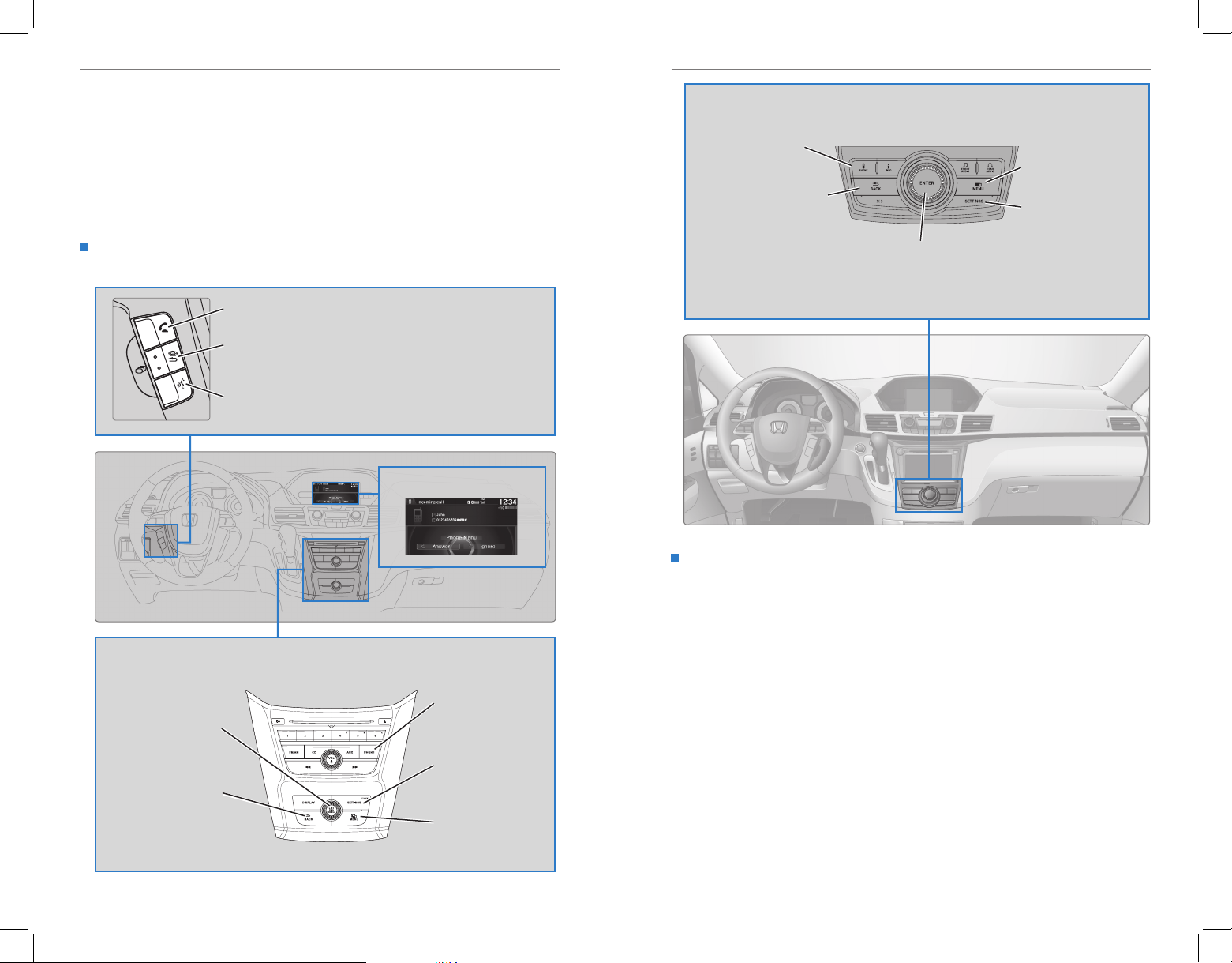
BLUETOOTH® HANDSFREELINK
®
BLUETOOTH® HANDSFREELINK
®
BLUETOOTH® HANDSFREELINK® (HFL)
Learn how to operate the vehicle’s hands-free calling system.
Basic HFL Operation
Make and receive phone calls using the vehicle’s audio system, without handling
your phone. Visit handsfreelink.honda.com (U.S.) or www.handsfreelink.ca (Canada)
to check phone compatibility.
HFL Controls
Use the controls to enter information and make selections.
Pick-Up button: Answer an incoming call.
Hang-Up/Back button: End or decline a call, or cancel an
operation.
Talk button: Make a call using a stored voice tag, phonebook
name, or phone number.
HFL display
Models with two displays
PHONE button: Display
the phone screen.
BACK button: Go back to
the previous display.
Interface dial (from the Phone
screen): Rotate and press to make
selections in the upper display. Move
up, down, left, or right.
MENU button: Display
menu items.
SETTINGS button:
Display phone settings.
Voice Recognition Tips
On models with navigation, you can say voice commands to operate system
functions. Below are some helpful tips:
• When using the Talk button, wait for a beep before saying a command.
• To bypass the system prompts, simply press the Talk button again to say your
Models with one display
command.
• When the Talk button is pressed, all available voice commands are highlighted
PHONE button:
Selector knob: Rotate
and press to make
selections.
BACK button: Go back
to the previous display.
78 | | 79
Display the phone
screen.
SETTINGS button:
Display phone
settings.
MENU button: Display
menu items.
in yellow.
• Speak in a clear, natural voice.
• Reduce all background noise.
• Adjust the dashboard and side vents away from the microphone in the ceiling.
• Close the windows and moonroof.
To reduce the potential for driver distraction, certain manual functions may be
inoperable or grayed out while the vehicle is moving. Stop or pull over to perform
the function.
Page 44
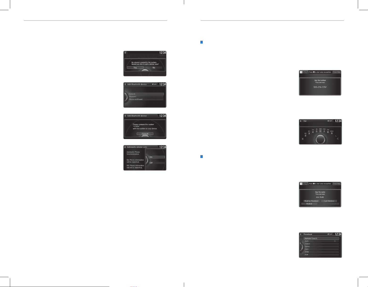
BLUETOOTH® HANDSFREELINK
®
BLUETOOTH® HANDSFREELINK
®
Pairing a Phone
To use hands-free phone and streaming audio functions, you must first pair your
phone to the system. This can only be done when the vehicle is stopped. Use the
selector knob or interface dial to make and enter selections.
1. Press SETTINGS.
2. Select Phone Settings.
3. Select Bluetooth Device List (if no phone has been
paired) or Connect Phone (if pairing an additional
phone).
4. Select Add Bluetooth Device.
5. Make sure your phone is in discovery mode.
6. HFL searches for your phone. Select your phone
when it appears on the list.
If your phone does not appear:
Select Phone Not Found and search for
HandsFreeLink from your phone.
7. HFL gives you a six-digit code. Compare it to the
code that appears on your phone. Connect to HFL
from your phone.
Making a Call
You can make a call using several methods.
Dialing a Number
Enter a 10-digit phone number to call.
Using voice commands
Press the Talk button before you say each command.
1. Say “Dial by number.”
2. Say the phone number. For example,
“3-1-0-5-5-5-1-2-3-4.”
3. The system begins to dial.
Using the menu
Use the selector knob or interface dial to make and enter selections. This method
is inoperable while the vehicle is moving.
1. Press PHONE.
2. Press MENU.
3. Select Dial.
4. Enter the phone number. Select the green phone
icon to call.
8. The system asks if you want to enable Phone
Synchronization, which imports your phone’s call
history and phonebook. Select On.
9. Press BACK to exit the menu.
State or local laws may prohibit the operation of
handheld electronic devices while operating a vehicle.
Using the Phonebook
When your phone is paired, its entire phonebook can be automatically imported to
the system. Phone synchronization must be turned on.
Using voice commands
Press the Talk button before you say each command.
1. Say “Dial by name.”
2. Say the phonebook name and phone type. For
example, “John Smith mobile.”
Using the menu
Use the selector knob or interface dial to make and enter selections. This method
is inoperable while the vehicle is moving.
1. Press PHONE.
2. Press MENU.
3. Select Phonebook.
4. Scroll through the list to find the name and
number you want to call, and select it to call.
80 | | 81
Page 45
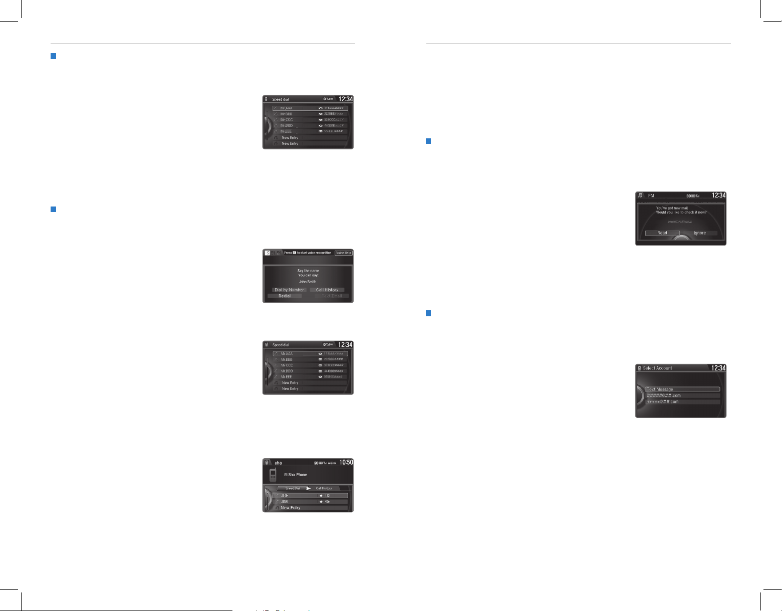
BLUETOOTH® HANDSFREELINK
®
BLUETOOTH® HANDSFREELINK
®
Storing Speed Dial Entries
Mr.AAA
111AAA####
555EEE####
444DDD####
333CCC####
222BBB####
Mr.EEE
Mr.DDD
Mr.CCC
Mr.BBB
Mr.AAA
111AAA####
555EEE####
444DDD####
333CCC####
222BBB####
Mr.EEE
Mr.DDD
Mr.CCC
Mr.BBB
Store up to 20 numbers for quick dialing. Use the selector knob or interface dial to
make and enter selections.
1. Press PHONE.
2. Press MENU.
3. Select Speed Dial, then select New Entry.
4. Select an entry method.
5. If desired, you can create a voice tag for the
number. Follow the prompts.
When a voice tag is created, you can press the Talk button and say “Call” and
the stored voice tag to quickly call the number.
Using Speed Dial and Call History
Make calls quickly using stored speed dial entries or call history numbers.
Using voice commands
Press the Talk button before you say each command.
1. Say “Dial by voice tag.”
2. Say the stored voice tag name. For example,
“John Smith.”
Models with one display
Using the menu
1. Press PHONE.
2. Press MENU.
3. Select Speed Dial or Call History.
4. Scroll through the list to find the entry you want
to call, and select it to call.
Models with two displays
Using the phone screen
Use the interface dial to make and enter selections.
SMS Text Messaging and E-Mail*
Receive and send messages from your paired and connected phone. Visit
handsfreelink.honda.com (U.S.) or www.handsfreelink.ca (Canada) to check phone
compatibility. Standard message rates apply. This feature is limited while the vehicle
is moving.
Models with two displays
Receiving and Responding to Messages
When you receive a new message, a pop-up appears on the display. Use the
selector knob or interface dial to view the message when the vehicle is stopped.
You can also reply to it using fixed phrases or call the sender.
1. When the prompt appears, select Read.
2. The message is displayed, and the system reads
it aloud.
On models with one display, press the selector
knob to display the options.
To reply: Select Reply, and choose one of the six
available responses. Select Send to send the
message. You cannot create a new text message.
To call the sender: Select Call.
Selecting an Account
If your phone has both text message and e-mail accounts, you can select only
one of them at a time to be active and receive notications. Use the interface dial
make and enter selections.
1. Press SETTINGS.
2. Select Phone Settings.
3. Select Select Account.
4. Select Text Messages or an e-mail account.
1. Press PHONE.
2. For Speed Dial, use the interface dial to scroll
through the list to find the entry you want to call,
and select it to call.
For Call History, move the interface dial to the
right and scroll through the list.
*if equipped
82 | | 83
Page 46
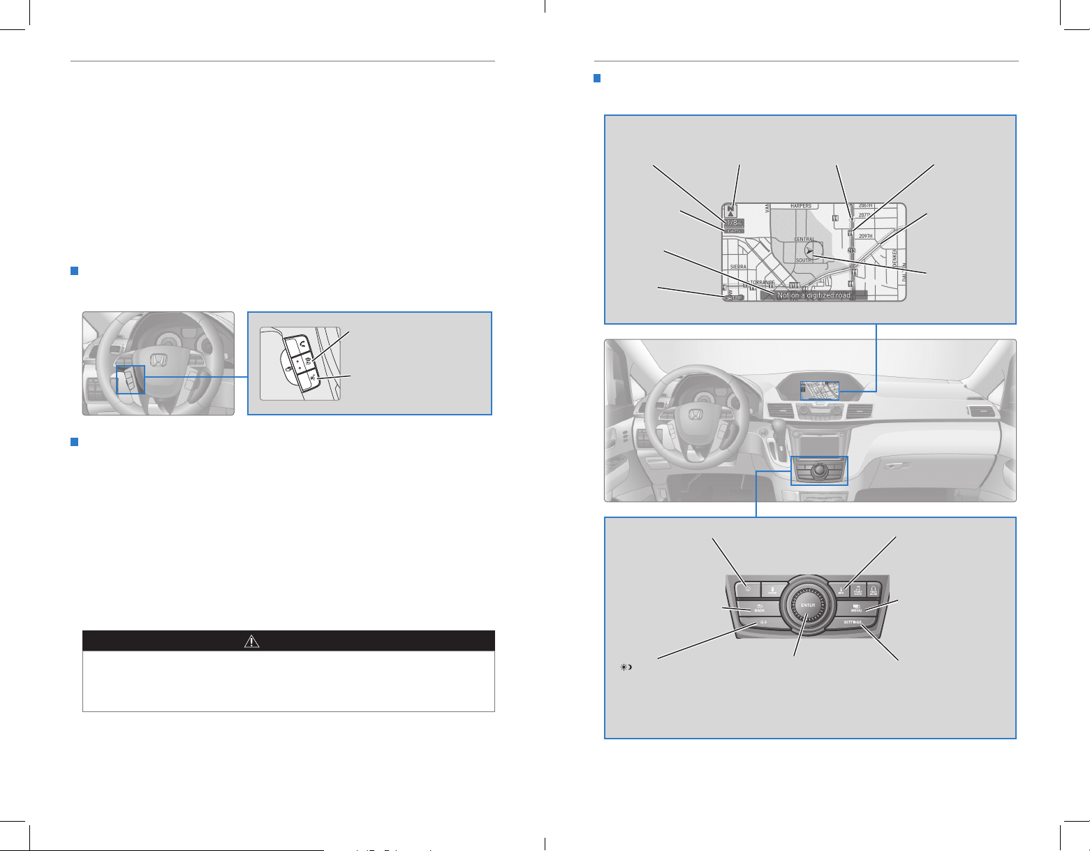
NAVIGATIONNAVIGATION
NAV
NAVIGATION*
Learn how to enter a destination and operate the navigation system.
Basic Navigation Operation
A real-time navigation system uses GPS and a map database to show your current
location and help guide you to a desired destination. You can operate the system
using voice commands or the system controls.
To reduce the potential for driver distraction, certain manual functions may be
inoperable or grayed out while the vehicle is moving. Voice commands are always
available.
Steering Wheel Controls
Use the steering wheel controls to give voice commands.
BACK button: Press to cancel
a command or operation.
TALK button: Press to give
navigation commands.
Voice Command Tips
• When using the Talk button, wait for a beep before saying a command.
• To bypass the system prompts, simply press the Talk button again to say your
command.
• When the Talk button is pressed, all available voice commands are highlighted
in yellow.
• Speak in a clear, natural voice.
• Reduce all background noise.
• Adjust the dashboard and side vents away from the microphone in the ceiling.
• Close the windows and moonroof.
WARNING
Using the navigation system while driving can take your attention away from
the road, causing a crash in which you could be seriously injured or killed.
Operate system controls only when the conditions permit you to safely do so.
Navigation Display and Controls
Use the controls to enter information and make selections.
Current
map scale
GPS signal
strength
Current
street
Traffic
status
NAV button: Display
the map screen or
directions when en
route.
BACK button: Go back
to the previous display.
button: Change screen
brightness. Use the
interface dial to make
adjustments.
Map
orientation
Interface dial (from the map
screen): Rotate to scroll the
map or menus. Move up,
down, left, or right. Press
ENTER to make a selection.
Traffic
incident icon
Landmark
icon
Traffic flow
Current vehicle
position
INFO button: Select
items such as calendar,
traffic incidents, and
more.
MENU button:
Enter destination
information.
SETTINGS button:
Change settings for
map and routing
options.
*if equipped
84 | | 85
Page 47
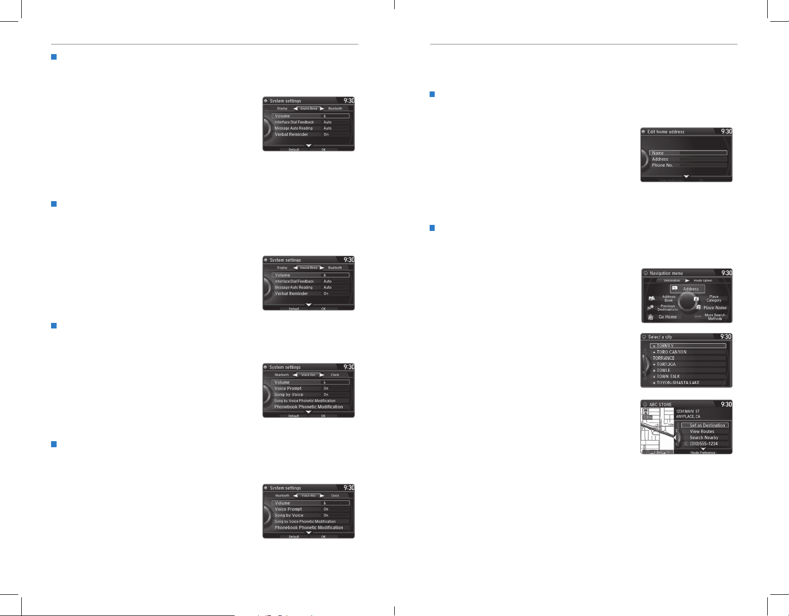
NAVIGATIONNAVIGATION
Interface Dial Feedback
Configure the system to read aloud selections made using the interface dial. Use
the interface dial to make and enter selections.
1. Press SETTINGS.
2. Select System Settings.
3. Select Interface Dial Feedback.
4. Select Off, Auto, or On.
ON: Always reads the selection.
AUTO: Reads the selection only when the vehicle is moving.
OFF: Turns interface dial feedback off.
System Guidance Volume
Adjust the navigation system volume. This does not affect audio or Bluetooth®
HandsFreeLink® volume, which is controlled by the volume knob. Use the interface
dial to make and enter selections.
1. Press SETTINGS.
2. Select System Settings.
3. Select Volume.
4. Adjust the level, or select off.
Voice Prompt
Turn the voice feedback feature on or off. Use the interface dial to make and enter
selections.
1. Press SETTINGS.
2. Select System Settings.
3. Select Voice Rec.
4. Select Voice Prompt.
5. Select On or Off.
Voice Prompt Volume
Adjust the voice prompt volume when they are turned on. Use the interface dial to
make and enter selections.
1. Press SETTINGS.
2. Select System Settings.
3. Select Voice Rec.
4. Select Volume.
5. Adjust the level, or select Off.
Entering a Destination
Use multiple methods to enter a destination.
Home Address
Store your home address in the system so you can easily route to it. Use the
interface dial to make and enter selections.
1. Press SETTINGS.
2. Select Navi Settings.
3. Select Edit Go Home.
4. Enter the address, and select OK when complete.
When your home address is stored, you can press the Talk button and say “Go
home” at any time. You can also select Go home from the destination menu.
Street Address
Enter a street address using voice commands. Press the Talk button before saying
each command.
1. Say “Address.”
2. Say “Street,” then say the street name on the
next screen. For Canadian vehicles, spell the
street name one letter at a time. Do not include
the direction (N, S, E, W) or type (St., Ave., Blvd.,
etc.).
3. A list of street names appears. Say the number
next to the street you want to select.
4. Say the entire street address number. For
example, “1-2-3-4.” If necessary, say “OK” to
proceed.
5. If the street address is in more than one city, a
list of city names appears. Say the number next
to the city you want to select.
6. Say “Set as destination” to set the route.
86 | | 87
Page 48
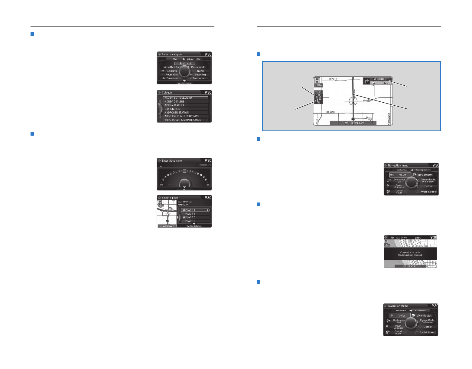
NAVIGATIONNAVIGATION
Place Category
Enter a destination using a point of interest or landmark using the interface dial.
1. Press MENU.
2. Select Place Category.
3. Select a category and a subcategory. For
example, Auto Service followed by Honda
Dealers.
4. Select a search method, such as Sort by
Distance to Travel.
5. A list of places appears. Scroll the list to select
the place you want.
6. Select Set as Destination to set the route.
Find Nearest Place
Enter a destination by category and distance using voice commands. Press the
Talk button before saying each command.
1. Say “Find nearest” and a place. For example,
“Find nearest ATM.”
2. A list of the nearest places in your area is
displayed by shortest distance to destination.
3. Say the number next to the destination you want
to select.
4. Say “Set as destination” to set the route.
Routing
After a destination is set, you can alter or cancel your route.
Map Legend
During route guidance
Estimated time
to destination
Distance to
destination
Taking a Detour
You can calculate a detour route manually if you encounter a road closure or other
obstacle. Use the interface dial to make and enter selections.
1. When en route, press DEST/ROUTE.
2. Select Detour. The system attempts to calculate
a new route by avoiding the next 5 miles (8 km)
while on a freeway or 1 mile (1 km) while on a
surface street.
FM Traffic
View traffic flow, incidents, and construction in major metro areas. You can also
route around congestion or incidents using voice commands. Press the Talk
button before saying each command.
Next
guidance
point
Calculated
route
1. When en route, say “Display trafc on my route.”
A list of incidents on your route appears.
2. Say the number of the incident you want to avoid.
3. Say “Avoid” and the incident list returns.
4. Say “Reroute” to set the new route.
Canceling Your Route
You can cancel your route at any time. Press the Talk button and say “Cancel
route.” You can also use the interface dial to make and enter selections.
1. When en route, press DEST/ROUTE.
2. Select Cancel Route. The route is cleared and the
map screen returns.
88 | | 89
Page 49
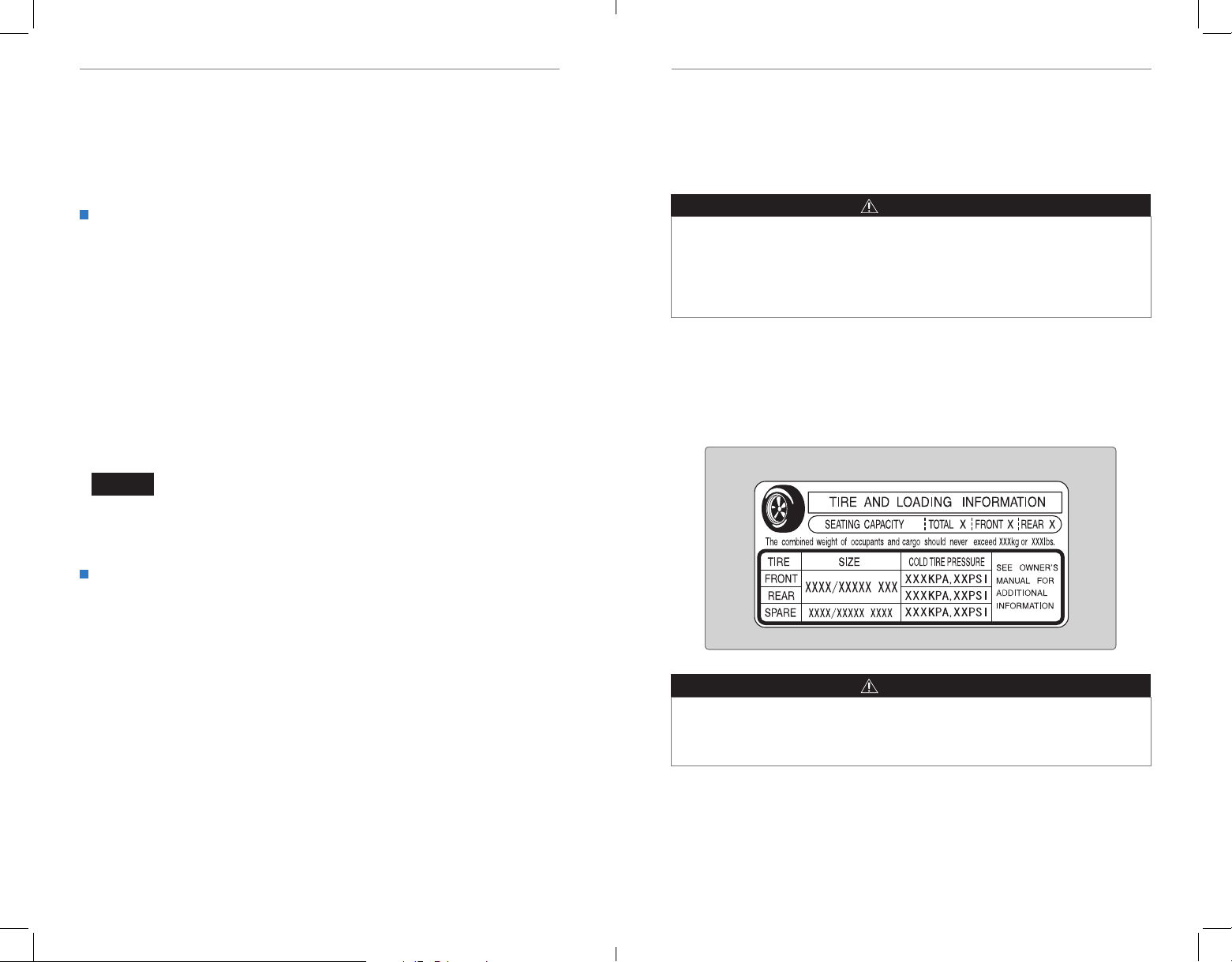
DRIVINGDRIVING
DRIVING
Learn about preparation for driving, as well as other features.
Before Driving
Check the following items before you begin driving.
Exterior Checks
• Make sure there are no obstructions on the windows, door mirrors, exterior
lights, or other parts of the vehicle.
• Remove any frost, snow, or ice.
• Make sure the hood is securely closed.
• Heat from the engine and exhaust can ignite ammable materials left under
the hood, causing a re. If you’ve parked your vehicle for an extended period,
inspect and remove any debris that may have collected, such as dried grass
and leaves that have fallen or have been carried in for use as a nest by a small
animal. Also check under the hood for leftover ammable materials after you or
someone else has performed maintenance on your vehicle.
• Make sure the tires are in good condition.
• Make sure there are no people or objects behind or around the vehicle.
NOTICE
If the doors are frozen shut, use warm water around the door edges to melt any
ice. Do not try to force them open, as this can damage the rubber trim around the
doors. When done, wipe dry to avoid further freezing.
In addition:
• During the rst 600 miles (1,000 km) of operation, avoid sudden acceleration or
full throttle operation so as to not damage the engine or powertrain.
• Avoid hard braking for the rst 200 miles (300 km). You should also follow this
when the brake pads are replaced.
WARNING
Improper accessories or modications can affect your vehicle’s handling, and
stability, and performance, and cause a crash in which you can be seriously hurt
or killed.
Follow all instructions in the vehicle owner’s manual regarding accessories and
modifications.
Maximum Load Limit
Carrying too much cargo or improperly storing it can affect your vehicle’s handling,
stability, stopping distance, and tires, and make it unsafe.
The maximum load for your vehicle is 1,340 lbs (608 kg). See the Tire and Loading
Information label on the driver’s doorjamb.
Label example
Interior Checks
• Store or secure all items on board properly.
• Do not pile items higher than the seat height.
• Do not place anything in the front seat footwells. Make sure to secure the oor
mats.
• If you have any animals on board, do not let them move freely around in the
vehicle.
• Securely close and lock all doors and the tailgate.
• Adjust your seating position, mirrors, and steering wheel properly.
• Make sure items placed on the oor behind the front seats cannot roll under the
seats.
• Everyone in the vehicle must fasten their seat belt.
• Make sure that the indicators in the instrument panel come on when you start
the vehicle, and go off soon after.
90 | | 91
Overloading or improper loading can affect handling and stability and cause a
crash in which you can be hurt or killed.
Follow all load limits and other loading guidelines in this guide.
The headlight aim on your vehicle was set by the factory, and does not need to be
adjusted. However, if you regularly carry heavy items in the cargo area or pull a
trailer, have the aiming readjusted at your dealer or by a qualied technician.
WARNING
Page 50
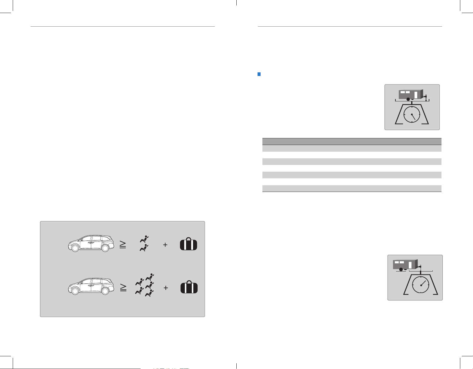
DRIVINGDRIVING
Load Limits Example
Example 1
Max load
1,340 lbs
(608 kg)
Passenger weight
150 lbs x 2 = 300 lbs
(68 kg x 2 = 136 kg)
Cargo weight
1,040 lbs
(472 kg)
Example 2
Max load
1,340 lbs
(608 kg)
Passenger weight
150 lbs x 5 = 750 lbs
(68 kg x 5 = 340 kg)
Cargo Weight
590 lbs
(268 kg)
Tongue Loa d
This figure includes the total weight of all occupants, cargo, and
accessories, and the tongue load if you are towing a trailer. Below are the
steps for determining the correct load limit:
1. Locate the statement “The combined weight of occupants and cargo
should never exceed XXX kg or XXX lbs.” on your vehicle’s placard.
2. Determine the combined weight of the driver and passengers that will be
riding in your vehicle.
3. Subtract the combined weight of the driver and passengers from XXX kg
or XXX lbs.
4. The resulting gure equals the available amount of cargo and luggage
load capacity. For example, if the “XXX” amount equals 1,400 lbs. and
there will be ve 150 lb. passengers in your vehicle, the amount of
available cargo and luggage load capacity is 650 lbs. (1,400 - 750 (5 x 150)
= 650 lbs.)
5. Determine the combined weight of luggage and cargo being loaded on
the vehicle. That weight may not safely exceed the available cargo and
luggage load capacity calculated in step 4.
6. If your vehicle will be towing a trailer, load from your trailer will be
transferred to your vehicle. Consult the Owner’s Manual on the Owner
Information CD or at owners.honda.com (U.S.) or myhonda.ca (Canada)
to determine how this reduces the available cargo and luggage load
capacity of your vehicle.
In addition, the total weight of the vehicle, all occupants, accessories,
cargo, and trailer tongue load must not exceed the Gross Vehicle Weight
Rating (GVWR) or the Gross Axle Weight Rating (GAWR). Both are on a label
on the driver’s doorjamb.
Towing a Trailer
Your vehicle can tow a trailer if you carefully observe the load limits, use the proper
equipment, and follow the towing guidelines. See the Owner’s Manual on the Owner
Information CD or at owners.honda.com (U.S.) or www.myhonda.ca (Canada) for
more information.
Towing Load Limits
Total trailer weight
Do not exceed the maximum allowable weight of
the trailer, cargo, and everything in or on it shown in
the table below. Towing loads in excess of this can
seriously affect vehicle handling and performance
and can damage the engine and drivetrain.
Total load
Number of occupants Equip with ATF cooler
2 3,500 lbs (1,587 kg)
3 3,350 lbs (1,520 kg)
4 3,200 lbs (1,451 kg)
5 3,050 lbs (1,383 kg)
6 2,900 lbs (1,315 kg)
7 1,450 lbs (658 kg)
8 Towing not recommended
Each weight limit is calculated based on the following conditions:
• Occupants ll seats from the front of the vehicle to the back
• Each occupant weighs 150 lbs (68 kg)
Any additional weight, cargo or accessories reduce the maximum trailer weight
and maximum tongue load.
92 | | 93
Tongue load
The weight of the tongue with a fully loaded trailer
on the hitch should be approximately 10% of the
total trailer weight.
• Excessive tongue load reduces front tire traction
and steering control. Too little tongue load can
make the trailer unstable and cause it to sway.
• To achieve a proper tongue load, start by loading
60% of the load toward the front of the trailer and
40% toward the rear. Readjust the load as needed.
Tongue load
Page 51
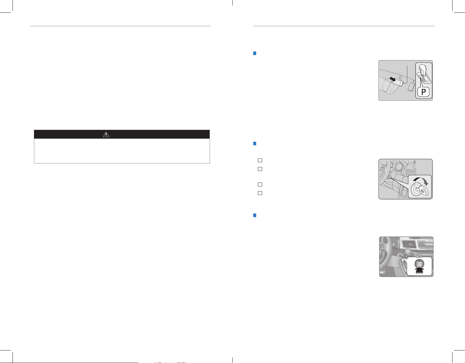
DRIVINGDRIVING
Pre-tow checklist
When preparing to tow, and before driving away, ensure the following:
• The vehicle has been properly serviced, and the suspension and the cooling
system are in good operating condition.
• Avoid towing a trailer during your vehicle’s rst 600 miles (1,000 km).
• The trailer has been properly serviced and is in good condition.
• All weights and loads are within limits. Never exceed the gross weight ratings.
• Check if all loads are within limits at a public scale. If a public scale is not
available, add the estimated weight of your cargo load to the weight of your
trailer (as quoted by the manufacturer) and the tongue load.
• The hitch, safety chains, and any other attachments are secure.
• All items in or on the trailer are properly secured and cannot shift while you drive.
WARNING
Exceeding any load limit or improperly loading your vehicle and trailer can
cause a crash in which you can be seriously hurt or killed.
Check the loading of your vehicle and trailer carefully before starting to drive.
Starting to Drive
Turn on the vehicle and start the engine to begin driving.
Before Starting the Engine
Check that the shift lever is in Park (P), then press the
brake pedal. Keep your foot rmly on the brake pedal
when starting the engine.
The engine is harder to start in cold weather and in thinner air found at altitudes
above 8,000 feet (2,400 m). When starting the engine in cold weather, turn off
all electrical accessories such as the lights, climate control system, and rear
defogger in order to reduce battery drain.
Starting the Ignition*
Insert the key into the ignition and turn to turn on the vehicle or start the engine.
0
LOCK: Insert and remove the key in this position.
I
ACCESSORY: Operate the audio system and other
accessories in this position.
II
ON: This is the position when driving.
III
START: This position is for starting the engine.
The switch returns to ON when you release the key.
Brake pedal
Changing the Power Mode*
Use the ENGINE START/STOP button to cycle through power modes or start the
engine.
Accessory or On mode: Press ENGINE START/STOP
once without pressing the brake pedal for Accessory
mode. Press it again for On mode.
Starting the engine: Press and hold the brake pedal,
then press ENGINE START/STOP. Keep your foot rmly
on the brake pedal when starting the engine.
Turning the vehicle off: Shift to Park (P), then press
ENGINE START/STOP.
If you press the button and the shift lever is not in Park
(P), the vehicle goes into Accessory mode.
*if equipped
94 | | 95
Page 52
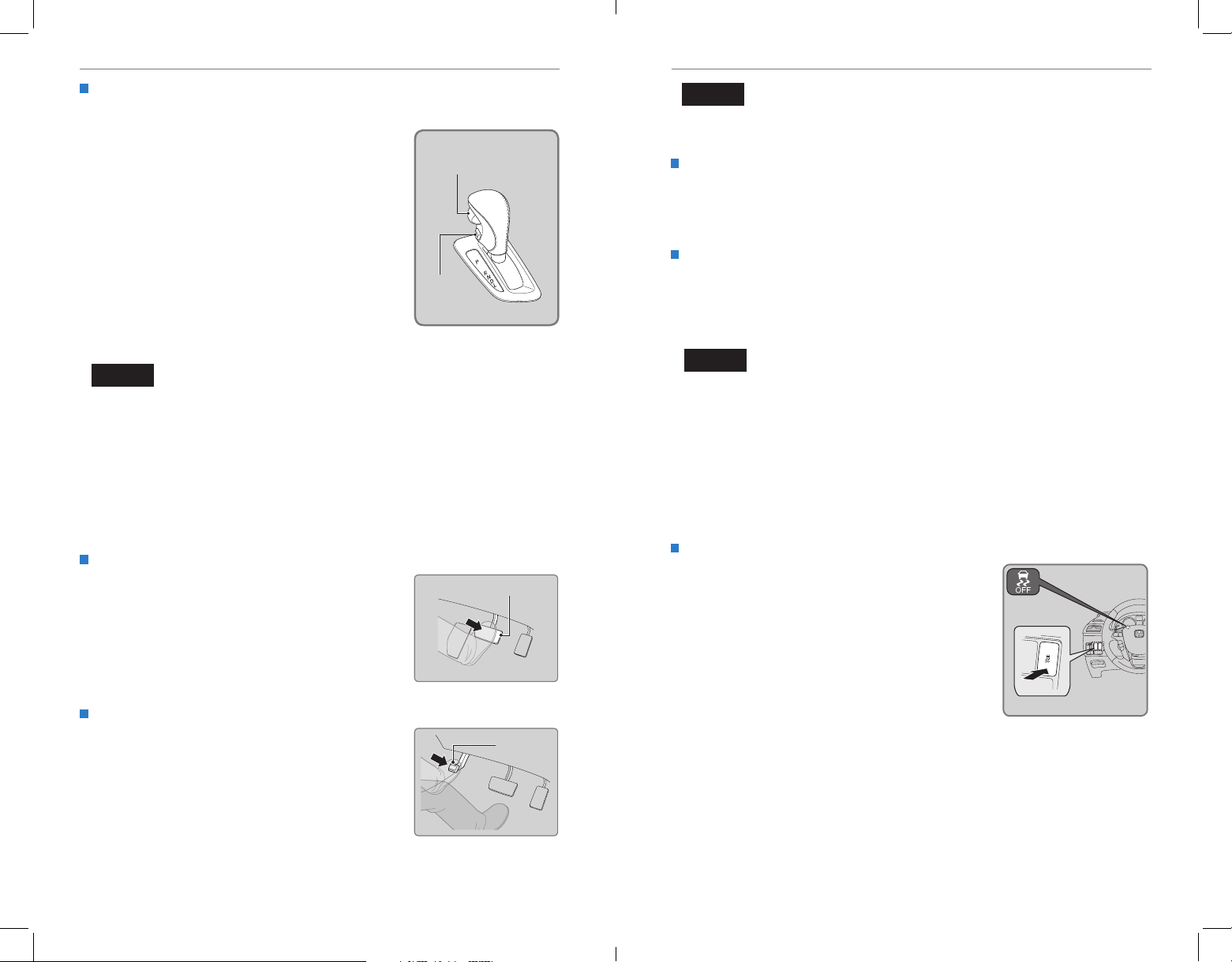
DRIVINGDRIVING
Shifting
Change the shift position based on your driving needs.
Park (P): Used for parking or starting/stopping the
engine. Press the brake pedal, then press the release
button to shift.
Release
button
Reverse (R): Used for reversing.
Neutral (N): Used for idling.
Drive (D): Used for normal driving.
D4: Press the D4 button when the shift lever is in
Drive. Used for going up or down hills or towing a
trailer in hilly terrain.
D4
button
Low (L): Used for stronger engine power and braking
when driving in hilly terrain.
NOTICE
When you change the shift lever from D to R and vice versa, come to a complete
stop and keep the brake pedal depressed. Operating the shift lever before the
vehicle has come to a complete standstill can damage the transmission.
Do not operate the shift lever while pressing the accelerator pedal. You could
damage the transmission.
Braking
Slow down or stop your vehicle, and keep it from moving when parked.
Foot Brake
Press the brake pedal to slow down or stop your
vehicle from moving.
Parking Brake
Keep the vehicle from moving when it is parked.
To apply: Press the parking brake with your foot.
To release: Press the brake pedal, then press the
parking brake until it releases.
Brake pedal
Parking
brake
NOTICE
Release the parking brake fully before driving. The rear brakes and axle can be
damaged if you drive with the parking brake applied.
Brake Assist System
During hard or emergency braking, the system increases braking force. The brake
pedal may move slightly or make a noise; this is normal. Continue to hold the brake
pedal firmly down.
Anti-Lock Brake System (ABS)
During hard or emergency braking, the system rapidly pumps the brakes to
prevent wheel lockup and help you maintain steering control. The brake pedal may
pulsate slightly during ABS operation; this is normal. Do not pump the brake pedal,
and continue to hold it firmly down.
NOTICE
The ABS may not function correctly if you use an incorrect tire type and size.
Vehicle Stability Assist (VSA®), aka Electronic Stability Control
(ESC) System
Helps to stabilize the vehicle during cornering if the vehicle turns more or less
than what was intended. It assists in maintaining traction on slippery surfaces by
regulating engine output and selectively applying the brakes.
Turning VSA On or Off
VSA is turned on every time you start the engine,
even if you previously turned it off. If you turn
VSA off, your vehicle has normal braking and
cornering ability, but not VSA traction and stability
enhancement.
Press and hold the VSA OFF button until you hear a
beep to turn VSA on or off. The VSA OFF indicator
appears when the system is off.
Traction control stops functioning, which may make
it easier when trying to free your vehicle if it is stuck
in mud or snow.
VSA OFF
indicator
VSA OFF button
96 | | 97
Page 53
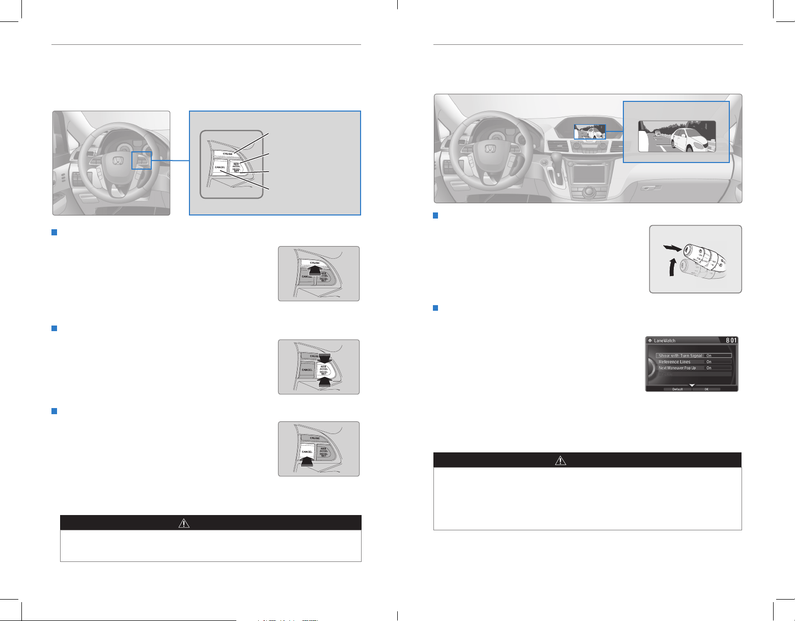
DRIVINGDRIVING
Cruise Control
Maintain a constant vehicle speed without having to keep your foot on the
accelerator pedal. Use cruise control on freeways or open roads where you can
travel at a constant speed with little acceleration or deceleration.
CRUISE button
RES/ACCEL button
DECEL/SET button
CANCEL button
Activating and Setting the Vehicle Speed
1. Press CRUISE. The CRUISE MAIN indicator
appears.
2. Accelerate to the desired speed (above 25 mph/
40 km/h). Press DECEL/SET and take your foot off
the pedal to set the speed. The CRUISE CONTROL
indicator appears.
Adjusting the Vehicle Speed
Press RES/ACCEL to increase or DECEL/SET to decrease.
Each time you press the button, the vehicle speed is
increased or decreased by about 1 mph (1.6 km/h). If you
keep the button pressed, the vehicle speed increases or
decreases until you release it.
Canceling Cruise Control
Press CANCEL or the brake pedal. The CRUISE CONTROL
indicator goes off.
After cruise control has been canceled, you can still
resume the prior set speed by pressing RES/ACCEL while
driving at a speed of at least 25 mph (40 km/h).
Press CRUISE to turn the system off.
WARNING
Improper use of the cruise control can lead to a crash.
Use cruise control only when traveling on open highways in good weather.
LaneWatch™*
Check the passenger-side rear areas in the upper display when the right turn signal
is activated.
LaneWatch display
Activating LaneWatch
Activate the right turn signal. The LaneWatch display
appears. Check the display for blind spots, and
visually confirm that it is safe to change lanes.
You can also press the LaneWatch button on the end
of the turn signal switch to view a constant real-time
display. Press it again to turn the display off.
Changing Settings
Customize the display and how and when the display appears.
1. Press SETTINGS.
2. Select Camera Settings.
3. Select LaneWatch.
4. Select an option and make the preferred changes.
5. Press BACK to exit the menu.
Important Safety Reminder
Like all assistance systems, LaneWatch has limitations. Over-reliance on the system
may result in a collision.
WARNING
Failure to visually conrm that it is safe to change lanes before doing so may
result in a crash and serious injury or death.
Do not rely only on LaneWatch while driving. Always look in your mirrors, to
either side of your vehicle, and behind you for other vehicles before changing
lanes.
*if equipped
98 | | 99
Page 54
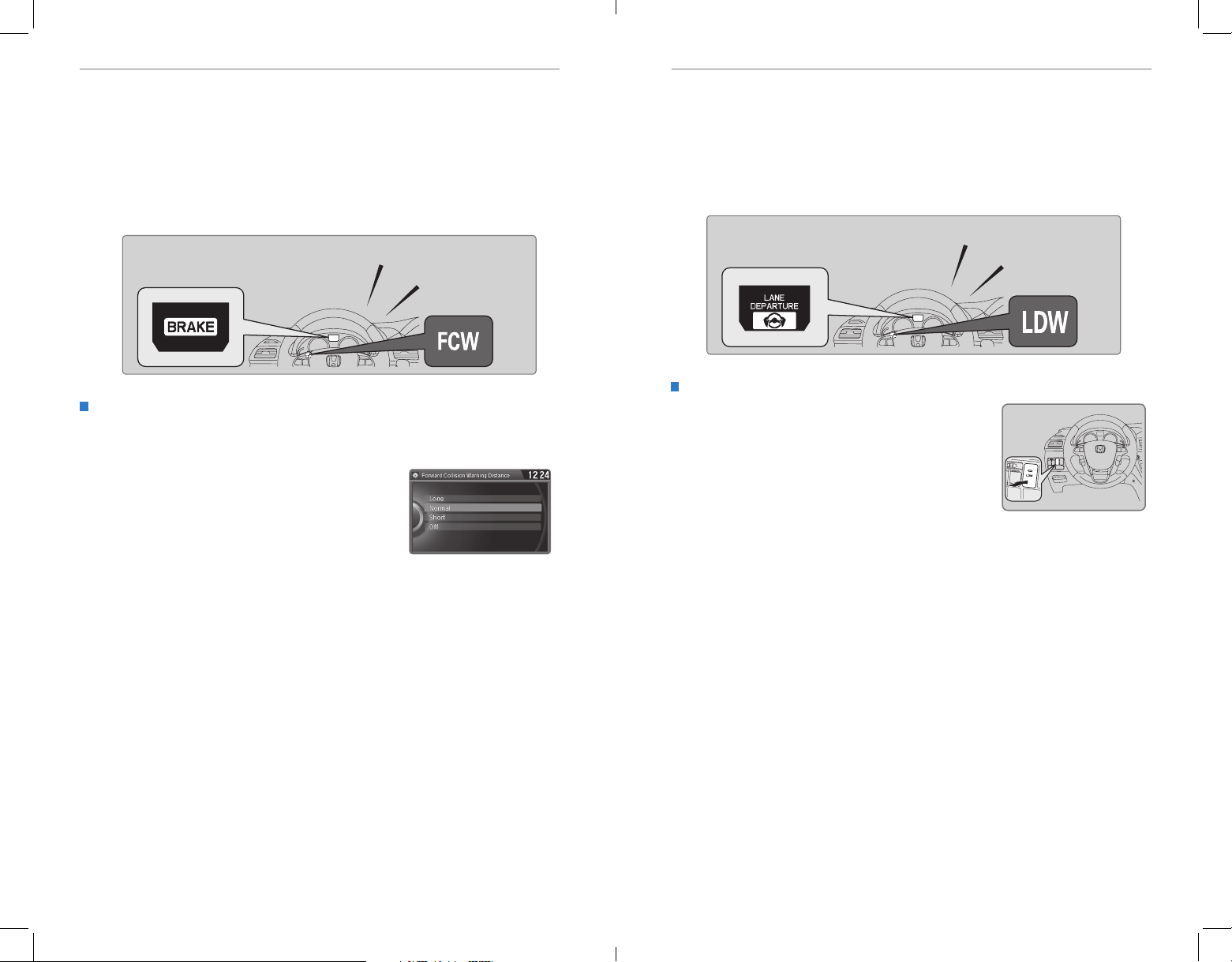
DRIVINGDRIVING
Forward Collision Warning (FCW)*
If the camera mounted between the windshield and the rearview mirror detects a
vehicle in front of you when your vehicle speed is 10 mph (15 km/h) or higher—and it
determines there is a likelihood of a frontal collision—the system provides you with
visual and audible warnings.
If you do not brake in time or take preventive action, BRAKE ashes in the display or
the FCW indicator blinks, and a beep sounds continuously.
BRAKE indicator
(models with multiinformation display)
Changing Settings
Determine the warning timing, or turn the system off. Use the interface dial to
make and enter selections.
1. Press SETTINGS.
2. Select Vehicle Settings. The vehicle must be in
Park (P).
3. Select Forward Collision Warning Distance.
4. Select Long, Normal, Short, or Off.
5. Press BACK to exit the menu.
Important Safety Reminder
FCW cannot detect all objects ahead and may not detect a given object; accuracy
of the system will vary based on weather, speed, extreme interior heat, and other
factors. FCW does not include a braking function. It is always your responsibility to
safely operate the vehicle and avoid collisions.
Beep
FCW indicator
(models with
information display)
Lane Departure Warning (LDW)*
A camera mounted between the windshield and the rearview mirror determines if
your vehicle begins to move away from the center of a detected lane while driving
between 40–90 mph (64–145 km/h).
If you cross a detected lane line without using your turn signal, a message appears
on the display or the LDW indicator blinks, and a beep sounds.
Lane departure indicator
(models with multiinformation display)
Turning LDW On or Off
Press LDW to turn the system on or off. A green
indicator light appears on the button when the system
is on.
Important Safety Reminder
Like all assistance systems, LDW has limitations. Over-reliance on LDW may result
in a collision. It is always your responsibility to keep the vehicle within your lane.
LDW only alerts you when lane drift is detected without a turn signal in use. LDW
may not detect all lane markings or lane departures; accuracy will vary based on
weather, speed, and lane marker condition. It is always your responsibility to safely
operate the vehicle and avoid collisions.
Beep
LDW indicator
(models with
information display)
LDW
button
*if equipped
100 | | 101
*if equipped
Page 55
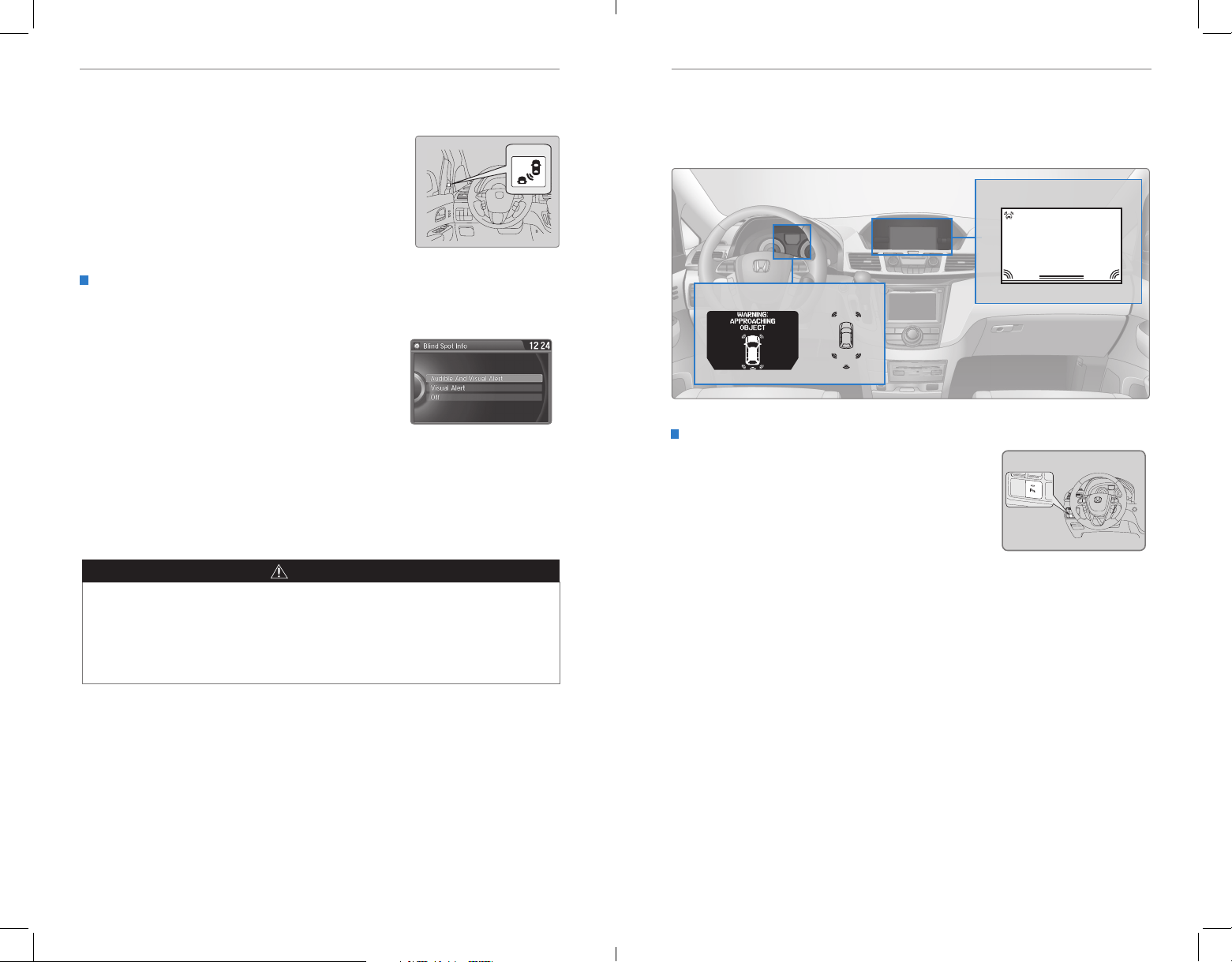
DRIVINGDRIVING
Blind Spot Information (BSI) System*
Alerts you to a detected vehicle in your left or right blind spot.
When a vehicle is detected in your blind spot, the
blind spot indicator turns on and stays lit until the area
is clear.
When your turn signal is on and a vehicle is detected,
the blind spot indicator blinks and a beep sounds until
the area is clear or the turn signal is off.
Changing BSI Settings
Determine the warning type, or turn the system off. Use the interface dial to make
and enter selections.
1. Press SETTINGS.
2. Select Vehicle Settings. The vehicle must be in
Park (P).
3. Select Driver Assist System Setup.
4. Select an alert type, or turn the system off.
5. Press BACK to exit the menu.
Important Safety Reminder
Like all assistance systems, BSI has limitations. Over-reliance on the system may
result in a collision. The system is for your convenience only.
Parking Sensor System*
When the system senses an object when you are parking or backing up, indicators
appear on the instrument panel and the navigation screen and a series of beeps will
sound. As you get closer to the object, the beep rate increases.
Screen indicators
Display and indicators
Turning the System On or Off
Press the parking sensor button. A green indicator
light appears on the button when the system is on.
Parking
sensor
button
WARNING
Failure to visually conrm that it is safe to change lanes before doing so may
result in a crash and serious injury or death. Do not rely only on the blind spot
information system when changing lanes.
Always look in your mirrors, to either side of your vehicle, and behind you for
other vehicles before changing lanes.
*if equipped
102 | | 103
*if equipped
Page 56
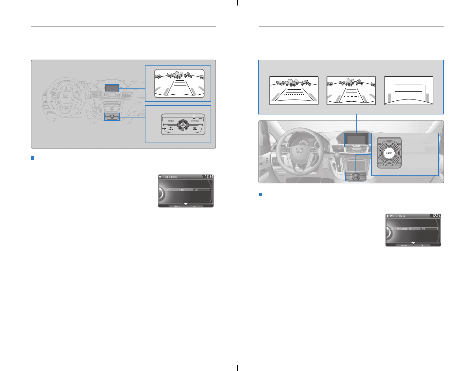
DRIVINGDRIVING
Rearview Camera*
When you shift into Reverse (R), a real-time image of the area behind your vehicle is
shown in the display, along with helpful parking guidelines.
SETTINGS button
BACK
button
Selector knob
Changing Camera Settings
Turn the guidelines on or off. Use the selector knob to make selections.
1. Press SETTINGS.
2. Select Camera Settings.
3. Select Rear Camera.
4. Select Fixed Guidelines.
5. Select On or Off.
6. Press BACK to exit the menu.
Multi-View Rear Camera*
When you shift into Reverse (R), a real-time image of the area behind your vehicle is
shown in the display, along with helpful parking guidelines.
Wide view Normal view Top down view
Press the
interface dial to
toggle between
views.
Changing Camera Settings
Turn the guidelines on or off. Use the interface dial to make and enter selections.
1. Press SETTINGS.
2. Select Camera Settings.
3. Select Fixed Guidelines.
4. Select On or Off.
5. Press BACK to exit the menu.
The rear camera view is restricted. You cannot see the corner ends of the bumper or what is
underneath the bumper. Its unique lens also makes objects appear closer or farther than they
actually are.
Visually conrm that it is safe to drive before backing up. Certain conditions (such as weather,
lighting, and high temperatures) may also restrict the rear view. Do not rely on the rearview display,
which does not give you all information about conditions at the rear of your vehicle.
*if equipped
104 | | 105
*if equipped
Page 57
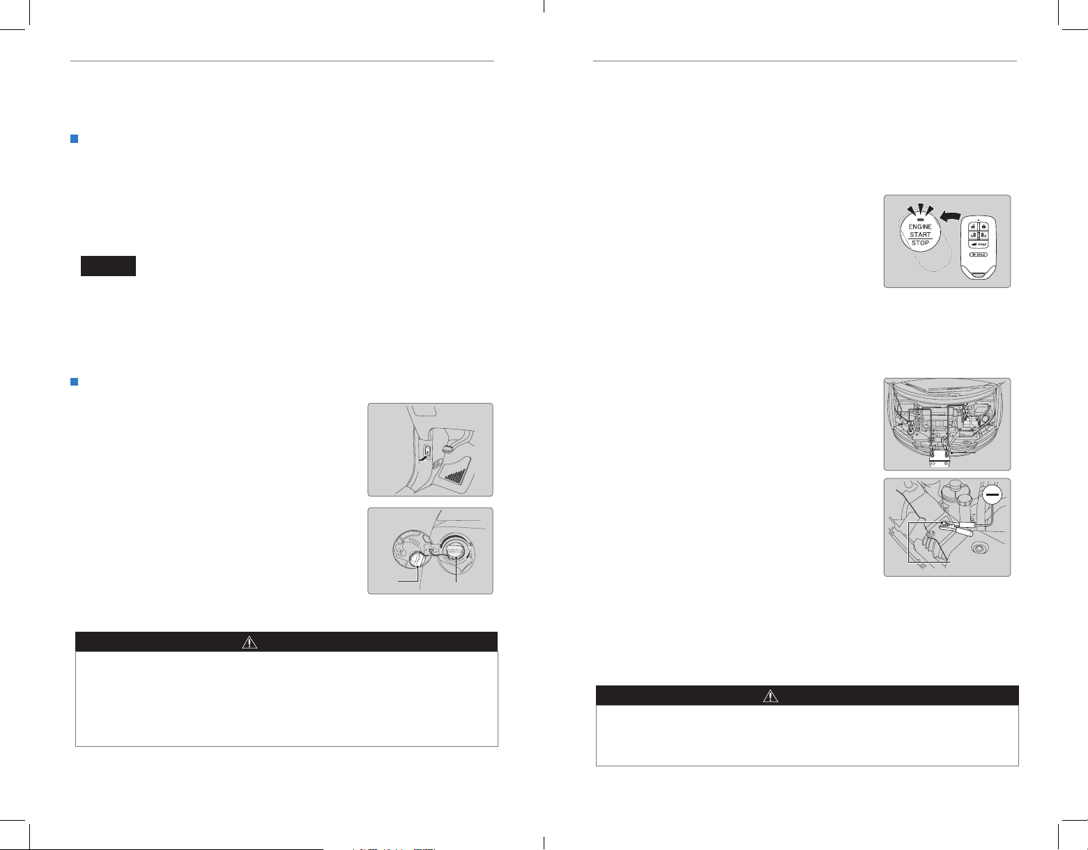
HANDLING THE UNEXPECTEDDRIVING
Refueling
Use the proper fuel and refueling procedure to ensure the best performance and
safety of your vehicle.
Fuel Information
Use of unleaded gasoline of 87 octane or higher is recommended.
• Honda recommends TOP TIER Detergent Gasoline where available.
• Do NOT use gasoline containing more than 15% ethanol.
• Do NOT use gasoline containing methanol.
• Do NOT use gasoline containing MMT.
NOTICE
We recommend quality gasoline containing detergent additives that help
prevent fuel system and engine deposits. In addition, in order to maintain good
performance, fuel economy, and emissions control, we strongly recommend the
use of gasoline that does NOT contain harmful manganese-based fuel additives
such as MMT, if such gasoline is available.
How to Refuel
1. The fuel fill door is located at the left rear of the
vehicle. Park next to the service pump that is
most accessible.
2. Turn off the engine.
3. Pull the fuel fill door release handle near the
parking brake. The fuel ll door opens.
4. Turn the fuel fill cap slowly to open. Place the fuel
fill cap in the holder.
5. Insert the ller nozzle fully. When the tank is full,
the fuel nozzle clicks off automatically.
6. Replace the fuel fill cap. Tighten it until you hear
at least one click. Close the fuel fill door.
Holder
Pull
Cap
WARNING
Gasoline is highly ammable and explosive. You can be burned or seriously
injured when handling fuel.
• Stop the engine, and keep heat, sparks, and flame away.
• Handle fuel only outdoors.
• Wipe up spills immediately.
HANDLING THE UNEXPECTED
Learn about what to do in critical or emergency situations.
Smart Entry Remote Battery Strength
If the battery life in your remote transmitter is weak, a message appears in the
display with information on how to start the engine.
1. Touch the back of the remote transmitter to the
ENGINE START/STOP button while the indicator is
flashing.
2. With the brake pedal pressed, press the ENGINE
START/STOP button within 10 seconds.
Jump Starting
Turn off the power to electric devices, such as audio and lights. Turn off the engine,
then open the hood.
1. Connect the rst jumper cable to your vehicle’s
battery (+) terminal.
2. Connect the other end of the rst jumper cable
to the booster battery (+) terminal. Use a 12-volt
booster battery only.
3. Connect the second jumper cable to the booster
battery (-) terminal.
4. Connect the other end of the second jumper cable
to the grounding point as shown. Do not connect
this jumper cable to any other part.
5. If your vehicle is connected to another vehicle,
start the assisting vehicle’s engine and increase its
rpm slightly.
6. Attempt to start your vehicle’s engine. If it turns
over slowly, make sure that the jumper cables have
good metal-to-metal contact.
WARNING: Battery posts, terminals, and related accessories contain lead and lead
compounds. Wash your hands after handling.
WARNING
A battery can explode if you do not follow the correct procedure, seriously
injuring anyone nearby.
Keep all sparks, open ames, and smoking materials away from the battery.
Booster
battery
Grounding
point
106 | | 107
Page 58
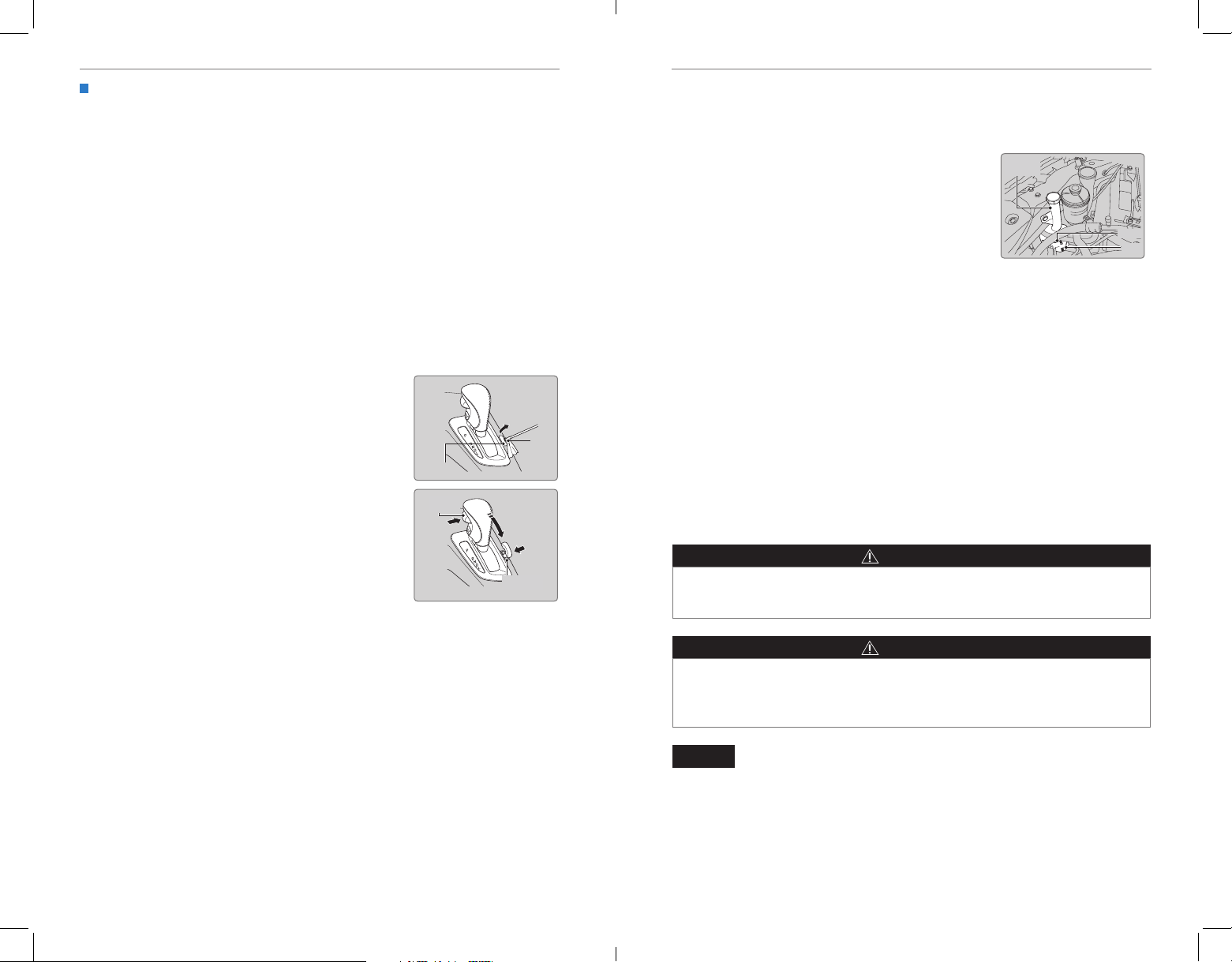
HANDLING THE UNEXPECTEDHANDLING THE UNEXPECTED
After the Engine Starts
Once your vehicle’s engine has started, remove the jumper cables in the following
order:
1. Disconnect the jumper cable from your engine hanger.
2. Disconnect the other end of the jumper cable from the assisting vehicle’s (-)
terminal.
3. Disconnect the jumper cable from your vehicle’s (+) terminal.
4. Disconnect the other end of the jumper cable from the assisting vehicle’s (+)
terminal.
5. Have your vehicle inspected by a nearby service station or a dealer.
Shift Lever Does Not Move
Follow the procedure below if you cannot move the shift lever out of Park (P).
1. Set the parking brake.
2. Remove the key from the ignition, or remove the
built-in key from the remote transmitter.
3. Wrap a cloth around the tip of a small flat-tip
screwdriver to remove the cover of the shift lock
release slot. Put the tip of the flat-tip screwdriver
into the slot and remove it as shown in the image.
4. Insert the key into the shift lock release slot.
5. While pushing the key down, press the shift lever
release button and place the shift lever into Neutral
(N). The lock is now released. Have the shift lever
checked by a dealer as soon as possible.
Cover
Release
button
Shift lock
release slot
Slot
Overheating
If the temperature gauge needle is at the H mark, the engine suddenly loses power,
or steam or spray comes out from under the hood, your engine is overheating.
1. Immediately park the vehicle in a safe place. Turn
off all accessories and turn on the hazard warning
Reserve
tank
lights.
2. If steam or spray is not present: Keep the engine
running and open the hood.
If steam or spray is present: Turn off the engine and
MAX
MIN
wait until it subsides. Then, open the hood.
3. Check that the cooling fan is operating and stop the engine once the temperature
gauge needle comes down. If the cooling fan is not operating, immediately stop
the engine.
4. Once the engine has cooled down, inspect the coolant level and check the
cooling system components for leaks. If the coolant level in the reserve tank
is low, add coolant until it reaches the MAX mark. If there is no coolant in the
reserve tank, make sure the radiator is cool, then cover the radiator cap with a
heavy cloth and open the cap. If necessary, add coolant up to the base of the
ller neck, and put the cap back on.
Once the engine has cooled sufficiently, restart it and check the temperature gauge.
If the temperature needle has gone down, resume driving. If it has not gone down,
contact a dealer for repairs.
WARNING
Steam and spray from an overheated engine can seriously scald you.
Do not open the hood if steam is coming out.
WARNING
Removing the radiator cap while the engine is hot can cause the coolant to
spray out, seriously scalding you.
Always let the engine and radiator cool down before removing the radiator cap.
NOTICE
Continuing to drive with the temperature gauge needle at the H mark may damage
the engine.
108 | | 109
Page 59
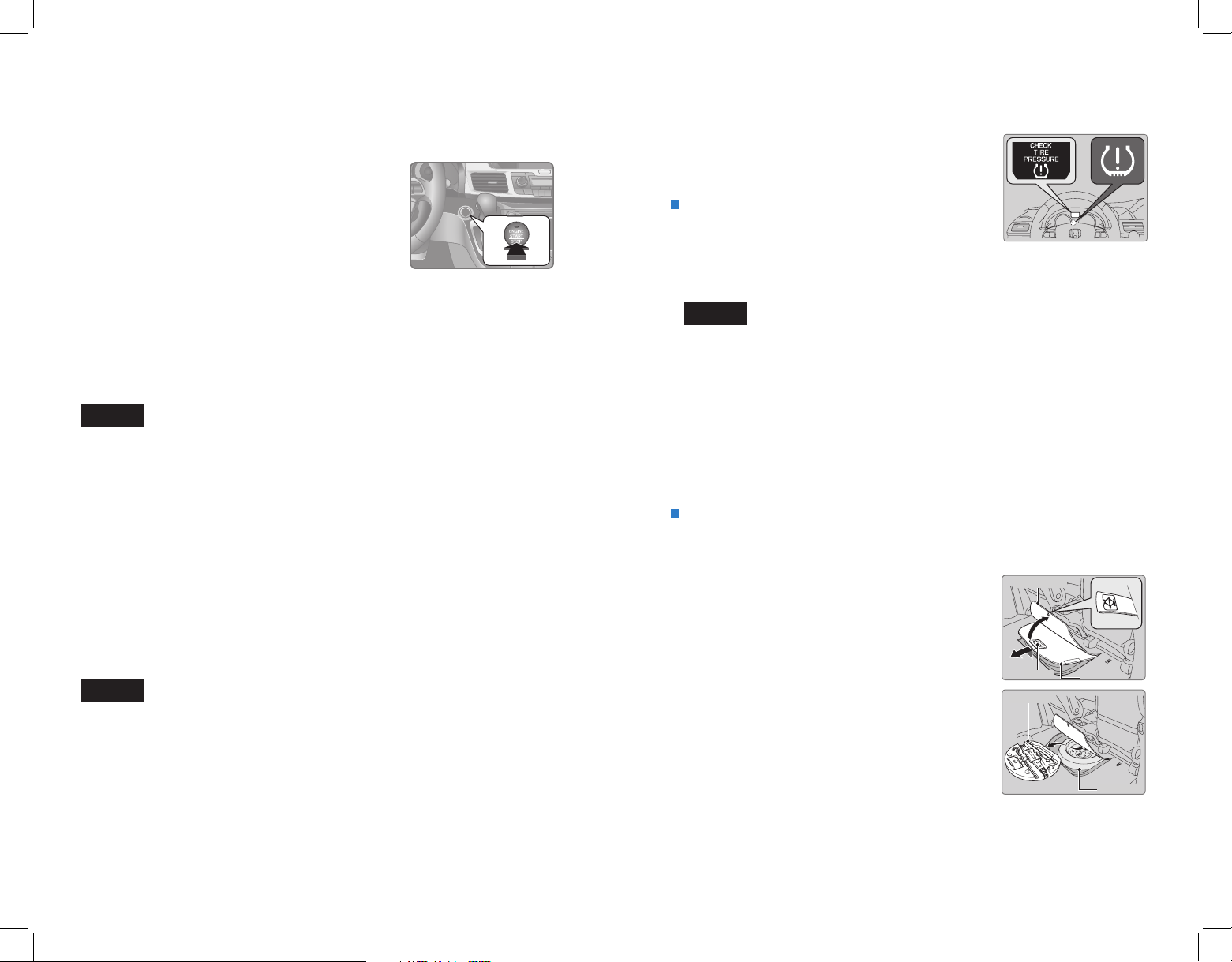
HANDLING THE UNEXPECTEDHANDLING THE UNEXPECTED
Emergency Engine Stop*
The ENGINE START/STOP button may be used to stop the engine due to an
emergency situation even while driving. If you must stop the engine, choose one of
the following operations:
• Press and hold the ENGINE START/STOP button for
two seconds, or
• Firmly press the ENGINE START/STOP button two
times.
The steering wheel will not lock. The power mode changes to ACCESSORY, unless
the shift lever is in Park (P), in which case the power mode changes to VEHICLE OFF.
Because turning off the engine also disables the power assist the engine provides
to the steering and braking systems, it will require signicantly more physical effort
and time to steer and slow the vehicle. Downshift gears and use both feet on the
brake pedal, if necessary, to slow the vehicle and stop immediately in a safe place.
NOTICE
Do not press the button while driving unless it is absolutely necessary for the engine
to be switched off.
Emergency Towing
Call a professional towing service if you need to tow your vehicle.
Flat bed equipment: The operator loads your vehicle on the back of a truck. This is
the best way to transport your vehicle.
Wheel lift equipment: The tow truck uses two pivoting arms that go under the front
tires and lift them off the ground. The rear tires remain on the ground. This is an
acceptable way to tow your vehicle.
NOTICE
Trying to lift or tow your vehicle by the bumpers will cause serious damage. The
bumpers are not designed to support the vehicle’s weight.
Improper towing such as towing behind a motorhome or other motor vehicle can
damage the transmission.
Tire Pressure Monitoring System (TPMS)
Monitors the tire pressure while you are driving.
If your vehicle’s tire pressure becomes signicantly low,
the low tire pressure indicator comes on and a message
appears on the multi-information display.
What to Do
Stop your vehicle in a safe place. Check the tire
pressure and adjust the pressure to the specified
level. The specied tire pressure is on a label on the
driver’s doorjamb.
NOTICE
Driving on an extremely underinated tire can cause it to overheat. An overheated
tire can fail. Always inflate your tires to the specified pressure.
Changing a Flat Tire
If a tire goes at while driving, grasp the steering wheel rmly, and brake gradually
to reduce speed. Then, stop in a safe place. Replace the flat tire with the compact
spare tire. Go to a dealer as soon as possible to have the full-size tire repaired or
replaced.
Getting Ready to Change the Tire
Park the vehicle on a rm, level, non-slippery surface. Apply the parking brake,
shift to Park (P), and turn the vehicle off. Turn on the hazard warning lights.
1. Open the tailgate. Turn on the cargo lights if
necessary (see page 39). Remove the floor mat
under the second-row seat.
2. Pull up the floor carpet.
3. Lift up the floor lid using the handle and remove it.
4. Take the tool case out of the spare tire well. Take
the jack and wheel nut wrench out of the tool
case.
Floor carpet
Handle
Tool case
Floor lid
Spare tire
*if equipped
110 | | 111
Page 60
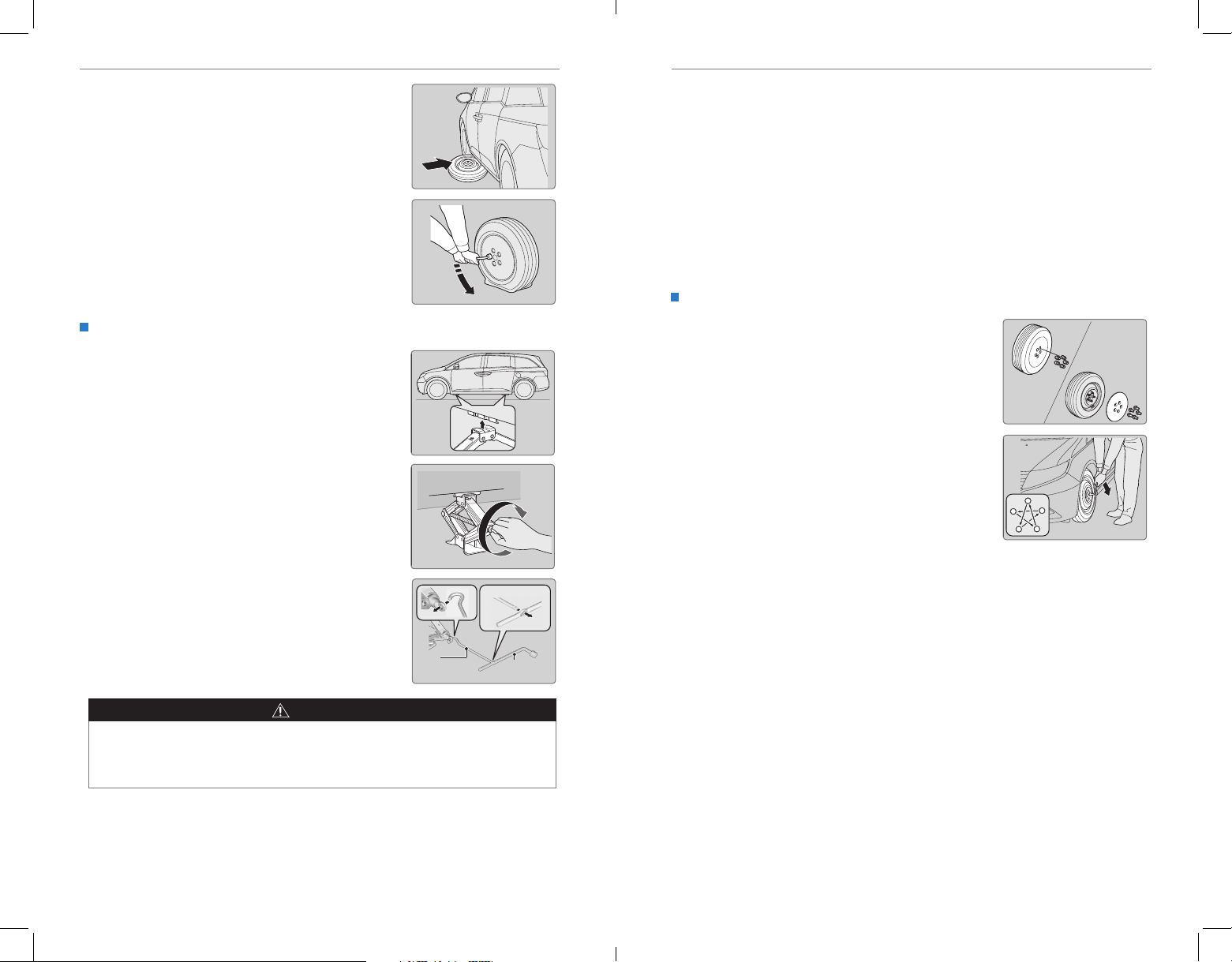
HANDLING THE UNEXPECTEDHANDLING THE UNEXPECTED
5. Unscrew the wing bolt, then remove the spare
tire.
6. Place a wheel block or rock in front and rear of
the wheel diagonal to the flat tire.
7. Place the compact spare tire (wheel side up)
under the vehicle body, near the tire that needs
to be replaced.
8. Loosen each wheel nut about one turn using the
wheel nut wrench.
Setting Up the Jack
1. Place the jack under the jacking point closest to
the tire to be changed.
2. Turn the end bracket (as shown in the image)
clockwise until the top of the jack contacts the
jacking point. Make sure that the jacking point
tab is resting in the jack notch.
The following instructions must be followed to use the jack safely:
• Do not use the jack with people or luggage in the vehicle.
• Use the jack provided in your vehicle. Other jacks may not support the weight
(“load”) or fit the jacking point.
• Do not use while the engine is running.
• Use only where the ground is firm and level.
• Use only at the jacking points.
• Do not get in the vehicle while using the jack.
• Do not put anything on top of or underneath the jack.
Replacing the Flat Tire
1. Remove the wheel nuts, wheel cover (if
necessary), and flat tire.
2. Mount the compact spare tire. Replace the
wheel nuts, and lightly tighten them.
3. Lower the vehicle and remove the jack. Tighten
the wheel nuts in the order indicated in the
image. Go around, tightening the nuts, two to
three times in this order. Do not overtighten the
wheel nuts.
If you drive with the spare tire installed, the
low tire pressure/TPMS indicator appears. The
indicator stays on until a regular tire is installed.
3. Raise the vehicle, using the jack handle bar and
the jack handle, until the tire is off the ground.
Jack
handle
bar
Wrench as jack handle
Wheel nut
WARNING
The vehicle can easily roll off the jack, seriously injuring anyone underneath.
Follow the directions for changing a tire exactly, and never get under the
vehicle when it is supported only by the jack.
112 | | 113
Page 61
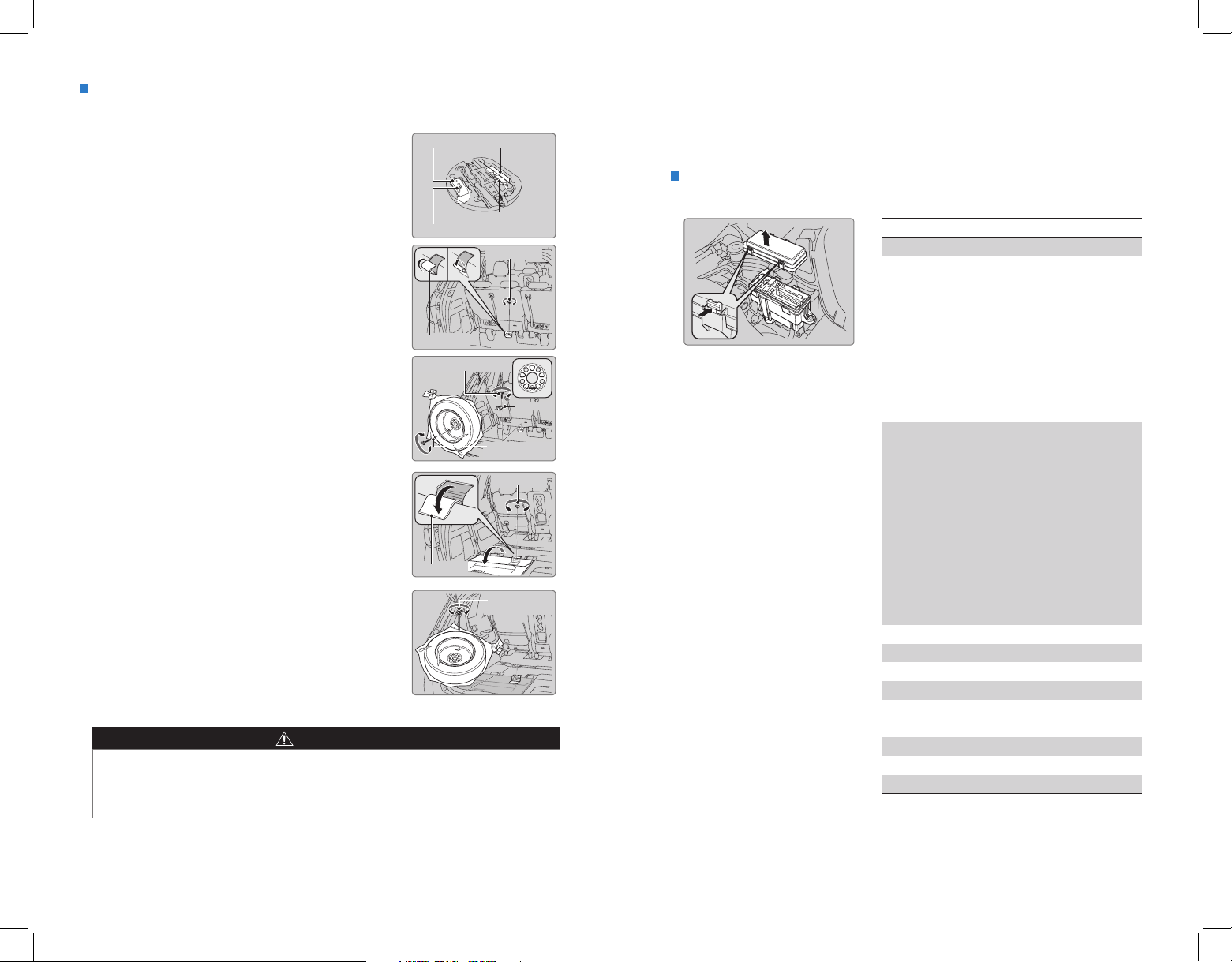
HANDLING THE UNEXPECTEDHANDLING THE UNEXPECTED
Circuit Protected Amps
*1
*2: Models with smart entry system
Storing the Flat Tire
The storage bag, bracket, and mounting wing bolts (A and B) are in the tool case.
1. Put the at tire in the storage bag provided with
Bracket
Storage bag
your vehicle.
2. Pull down the U-shaped carpet piece, fold it, and
tuck the end under the carpet.
Mounting wing bolt (B)
3. Remove the plastic screw with a coin.
Mounting wing bolt (A)
4. Install the bracket and the mounting wing bolt (A)
on the attachment point, and tighten the bolt.
5. Install the at tire on the bracket with the inside
of the wheel facing toward you.
6. Install the mounting wing bolt (B) to the bracket
through one of the five wheel nut holes, and
Mounting wing bolt (A)
tighten the bolt. Poke a hole in the storage bag as
needed.
Storing a flat tire on the folded third–row seat
1. Turn over the flap on the left side of the cargo
area floor.
2. Pull down the U-shaped carpet piece and remove
the plastic screw with a coin.
Carpet piece
3. Place the flat tire face down on the attachment
point.
4. Put the tire mounting wing bolt (B) in the
attachment point through one of the five wheel
nut holes, and tighten the bolt. Poke a hole in the
storage bag as needed.
WARNING
Loose items can fly around the interior in a crash and can seriously injure the
occupants.
Store the wheel, jack, and tools securely before driving.
Plastic screw
Bracket
Mounting wing
bolt (B)
Plastic screw
Mounting wing
bolt (B)
Fuse Locations
If any electrical devices are not working, turn the vehicle off and check to see if any
applicable fuse is blown. Fuse locations are shown on the fuse box cover. Locate the
fuse in question by the fuse number and box cover number.
Engine Compartment Fuse Box - Driver Side
Located under the hood near the battery. Push the tabs to open the box.
1 Main Fuse 125A
2-1
2-2
Passenger Side Fuse Box 2
2-3
2-4
2-5
2-6
2-7
2-8
3-1
3-2
3-2
3-3
3-4
Passenger Side Fuse Box 1 50 A
3-5
Engine Compartment Fuse
3-6
Box (Passenger Side) Main
3-7
3-8
4
5
6IG Main 2
7 IG Main 1
8
9 Stop & Horn 20 A
11 Interior Lights 7.5 A
: Models without smart entry system
Fan Main 60 A
50 A
HondaVAC
Interior Light, FI Main
Stop & Horn, Hazard
Rear Blower, Battery
Management System
TM*
(60 A)
30 A
30 A
30 A
VSA FSR 30 A
VSA Motor
40 A
Driver Side Fuse Box 2 50 A
IG1 Main
Starter Motor
*1
*2
50 A
40 A
Rear Fuse Box 1 60 A
Driver Side Fuse Box 1 50 A
60 A
Passenger’s Side Power
Sliding Door Motor
(40A)
*
Front Blower 40 A
Rear Defroster
40 A
− −
*
*
Battery Management
System
30 A
30 A
7.5 A
15 A10 Hazard
114 | | 115
*if equipped
Page 62
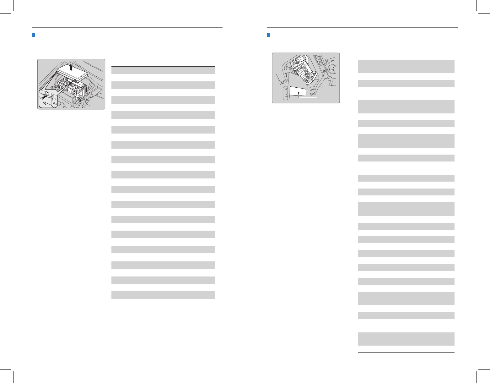
HANDLING THE UNEXPECTEDHANDLING THE UNEXPECTED
Circuit Protected Amps
r1
b1
−−
−−
x1
−−
−−
Engine Compartment Fuse Box - Passenger Side
Located under the hood near the windshield washer reservoir. Push the tabs to
Interior Fuse Box - Driver Side
Located under the dashboard.
open the box.
Circuit Protected Amps
Front Passenger's Door
1 − −
2− −
3 ACG FR 15 A
4Washe
5 A
5 VB SOL 7.5 A
6ECU FR 7.5 A
7 − −
8FI Su
5A
9 DBW 15 A
10 FI Main 15 A
11 Ignition Coil 15 A
12
13 − −
14
15 Radio 20 A
16 Back Up 10 A
17 MG Clutch 7.5A
18 Front Fog Lights
*
(20 A)
19 − −
20 Right Headlight High Beam 10 A
21 − −
22 Small Lights 10 A
23 − −
24 Left Headlight High Beam 10 A
25 − −
26 Right Headlight Low Beam 15 A
27 Left Headlight Low Beam 15 A
28 Oil Level 7.5 A
29 Main Fan 30 A
30 Sub Fan 30 A
31 Wiper Main 30 A
Fuse label
1
2 Rear Passenger's Door Lock 7.5A
3 Driver’s Door Lock 7.5A
Front Passenger's Door
4
Rear Passenger's Door
5
6 Driver’s Door Unlock 7.5A
7 Door Lock Main 20 A
8 HAC Option
Driver’s Side Power Sliding
9
10 Rear Fuse Bo
11 Meter 7.5 A
Engine Compartment Fuse
12
13 Accessory 7.5A
14 STS
15 Driver’s Power Seat Sliding 20 A
16 Moonroof
Rear Driver’s Side Power
17
18 Smart Entry System
19 Driver’s Power Window 20 A
20
21 Fuel Pump 20 A
22 Passenger Side Fuse Box15 A
23 VSA 7.5A
24 ACG AS 7.5 A
25 STRLD 7.5A
26 HAC 7.5 A
27 DRL (7.5 A)
28 ACC Key Lock 7.5A
Driver’s Power Seat Lumbar
29
Lock
Unlock
Unlock
*
Door Closer
*
Box (Passenger Side)
*
*
Window
*
Support
*
30 TPMS 7.5A
31 − −
32
33
*if equipped
116 | | 117
*if equipped
34
Driver’s Power Seat
Reclining
Driver’s Side Power Sliding
Door Motor
*
7.5 A
7.5A
7.5A
(20A)
7.5 A
(20 A)
(10 A)
(7.5 A)
(40A)
10 A
5 A
20 A
20 A
20 A
Page 63
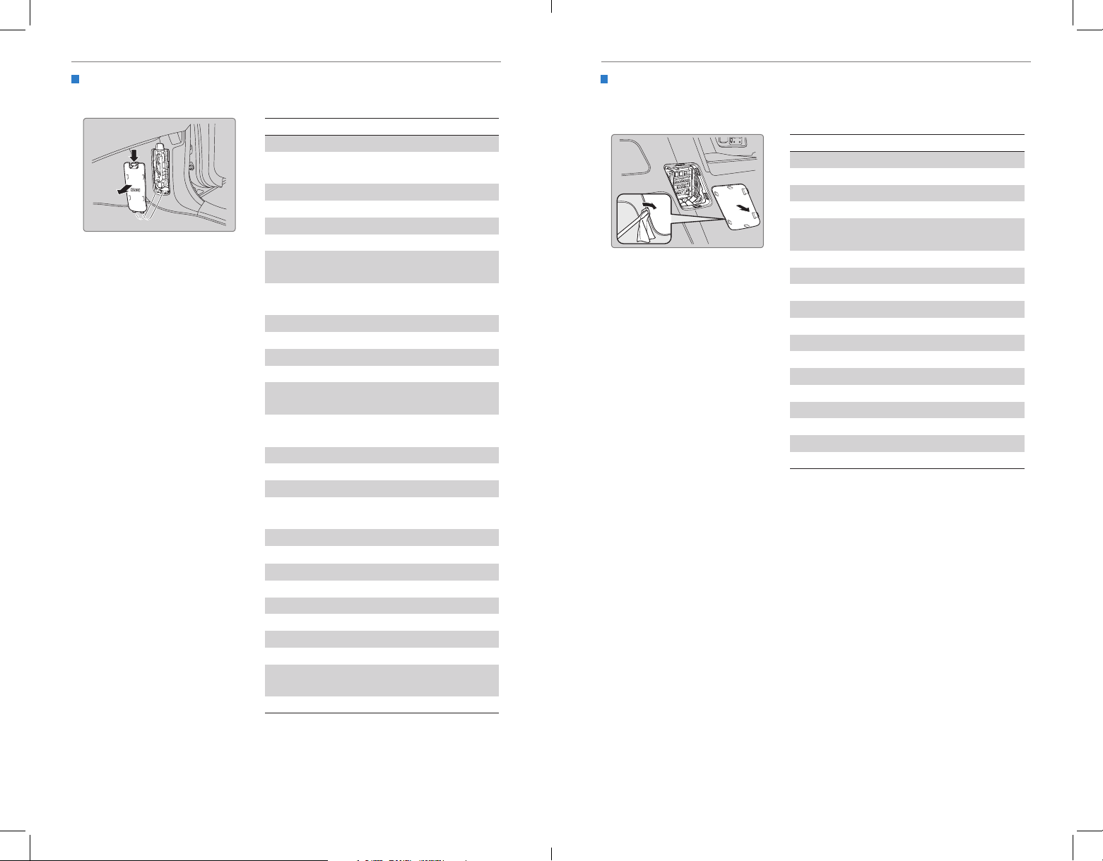
HANDLING THE UNEXPECTEDHANDLING THE UNEXPECTED
Circuit Protected Amps
−−
−−
−−
−−
−−
−−
−−
−−
Interior Fuse Box - Passenger Side
Located on the lower side panel. Take off the cover to open.
1 Premium Amp
Rear Passenger’s Side
2
3 ACM 10 A
4
5 Seat Heaters
6 − −
Front Passenger’s Power
7
Front Passenger’s Power
8
9 − −
10
11 − −
12
Passenger’s Side Power
13
14
Sliding Door Closer
Rear Accessory Power
15 − −
16
17 − −
Front Passenger’s Power
18
19 SRS 10 A
20 ECU AS 7.5 A
21 Headlight Adjuster
22
23 OPDS
24 OPDS
25 Illumination (Interior) 7.5A
26
Front Accessory Power
27
28
Power Window
−
Seat Sliding
Seat Reclining
Socket
Window
*
*
Socket
Rear Fuse Box
Located on the left side of the cargo area. Remove the cover by prying on the edge
with a cloth-wrapped flat-tip screwdriver.
*
(30 A)
20 A
1 Power Tailgate Closer
2 Trailer Small Light
Circuit Protected Amps
*
(20 A)
*
(7.5 A)
3 − −
*
(15A)
(20 A)
(20 A)
−
4
Rear Driver’s Side Door
5
6 − −
7 − −
8 Trailer
9 Trailer Charge
10 Trailer Back Light
11 Trailer Hazard
Tailgate
Lock
*
(10 A)
7.5A
*
*
*
*
(10 A)
(20 A)
(7.5 A)
(7.5 A)
12 Rear Wiper 10 A
13 ECU RR 7.5A
(20A)
*
15 A
14 Power Tailgate Motor
15 AC Inverter
16
*
*
(40 A)
(30A)
17 − −
18
20 A
*
(7.5 A)
(7.5 A)
(7.5 A)
15 A
*if equipped
118 | | 119
*if equipped
Page 64
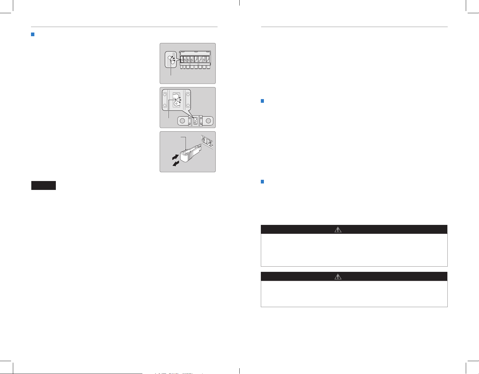
MAINTENANCEHANDLING THE UNEXPECTED
Inspecting and Changing Fuses
1. Turn the vehicle off, including all lights and
accessories.
2. Remove the fuse box cover.
Blown fuse
3. Check the large fuse in the engine compartment.
If the fuse is blown, use a Phillips-head
screwdriver to remove the screws and replace
the fuse with a new one. Reinstall the screws.
4. Inspect the small fuses in the engine
compartment and the vehicle interior.
If there is a burned out fuse, remove it with the
fuse puller and replace it with a new one.
NOTICE
Replacing a fuse with one that has a higher rating greatly increases the chances
of damaging the electrical system.
Blown
fuse
Fuse puller
MAINTENANCE
Learn about basic maintenance that you can perform on the vehicle yourself, as well
as information about how to best maintain the vehicle.
Safety Precautions
Some of the most important safety precautions are listed below; however, we cannot
warn you of every conceivable hazard that can arise in performing maintenance.
Only you can decide whether or not you should perform a given task.
Maintenance Safety
• To reduce the possibility of re or explosion, keep cigarettes, sparks, and ames
away from the battery and all fuel-related parts.
• Never leave rags, towels, or other ammable objects under the hood.
• To clean parts, use a commercially available degreaser or parts cleaner, not
gasoline.
• Wear eye protection and protective clothing when working with the battery or
compressed air.
• Do not run the engine in conned spaces where carbon monoxide gas can
accumulate.
Vehicle Safety
• The vehicle must be stationary, and parked on level ground with the parking
brake set and the engine off.
• Be aware that hot parts can burn you.
• Be aware that moving parts can injure you.
WARNING
Improperly maintaining this vehicle or failing to correct a problem before driving
can cause a crash in which you can be seriously hurt or killed.
Always follow the inspection and maintenance recommendations according to
the schedules in this guide.
WARNING
Failure to properly follow maintenance instructions and precautions can cause
you to be seriously hurt or killed.
Always follow the procedures and precautions in this guide.
120 | | 121
Page 65
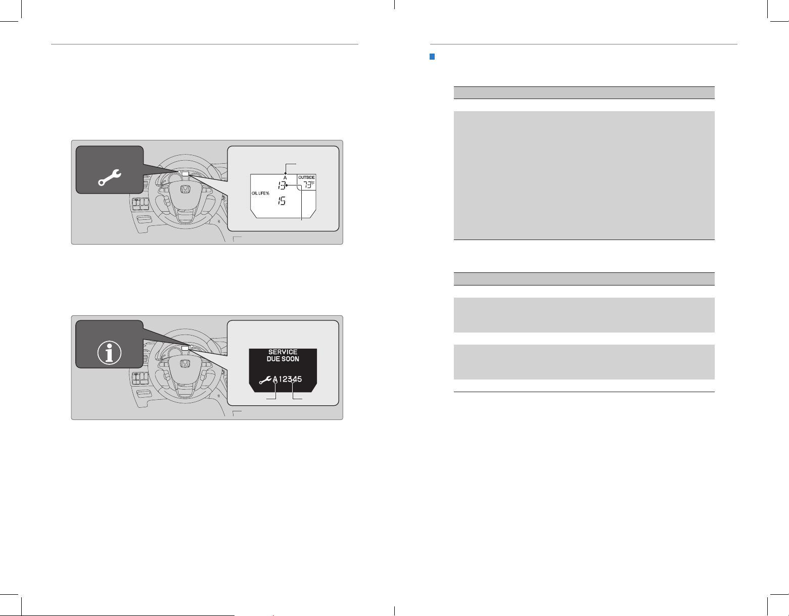
MAINTENANCEMAINTENANCE
CODE Maintenance Main Items
If you drive in dusty conditions, replace the air cleaner element every 15,000 miles (24,000 km).
Maintenance Minder™
Reminds you when indicated maintenance service is due.
Models with information display
When maintenance is due, the Maintenance Minder indicator comes on and a
message appears on the display every time you turn the vehicle on. Press the select/
reset knob to change displays.
Maintenance
Minder indicator
Models with multi-information display
When maintenance is due, the system message indicator comes on and a message
appears on the display every time you turn the vehicle on. Press the Info button on
the steering wheel to change displays.
Maintenance
Minder indicator
• Independent of the Maintenance Minder information, replace the brake uid
every 3 years.
• Inspect idle speed every 160,000 miles (256,000 km).
• Adjust the valves during services A, B, 1, 2, or 3 if they are noisy.
Maintenance Minder message
Main items
Sub items
Maintenance Minder message
Main items Sub items
Maintenance Minder Service Codes
These codes indicate what services are due on your vehicle.
•
A Replace engine oil
•
B Replace engine oil*1 and oil filter
•
Inspect front and rear brakes
•
Check parking brake adjustment
•
Inspect tie rod ends, steering gearbox, boots, and
*1
drain plug
•
Inspect suspension components
•
Inspect driveshaft boots
•
Inspect brake hoses and lines (including ABS/VSA)
•
Inspect all fluid levels and condition of fluids
•
Inspect exhaust system
•
Inspect fuel lines and connections
*1: If a message SERVICE does not appear more than 12 months after the display is reset,
change the engine oil every year.
#: See information on maintenance and emissions warranty.
#
#
CODE Maintenance Sub Items
1 Rotate tires•
2 Replace air cleaner element
•
Replace dust and pollen filter
•
Inspect drive belt
•
3 Replace transmission fluid
•
•
4 Replace spark plugs
•
Replace timing belt and inspect water pump
•
Inspect valve clearance
•
5 Replace engine coolant
*2:
*3: If you drive primarily in urban areas that have high concentrations of industrial soot and
pollution from diesel-powered vehicles, replace the dust and pollen filter every 15,000 miles
(24,000 km).
*4: If you drive regularly in very high temperatures (over 110°F, 43°C), in very low temperatures
(under -20°F, -29°C), replace every 60,000 miles/100,000 km.
*2
*3
*4
U.S. Models
Maintenance, replacement, or repair of emissions control devices and systems
may be done by any automotive repair establishment or individuals using parts
that are certified to EPA standards.
According to state and federal regulations, failure to perform maintenance on the
maintenance main items marked with # will not void your emissions warranties.
However, all maintenance services should be performed in accordance with the
intervals indicated by the multi-information display.
122 | | 123
Page 66
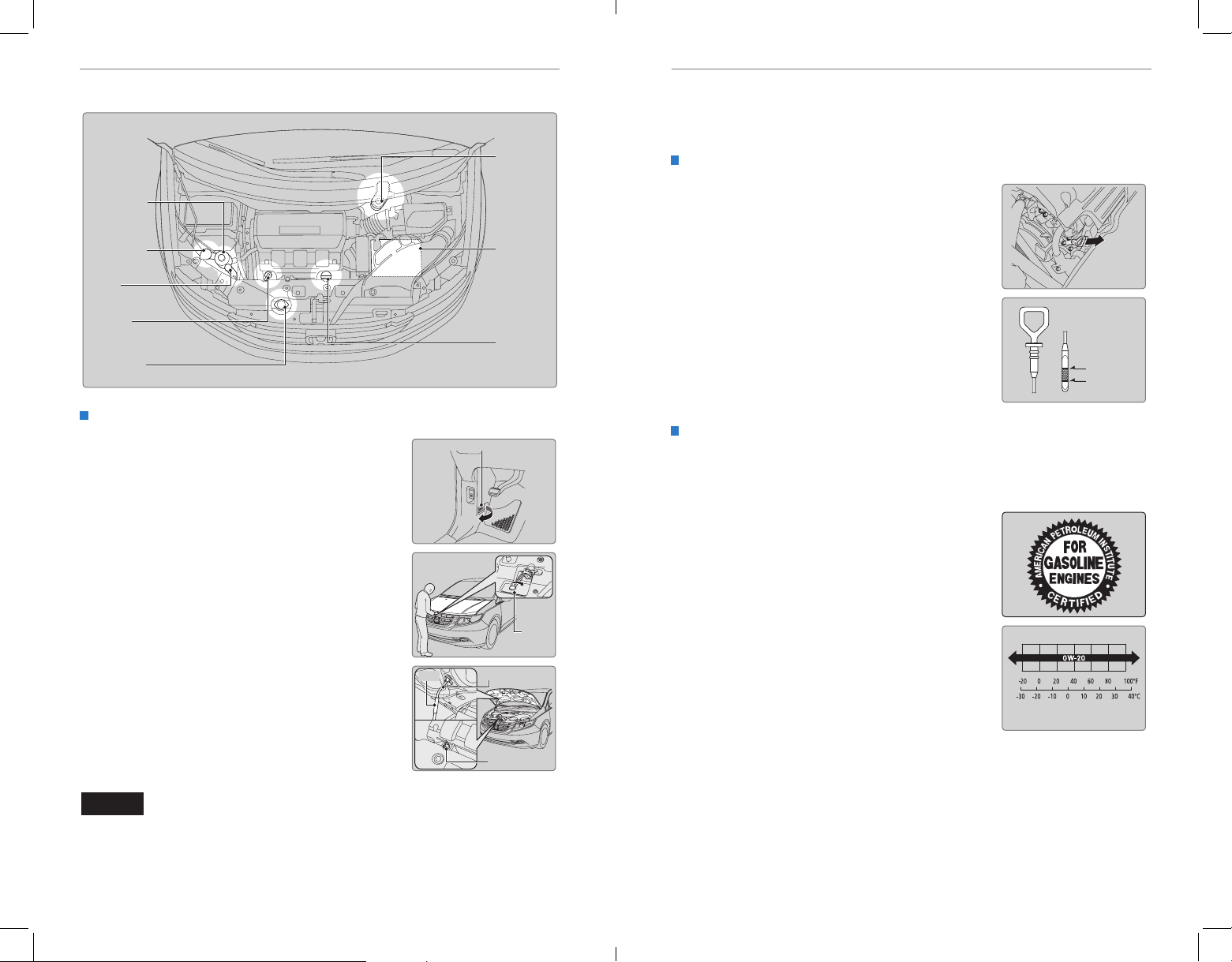
MAINTENANCEMAINTENANCE
Under the Hood
Power
steering fluid
(red cap)
Washer fluid
(blue cap)
Engine
coolant
reservoir
Engine oil
dipstick
(orange loop)
Radiator cap
Opening the Hood
1. Park the vehicle on a level surface, and set the
parking brake.
2. Pull the hood release handle under the lower left
corner of the dashboard.
3. Push up the hood latch lever in the center of the
hood to release the lock mechanism, and open
the hood.
Brake fluid
(black cap)
Battery
Engine oil
fill cap
Hood release handle
Pull
Engine Oil
Park the vehicle on level ground, and wait approximately three minutes after turning
the engine off before you check the oil.
Checking the Oil
1. Remove the dipstick (orange loop).
2. Wipe the dipstick with a clean cloth or paper
towel.
3. Insert the dipstick back all the way into its hole.
4. Remove the dipstick again, and check the level.
It should be between the upper and lower marks.
Add oil if necessary.
Recommended Engine Oil
• Honda Genuine Motor Oil
• Premium-grade 0W-20 detergent oil with an API Certification Seal on the
container
This seal indicates the oil is energy conserving and
that it meets the American Petroleum Institute’s
latest requirements.
Upper mark
Lower mark
4. Remove the support rod from the clamp using the
grip. Mount the support rod in the hood.
When closing, remove the support rod, and
stow it in the clamp, then gently lower the hood.
Grip
Lever
Support rod
Use Honda Genuine Motor Oil or another
commercial engine oil of suitable viscosity for the
ambient temperature as shown.
Ambient temperature
Remove your hand at a height of approximately
12 inches (30 cm) and let the hood close.
Clamp
You may also use synthetic motor oil if it is labeled with the API Certication Seal
and is of the specified viscosity grade.
NOTICE
Do not open the hood when the wiper arms are raised. The hood will strike the
wipers, and may damage either the hood or the wipers.
124 | | 125
Page 67
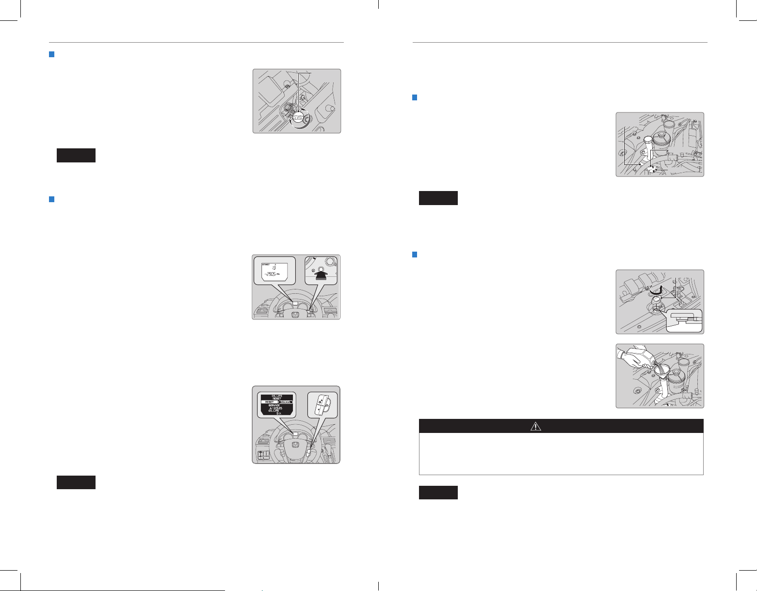
MAINTENANCEMAINTENANCE
Adding Oil
1. Unscrew and remove the engine oil fill cap.
2. Add oil slowly.
Engine oil
fill cap
3. Reinstall the engine oil fill cap, and tighten it
securely.
4. Wait for three minutes and recheck the engine oil
dipstick.
NOTICE
Do not ll the engine oil above the upper mark. Overlling the engine oil can result
in leaks and engine damage.
Resetting the Engine Oil Life
If you change or replace the vehicle’s engine oil yourself, you must reset the
engine oil life.
Models with information display
1. Press and hold the select/reset knob for 10
seconds or more. The reset mode appears in the
display.
2. Using the select/reset knob, select oil life.
3. Press and hold the select/reset knob for a few
seconds to enter the oil life reset mode.
4. Press and hold the select/reset knob for 5
seconds or more. The engine oil life display
returns to 100%.
Models with multi-information display
1. Press SEL/RESET to display the engine oil life.
From this screen, press and hold SEL/RESET for
10 seconds or more. The reset mode appears
in the display.
2. Press the Info button to select RESET. Press
SEL/RESET to select it. The engine oil life
display returns to 100%.
Engine Coolant
Park the vehicle on level ground. Check the reserve tank and the coolant level in the
radiator. We recommend Honda Long Life Antifreeze/Coolant Type 2.
Checking the Reserve Tank
1. Check the amount of coolant in the reserve tank.
Reserve
tank
2. If the coolant level is below the MIN mark, add
the specified coolant until it reaches the MAX
mark.
3. Inspect the cooling system for leaks.
MAX
MIN
NOTICE
If temperatures consistently below −22°F (−30°C) are expected, the coolant
mixture should be changed to a higher concentration. Consult a dealer for details
for more information.
Adding Coolant
1. Make sure the engine and radiator are cool.
Radiator cap
2. Turn the radiator cap counterclockwise and
relieve any pressure in the coolant system. Do
not push the cap down when turning.
3. Push down and turn the radiator cap
counterclockwise to remove it.
4. The coolant level should be up to the base of the
filler neck. Add coolant if it is low.
5. Put the radiator cap back on, and tighten it fully.
6. Pour coolant into the reserve tank until it reaches
the MAX mark. Put the cap back on the reserve
tank.
WARNING
Removing the radiator cap while the engine is hot can cause the coolant to spray
out, seriously scalding you.
Always let the engine and radiator cool down before removing the radiator cap.
NOTICE
Failure to reset the engine oil life after a maintenance service results in the system
showing incorrect maintenance intervals, which can lead to serious mechanical
problems.
126 | | 127
NOTICE
Pour the fluid slowly and carefully so you do not spill any. Clean up any spills
immediately; they can damage components in the engine compartment.
Page 68
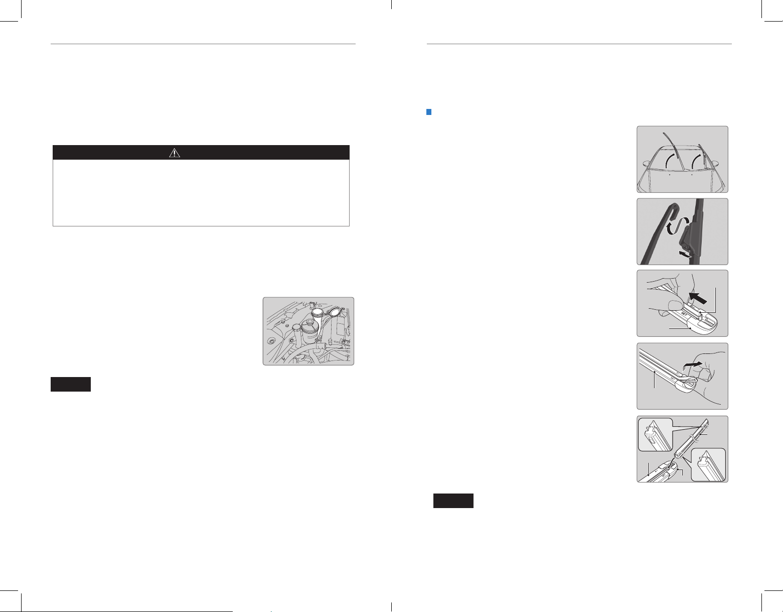
MAINTENANCEMAINTENANCE
Checking the Battery
The battery condition is monitored by the sensor on the negative terminal. If there is
a problem with the sensor, a message appears on the information display. Have your
vehicle checked by a dealer.
Check the battery terminals for corrosion monthly.
For jump starting, see page 107.
WARNING
The battery gives off explosive hydrogen gas during normal operation.
A spark or ame can cause the battery to explode with enough force to kill or
seriously hurt you.
When conducting any battery maintenance, wear protective clothing and a
face shield, or have a skilled technician do it.
WARNING: Battery posts, terminals, and related accessories contain lead and lead
compounds. Wash your hands after handling.
Window Washer Fluid
If the washer uid level is low, ll the washer reservoir.
Canadian models
If the washer uid level is low, the washer level
indicator or a message appears.
Changing Wiper Blades
If the wiper blades leave streaks across the windshield, try cleaning them rst with a
paper towel or soft cloth and wiper uid. If the wiper blade rubber has deteriorated,
you should change the wiper blades.
Changing the Front Wiper Blade Rubber
1. Lift the driver side wiper arm first, then the
passenger side.
2. Press and hold the tab, then slide the blade from
the wiper arm.
3. Pull the end of the wiper blade to the direction
of the arrow (as shown in the image) until it
unfastens from the holder’s end cap.
Tab
4. Pull the wiper blade to the opposite direction to
slide it out from its holder.
5. Insert the at side of the new wiper blade onto
the bottom part of the holder. Insert the blade all
the way.
6. Install the end of the wiper blade into the cap.
End cap at
the bottom
Wiper
blade
NOTICE
Do not use engine antifreeze or a vinegar/water solution in the windshield washer
7. Slide the wiper blade onto the wiper arm until it
locks
Holder
reservoir. Antifreeze can damage your vehicle’s paint. A vinegar/water solution can
damage the windshield washer pump.
8. Lower the passenger side wiper arm first, then
the driver side.
Holder
Cap
Wiper
blade
NOTICE
Avoid dropping the wiper arm, as it may damage the windshield.
128 | | 129
Page 69
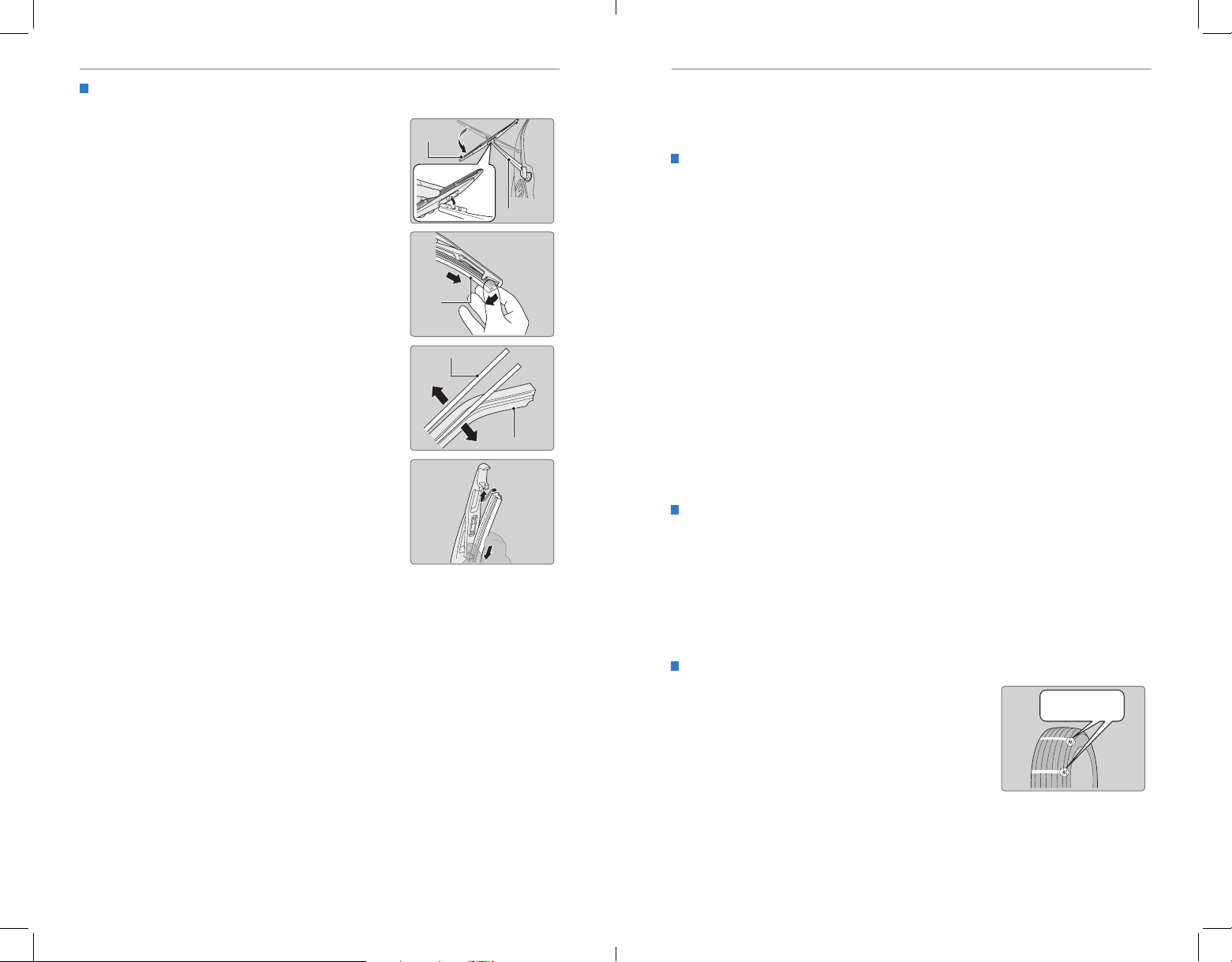
MAINTENANCEMAINTENANCE
Example of a wear
indicator mark
Changing the Rear Wiper Blade Rubber
1. Raise the wiper arm off.
2. Pivot the bottom end of the wiper blade up until it
comes off from the wiper arm.
3. Slide the blade out of the wiper.
4. Remove the retainers from wiper blade and
mount it to a new rubber blade.
5. Slide the new wiper blade onto the holder. Make
sure it is engaged correctly, then install the wiper
blade assembly onto the wiper arm.
Wiper
blade
Blade
Retainer
Wiper arm
Rubber
Tire Information
To safely operate your vehicle, your tires must be of the proper type and size, in good
condition with adequate tread, and properly inated.
Inflation Guidelines
• Properly inated tires provide the best combination of handling, tread life, and
comfort. Refer to the driver’s doorjamb label or the specications (see page
139) for the specified pressure.
• Underinflated tires wear unevenly, adversely affect handling and fuel economy,
and are more likely to fail from overheating.
• Overinflated tires make your vehicle ride harshly, are more prone to road
hazards, and wear unevenly.
• Every day before you drive, look at each of the tires. If one looks lower than the
others, check the pressure with a tire gauge.
• Measure the air pressure when tires are cold. This means the vehicle has been
parked for at least 3 hours, or driven less than 1 mile (1.6 km). If necessary, add
or release air until the specied pressure is reached. If checked when hot,
tire pressure can be as much as 4-6 psi (30-40 kPa, 0.3-0.5 kgf/cm2) higher than
checked when cold.
• At least once a month or before long trips, use a gauge to measure the pressure
in all tires, including the spare. Even tires in good condition can lose 1-2 psi
(10-20 kPa, 0.1-0.2 kgf/cm2) per month.
Inspection Guidelines
Every time you inate the tires, check for the following:
• Any damage to tires, including bumps, bulges, cuts, splits, or cracks in the side
or tread. Remove any foreign objects and inspect for air leaks. Replace tires if
you see fabric or cord.
• Uneven or excessive tread wear. Have a dealer check the wheel alignment.
• Cracks or other damage around the valve stems.
Wear Indicators
The groove where the wear indicator is located is
1/16 inch (1.6 mm) shallower than elsewhere on the
tire. If the tread has worn so low that the indicator is
exposed, replace the tire. Worn out tires have poor
traction on wet roads.
130 | | 131
Page 70
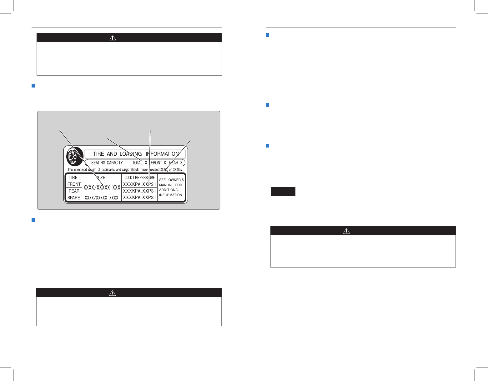
MAINTENANCEMAINTENANCE
WARNING
Using tires that are excessively worn or improperly inflated can cause
a crash in which you can be seriously hurt or killed.
Follow all instructions in this owner’s manual regarding tire inflation
and maintenance.
Tire and Loading Information Label
The label attached to the driver’s doorjamb provides necessary tire and
loading information.
Original
tire sizes
Tire and Wheel Replacement
Replace your tires with radials of the same size, load range, speed rating, and
maximum cold tire pressure rating (as shown on the tire’s sidewall). Using tires
of a different size or construction can cause certain vehicle systems to work
incorrectly. It is best to replace all four tires at the same time. If that isn’t possible,
replace the front or rear tires in pairs.
If you change or replace a wheel, make sure that the wheel’s specications match
those of the original wheels. Only use TPMS-specified wheels approved for your
vehicle.
Number of
people your
vehicle can
carry
Proper cold
tire pressure
Total weight
your vehicle
can carry
(do not exceed)
Tire Service Life
The life of your tires is dependent on many factors, including driving habits, road
conditions, vehicle loading, inflation pressure, maintenance history, speed, and
environmental conditions (even when the tires are not in use).
In addition to regular inspections and ination pressure maintenance, it is
recommended that you have annual inspections performed once the tires reach
ve years old. All tires, including the spare, should be removed from service after
10 years from the date of manufacture, regardless of their condition or state of
wear.
Winter Tires
If driving on snowy or frozen roads, mount all season tires marked “M+S”, snow
tires, or tire chains; reduce speed; and maintain sufcient distance between
vehicles when driving. For winter tires, select the size and load ranges that are the
same as the original tires, and mount them to all four wheels.
Tire Chains
Install tire chains on the front tires only. Because your vehicle has limited tire
clearance, we strongly recommend using the following chains: Cable type: SCC
Super Z-6# SZ-429. Mount chains as tightly as you can, and make sure that they
do not touch the brake lines or suspension.
NOTICE
Traction devices that are the wrong size or improperly installed can damage your
vehicle’s brake lines, suspension, body, and wheels. Stop driving if they are hitting
any part of the vehicle.
WARNING
Using the wrong chains, or not properly installing chains, can damage the
brake lines and cause a crash in which you can be seriously injured or killed.
Follow all instructions in this guide regarding the selection and use of tire
chains.
WARNING
Installing improper tires on your vehicle can affect handling and stability.
This can cause a crash in which you can be seriously hurt or killed.
Always use the size and type of tires recommended in the Owner’s Manual.
132 | | 133
Page 71
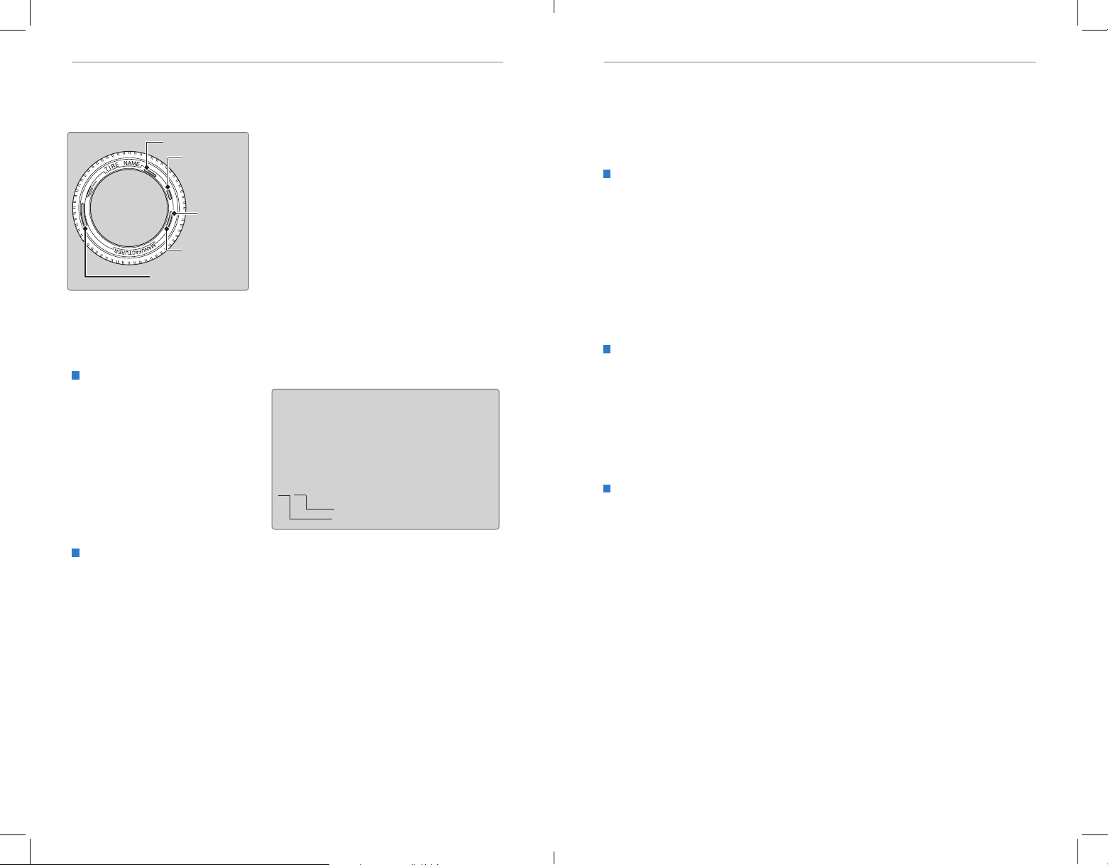
MAINTENANCEMAINTENANCE
Tire size
Tire
identification
number (TIN)
Maximum
tire load
Maximum
tire pressure
Tire size
DOT B97R FW6X 2209
DOT: This indicates that the tire meets all
requirements of the U.S. Department of
T
ransportation.
B97R: Manufacturer’s identication mark
FW6X: Tire type code
22 09: Date of Transportation
Year
Week
Tire Labeling
The tires that came on your vehicle have a number of markings. Those you
should be aware of are described below.
Tire Identification Number (TIN)
The tire identication number
(TIN) is a group of numbers
and letters that look like the
example below. TIN is located
on the sidewall of the tire.
Glossary of Tire Terminology
Cold Tire Pressure – The tire air pressure when the vehicle has been
parked for at least three hours or driven less than 1 mile (1.6 km).
Load Rating – The maximum load that a tire is rated to carry for a given
inflation pressure.
Maximum Ination Pressure – The maximum tire air pressure that the tire
can hold.
Maximum Load Rating – The load rating for a tire at the maximum
permissible ination pressure for that tire.
Recommended Ination Pressure – The cold tire ination pressure
recommended by the manufacturer.
Treadwear Indicators (TWI) – The projections within the principal grooves
designed to give a visual indication of the degrees of wear of the tread.
134 | | 135
Here is an example of what each marking
means:
215/70R16 100S
• 215: tire width in millimeters
• 70: aspect ratio (tire section height as a
percentage of its width)
• R: tire construction code (radial)
• 16: rim diameter in inches
• 100: load index (code indicating
maximum load tire can carry)
• S: speed symbol (code indicating
maximum speed rating)
DOT Tire Quality Grading
The tires on your vehicle meet all U.S. Federal Safety Requirements. All tires are
also graded for treadwear, traction, and temperature performance according
to Department of Transportation (DOT) standards. The following explains these
gradings.
Uniform Tire Quality Grading
Quality grades can be found where applicable on the tire sidewall between tread
shoulder and maximum section width.
For example:
Treadwear 200
Traction AA
Temperature A
All passenger car tires must conform to Federal Safety Requirements in
addition to these grades.
Treadwear
The treadwear grade is a comparative rating based on the wear rate of the tire
when tested under controlled conditions on a specified government test course.
For example, a tire graded 150 would wear one and one-half (1 1/2) times as well
on the government course as a tire graded 100. The relative performance of
tires depends upon the actual conditions of their use, however, and may depart
signicantly from the norm due to variations in driving habits, service practices,
and differences in road characteristics and climate.
Traction
The traction grades, from highest to lowest, are AA, A, B, and C. Those grades
represent the tire’s ability to stop on wet pavement as measured under controlled
conditions on specified government test surfaces of asphalt and concrete. A tire
marked C may have poor traction performance.
WARNING: The traction grade assigned to this tire is based on straight-ahead
braking traction tests, and does not include acceleration, cornering, hydroplaning,
or peak traction characteristics.
Page 72
MAINTENANCEMAINTENANCE
Temperature
The temperature grades are A (the highest), B, and C, representing the tire’s
resistance to the generation of heat and its ability to dissipate heat when tested
under controlled conditions on a specied indoor laboratory test wheel. Sustained
high temperature can cause the material of the tire to degenerate and reduce
tire life, and excessive temperature can lead to sudden tire failure. The grade
C corresponds to a level of performance which all passenger car tires must
meet under the Federal Motor Vehicle Safety Standard No. 109. Grades B and
A represent higher levels of performance on the laboratory test wheel than the
minimum required by law.
WARNING: The temperature grade for this tire is established for a tire that
is properly inated and not overloaded. Excessive speed, underination, or
excessive loading, either separately or in combination, can cause heat buildup
and possible tire failure.
Tire Pressure Monitoring System (TPMS) - Required Federal
Explanation
U.S. models only
Each tire, including the spare (if provided), should be checked monthly
when cold and inated to the ination pressure recommended by the
vehicle manufacturer on the vehicle placard or tire ination pressure label.
(If your vehicle has tires of a different size than the size indicated on the
vehicle placard or tire ination pressure label, you should determine the
proper tire inflation pressure for those tires.)
As an added safety feature, your vehicle has been equipped with
a tire pressure monitoring system (TPMS) that illuminates a low
tire pressure telltale when one or more of your tires is significantly
under-inflated.
Accordingly, when the low tire pressure telltale illuminates, you should stop
and check your tires as soon as possible, and inate them to the proper
pressure.
Driving on a signicantly under-inated tire causes the tire to overheat and
can lead to tire failure. Under-inflation also reduces fuel efficiency and tire
tread life, and may affect the vehicle’s handling and stopping ability.
Please note that the TPMS is not a substitute for proper tire maintenance,
and it is the driver’s responsibility to maintain correct tire pressure, even if
under-inflation has not reached the level to trigger illumination of the TPMS
low tire pressure telltale.
Models with information display
Your vehicle has also been equipped with a TPMS malfunction
indicator to indicate when the system is not operating properly.
The TPMS malfunction indicator is provided by a separate telltale,
which displays the symbol “TPMS” when illuminated.
When the malfunction indicator is illuminated, the system may not be
able to detect low tire pressure as intended.
Models with multi-information display
Your vehicle has also been equipped with a TPMS malfunction indicator to
indicate when the system is not operating properly. The TPMS malfunction
indicator is combined with the low tire pressure telltale. When the system
detects a malfunction, the telltale will flash for approximately one minute
and then remain continuously illuminated. This sequence will continue upon
subsequent vehicle start-ups as long as the malfunction exists.
When the malfunction indicator is illuminated, the system may not be able
to detect or signal low tire pressure as intended.
TPMS malfunctions may occur for a variety of reasons, including the
installation of replacement or alternate tires or wheels on the vehicle that
prevent the TPMS from functioning properly.
Always check the TPMS malfunction telltale after replacing one or more
tires or wheels on your vehicle to ensure that the replacement or alternate
tires and wheels allow the TPMS to continue to function properly.
136 | | 137
Page 73

SPECIFICATIONSMAINTENANCE
*1:LX model
Model Honda Odyssey
Engine Specifications
Fuel
*1:Touring models
P235/65R17 103T
*Not available on all models
35W (D2S)
*
Brake Fluid
Automatic Transmission Flui
Engine Oi
Engine Coolan
W
Canada: 4.5 US qt (4.3 ℓ)
Testing of Readiness Codes
Your vehicle has “readiness codes” as part of the onboard self-diagnostic system.
Some states refer to these codes as a test to see if your vehicle’s emissions
components are working properly. The codes may not be read if you go through the
testing just after the battery has gone dead or been disconnected.
To check if they are set, turn the vehicle on without starting the engine. The
malfunction indicator lamp will come on for several seconds. If it goes off, the
readiness codes are set. If it blinks ve times, the readiness codes are not set.
If you are required to have your vehicle tested before the readiness codes are set,
prepare the vehicle for retesting by doing the following:
1. Fill the gas tank to approximately 3/4 full.
2. Park the vehicle and leave the engine off for 6 hours or more.
3. Make sure the ambient temperature is between 40°F and 95°F (4°C and 35°C).
4. Start the engine without touching the accelerator pedal, and let it idle for 20
seconds.
5. Keep the vehicle in Park (P). Increase the engine speed to 2,000 rpm, and hold it
there for about 3 minutes.
6. Let the engine idle with your foot off the accelerator for 20 seconds.
7. Select a nearby, lightly traveled major highway where you can maintain a speed
of 50 to 60 mph (80 to 97 km/h) for at least 20 minutes. Drive on the highway with
the vehicle in Drive. Do not use cruise control. When trafc allows, drive for 90
seconds without using the accelerator pedal. (Vehicle speed may vary slightly;
this is OK.) If you cannot do this for a continuous 90 seconds because of trafc
conditions, drive for at least 30 seconds, then repeat two more times (for a total of
90 seconds).
8. Drive in city/suburban trafc for at least 10 minutes. When trafc conditions
allow, let the vehicle coast for several seconds without using the accelerator
pedal or the brake pedal.
9. Park the vehicle and leave the engine off for 30 minutes.
The readiness codes are erased when the battery is disconnected, and set again
only after several days of driving under a variety of conditions.
If a testing facility determines that the readiness codes are not set, you may be
requested to return at a later date to complete the test, or see your dealer.
SPECIFICATIONS
Vehicle
No. of Passengers:
Front2
Rear 2nd Row3 (2
Total8 (7
Weights:
Gross Vehicle
Weight Rating
Gross Axle Weight
Rating (Front)
Gross Axle Weight
Rating (Rear)
Gross Combined
Weight Rating
Air Conditioning:
Refrigerant Type HFC-134a (R-134a)
Charge Quantity 24.9 – 26.6 oz (705 – 755 g)
Lubricant Type ND-OIL8
3rd Row3
U.S.: 6,019 lbs (2,730 kg)
Canada: 2,730 kg
U.S.: 2,910 lbs (1,320 kg)
Canada: 1,320 kg
U.S.: 3,197 lbs (1,450 kg)
Canada: 1,450 kg
U.S.: 8,477 lbs (3,845 kg)
Canada: 3,845 kg
*1
)
*1
)
Engine and Fuel
Displacement 212 cu-in (3,471 cm3)
Spark PlugsNGK DILZKR7A11G
Fuel:
Type
Fuel Tank Capacity21 US gal (79.5 ℓ)
Unleaded gasoline, Pump octane
number of 87 or higher
Tires
Size
Regular
Pressure
psi(kPa[kgf/cm
Size T135/80D17 103M
Compact
Pressure
Spare
psi(kPa[kgf/cm
Regular
Wheel Size
Compact Spare 17 x 4T
2
])
2
])
P235/60R18 102T
33 (230 [2.3])
35 (240 [2.4])
60 (420 [4.2])
17 x 7J
18 x 7J
*1
*1
*1
Light Bulbs
Headlights (Low Beam)
Headlights (High Beam)
*
Fog Lights
Front Turn Signal/Parking/Side
Marker Lights
Side Turn Signal Lights
(on Door Mirrors)
Brake Lights
Rear Side Marker/Taillights LED
Rear Turn Signal Lights
Back-Up Lights 21W
High-Mount Brake Light 16W
Rear License Plate Lights
Map Lights (Front) 5W
Map Lights (Rear)
Cargo Area Light 8W
Vanity Mirror Lights
Door Courtesy Lights 3.8W (2CP)
Glove Box Light
Foot Light
*
*
55W (H11)
60W (HB3)
55W (H11)
28/8W
LED
21W
21W (Amber)
DELsthgilliaT
5W
5W
1.4W
1.4W
LED
*
Fluids
Specified Honda Heavy Duty Brake Fluid DOT 3
Specified
CapacityChange3.3 US qt (3.1 ℓ)
Honda ATF DW-1
(automatic transmission fluid)
l
Recommended
Capacity
·Honda Genuine Motor Oil 0W-20
·API Premium-grade 0W-20 detergent oil
t
Specified Honda Long-Life Antifreeze/Coolant Type2
Ratio 50/50 with distilled water
Capacity
1.93 US gal (7.3 ℓ)
(change including the remaining
0.225 US gal (0.85 ℓ) in the reserve tank)
asher Fluid
Tank Capacity
d
Change 4.2 US qt (4.0 ℓ)
Change
including
4.5 US qt (4.3 ℓ)
filter
U.S.: 2.6 US qt (2.5 ℓ)
138 | | 139
Page 74

CUSTOMER INFORMATIONCUSTOMER INFORMATION
CUSTOMER INFORMATION
Learn about information specic to you as a Honda customer and how to get help.
Frequently Asked Questions/Troubleshooting
Below are some frequently asked questions and troubleshooting items that you may
have about the vehicle.
Q: How do I set the vehicle clock?
A: For vehicles without navigation, see page 55. For vehicles with navigation, the
time is automatically set using GPS signals.
Q: Why doesn’t the vehicle start when I press the ENGINE START/STOP button?
A: The brake pedal must be pressed to start the engine.
Q: What is the AUTO setting on my headlight lever?
A: When in the AUTO position, the vehicle’s exterior lights will automatically turn
on or off depending on the ambient lighting.
Q: Why won’t the driver’s door unlock when I grab the door handle, even though
the keyless access remote is within range?
A: If you pull the handle too quickly, the system may not have time to conrm the
door is unlocked. Wait to hear a beep to conrm the door is unlocked. If you are
wearing gloves, the system may be slow to respond.
Q: After my battery was disconnected or went dead, the audio system is asking for
a code. Where do I nd this?
A: In most cases, you do not need to enter a code. Turn on the vehicle and the
audio system, and press and hold the power button until the system reactivates.
Q: Why can’t I operate Pandora® through the audio system?
A: Audio may be streaming through Bluetooth® Audio. Make sure Pandora mode
is selected and the phone cable is properly connected to the USB adapter.
Some phones may prompt you to “Allow” a connection.
Q: Is my phone compatible with Bluetooth features?
A: Visit handsfreelink.honda.com (U.S.) or www.handsfreelink.ca (Canada) to
check phone compatibility for Bluetooth® Audio, Bluetooth® HandsFreeLink®,
and SMS text messaging.
Q: Why can’t I select an item using the interface dial?*
A: To prevent driver distraction, certain items are limited are inoperable while the
vehicle is moving. Use voice commands or pull over to select the items.
Q: Where can I nd the vehicle identication number (VIN)?
A: Check the label on the driver’s doorjamb.
Contact Us
Honda dealer personnel are trained professionals. They should be able to answer
all your questions. If you encounter a problem that your dealership does not solve
to your satisfaction, please discuss it with the dealership’s service manager or
general manager. If you are dissatised with the decision made by the dealership’s
management, contact Honda Automobile Customer Service.
U.S. Owners:
American Honda Motor Co., Inc.
Honda Automobile Customer Service
1919 Torrance Blvd.
Mail Stop 500-2N-7A
Torrance, CA 90501-2746
Tel: (800) 999-1009
In Puerto Rico and
the U.S. Virgin Islands:
Bella International
P.O. Box 190816
San Juan, PR 00919-0816
Tel: (787) 620-7546
When you call or write, please give us the following information:
• Vehicle Identication Number
• Date of purchase
• Odometer reading of your vehicle
• Your name, address, and telephone number
• A detailed description of the problem
• Name of the dealer who sold the vehicle to you
Canadian Owners:
Honda Canada, Inc.
Customer Relations
180 Honda Blvd.
Markham, ON
L6C 0H9
Tel: (888) 946-6329
Fax: (877) 939-0909
e-mail: [email protected]
Q: Every time I press the Talk button, the system gives me voice prompts. Can I turn
these off?*
A: Press SETTINGS. Use the interface dial to select System Settings then Voice
Rec. For the Voice Prompt option, select Off.
*if equipped
140 | | 141
*if equipped
Page 75

VOICE COMMAND INDEXCUSTOMER INFORMATION
Honda Roadside Assistance
24-hour emergency road service is available to you in the United States and Canada
throughout your 3-year/36,000-mile warranty term. Services include jump starting,
flat tire and lockout assistance, towing, and more (limitations apply).
Call (866) 864-5211 (U.S.) or (800) 465-7587 (Canada).
Warranty Coverages
Below is a brief summary of the warranties covering your new vehicle.
New Vehicle Limited Warranty: Covers your new vehicle, except for the emissions
control system and accessories, against defects in materials and workmanship.
Emissions Control Systems Defects Warranty and Emissions Performance
Warranty: Covers your vehicle’s emissions control systems. Time, mileage, and
coverage are conditional.
Seat Belt Limited Warranty: Covers seat belts that fail to function properly.
Rust Perforation Limited Warranty: Covers all exterior body panels that rust through
from the inside.
Accessory Limited Warranty: Covers Honda accessories.
Replacement Parts Limited Warranty: Covers all Honda replacement parts against
defects in materials and workmanship.
Replacement Battery Limited Warranty: Provides prorated coverage for a
replacement battery purchased from a Honda dealer.
Replacement Muffler Lifetime Limited Warranty: Covers a replacement muffler for
the duration of the ownership.
Restrictions and exclusions apply to all these warranties. See the Warranty Manual
on the Owner Information CD or at owners.honda.com (U.S.) or www.myhonda.ca
(Canada) for complete descriptions of each warranty, including time, mileage, and
other conditional limitations.
Your vehicle’s original tires are covered by their manufacturer. Tire warranty
information can be found on the Owner Information CD or at owners.honda.com
(U.S.) or www.myhonda.ca (Canada).
VOICE COMMAND INDEX
Learn about all available voice commands to help you operate the vehicle. Available
on vehicles with navigation.
Press the Talk button before you say a command. To view a list of available
commands in the vehicle, press INFO and use the interface dial to select Voice Info.
Select a category to hear the commands read aloud.
Global Commands
The system accepts these commands on any screen.
• Voice help
• Display menu
• Display setting
• Display navigation
• Display information
Navigation Commands
The system accepts these commands on the map/guidance screen.
General Commands
• Display map
• Display map guide (when en route, shows the next guidance point)
• Go home
Map Display Commands
• Display current location
• Display/Hide (specify icon type):
− ATM
− gas station
− restaurant
− post office
− grocery store
− lodging (hotel, motel)
− parking garage
− parking lot
− school
• Display audio
• Display phone
• Cancel
• What is today’s date?
• What time is it?
− hospital
− freeway exit information
− traffic
− traffic speeds
− traffic icons
− traffic incidents
• Display north up
• Display heading up
• Display 3D map
• Display zoom in
• Display zoom out
142 | | 143
Page 76

VOICE COMMAND INDEXVOICE COMMAND INDEX
Navigation Commands (continued)
Find Place Commands
• Find nearest (specify place):
− Fuel and auto
− Honda dealers
− Gas station
− Auto parts & electronics
− Auto repair & maintenance
− Car wash & detailing
− Motorcycle dealers
− Other car dealerships
− Roadside assistance
− ATM
− Bank
− Check cashing
− Currency exchange
− Community
− Business
− City hall
− Civic center
− Convention center
− Court house
− Higher education
− Library
− Post office
− School
− Emergency room
− Hospital
− Police station
− Veterinarian
− Lodging
− Bed & breakfast
− Hotel
− Resort
− Recreation
− Amusement park
− Golf course
− Historical monument
− Marina
− Movie theater
− Museum
− Park
− Performing arts
− Sports complex
− Tourist attraction
− Restaurant
− American restaurant
− Californian restaurant
− Chinese restaurant
− Coffee shop
− Continental restaurant
− Fast food
− French restaurant
− German restaurant
− Greek restaurant
− Indian restaurant
− Italian restaurant
− Japanese restaurant
− Korean restaurant
− Mexican restaurant
− Pizza
− Seafood restaurant
− Thai restaurant
− Vegetarian restaurant
− Vietnamese restaurant
− Other restaurant
− Shopping
− Shopping area
− Accessory store
− Book store
− Clothing store
− Grocery store
− Home improvement store
− Mall
− Office supply store
− Pharmacy
− Pet food store
− Sewing store
− Shoe store
− Sporting goods store
− Toy store
− Travel center
− Airport
− Automobile club
− Bus station
− Camping
− Commuter rail station
− Ferry terminal
− Named place
− Park & ride
− Parking garage
− Parking lot
− Rental car agency
− Rest area
− Ski area
− Tourist information
− Train station
− Travel agency
− Truck stop
Route Commands
The system accepts these commands when a route is set.
• How long to the destination?
• How far to the destination?
• Display destination map
• Display entire route
• Cancel route
• Repeat guidance
144 | | 145
Page 77

VOICE COMMAND INDEXVOICE COMMAND INDEX
Climate Control Commands
The system accepts these commands on most screens.
• Climate control automatic
(maintains selected temperature)
• Climate control on*
• Climate control off*
• Air conditioner on*
• Air conditioner off*
• Climate control defrost on*
• Climate control defrost off*
• Rear defrost on*
• Rear defrost off*
• Climate control fresh air
• Climate control recirculate
• Climate control sync on*
• Climate control sync off*
• Climate control vent
• Climate control bi-level (vent and
floor)
• Climate control floor
• Climate control floor and defrost
• Climate control mode automatic
• Fan speed up
• Fan speed down
• Fan speed # (#: 1 to 7)
• Fan automatic
• Rear lock on
• Rear lock off
• Temperature up
• Temperature down
• Driver temperature up
• Driver temperature down
• Passenger temperature up
• Passenger temperature down
• Temperature max heat
• Temperature max cool
• Driver temperature max heat
• Driver temperature max cool
• Passenger temperature max heat
• Passenger temperature max cool
• Front climate control automatic
• Front climate control off
• Rear climate control automatic
• Rear climate control off
• Rear climate control vent
• Rear climate control bi-level
• Rear climate control floor
• Rear fan speed up
• Rear fan speed down
• Rear fan speed # (#:1 to 5)
• Rear temperature up
• Rear temperature down
• Rear temperature max heat
• Rear temperature max cool
• Temperature # degrees
(#: 57 to 87°F)
• Driver temperature # degrees
(#: 57 to 87°F)
• Passenger temperature # degrees
(#: 57 to 87°F)
Audio Commands
The system accepts these commands on most screens. Audio volume levels
cannot be controlled using voice commands.
FM/AM Radio Commands
• Audio on*
• Audio off*
• Radio on*
• Radio off*
• Radio select FM
• Radio select AM
• Radio tune to # FM (#: frequency,
e.g., 95.5)
• Radio tune to # AM (#: frequency,
e.g., 1020)
• Radio seek up
• Radio seek down
• Radio next station
Disc Commands
• Disc play
• Disc play track # (#: 1 to 30)
• Disc skip forward
• Disc skip back
• Disc track random*
• Disc track repeat*
• Disc track scan*
• Disc folder up
• Disc folder down
• Disc folder random*
• Disc folder repeat*
• Disc folder scan*
• Disc normal play
• Radio preset # (#: 1 to 12)
• Radio FM preset # (#: 1 to 12)
• Radio AM preset # (#: 1 to 6)
• Radio scan*
SiriusXM® Radio Commands
• Radio select XM
• XM channel # (#: 0 to 255)
• XM channel up
• XM channel down
• XM category up
• XM category down
• XM preset # (#: 1 to 12)
• XM scan*
• XM category mode
• XM channel mode
Hard Disc Drive Commands
• Hard disc drive play
• Hard disc drive play track # (#: 1-30)
• Hard disc drive skip forward
• Hard disc drive skip back
• Hard disc drive album up*
• Hard disc drive album down*
• Hard disc drive track up
• Hard disc drive track down
• Hard disc drive playlist up*
• Hard disc drive playlist down*
• Hard disc drive track repeat*
• Hard disc drive track random*
• Hard disc drive track scan*
• Hard disc drive normal play
• What/Who am I listening to?
• Who is this?
• What’s playing?
• Who’s playing?
• What album is this?
* These commands toggle the function on and off, so the
command may not match your intended action.
146 | | 147
*These commands toggle the function on and off, so the
command may not match your intended action.
Page 78

VOICE COMMAND INDEXVOICE COMMAND INDEX
Audio Commands (continued)
USB Commands
• USB play
• USB play track # (#: 1 to 30)
• USB skip forward
• USB skip back
• USB track random*
• USB track repeat*
• USB track scan*
• USB folder up
• USB folder down
• USB folder random*
• USB folder repeat*
• USB folder scan*
• USB normal play
iPod® Commands
• iPod play
• iPod play track # (#: 1-30)
• iPod skip forward
• iPod skip back
• iPod track shufe*
• iPod album shufe*
• iPod track repeat*
• iPod normal play
• What/Who am I listening to?
• Who is this?
• What’s playing?
• Who’s playing?
• What album is this?
Pandora® Commands
• Pandora play*
• Pandora skip forward
• Pandora station up
• Pandora station down
• Pandora pause*
• Pandora resume*
• Pandora thumbs up
• Pandora thumbs down
Aha™ Commands
• Aha radio play
• Aha radio skip forward
• Aha radio skip back
• Aha radio station up
• Aha radio station down
• Aha radio pause
• Aha radio like
• Aha radio dislike
Bluetooth® Audio Commands
• Bluetooth audio play
• Bluetooth audio skip forward
• Bluetooth audio skip back
• Bluetooth audio pause
• Bluetooth audio resume
• Bluetooth audio group up
• Bluetooth audio group down
Commands may not work on some
phones or devices.
AUX Commands
• Auxiliary play
Audio Commands (continued)
Song By Voice™ Commands
Available for tracks stored on the HDD or iPod®.
• Music search
• List album (specify album)
• List artist (specify artist)
• List composer (specify composer)
• List genre (specify genre)
• List playlist (specify playlist)
• Play album (specify album)
• Play artist (specify artist)
• Play genre (specify genre)
• List playlist (specify playlist)
• Play song (specify song)
• What/Who am I listening to?
• Who is this?
• What’s playing?
• Who’s playing?
• What album is this?
• Play composer (specify composer)
Rear Audio Commands
On vehicles with rear entertainment system, voice commands for certain rear
audio functions are available.
To view a list of rear audio commands in the vehicle, press INFO and use the
interface dial to select Voice Info. Select Rear Audio Commands, and press the
interface dial to hear the commands read aloud.
Phone Commands
The system accepts these commands on most screens.
• Dial/call by number
• Dial/call by voice tag
Info Commands
The system accepts these commands on most screens.
• Trip computer
• Traffic information
• Display clock
• Display wallpaper
On-screen Commands
The system accepts these commands on any screen where applicable. All
available commands are highlighted in yellow when you press the Talk button.
• Next (or Down)
• Previous (or Up)
• Return
• OK (excluding Startup Confirmation screen)
• Delete
*These commands toggle the function on and off, so the
command may not match your intended action.
148 | | 149
Page 79

INDEXINDEX
INDEX
ABS .............................................................25
Active Head Restraints ...................................43
Address .............................................................87
Advanced Airbags .............................................9
Aha™ .............................................................73
Aha™ Commands ...........................................148
Airbags ...............................................................9
About Your Airbags ......................................11
Advanced Airbags .........................................9
Airbag Care ...................................................14
Front Airbags (SRS) .......................................9
Passenger Airbag Off Indicator .................12
Side Airbags ..................................................10
Side Curtain Airbags ....................................10
SRS (Supplemental Restraint System)
Indicator.............................................11
System Components ....................................13
System Indicators ........................................11
Air Conditioning System..................................52
Anti-Lock Brake System (ABS) ................25, 97
Audio Commands ...........................................147
Audio Operation ...............................................56
Auxiliary Input Jack .....................................56
Bluetooth® Audio ...................................62, 71
Compact Disc (CD) .................................60, 68
DVD .............................................................74
FM/AM Radio ..........................................59, 66
Hard Disc Drive (HDD) Audio .....................69
HDMI ............................................................. 75
HondaLink featuring Aha™ ........................73
Intelligent Multi-Information Display
(i-MID) ..........................................58, 64
iPod® .......................................................61, 70
Pandora® .................................................63, 72
Rear Audio Commands ..............................149
Rear Entertainment System ........................74
SiriusXM® Radio ...........................................67
Sound .............................................................56
Steering Wheel Controls .............................57
Touchscreen Operation ..............................65
USB Flash Drive ............................................61
USB Port ........................................................56
Wireless Headphones .................................75
Automatic Dimming Rearview Mirror ...........48
Automatic Headlights ......................................39
AUX Commands..............................................148
Auxiliary Input Jack .........................................56
Battery ...........................................................128
Blind Spot Information (BSI) ..................25, 102
Bluetooth® Audio .......................................62, 71
Bluetooth® Audio Commands ......................148
Bluetooth® HandsFreeLink® (HFL) .................78
Call History ....................................................82
E-Mail .............................................................83
HFL Controls ..................................................78
Making a Call ................................................81
Pairing a Phone ........................................... 80
Phonebook ....................................................81
SMS Text Messaging ..................................83
Speed Dial .....................................................82
Voice Recognition Tips ................................79
Brake Assist System........................................97
Brake system ..............................................24, 25
Braking .............................................................96
Brightness Control ...........................................38
BSI ...............................................25, 27, 102
Call History ........................................................82
Carbon Monoxide Gas.......................................4
Cargo Area Lights ............................................39
Change a Setting ..............................................55
Changing a Flat Tire .......................................111
Changing Wiper Blades ................................129
Charging system...............................................24
Child Safety .......................................................15
Childproof Door Locks .................................33
Protecting Child Passengers ......................15
Protecting Infants ........................................16
Protecting Larger Children .........................21
Protecting Smaller Children .......................17
Child Seat ..........................................................17
Adding Security with a Tether ...................20
LATCH-Compatible Child Seat ....................18
Selecting a Child Seat .................................17
Climate Control Commands ..........................146
Climate Control System ...................................53
Clock .............................................................55
Compact Disc (CD) .....................................60, 68
Contact Us .......................................................141
Coolant ...........................................................127
Cool Box.............................................................51
Cruise Control .............................................27, 98
Customer Information....................................140
Customized Features .......................................55
Dashboard and Ceiling Controls ......................2
Daytime Running Lights (DRL)........................25
Destination ........................................................87
Detour .............................................................89
Dialing a Number .............................................81
Door Mirrors .....................................................48
Doors .......................................................31, 33
Sliding Doors .................................................34
DOT Tire Quality Grading ..............................135
Driving .............................................................90
Blind Spot Information (BSI) ....................102
Braking ...........................................................96
Cruise Control ...............................................98
Forward Collision Warning (FCW) ...........100
Ignition ...........................................................95
Lane Departure Warning (LDW) ..............101
LaneWatch™ ................................................99
Maximum Load Limit ....................................91
Multi-View Rear Camera ..........................105
Parking Sensor System .............................103
Power Mode .................................................95
Rearview Camera .......................................104
Refueling ......................................................106
Shifting ...........................................................96
Towing a Trailer ............................................93
Driving Position Memory System ..................47
DRL ............................................................. 25
Dual Screen ......................................................77
DVD .............................................................74
ECO indicator ....................................................27
Electronic Stability Control (ESC) ..................97
Emergency Engine Stop ................................110
Emergency Towing ........................................110
Engine and Fuel ..............................................139
Engine Coolant................................................127
Engine Oil.........................................................125
ENGINE START/STOP button .........................95
Exterior lights ..............................................27, 39
Fastening a Seat Belt ........................................7
FCW ...............................................25, 27, 100
Find Nearest Place ..........................................88
Find Place Commands ...................................144
Flat Tire ...........................................................111
Floor Mats .........................................................43
Fluids ...........................................................139
FM/AM Radio ..............................................59, 66
FM/AM Radio Commands .............................147
FM Traffic ..........................................................89
Fog lights .....................................................27, 39
Foot Brake .........................................................96
Forward Collision Warning (FCW) ...25, 27, 100
Frequently Asked Questions ........................140
Front Airbags (SRS) ...........................................9
Front Seats ........................................................41
Front Wipers .....................................................40
Fuel Information .............................................106
Fuse Locations................................................115
Garage Opener .................................................49
Hang-Up/Back button......................................78
Hard Disc Drive (HDD) Audio .........................69
Hazards .............................................................27
HDMI .............................................................75
Headlight-Wiper Integration ..........................40
Head Restraints ................................................42
High beams .......................................................27
Home Address ..................................................87
HomeLink® Garage Opener ............................49
HondaLink featuring Aha™ ............................73
Honda Roadside Assistance ........................142
HondaVAC® .......................................................50
Hood ........................................................... 124
Ignition .............................................................95
i-MID ....................................................... 58, 64
Immobilizer ........................................................27
Info buttons .......................................................29
Info Commands...............................................149
Information Display..........................................28
Instrument Panel ..............................................24
Condition Indicators ....................................26
Malfunction Indicators ................................24
On/Off Indicators ..........................................27
Intelligent Multi-Information Display
(i-MID) ..........................................58, 64
Interface dial...............................................79, 85
Interface Dial Feedback..................................86
Interior Lights....................................................38
Intermittent Wipers..........................................40
iPod® .......................................................61, 70
iPod® Commands ...........................................148
Jump Starting .................................................107
Key .............................................................30
Lane Departure Warning (LDW) ......25, 27, 101
LaneWatch™ ....................................................99
Lap/Shoulder Seat Belts ...................................5
LATCH-Compatible Child Seat ........................18
LDW ...............................................25, 27, 101
Light Bulbs.......................................................139
Lights .............................................................38
Locking the Doors ............................................31
Locking the Tailgate .........................................31
Lock Tab .............................................................33
Low fuel .............................................................26
Low oil pressure ...............................................24
Low tire pressure .............................................26
Maintenance...................................................121
Maintenance Minder™ .......................27, 122
Safety Precautions ....................................121
Service Codes .............................................123
Under the Hood ..........................................124
Malfunction indicator lamp ............................25
Map Display Commands ...............................143
Map Legend ......................................................89
Map Lights.........................................................38
Master Door Lock Switch ...............................33
Maximum Load Limit........................................91
MENU button ............................58, 64, 78, 79, 85
Mirrors .............................................................48
Moonroof ...........................................................37
Multi-Information Display ...............................29
Multi-View Rear Camera ..............................105
Navigation .........................................................84
Detour ............................................................89
Display and Controls ....................................85
150 | | 151
Page 80

INDEXINDEX
Entering a Destination .................................87
Find Nearest Place ......................................88
Home Address ..............................................87
Map Legend ..................................................89
Place Category .............................................88
Routing ...........................................................89
Steering Wheel Controls .............................84
Street Address ..............................................87
Traffic .............................................................89
Voice Command Tips ...................................84
Navigation Commands ..................................143
One-Motion Third-Row Magic Seat .............46
One-Touch Turn Signal ....................................39
On-screen Commands...................................149
Overheating.....................................................109
Pairing a Phone ................................................80
Pandora® .....................................................63, 72
Pandora® Commands ....................................148
Parking brake..............................................26, 96
Parking Sensor System .................................103
Passenger Airbag Off Indicator .....................12
Phone .............................................................80
Phonebook ........................................................81
PHONE button .............................................78, 79
Phone Commands ..........................................149
Pick-Up button ..................................................78
Place Category .................................................88
Playing a DVD ...................................................74
Power Door Mirrors.........................................48
Power Mode .....................................................95
Power Moonroof ..............................................37
Power sliding doors ...................................25, 34
Power tailgate ............................................25, 32
Power Windows ...............................................36
Readiness Codes............................................138
Rear Audio Commands..................................149
Rear Entertainment System (RES) .................74
Dual Screen ..................................................77
DVD .............................................................74
HDMI ............................................................. 75
Remote Control .............................................76
Wireless Headphones .................................75
Rear Seats .........................................................44
Rearview Camera...........................................104
Rearview Mirror ...............................................48
Rear Wiper ........................................................40
Refueling..........................................................106
Remote Battery Strength ..............................107
Remote Control .................................................76
Remote Transmitter .........................................30
Reporting Safety Defects................................23
Reverse Tilt Door Mirrors ...............................48
Roadside Assistance .....................................142
Route Commands ...........................................145
Routing .............................................................89
Safety Information .............................................3
Carbon Monoxide Gas ...................................4
Childproof Door Locks .................................33
Child Safety ...................................................15
Reporting Safety Defects ............................23
Safety Label Locations ................................22
Safety Messages ...........................................3
Seat Belts ............................................................5
Fastening a Seat Belt ....................................7
Lap/Shoulder Seat Belts ...............................5
Seat Belt Inspection ......................................6
Seat Belt Reminder ......................................26
Seat Belt with Detachable Anchor .............8
Shoulder Anchor ............................................7
Seat Heaters .....................................................54
Seats .............................................................41
Front Seats ....................................................41
Second-Row Seats ..........................44, 45, 46
Third-Row Seats .....................................44, 46
Select/reset knob .............................................28
SEL/RESET button ............................................29
Service Codes.................................................123
Settings .............................................................55
SETTINGS button .....................58, 64, 78, 79, 85
Setting the Clock ..............................................55
Shifting .............................................................96
Shift Lever Does Not Move ..........................108
Shoulder Anchor ................................................7
Side Airbags......................................................10
Side Curtain Airbags........................................10
SiriusXM® Radio ...............................................67
SiriusXM® Radio Commands ........................147
Sliding Doors.....................................................34
Smart Entry system ....................................24, 31
SMS Text Messaging ......................................83
Song By Voice™ Commands ........................149
Sound .............................................................56
Specifications .................................................139
Speed Dial .........................................................82
SRS (Supplemental Restraint System)
Indicator.......................................11, 24
Starter system ..................................................25
Steering Wheel.................................................47
Steering Wheel and Nearby Controls ............1
Steering Wheel Controls...........................57, 84
Street Address..................................................87
System Guidance Volume ...............................86
System message ..............................................26
Tailgate .............................................................31
Talk button .........................................................78
Text Messaging ................................................83
Third-Row Magic Seat ....................................46
Tire Chains .......................................................133
Tire Information ..............................................131
DOT Tire Quality Grading ..........................135
Ination Guidelines ....................................131
Tire and Loading Information Label ........132
Tire and Wheel Replacement ...................132
Tire Identication Number (TIN) ..............134
Tire Labeling ................................................134
Tire Service Life ..........................................133
Tire Terminology ......................................... 134
Wear Indicators .........................................131
Tire Pressure Monitoring System
(TPMS) ...............................25, 111, 136
Tires ...........................................................139
Tongue load .......................................................93
Touchscreen .....................................................65
Towing (emergency) ......................................110
Towing a Trailer ................................................93
TPMS .............................................25, 111, 136
Traffic .............................................................89
Troubleshooting ..............................................140
Turn Signal ..................................................27, 39
Under the Hood ..............................................124
Unlocking the Doors ........................................31
Unlocking the Tailgate .....................................31
USB Commands..............................................148
USB Flash Drive................................................61
USB Port ............................................................56
Vacuum .............................................................50
Vehicle Controls ...............................................30
Vehicle Stability Assist (VSA®) ..........25, 26, 97
Visual Index.........................................................1
Voice Command Index ..................................143
Voice Prompt ....................................................86
Voice Prompt Volume ......................................86
Voice Recognition Tips ..............................79, 84
VSA® ...........................................25, 26, 27, 97
Warranty Coverages .....................................142
Wear Indicators .............................................131
Windows............................................................36
Window Washer Fluid ...................................128
Winter Tires .....................................................133
Wiper Blades ..................................................129
Wiper Operation ...............................................40
Wireless Headphones .....................................75
152 | | 153
 Loading...