

Honda EB4000X EBSC-1000001 through 9999999, EB5000X EBPC-1000001 through 9999999, EB6500X EBLC-1000001 through 9999999 Owner's Manual
Owner’s Manual
Click to Save As
GENERATOR
EB4000X • EB5000X • EB6500X
© 2014 Honda Motor Co., Ltd.—All Rights Reserved
See page 80 for
Initial Use Instructions
The engine exhaust from this product
contains chemicals known to the State
of California to cause cancer, birth
defects or other reproductive harm.
California Proposition 65
This product contains or emits
chemicals know
California to cause cancer, birth defects
or other reproductive harm
Exhaust contains poisonous carbon
monoxide gas that can build up to
dangerous levels in closed areas.
Breathing carbon monoxide can
cause unconsciou
Never run the generator in a closed,
or even partly closed area where
peop
le may be
n to the state of
sness or death.
present.
Keep this owner’s manual handy so that you can refer to it at any time.
This owner’s manual is considered a permanent part of the generator
and should remain with the generator if resold.
The information and specifications included in this publication were in
effect at the time of approval for printing. Hon
reserves the right, however, to discontinue or change specifications or
design at any time without notice and without incurring any obligation
whatsoever.
da Motor Co., Ltd.

INTRODUCTION
Congratulations on your selection of a Honda generator. We are certain
you will be pleased with your purchase of one of the finest generators
on the market.
We want to help you get the best results from your new generator and
to
operate it safely. This manual contains all the information on how to
do that; please read it carefully.
As you read this manual, you will find information preceded by a
symbol. That information is intended to help you avoid damage
to your generator, other property, or the environment.
We suggest you read the Distribut
understand its coverage and your responsibilities of ownership. The
Distributor’s Limited Warranty is a separate document that should have
been given to you by your dealer.
When your generator needs scheduled maintenance, keep in mind that
yo
ur Honda servicing dealer is specially trained in servicing Honda
generators and is supported by the parts and service divisions of
American Honda. Your Honda servicing dealer is dedicated to your
satisfaction and will be pleased to answer your questions and concerns.
Best Wishes,
Honda Motor Co., Ltd.
or’s Lim
ited Warranty to fully
1

A FEW WORDS ABOUT SAFETY
Your safety and the safety of others are very important. And using this
generator safely is an important responsibility.
To help you make informed decisions about safety, we have provided
operating pr
manual. This information alerts you to potential hazards that could hurt
you or others.
ocedures and other information on labels and in this
Of course, it is not practical or possible to warn you about
hazards associated with operating or maintaining a generator. You
must use your own good judgment.
You will find important safety informati
includ
ing:
• Safety Labels — on the generator.
• Safety Messages — preceded by a safety alert symbol and one of
three signal words, DANGER, WARNING, or CAUTION.
These signal words mean:
You WILL be KILLED or SERIOUSLY HURT if
you don’t fo
You CAN be KILLED or SERIOUSLY HURT if
you don’t fo
You CAN be HURT if you don’t follow
instructions.
• Safety Headings — such as IMPORTANT SAFETY INFORMATION.
on in a variety of forms,
llow instructions.
llow instructions.
all the
• Safety Section — such as GENERATOR SAFETY.
• Instructions — how to use this generator correctly and safel
This entire book is filled with important safety informatio
read it carefully.
n — please
2
y.

CONTENTS
GENERATOR SAFETY .................................................................. 6
IMPORTANT SAFETY INFORMATION .........................................6
Operator Responsibility ..........................................................6
Carbon Monoxide Hazards...................................................... 6
Electric Shock Hazards...........................................................7
Fire and Burn Hazards ............................................................ 7
Refuel With Care ...................................................................8
SAFETY LABEL LOCATIONS......................................................9
CONTROLS & FEATURES ...........................................................10
COMPONENT & CONTROL LOCATIONS.................................... 10
CONTROLS ........................................................................... 12
Engine Switch.....................................................................12
Starter Grip ........................................................................ 12
Fuel Valve Lever .................................................................13
Voltage Selector Switch....................................................... 13
Auto Throttle System ..........................................................14
AC Circuit Protectors ...........................................................15
AC Circuit Breaker...............................................................16
Ground Fault Circuit Interrupter (GFCI) ................................... 17
Folding Handle .................................................................... 18
FEATURES ............................................................................ 19
Oil Alert System.................................................................. 19
Automatic Engine Stop Function ........................................... 19
Oil Alert Function ................................................................ 19
Overspeed Detection Function ..............................................19
Abnormal Voltage Detection Function .................................... 19
Auto Choke and Throttle Control System ..
iAVR (Intelligent Auto Voltage Regulator) ..
Fuel Gauge .........................................................................21
Ground Terminal .................................................................21
............................. 20
............................. 20
BEFORE OPERATION ................................................................. 22
ARE YOU READY TO GET STARTED?....................................... 22
Knowledge ......................................................................... 22
IS YOUR GENERATOR READY TO GO? ..................................... 22
Check the Engine ................................................................23
Check the GFCI...................................................................23
3

CONTENTS
OPERATION..............................................................................24
SAFE OPERATING PRECAUTIONS ............................................ 24
STARTING THE ENGINE .......................................................... 25
STOPPING THE ENGINE ..........................................................28
GFCI OPERATION CHECK........................................................ 29
AC OPERATION ..................................................................... 31
AC Applications .................................................................. 33
AC Receptacle Selection ...................................................... 34
Power Producing Circuits ..................................................... 34
Voltage Selector Switch....................................................... 35
AUTO THROTTLE SYSTEM ..................................................... 37
STANDBY POWER.................................................................. 38
.
Connections to a Building’s Electrical System
System Ground ...................................................................38
Special Requirements........................................................... 39
........................ 38
SERVICING YOUR GENERATOR .......
THE IMPORTANCE OF MAINTENANCE ..................................... 40
MAINTENANCE SAFETY ......................................................... 41
Safety Precautions .............................................................. 41
MAINTENANCE SCHEDULE ..................................................... 42
REFUELING............................................................................43
FUEL RECOMMENDATIONS..................................................... 44
ENGINE OIL LEVEL CHECK ......................................................45
ENGINE OIL CHANGE ............................................................. 46
ENGINE OIL RECOMMENDATIONS .....
AIR CLEANER SERVICE........................................................... 48
AIR CLEANER ELEMENT CLEANING..........................................50
SPARK PLUG SERVICE............................................................ 51
SPARK ARRESTER SERVICE .................................................... 53
SEDIMENT CUP CLEANING .....................................................54
STORAGE................................................................................. 55
STORAGE PREPARATION........................................................ 55
Cleaning............................................................................. 55
Fuel...................................................................................55
Engine Oil...........................................................................58
STORAGE PRECAUTIONS .......................................................59
REMOVAL FROM STORAGE ....................................................59
...........................................40
......................................47
4

CONTENTS
TRANSPORTING ....................................................................... 60
TAKING CARE OF UNEXPECTED PROBLEMS ................................ 61
ENGINE WILL NOT START.......................................................61
ENGINE LACKS POWER .......................................................... 62
NO POWER AT THE AC RECEPTACLES ....................................63
TECHNICAL INFORMATION ........................................................ 64
Serial Number Location ........................................................64
Carburetor Modification for High Altitude
Emission Control System Information..................................... 66
Air Index ............................................................................68
Specifications ..................................................................... 69
Wiring Diagram ................................................................... 70
CONSUMER INFORMATION........................................................ 72
Dealer Locator Information ...................................................72
Honda Publications ..............................................................72
Customer Service Information ............................................... 73
ASSEMBLY...............................................................................74
SAFETY ................................................................................ 74
The Importance of Proper Assembly ...................................... 74
Important Safety Precautions................................................ 75
ASSEMBLY............................................................................ 76
Unpacking .......................................................................... 76
Loose Parts (Wheel kit, handle and hanger)............................. 76
Wheel Kit Installation ...........................................................77
Handle Installation...............................................................78
Hanger Kit Installation.......................................................... 79
Operation
................. 65
INITIAL USE INSTRUCTIONS ......................................................80
ENGINE OIL ........................................................................... 80
FUEL ....................................................................................81
BEFORE OPERATION .............................................................. 82
REGISTRATION...................................................................... 82
INDEX......................................................................................83
QUICK REFERENCE INFORMATION......................... Inside back cover
5

GENERATOR SAFETY
IMPORTANT SAFETY INFORMATION
Honda generators are designed for use with electrical equipment that
has suitable
operator or damage to the generator and other property.
Most injuries or property damage can be prevented if you follow all
instructions in th
hazards are discussed below, along with the best way to protect
yourself and others.
Operator Responsibility
• Know how to stop the generator quickly in case of emergency.
• Understand the use of all generator controls, output receptacles, and
connections.
•
Be sure that anyone who operates the generator receives proper
structio
in
supervision.
Carbon Monoxide Hazards
A generator's exhaust contains toxic carbon monoxide, which you
cannot see or
MINUTES. To avoid carbon monoxide poisoning, follow these
instructions when operating a generator:
power requirements. Other uses can result in injury to the
is manual and on the generator. The most common
n. Do not let children operate the generator without parental
smell. Br
eathing carbon monoxide can KILL YOU IN
• Only run a generator OUTSIDE, far away from windows, doors, and
ven
ts.
• Never operate a generator inside a house, garage, basement, crawl
, or any enclosed or partially enclosed space.
space
• Never operate a generator near open doors or windows.
• Get fresh air and seek medical attention immediatel
you have inhaled carbon monoxide.
Early symptoms of carbon monoxide exposure include headache,
fatigu
e, shortness of breath, nausea, and dizziness. Continued exposure
to carbon monoxide can cause loss of muscular coordination, loss of
consciousness, and then death.
To alert you to potentially dangerous levels of carbon monoxide coming
fro
m a generator operating outside or from other sources, install battery
operated carbon monoxide alarms or plug-in carbon monoxide alarms
with battery back-up on every level of the home and outside sleeping
areas, according to the manufacturer’s instructions.
y if you suspect
6

GENERATOR SAFETY
Electric Shock Hazards
• The generator produces enough electric power to cause a serious
shock or electrocution if misused.
• Using a generator or electrical appliance in wet conditions, such as
rain or sno
are wet, could result in electrocution. Keep the generator dry.
• If the generator is stored outdoors, unprotected from the weather,
check the Ground F
other electrical components on the control panel before each use.
Moisture or ice can cause a malfunction or short circuit in electrical
components that could result in electrocution.
w, or near a pool or sprinkler system, or when your hands
ault Circuit Interrupter (GFCI) receptacle and all
• Do not connect to a building’s electrical s
switch has been installed by a qualified electrician.
Fire and Burn Hazards
• The exhaust system gets hot enough to ignite some materials.
– Keep the generator at least 3 feet (1 meter) away from buildings
and other equ
– Do not enclose the generator in any structure.
– Keep flammable materials away from the generator.
• The muffler becomes very hot during operation and remains hot for a
wh
ile after stopping the engine. Be careful not to touch the muffler
while it is hot. Let the engine cool before storing the generator
indoors.
ipment during operation.
stem unless an isolation
y
7

GENERATOR SAFETY
Refuel With Care
Gasoline is extremely flammable, and gasoline vapor can explode.
Allow the engine to cool if the generator has been in operation.
Refuel only outdoors in a well ventilated area with the engine off.
Do not refuel during operation.
Do not overfill the fuel tank.
Never smoke near gasoline, and keep other flames and sparks away.
ys store gasoline in an approved container.
Alwa
Make sure that any spilled fuel has been wiped up before starting the
engine
.
8
GENERATOR SAFETY
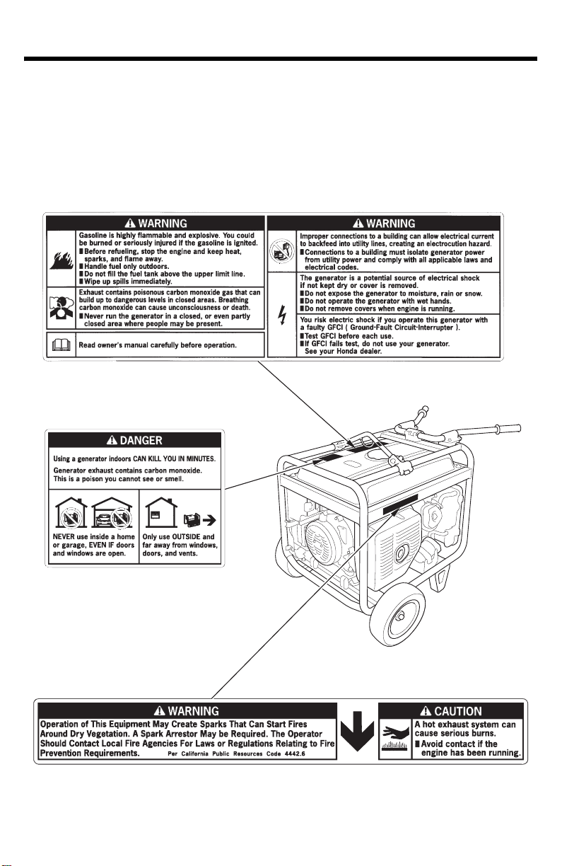
SAFETY LABEL LOCATIONS
These labels warn you of potential hazards that can cause serious
injury. Read them carefully.
If a label comes off or becomes hard
generator dealer for a replacement.
to read, contact your Honda
9
CONTROLS & FEATURES
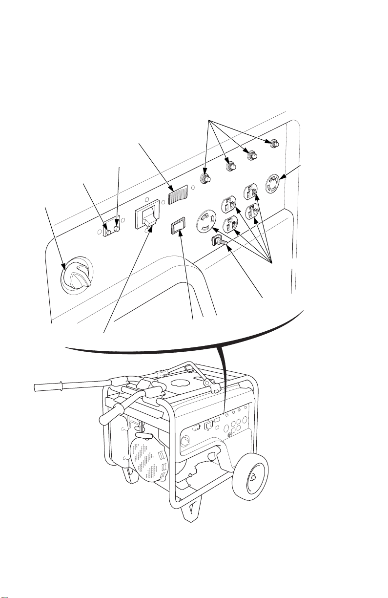
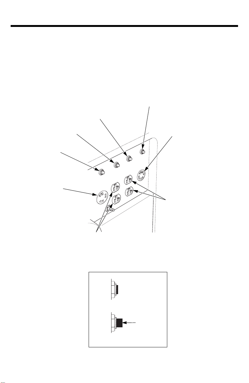
AC CIRCUIT PROTECTORS
120 V/240 V
AC RECEPTACLE
ENGINE SWITCH
GFCI RESET BUTTON
GFCI TEST BUTTON
VOLTAGE SELECTOR SWITCH
120 V AC RECEPTACLES
GROUND TERMINAL
AUTO THROTTLE
SWITCH
AC CIRCUIT BREAKER
*
*: Except EB4000X
COMPONENT & CONTROL LOCATIONS
Use the illustrations on these pages to
frequently used controls.
locate and identify the most
10
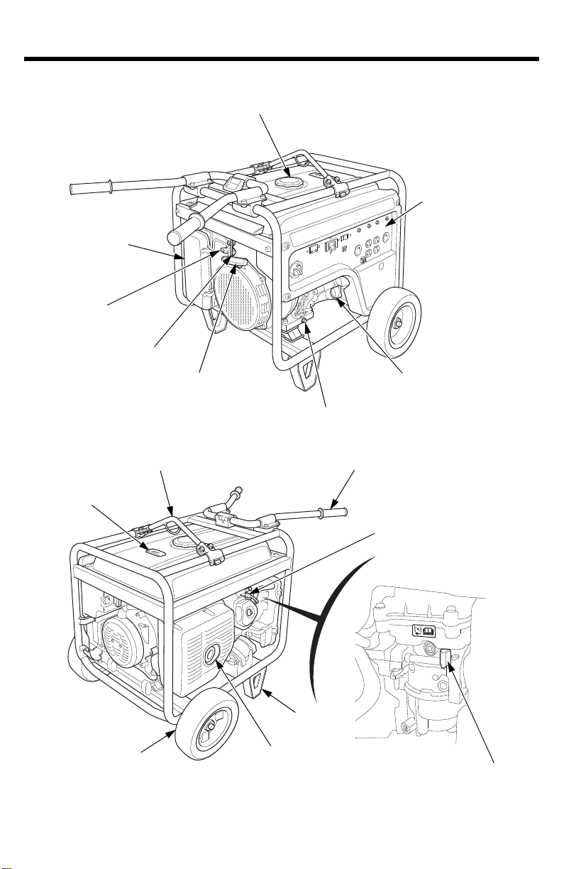
FUEL TANK CAP
CONTROL PANEL
OIL FILLER CAP/DIPSTICK
OIL DRAIN PLUG
STARTER GRIP
SEDIMENT CUP
FUEL VALVE LEVER
AIR CLEANER
LIFTING HANGER
FUEL GAUGE
HANDLE
SPARK PLUG
MANUAL CHOKE LEVER
STAND
MUFFLER
WHEEL
CONTROLS & FEATURES
11
CONTROLS & FEATURES
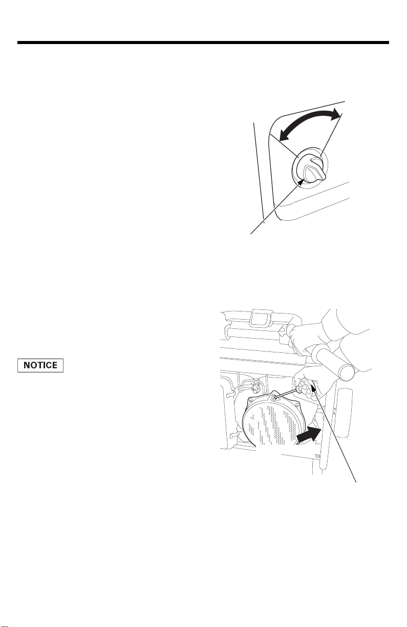
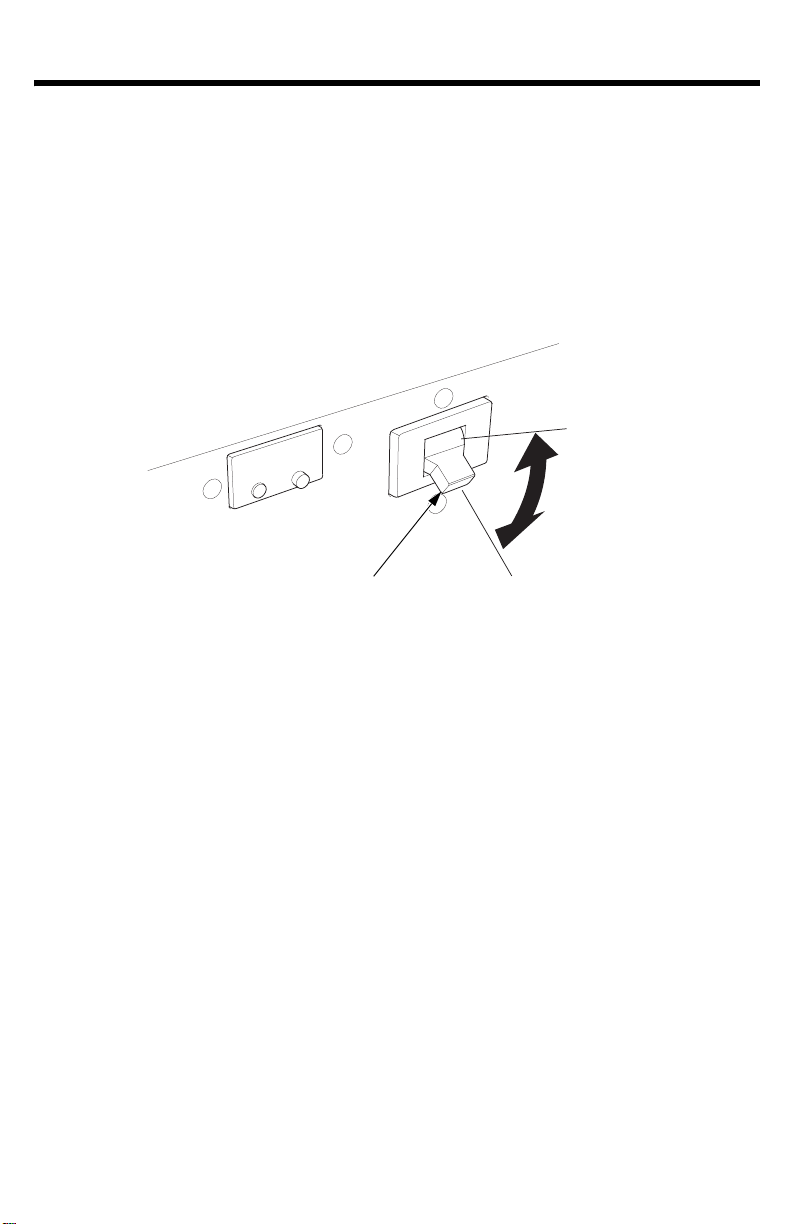
ENGINE SWITCH
OFF
ON
Direction to pull
STARTER GRIP
CONTROLS
Engine Switch
The engine switch controls the
ignition sy
stem.
OFF – Stops the engine.
ON – Running position, and for
starting.
St
arter Grip
Pulling the starter grip operates
ecoil starter to crank the
the r
engine.
• Do not allow the starter grip to
snap back against the generator.
Return it gently to prevent
damage to the starter.
• Do not let the starter rope rub
agains
t the generator body, or
the rope will wear out
prematurely.
• Be careful not to hit your hand
agains
t the handle when pulling
the starter grip.
12
CONTROLS & FEATURES
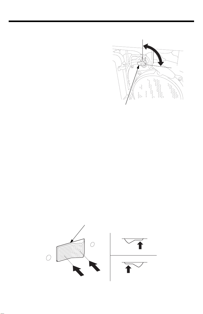
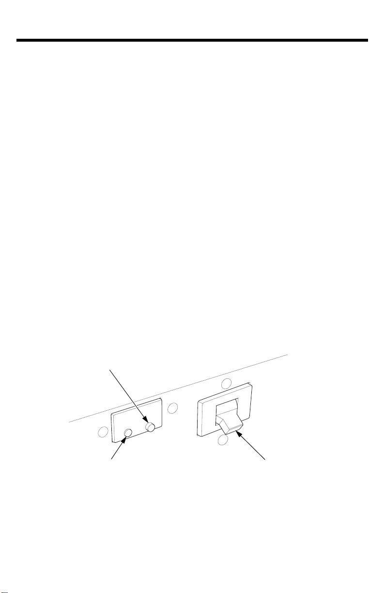
FUEL VALVE LEVER
OFF
ON
VOLTAGE SELECTOR SWITCH
120 V/240 V
120 V ONLY
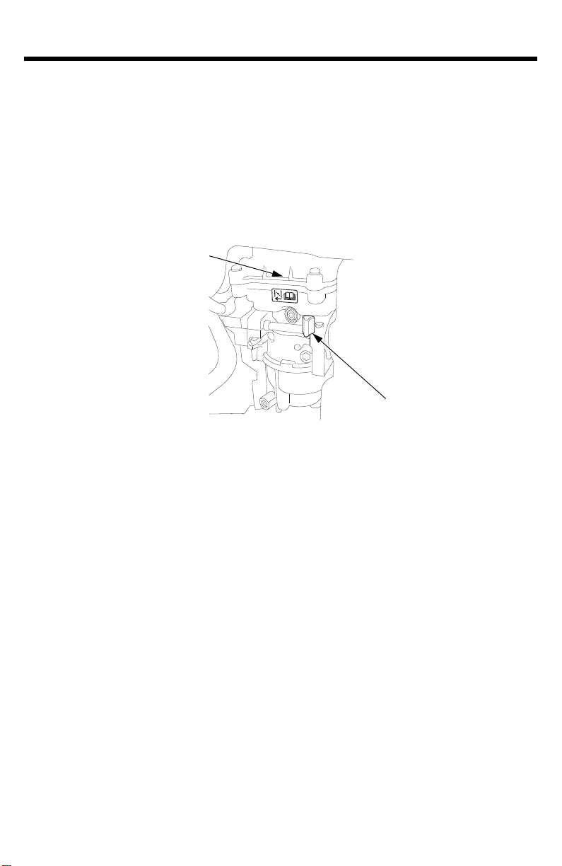
Fuel Valve Lever
The fuel valve lever is located
between the fuel tank and
carburetor.
The fuel valve must be in the ON
position fo
After stopping the engine, turn the
fue
valve to the OFF position.
l
Voltage Selector Switch
The voltage selector switch switches generator output to produce
‘‘120V ONL
the 4-prong receptacle, the switch must be in the ‘‘120V/240V’’
position. If only a 120V appliance is being connected to any of the
120V 3-prong receptacles, select the ‘‘120V ONLY’’ position.
Select the voltage before starting the engine.
r the engine to run.
Y’’ or ‘‘120V/240V.’’ If a 240V appliance is connected to
Switch Position
ecept
120V/240V: The 120V and 120V/240V r
acles can be used
simultaneously.
120V ONLY: ONLY 120 v
olts is available in this position; 240 volts is
not available. The most power will be available at the 30A 120V locking
plug receptacle.
13
CONTROLS & FEATURES
AUTO THROTTLE SWITCH
OFF
ON
ON
OFF
Auto Throttle® System
The Auto Throttle® system automatically reduces engine speed when all
loads are turned o
reconnected, the engine returns to the rated speed.
Switch Position
ff or disconnected. When appliances are turned on or
ON: Recommended
reduce noise levels when no load is applied to the generator.
OFF: The A
uto Throttle system does not operate.
Recommended to minimize warm-up time when the generator
is started
and when starting a load with large start-up power
equipments.
to minimize fuel consumption and further
14
CONTROLS & FEATURES
(4)120 V/240 V 20 A (EB4000X)
120 V/240 V 30 A (EB5000X,
EB6500X)
OFF
ON
AC CIRCUIT PROTECTOR for Receptacle (4)
AC CIRCUIT PROTECTOR for Receptacle (3)
AC CIRCUIT PROTECTOR
for Receptacle (2)
AC CIRCUIT PROTECTOR
for Receptacle (1)
(1) 120 V 30 A
(3) 120 V 20 A
PUSH
*: Except EB4000X
*
(2) 120 V 20 A
AC CIRCUIT PROTECTOR
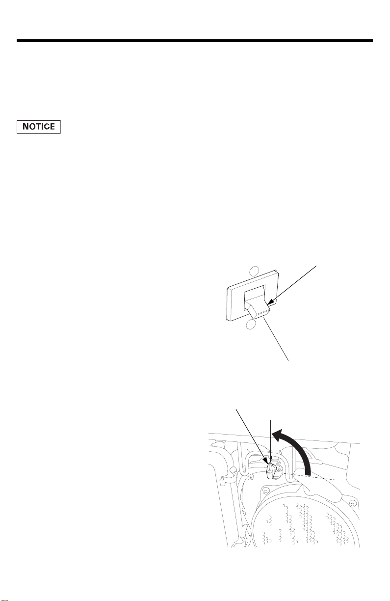
AC Circuit Protectors
The AC circuit protectors will automatically switch OFF if there is a
short circuit or a significant overload of the generator at each
receptacle. If an AC circuit protector switches OFF automatically, check
that the appliance is working properly and does not exceed the rated
load capacity of the circuit before resetting the AC circuit protector ON.
15
CONTROLS & FEATURES
OFF
ON
AC CIRCUIT BREAKER
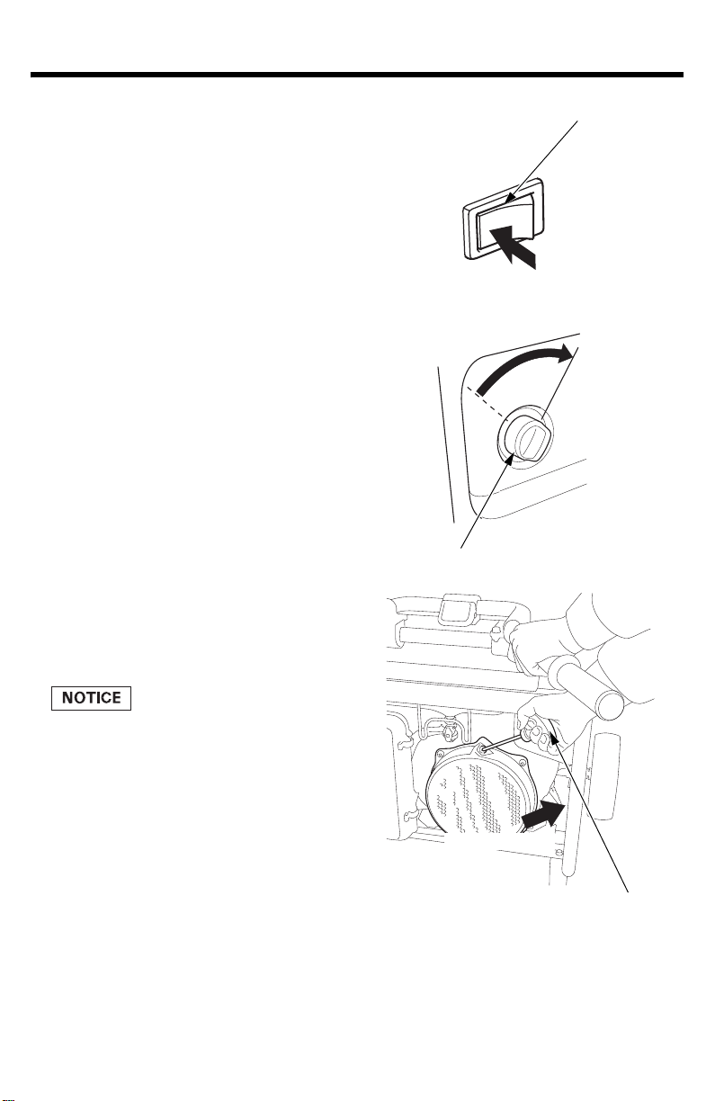
AC Circuit Breaker
The AC circuit breaker will automatically switch OFF if there is a short
uit or a significant overload at the receptacles, or if the ground fault
circ
circuit interrupter (GFCI) detects a ground fault current.
The AC circuit breaker may be used to switch the generator power ON
or OFF.
16
CONTROLS & FEATURES
GFCI TEST BUTTON
AC CIRCUIT BREAKER
GFCI RESET BUTTON
Ground Fault Circuit Interrupter (GFCI)
All receptacles on the generator are protected by a Ground Fault Circuit
Interrupter (GFCI) for protection against the shock hazard of ground
fault current. The GFCI has a TEST and RESET button and is connected
to the AC circuit breaker.
An example of ground-fault current is the current
that would flow
through a person who is using an appliance with faulty insulation and,
at the same time, is in contact with an electrical ground such as a
plumbing fixture, wet floor, or earth. The GFCI will protect against
current flowing through that person.
The GFCI will not protect against short circuit
s or overloads. The AC
circuit breaker and AC circuit protector provide that protection (see
pages 15 and 16).
GFCIs can be expected to interrupt power supply if there are ground
l
ts or stray current imposed on the wiring by other electrical
fau
devices, wiring, or equipment. As a result there is a risk of interruption
if used with critical systems such as life support equipment, so users
should first carefully consider whether it is appropriate to use this
portable generator to power such equipment.
17
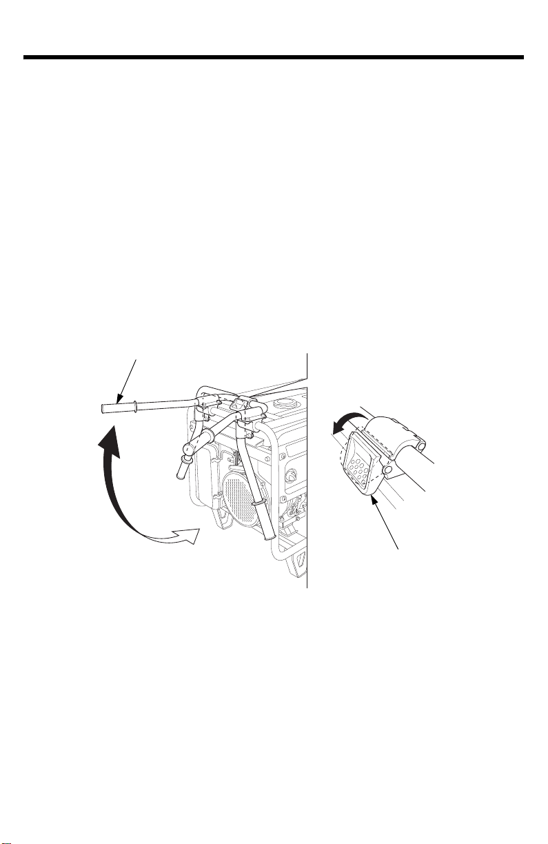
CONTROL & FEATURES
HANDLE
Handle
transport
position
Generator
stationary
position
HANDLE LOCK LEVER
Folding Handle
The foldable handle is intended for ease of transportation and should be
folded
extended handle.
To Extend The Handle
Lift handle upward. Lock lever will lock and secure the handle into
place.
when the generator is stationary. Do not rest objects on the
To Fold The
Handle
1.Press handle lock lever downward.
2.Lower the handle.
18

CONTROLS & FEATURES
FEATURES
Oil Alert® System
The Oil Alert® system is designed to prevent engine damage caused by
an insufficient amount of oil in the crankcase. Before the oil level in the
crankcase can fall below a safe limit, the Oil Alert system will
automatically stop the engine (the engine switch will remain in the ON
position).
If the engine stops and will not restart, check the engine oil level (see
page 45) before troubleshooting in other areas.
Automatic Engine Stop Function
Oil Alert
During
enough oil in the tank. Moreover, if the generator is on a slope, the oil
alert function may operate and stop the engine.
Overspeed Detection Function
To protect the engine from exceeding the engine load, the engine will
automatically stop if the engine speed becomes abnormal.
Abnormal Voltage Detection Function
The engine will automatically stop during generation when it detects
abnormal voltage.
If the engine stops, make sure the oil le
minutes, and then try to restart the engine. If the engine still won’t
start, take the generator to your authorized servicing Honda power
equipment dealer.
Function
operation, the engine will automatically stop if there is not
el is correct. Wait a few
v
19
CONTROLS & FEATURES
* ECM
MANUAL CHOKE LEVER
* ECM: Engine Control Module
Auto Choke and Throttle Control System
The ECM of this engine controls the choke valve and throttle
matically.
auto
When starting and warming up the engine, you do not need to operate
the chok
starting procedure.
e lever unless the engine is hard to start using the normal
iAVR (Intelligent Auto Voltage Regulator)
This generator is equipped with an intelligent, automatic voltage
regulat
or. The iAVR provides power in excess of the maximum rating for
up to ten seconds to start appliances that require high startup current.
The total amount of power available for each generator model is:
EB4000X: 5,000 watts for up to 10 seconds
EB5000X: 7,000 watts for up to 10 seconds
EB6500X: 7,000 watts for up to 10 seconds
20
CONTROLS & FEATURES
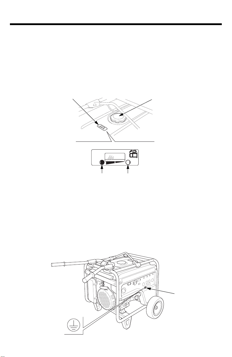
FUEL GAUGE
FUEL TANK CAP
EMPTYFULL
GROUND TERMINAL
Fuel Gauge
The fuel gauge is a mechanical device that measures the fuel level in
the tank. The red indicator in the window will reference the level in
relation to full or empty. To provide increased operating time, start with
a full tank before beginning operation. Check the fuel level with the
generator on a level surface. Always refuel with the engine OFF and
cool.
Ground Terminal
The generator ground terminal is connected to the frame of the
genera
tor, the metal non-current-carrying parts of the generator, and
the ground terminals of each receptacle.
Before using the ground terminal, consult a qualified electrician,
electrical inspector
, or local agency having jurisdiction for local codes or
ordinances that apply to the intended use of the generator.
21

BEFORE OPERATION
ARE YOU READY TO GET STARTED?
Your safety is your responsibility. A little time spent in pr
significantly reduce your risk of injury.
Knowledge
Read and u
to operate them.
Familiarize yourself with the generator and its operation before you
begin
emergency.
If the generator is being used to power appliances, be sure that they do
not ex
IS YOUR GENERATOR READY TO GO?
For your safety, to ensure compliance with environmental regulations,
and t
o
to take a few moments before you operate the generator to check its
condition. Be sure to take care of any problem you find, or have your
servicing dealer correct it, before you operate the generator.
nderstand this manual. Know what the controls do and how
using it. Know how to quickly shut off the generator in case of an
ceed the generator’s load rating (see page 33).
maximize the service life of your equipment, it is very important
eparation will
22
Improperly maintaining this
generator, or failing to correct a
problem before operation, could
cause a malfunction in which you
could be seriously injured.
Always perform a pre-operation
inspection bef
and correct any problem.
ore each operation,

BEFORE OPERATION
To prevent a possible fire, keep the generator at least 3 feet (1 meter)
away from building walls and other equipment during operation. Do not
place flammable objects close to the engine.
Before beginning your pre-operation checks, be sure the generator is on
a lev
el surface and the engine switch is in the OFF position.
Check the Engine
• Before each use, look around and underneath the engine for signs of
oil or gasoline leaks
• Check the oil level (see page 45). A low oil level will cause the Oil
Alert system to shut down the engine or prevent it from starting.
• Check the air cleaner (see page 48). A dirty air cleaner element will
restrict air flow to the carburetor, reducing engine and generator
per
ormance.
f
• Check the fuel level (see page 43). Starting with a full tank will help
to eliminate or reduce operating interruptions for refueling.
Check the GFCI
.
Check the GFCI operation (see page 29) after starting the engine.
23

OPERATION
SAFE OPERATING PRECAUTIONS
Before operating the generator for the first time, review chapters
GENERAT
).
22
For your safety, do not operate the generator in an enclosed area such
as a gara
monoxide gas that can collect rapidly in an enclosed area and cause
illness or death.
OR SAFETY (see page 6) and BEFORE OPERATION (see page
ge. Your generator’s exhaust contains poisonous carbon
Exhaust contains poisonous carbon
monoxide gas that can build up to
dangerous levels in closed areas.
Breathing carbon monoxide can
cause unconsciousness or death.
Never run the generator in a closed,
en partly closed area where
or ev
people may be present.
Before connecting an AC appliance or power cord to the generator:
• Use grounded 3-prong extension cords, tools, and appliances, or
e-insulated tools and appliances.
oubl
d
• Inspect cords and plugs, and replace if damaged.
• Do not use cord lengths greater than 164 feet (50 meters), and do
not use multiple t
use may activate the GFCI and trip the circuit breaker.
• Make sure that the appliance is in good working order. Faulty
appliances or
• Make sure the electrical rating of the tool or appliance does not
ex
ceed the rated power of the generator or the receptacle being used.
• Operate the generator at least 3 feet (1 meter) away from buildings
and other equ
• Do not operate the generator in an enclosed structure.
• Do not place flammable objects close to the engine.
ools and appliances with built-in noise filters. Such
wer cords can create a potential for electric shock.
po
ipment.
24
OPERATION
FUEL VALVE LEVER
OFF
AC CIRCUIT BREAKER
ON
STARTING THE ENGINE
To prevent a possible fire, keep the generator at least 3 feet (1 meter)
away from building walls and other equipment during operation. Do not
place flammable objects close to the engine.
Operating this generator less than 3 feet (1 meter) from a building or
ot
her obstruction can cause overheating and damage the generator. For
proper cooling, allow at least 3 feet (1 meter) of empty space above
and around the generator.
Refer to SAFE OPERATING PRECAUTIONS o
IS YOUR GENERATOR READY TO GO? ch
n page 24 and perform the
ecks (see page 22). Refer to
AC OPERATION (see page 31) for connecting loads to the generator.
1.Make sure that the AC circuit
er is in the OFF position.
break
The generator may be hard to
start if a load is connected.
2.Turn the fuel valve lever to the
ON position.
25
OPERATION
ENGINE SWITCH
OFF
AUTO THROTTLE SWITCH
ON
STARTER GRIP
Direction to pull
3.Make sure the Auto Throttle
switch is in the OFF position, or
more time will be required for
warm up.
4.Turn the engine switch to the
ON position.
Pull the starter grip lightly until
5.
o
u feel resistance; then pull
y
briskly in the direction of the
arrow as shown.
• Do not allow the starter grip
to
snap back against the
engine. Return it gently to
prevent damage to the starter.
• Do not let the starter rope rub
against the generator body, or
the rope will wear out
prematurely.
• Be careful not to hit your
hand against the handle when
pulling the starter grip.
26

6.If you wish to use the Auto
ON
AUTO THROTTLE SWITCH
Throttle system, turn the Auto
Throttle switch to the ON
position after the engine has
warmed up for 2 or 3 minutes.
OPERATION
27

OPERATION
OFF
AC CIRCUIT BREAKER
ENGINE SWITCH
OFF
FUEL VALVE LEVER
OFF
STOPPING THE ENGINE
To stop the engine in an emergency, si
mply turn the engine switch to
the OFF position. Under normal conditions, use the following procedure.
1.Turn off or disconnect all appliances that are connected to the
genera
tor.
2.Move the AC circuit breaker to
the OFF po
sition.
3.Turn the engine switch to the
OFF position.
Turn the fuel valve lever to the
4.
OFF po
sition.
28

OPERATION
GFCI RESET BUTTON
AC CIRCUIT BREAKER
GFCI TEST BUTTON
OFF
GFCI OPERATION CHECK
Always check GFCI operation before using the generator.
A faulty GFCI can cause electric
shock which can seriously injury or
kill you.
Always perform the GFCI inspection
o
re using the generator. If the
bef
GFCI fails the test, the generator
must be repaired by an authorized
Honda servicing dealer before use.
1.Unplug all tools and appliances from the generator.
2.Start the engine (see page 25).
3.Turn the AC circuit breaker to the ON position.
4.Turn OFF the Auto Throttle switch (see page 26).
5.Press the GFCI TEST button. The RESET button should extend, and
C circuit breaker should switch to the OFF position.
the A
If the GFCI and AC circuit breaker do not function as described, take
the
gener
ator to an authorized Honda generator dealer for repair.
29

OPERATION
GFCI RESET BUTTON
AC CIRCUIT BREAKER
ON
6.Press the GFCI RESET button. The RESET button should stay in, flush
with its base plate.
With the RESET button in and the engine running, turn the AC circuit
br
er to the ON position. The AC circuit breaker should remain in
eak
the ON position. The AC circuit breaker will not remain in the ON
position if the RESET button is extended.
If the GFCI and AC circuit breaker do not function as described, take
the gener
ator to an authorized Honda generator dealer for repair.
During generator use, if the GFCI RESET button extends and the AC
circuit br
eaker trips, this usually indicates a faulty power tool,
appliance, or cord.
ough
If that occurs, perform test steps 1 thr
6 to verify that the GFCI
and AC circuit breaker are in proper working order. If the GFCI and
AC circuit breaker test correctly, then you will know that the fault is
in the power tool, appliance, or cord. Repair or replace the faulty
power tool, appliance, or cord before further use.
30

OPERATION
120 V/240 V
VOLTAGE SELECTOR SWITCH
120 V ONLY
AC OPERATION
If an appliance begins to operate abnormally, becomes sluggish, or
stops suddenly, turn it off immediately. Disconnect the appliance, and
determine whether the problem is in the appliance or the rated load
capacity of the generator has been exceeded.
Substantial overloading may damage the generator. Marginal
erloading may shorten the service life of the generator.
ov
1.Turn the voltage selector switch to either position.
With the voltage selector switch in the ‘‘120V/240V’’ position, you
can use
are NOT using 240 volts, then select the ‘‘120V ONLY’’ position.
Disconnect or turn OFF all appliances or tools connected to the
generator before changing the voltage selector switch position.
The generator may be damaged if the switch position is changed with
loads connected and operating.
120V and 120V/240V receptacles simultaneously. If you
the
2.Start the engine (see page 25).
31

OPERATION
AC CIRCUIT PROTECTORS
AC CIRCUIT BREAKER
PLUG
*: Except EB4000X
*
ON
3.Switch ON the AC circuit breaker.
4.Plug in the appliance.
Most motorized appliances require more than their rated wattage for
startup.
Turn on the appliance.
5.
Do not exceed the current limit specified for any one receptacle. If an
erloaded circuit causes the AC circuit breaker or AC circuit protector
ov
to switch OFF, reduce the electrical load on the circuit, wait a few
minutes and then reset the AC circuit breaker or AC circuit protector.
If the generator is overloaded and the internal circuit is o
current to the connected appliance(s) may shut off, even though the AC
circuit breaker stays ON and the engine keeps running.
verheated,
Stop the engine and correct the problem. Allow the generator to cool
r a few minutes, and then restart the engine (see page 25).
fo
32

OPERATION
AC Applications
Before connecting an appliance or power cord to the generator:
• Make sure that it is in good working order. A faulty appliance or
power cord can create a potential for electrical shock.
• If an appliance begins to operate abnormally, becomes sluggish, or
stops sudd
and determine whether the problem is the appliance or the rated load
capacity of the generator has been exceeded.
Most appliance motors require more than their rated wattage for
startup.
Mak
e sure the electrical rating of the to
the maximum power rating of the generator.
Maximum power is:
EB4000X: 4.0 kVA
EB5000X: 5.0 kVA
EB6500X: 6.5 kVA
enly, turn it off immediately. Disconnect the appliance,
ol or appliance does not exceed
For continuous operation, do not exceed the rated power.
Rated power is:
EB4000X: 3.6 kVA
EB5000X: 4.5 kVA
EB6500X: 5.5 kVA
In either case, the total power requirements (VA) of all appliances
connected must be
manufacturers usually list rating information near the model number or
serial number.
Substantial overloading will open the circuit breaker. Slightly
overloading the generator may not switch the circuit breaker OFF, but
will shorten the service life of the generator.
considere
d. Appliance and power tool
33

OPERATION
(1)120 V 30 A
(2)120 V 20 A
(3)120 V 20 A
(4A)&(4B)120 V/240 V 20 A (EB4000X)
120 V/240 V 30 A (EB5000X, EB6500X)
*
*: Except EB4000X
POWER CIRCUIT A
120 V/240 V 120 V ONLY
POWER
CIRCUIT B
POWER
CIRCUIT A
POWER CIRCUIT B
AC Receptacle Selection
The control panel, shown below, has a voltage selector switch and four
recept
terminals, 4A and 4B.
acles. Receptacle 4, the 240-volt receptacle, has two powered
Power Producing Circuits
This generator is equipped with two power generating circuits.
When the voltage selector switch is in the 120V/240V position, each
of
the two power producing circuits supplies power to specific
receptacles.
When the voltage selector switch is in the 120V ONLY position, the
power producing circuits operate in parallel, sharing the total load
connected to terminal 4A and receptacles 1, 2, and 3.
34

OPERATION
Voltage Selector Switch
Disconnect or turn OFF all appliances or tools connected to the
generator before changing the voltage selector switch position.
The generator may be damaged if the switch position is changed with
loads connected and operating.
The power available to each receptacle depends on the position of the
voltage selector switch.
Switch
Position
120V ONLY 1 30A at 120V 30A at 120V 30A at 120V
120V/240V 1
120V ONLY Position
When the vo
not need to spread the load over the receptacles. You must, however,
make sure the load on any receptacle does not exceed its available
power shown in the table above and the total load does not exceed the
total current available.
Receptacle
2 20A at 120V 20A at 120V 20A at 120V
3 20A at 120V 20A at 120V 20A at 120V
4A 20A at 120V 30A at 120V 30A at 120V
4B None None None
2
3
4A-4B
ltage selector switch is in the 120V ONLY position, you do
EB4000X EB5000X EB6500X
15.0A at 120V 18.8A at 120V 22.9A at 120V
15.0A at 120V 18.8A at 120V
15.0A at 120V 18.8A at 120V
15.0A at 240V 18.8A at 240V 22.9A at 240V
Available Power
20A at 120V
20A at 120V
Total Current Available:
30.0 A (EB4000X)
A (EB5
37.5
45.8 A (EB6500X)
000X)
35

OPERATION
120V/240V Position
When the voltage selector switch is in the 120V/240V position, you
must balance the load. Divide the load between the two sets of
receptacles shown below. Balancing is necessary because each set of
receptacles is powered by only one power producing circuit that can
produce a maximum of amps(*).
*:
15.0 A (EB4000X)
18.8 A (EB5
22.9 A (EB6500X)
000X)
Set of
Receptacles
1+3+4B 15.0A 18.8A 22.9A B
2+4A 15.0A 18.8A 22.9A A
Total Current Available
EB4000X EB5000X EB6500X
Power Producing
Circuit
36

OPERATION
AUTO THROTTLE SWITCH
OFF
OFF
ON
ON
AUTO THROTTLE® SYSTEM
With the switch in the ON position, engine speed is automatically
reduced when ALL loads are turned OFF or disconnected. When
appliances are turned ON or reconnected, the engine returns to rated
speed. In the OFF position, the Auto Throttle system does not operate.
The Auto Throttle system will not respond to electrical loads of less
than 1 ampere or intermittent loads such as a staple gun. Turn the Auto
Throttle switch to the OFF position to operate loads of less than 1 amp.
Appliances with large start-up power demands may not allow the
engine
generator. Push the Auto Throttle switch to the OFF position and
connect the appliance to the generator. If the engine still will not reach
normal operating speed, check that the appliance does not exceed the
rated load capacity of the generator.
To avoid extended warm-up periods, keep the switch OFF until the
engin
to reach normal operating rpm when they are connected to the
e
reaches operating temperature.
The Auto Throttle system is not effective f
or use with appliances that
require only momentary power. If the tool or appliance will be turned
ON and OFF quickly, the Auto Throttle switch should be in the OFF
position.
37

OPERATION
STANDBY POWER
Connections to a Building’s Electrical System
Connections for standby power to a building’s electrical system must
be made by
generator power from utility power, and must comply with all applicable
laws and electrical codes.
a qualified electrician. The connection must isolate the
Improper connections to a building’s
electrical system can allow current
from the generator to backfeed into
the utility lines.
Such backfeed may electrocute
utility compan
who contact the lines during a
power outage, and the generator
may explode, burn, or cause fires
when utility power is restored.
y workers or others
Consult the utility company or a
fied e
quali
any power connections.
In some areas, generators are required by law to be registered with local
utility companies
use procedures.
System Ground
This generator has a system ground that connects generator frame
components to ground terminals in the AC output receptacles. The
system grou
. Check local regulations for proper registration and
nd is co
nnected to the AC neutral wire.
lectrician prior to making
38

OPERATION
Special Requirements
There may be Federal or State Occupational Safety and Health
Administration (OSHA) regulations, local codes, or ordinances that
apply to the intended use of the generator. Please consult a qualified
electrician, electrical inspector, or the local agency having jurisdiction.
• In some areas, generators are required to be registered with local
utility companies.
If the generator is used at a construction site, there may be additional
•
regulations that must be observed.
39

SERVICING YOUR GENERATOR
THE IMPORTANCE OF MAINTENANCE
Good maintenance is essential for safe, economical, and trouble free
operation. It will
To help you properly care for your generator, the following pages
include a mai
simple maintenance procedures using basic hand tools. Other service
tasks that are more difficult or require special tools are best handled by
professionals and are normally performed by a Honda technician or
other qualified mechanic.
The maintenance schedule applies to normal operating conditions. If
yo
u operate your generator under unusual conditions, such as sustained
high-load or high-temperature operation, or use it in dusty conditions,
consult your servicing dealer for recommendations applicable to your
individual needs and use.
also help reduce air pollution.
ntenance schedule, routine inspection procedures, and
Improper maintenance, or failure to
correct a problem before operation,
can cause a malfunction in which
you can be seriously hurt or killed.
Always follow the inspection and
maintenance r
schedules in this owner’s manual.
Remember that an authorized Honda servicing dealer know
generator best and is fully equipped to maintain and repair it.
To ensure the best quality and reliability, use only ne
parts or their equivalents for repair and replacement.
Maintenance, replacement, or repair of the emission control devices
systems may be performed by any engine repair establishment or
and
individual, using parts that are ‘‘certified’’ to EPA standards.
ecommendations and
s your
w, Honda Genuine
40

SERVICING YOUR GENERATOR
MAINTENANCE SAFETY
Some of the most important safety precautions follow. However, we
cannot warn you of every conceivable hazard that can arise in
performing maintenance. Only you can decide whether or not you
should perform a given task.
Failure to properly follow
maintenance instructions and
precautions can cause you to be
seriously hurt or killed.
Always follow the procedures and
precautions
Safety Precautions
Make sure the engine is off before you begin any maintenance or
s. This will eliminate several potential hazards:
repair
in the owner’s manual.
– Carbon monoxide poisoning from engine exhaust.
Operate outside away from open windows or doors.
– Burns from hot parts.
Let the engine and exhaust system cool before touching.
– Injury from moving parts.
Do not run the engine unless instructed to do so.
• Read the instructions before you begin, and make sure you have the
ols and skills required.
o
t
• To reduce the possibility of fire or explosion, be careful when working
around
clean parts. Keep cigarettes, sparks, and flames away from all fuelrelated parts.
gasoline. Use only a non-flammable solvent, not gasoline, to
41

SERVICING YOUR GENERATOR
REGULAR SERVICE PERIOD (3)
Perform at every indicated month
or operating hour interval,
whichever comes first.
ITEM
MAINTENANCE SCHEDULE
Each
use
Engine oil Check level o 45
Air cleaner Check o 48
GFCI operation Check o 29
Sediment cup Clean o 54
Spark plug Check-adjust o 51
Spark arrester Clean o 53
Valve clearance Check-adjust o (2) —
Combustion
chamber
Fuel tank and filter Clean o (2) —
Fuel tube Check Every 2 years (Replace if necessary) (2) —
Canister Check Every 2 years (Replace if necessary) (2) —
Purge tube Check Every 2 years (Replace if necessary) (2) —
Charge tube Check Every 2 years (Replace if necessary) (2) —
(1) Service more frequently when used in dusty areas.
(2) These items should be serviced by your servicing dea
are mechanically proficient. Refer to the Honda shop manual for service procedures.
See “Honda Publications” on page 72 for ordering information.
(3) For commercial use, log hours of operation to determine proper maintenance intervals.
Failure to follow this maintenance schedule could result in non-warrantable failures.
Change o o 46
Clean o (1) 50
Replace o 51
Clean
First
month
20 Hrs.
After every 1,000 Hrs. (2) —
Every
months
or
or
50 Hrs.
ler, unless you have the proper tools and
Every
3
months
100 Hrs.
Every
6
or
year
or
300 Hrs.
Pag e
42

SERVICING YOUR GENERATOR
REFUELING
With the engine stopped, check the fuel gauge. Refill the fuel tank if the
fuel level is low.
Gasoline is highly flammable and
explosive.
You can be burned or seriously
injured when handling fuel.
Stop the engine and keep heat,
•
sparks
• Handle fuel only outdoors.
• Wipe up spills immediately.
Fuel can damage paint and plastic. Be careful not to spill fuel when
ing yo
fill
under warranty.
ur fuel tank. Damage caused by spilled fuel is not covered
, and flame away.
Refuel in a well-ventilated area before starting th
has been running, allow it to cool. Refuel carefully to avoid spilling fuel.
Do not fill above the upper level mark.
Never refuel the engine inside a building where gasoline fumes may
reach flames or sparks.
barbecues, electric appliances, power tools, etc.
Spilled fuel is not only a fire hazard, it causes environmental damage.
Wipe up spills imme
Keep gasoline away from appliance pilot lights,
diately.
e engine. If the engine
43

SERVICING YOUR GENERATOR
FUEL LEVEL GAUGE
FUEL TANK CAP
UPPER LEVEL MARK (RED)
FUEL FILTER
UPPER LEVEL MARK (RED)
EMPTYFULL
After refueling, reinstall the fuel tank cap securely.
FUEL RECOMMENDATIONS
This engine is certified to operate on r
egular unleaded gasoline with a
pump octane rating of 86 or higher.
Never use stale or contaminated gasoline or an oil/gasoline mixture.
oid getting dirt or water in the fuel tank.
Av
You may use regular unleaded gasoline containing no more than 10%
ethanol (
contain cosolvents and corrosion inhibitors.
E10) or 5% methanol by volume. In addition, methanol must
Use of fuels with content of ethanol or methanol greater than shown
e may cause starting and/or performance problems. It may also
v
abo
damage metal, rubber, and plastic parts of the fuel system.
Engine damage or performance problems that result from using a fuel
cent
with per
ages of ethanol or methanol greater than shown above are
not covered under warranty.
If your equipment will be used on an infrequent or intermittent basis
please refer to the fuel section of the STORAGE chapter (see page 55)
for additional information regarding fuel deterioration.
44
,

SERVICING YOUR GENERATOR
OIL FILLER CAP/DIPSTICK
UPPER LIMIT
FILLER NECK
ENGINE OIL LEVEL CHECK
Check the oil level BEFORE EACH USE with the generator on a level
surface and the engine stopped.
1.Remove the oil filler cap/dipstick and wipe it clean.
2.Insert and remove the dipstick without scre
wing it into the filler neck.
Check the oil level shown on the dipstick.
3.If the oil level is low, fill to the upper limit mark on the dipstick with
ecommended oil (see page 47).
the r
4.Reinstall the oil filler cap/dipstick securely.
The Oil Alert system will automatically stop the engine before the oil
el falls below safe limits. However, to avoid the inconvenience of an
lev
unexpected shutdown, check the oil level regularly.
45

SERVICING YOUR GENERATOR
SEALING
WASHER
(Replace)
12×15 mm
OIL DRAIN PLUG
OIL FILLER CAP/DIPSTICK
UPPER LIMIT
ENGINE OIL CHANGE
Drain the oil while the engine is warm to assure rapid and complete
ing.
drain
1.Place a suitable container below the engine to catch the used oil, and
remove the oil filler cap/dipstick, 12×15 mm drain plug, and
then
sealing washer.
2.Allow the used oil to drain completely, and then r
einstall the 12×15
mm drain plug and a new sealing washer. Tighten the plug securely.
3.With the generator in a level position, fill to the upper limit mark on
the
dipstick with the r
Maximum oil capacity: 1.2
ecommended oil (see page 47).
US qt (1.1
L)
4.Reinstall the oil filler cap/dipstick securely.
Wash your hands with soap and water after handling used oil.
Improper disposal of engine oil can be harmful to the environment. If
you change y
container, and take it to a recycling center. Do not discard it in a trash
bin, dump it on the ground, or pour it down a drain.
46
our own oil, please dispose of it properly. Put it in a sealed

SERVICING YOUR GENERATOR
AMBIENT TEMPERATURE
ENGINE OIL RECOMMENDATIONS
Oil is a major factor affecting performance and service life. Use
4-stroke automotive detergent oil.
SAE 10W–30 is recommended for general use. Other viscosities shown
in the chart ma
within the recommended range.
y be used when the average temperature in your area is
The SAE oil viscosity and service category are in th
container. Honda recommends that you use API service category SJ or
later (or equivalent) oil.
e API label on the oil
47

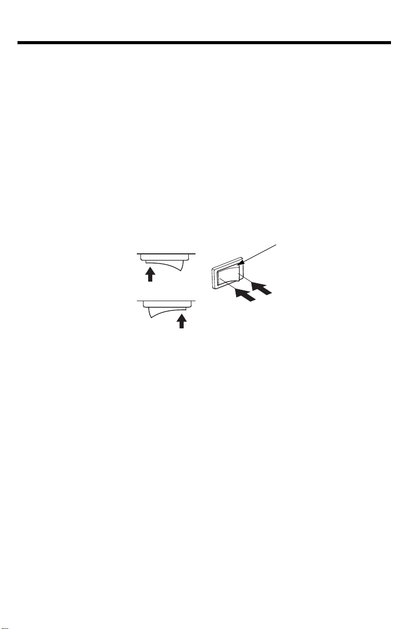
SERVICING YOUR GENERATOR
HOOK
AIR CLEANER CASE
SETTING PIN
AIR CLEANER COVER
AIR CLEANER ELEMENT
FRAME PIPE
CLIP
AIR CLEANER SERVICE
1.Unsnap the air cleaner cover clips and open the air cleaner cover.
2.Free the hooks from the setting pins on the air cleaner case and
ve the air cleaner cover to the right side of the frame pipe, taking
remo
care not to damage the air cleaner cover.
3.Remove the air cleaner element from the air cleaner case.
4.Check the air cleaner element to be sure it is clean and in good
condition.
If the air cleaner element is dirty, clean it as described on page 50.
Replace the air cleaner element if it is damaged.
48

SERVICING YOUR GENERATOR
GOOD NO GOOD
HOOK
AIR CLEANER CASE
SETTING PIN
AIR CLEANER COVER
AIR CLEANER ELEMENT
CLIP
5.Reinstall the air cleaner element in the air cleaner case.
6.Set the hooks of the air cleaner cover to the setting pins securely,
and then push
Be sure that the cover is set securely. There must be no clearance
between the air cleaner co
Operating the engine without an air filter or with a damaged air filter
will allow dirt
of damage is not covered by the Distributor’s Limited Warranty.
the air cleaner cover to lock the clips.
ver and air cleaner case.
to enter the engine, causing rapid engine wear. This type
49

SERVICING YOUR GENERATOR
Clean Squeeze and Dry
Do not twist.
Dip in Oil
Squeeze
Do not twist.
AIR CLEANER ELEMENT CLEANING
A dirty air cleaner element will restrict air flow
reducing engine performance. If you operate the generator in very dusty
areas, clean the air cleaner element more frequently than specified in
the Maintenance Schedule.
1.Wash the air cleaner element in a solution of household detergent
and w
high flashpoint solvent. Allow the air cleaner element to dry
thoroughly.
2.Soak the air cleaner element in clean engine oil and squeeze out the
ex
is left in the air cleaner element.
arm water and rinse thoroughly, or wash in nonflammable or
cess oil. The engine will smoke during initial startup if too much oil
to the carburetor,
3.Wipe dirt from the air cleaner housing and cover using a moist rag. Be
careful t
carburetor.
o prevent dirt from entering the air duct that leads to the
50

SERVICING YOUR GENERATOR
SPARK PLUG WRENCH
SPARK PLUG CAP
SPARK PLUG SERVICE
In order to service the spark plug, you will need a spark plug wrench
(commercially available).
Recommended spark plugs: BPR5ES
W16EPR-U (DENSO)
To ensure proper engine operation, the spark plug must be properly
gapped and free o
An incorrect spark plug can cause engine damage.
If the engine is hot, allow it to cool befo
1.Disconnect the spark plug cap, and remove any dirt from around the
spark plug area.
Remove the spark plug with a spark plug wrench.
2.
f deposits.
(NGK)
re servicing the spark plug.
51

SERVICING YOUR GENERATOR
SIDE ELECTRODE
0.028–0.031 in (0.7–0.8 mm)
SEALING WASHER
INSULATOR
3.Visually inspect the spark plug. Replace it if the electrodes are worn
or if the insulator is cracked, chipped, or fouled.
4.Measure the spark plug electrode gap with a wire-type feeler gauge.
Correct the gap, if necessary, by carefully bending the side electrode.
The gap should be:
0.028–0.031 in (0.7–0.8 mm)
5.Check that the spark plug sealing washer is in good condition, and
threa
d the spark plug in by hand to prevent cross-threading.
6.After the spark plug is seated, tighten with a spark pl
ug wr
ench to
compress the washer.
If installing a new spark plug, tighten 1/2 turn after the spark plug
seats to compress the washer. If reinstalling a used spark plug,
tighten 1/8–1/4 turn after the spark plug seats to compress the
washer.
A loose spark plug can overheat and damage the engine.
Overtigh
tening the spark plug can damage the threads in the cylinder
head.
7.Attach the spark plug cap.
52

SERVICING YOUR GENERATOR
SPARK ARRESTER
5 mm SCREWS
SPARK ARRESTER SCREEN
SPARK ARRESTER SERVICE
The spark arrester must be serviced every 100 hours to keep it
functioning as designed.
If the engine has been running, the muffler will be very hot.
Allow the
muffler to cool before servicing the spark arrester.
Clean the spark arrester as follows:
1.Remove the two 5 mm screws, and remove the spark arrester.
2.Use a brush to remove carbon deposits from the spark arrester
een.
scr
Be car
The spark arrester must be free of
eful to avoid damaging the screen.
breaks and tears. Replace the
spark arrester if it is damaged.
3.Install the spark arrester in the reverse order of removal.
53

SERVICING YOUR GENERATOR
FUEL VALVE LEVER
OFF
O-RING
(Replace)
SEDIMENT CUP
SEDIMENT CUP CLEANING
The sediment cup prevents dirt or water that may be in the fuel tank
m entering the carburetor. If the engine has not been run for a long
fro
time, the sediment cup should be cleaned.
1.Turn the engine switch to the OFF position.
Gasoline is highly flammable and
explosive.
You can be burned or seriously
injured when handling fuel.
Stop the engine and keep heat,
•
sparks
• Handle fuel only outdoors.
• Wipe up spills immediately.
, and flame away.
2.Turn the fuel valve lever to the
OFF po
sition;
then remove the
sediment cup and the O-ring.
Discard the O-ring.
3.Clean the sediment cup in
nonflammable solvent, and dry
it thor
oughly.
4.Install the sediment cup and a
new O-ring,
and tighten the
sediment cup securely.
5.Turn the fuel valve lever to the
ON position
and check f
or leaks.
54

STORAGE
STORAGE PREPARATION
Proper storage preparation is essential for keeping your generator
uble-free and looking good. The following steps will help to keep rust
tro
and corrosion from impairing your generator’s function and appearance,
and will make the engine easier to start when you use the generator
again.
Cleaning
Wipe the generator with a moist cloth. After the generator has dried,
ouch
up any damaged paint, and coat other areas that may rust with a
t
light film of oil.
Fuel
Dependi
formulations may deteriorate and oxidize rapidly. Fuel deterioration and
oxidation can occur in as little as 30 days and may cause damage to
the carburetor and/or fuel system. Please check with your servicing
dealer for local storage recommendations.
Gasoline will oxidize and deteriorate in storage. Old gasoline will cause
hard
the gasoline in your generator deteriorates during storage, you may
need to have the carburetor and other fuel system components serviced
or replaced.
The length of time that gasoline can be left in your fuel tank and
carbur
factors as gasoline blend, your storage temperatures, and whether the
fuel tank is partially or completely filled. The air in a partially filled fuel
tank promotes fuel deterioration. Very warm storage temperatures
accelerate fuel deterioration. Fuel deterioration problems may occur
within a few months, or even less if the gasoline was not fresh when
you filled the fuel tank.
The Distributor’s Limited Warranty does not
or engine performance problems resulting from neglected storage
preparation.
You can extend fuel storage life by adding a gasoline stabilizer that is
rmulated for that purpose, or you can avoid fuel deterioration
fo
problems by draining the carburetor, sediment cup, and/or fuel tank.
ng on th
starting, and it leaves gum deposits that clog the fuel system. If
et
or without causing functional problems will vary with such
e region where you operate your equipment, fuel
cover fuel system damage
55

STORAGE
Service according to the table below:
STORAGE TIME RECOMMENDED SERVICE PROCEDURE TO
PREVENT HARD STARTING
Less than 1 mo nth No preparation required
1 to 2 months
2 months to 1 year
1 year or more
* Use gasoline stabilizers that are formulated to extend storage
Follow the manufacturer’s instructions for use.
Contact your authorized Honda generator dealer for stabilizer
recom
mendations.
Fill with fresh gasoline and add gasoline
stabilizer *.
Fill with fresh gasoline and add gasoline
stabilizer *.
Drain the carburetor float bowl (see page 57).
Drain the fuel sediment cup (see page 54).
Fill with fresh gasoline and add gasoline
stabilizer *.
Drain the carburetor float bowl (see page 57).
Drain the fuel sediment cup (see page 54).
Remove the spark plug. Put a teaspoon of engine
oil into
the pull rope to distribute the oil.
Reinstall the spark plug.
Change the engine oil (see page 46).
After removal from storage, drain the stored
gasoline into a suitable container,
fresh gasoline before starting.
the cylinder.
Turn the engine slowly with
and fill with
life.
56

STORAGE
CARBURETOR DRAIN SCREW
Draining the Fuel Tank and Carburetor
Gasoline is highly flammable and
explosive.
You can be burned or seriously
injured when handling fuel.
Stop the engine and keep heat,
•
sparks
• Handle fuel only outdoors.
• Wipe up spills immediately.
1.Turn the fuel valve lever to the OFF position.
2.Place a suitable gasoline container below the carburetor, and use a
funnel to
avoid spilling fuel.
, and flame away.
3.Loosen the carburetor drain screw and drain the gasoline from the
carburet
or.
57

STORAGE
FUEL VALVE LEVER
ON
4.After all the gasoline has drained into the container, tighten the
carburetor drain screw securely.
5.Place a suitable gasoline container below the sediment cup, and use
a funnel
6.Remove the sediment cup (see page 54), and then turn the fuel valve
lever to the ON position and drain the fuel from the fuel tank.
7.After all the fuel tank has drained into the container, install the
sediment cup
8.Turn the fuel valve lever to the OFF position.
o avoid spilling gasoline.
t
and
a new O-ring.
Engine Oil
1.Change the engine oil (see page 46).
2.Remove the spark plug, and pour one teaspoon (5 cc) of clean engine
oil int
the oil, then reinstall the spark plug.
3.Slowly pull the starter grip until resist
piston is coming up on its compression stroke, and both the intake
and exhaust valves are closed. Storing the engine in this position will
help to protect it from internal corrosion.
the cylinder. Crank the engine several revolutions to distribute
o
ance
is felt. At this point, the
58

STORAGE
STORAGE PRECAUTIONS
If your generator will be stored with gasoline in the fuel tank and
carburetor, it is important to reduce the hazard of gasoline vapor
ignition.
Select a well ventilated storage area away from any appliance that
operates with
Also avoid any area with a spark-producing electric motor, or where
power tools are operated.
a flame, such as a furnace, water heater, or clothes dryer.
If possible, avoid storage areas with high humidity,
promotes rust and corrosion.
Unless all fuel has been drained from the fuel tank, leave the engine
switch in
(see page 28) to reduce the possibility of leakage.
Place the generator on a level surface. Tilting or laying it on its side can
cause fuel or oil leakage
With the engine and exhaust system cool, cover the generator to keep
out dust. A ho
materials.
Do not use sheet plastic as a dust cov
moisture around the generator, promoting rust and corrosion.
REMOVAL FROM STORAGE
Check y
of this manual (see page 22).
If the generator was stored for 1 year or longer, drain the fuel tank (see
page 57) and refuel with fresh gasoline. If you keep a container of
gasoline for refueling, be sure that it contains only fresh gasoline.
Gasoline ox
the OFF position, and the fuel valve lever in the OFF position
.
gine and exhaust system can ignite or melt some
t en
er. A nonporous cover will trap
our generator as described in the BEFORE OPERATION chapter
idizes and deteriorates over time, causing hard starting.
because that
If the cylinder was coated with oil during storage preparation, the
engine
may smoke briefly at startup. This is normal.
59

TRANSPORTING
HANDLE BAR
LIFTING HANGER
Do not lay the generator on its side when moving, storing, or operating
it. Oil or fuel may leak and damage the engine or your property.
If the generator has been running, allow the engine to cool for at least
nutes before loading the generator on the transport vehicle. A hot
15 mi
engine and exhaust system can burn you and can ignite some materials.
Keep the generator level when transporting to
fuel leakage. Move the fuel valve lever to the OFF position. Do not use
the generator while it is being transported.
When using ropes or tie-down straps to secure the generator for
tran
sportation, be sure to only use the frame bars as attachment points.
Do not fasten ropes or straps to any portions of the generator body or
handle bar.
To lift the generator
Lift the generator by the lifting hanger. Do not try to lift the generator
by
any other part.
reduce the possibility of
60

TAKING CARE OF UNEXPECTED PROBLEMS
ENGINE WILL NOT START
Possible Cause Correction
Fuel valve lever OFF. Turn lever ON (see page 25).
Engine switch OFF. Turn engine switch to ON
(see page 26).
Out of fuel. Refuel (see page 43).
Bad fuel; generator stored without
treating
refueled with bad gasoline.
Low oil level caused Oil Alert to
stop en
Spark plug faulty, fouled, or
improperly gapp
Spark plug wet with fuel
(flooded engine).
Fuel filter restricted, carburetor
malfunction, ignition m
valves stuck, etc.
or draining gasoline, or
gine.
ed.
alfunction,
Drain fuel tank and carburetor
(see page 57).
Refuel with fresh gasoline
(see page 43).
Add oil (see page 45).
Turn engine switch to OFF and
then r
estart the engine.
Gap or replace spark plug
(see page 52).
Dry and reinstall spark plug.
Take the generator to an
authorized Honda servicing dealer,
or re
fer to the shop manual.
61

TAKING CARE OF UNEXPECTED PROBLEMS
ENGINE LACKS POWER
Possible Cause Correction
Air filter restricted. Clean or replace air filter
(see pages 48, 49, 50).
Bad fuel; generator stored without
treating
refueled with bad gasoline.
Fuel filter restricted, carburetor
malfunction, ignition m
valves stuck, etc.
or draining gasoline, or
alfunction,
Drain fuel tank and carburetor
(see page 57).
Refuel with fresh gasoline
(see page 43).
Take the generator to an
authorized Honda servicing dealer,
fer to the shop manual.
or re
62

TAKING CARE OF UNEXPECTED PROBLEMS
NO POWER AT THE AC RECEPTACLES
Possible Cause Correction
AC circuit breaker left in the OFF
position after star
GFCI activated. Test GFCI (see page 29) and reset
AC circuit protector tripped. Check AC load and reset circuit
Faulty power tool or appliance. Replace or repair power tool or
Internal circuit overheated. Stop the engine. Reduce the
Faulty generator. Take the generator to an
ting.
Check AC load and reset AC
circuit breaker (see page 32).
AC circuit breaker.
Replace faulty power tool or
appliance.
protector (s
appliance.
Stop and restart the engine.
electrical
for the internal circuit to cool
down. Restart the engine.
authorized Honda servicing dealer,
or refer to the shop manual.
ee page15).
load.
Wait a few minutes
63

TECHNICAL INFORMATION
FRAME SERIAL NUMBER
ENGINE SERIAL NUMBER
Serial Number Location
Record the frame serial number and date purchased in the spaces
. You will need this information when ordering parts and when
below
making technical or warranty inquiries.
Engine serial number:
Frame serial number:
Date purchased:
64

TECHNICAL INFORMATION
Carburetor Modification for High Altitude Operation
At high altitude, the standard carburetor air-fuel mixture will be too rich.
Performance will decrease, and fuel consumption will increase. A very
rich mixture will also foul the spark plug and cause hard starting.
Operation at an altitude that differs from that at which this engine was
certified, for extended periods of time, may increase emissions.
High altitude performance can be improved by specific modifications to
the carbur
5,000 feet (1,500 meters), have your authorized Honda servicing
dealer perform this carburetor modification. This engine, when operated
at high altitude with the carburetor modifications for high altitude use,
will meet each emission standard throughout its useful life.
Even with carburetor modification, engine horsepower will decrease
about 3.5%
effect of altitude on horsepower will be greater than this if no
carburetor modification is made.
When the carburetor has been modified for high altitude operation, the
air/fuel mixture will be too lean for low altitude use. Operation at
altitudes below 5,000 feet (1,500 meters) with a modified carburetor
may cause the engine to overheat and result in serious engine damage.
For use at low altitudes, have your servicing dealer return the carburetor
to original factory specifications.
etor. If you always operate your generator at altitudes above
for each 1,000-foot (300-meter) increase in altitude. The
65

TECHNICAL INFORMATION
Emission Control System Information
Source of Emissions
The combustion process produces carbon monoxide, oxides of nitrogen,
ydrocarbons. Control of hydrocarbons and oxides of nitrogen is
and h
very important because, under certain conditions, they react to form
photochemical smog when subjected to sunlight. Carbon monoxide
does not react in the same way, but it is toxic.
Honda utilizes appropriate air/fuel ratios and other emissions control
stems to reduce the emissions of carbon monoxide, oxides of
sy
nitrogen, and hydrocarbons.
Additionally, Honda fuel systems utilize components and control
technologies to
The U.S. and California Clean Air Acts
EPA and California regulations require all manufacturers to furnish
written instruction
emission control systems.
reduce evaporative emissions.
s describing the operation and maintenance of
The following instructions and procedures must be followed in order to
keep the Ho
Tampering and Altering
Tampering is a violation of Federal and California law.
Tampering with or altering the emission control system may increase
emissions b
tampering are:
• Removal or alteration of any part of intake, fuel, or exhaust systems.
• Altering or defeating the governor linkage or speed-adjusting
mechanism
parameters.
nda engine emissions within the emission standards.
eyond the legal limit. Among those acts that constitute
t
o cause the engine to operate outside its design
66

TECHNICAL INFORMATION
Problems That May Affect Emissions
If you are aware of any of the following symptoms, have your engine
inspected and repaired by your authorized Honda servicing dealer.
• Hard starting or stalling after starting.
• Rough idle.
• Misfiring or backfiring under load.
• Afterburning (backfiring).
• Black exhaust smoke or high fuel consumption.
Replacement Parts
The emission control systems on your new Honda engine were
designed
regulations. We recommend the use of Honda Genuine parts whenever
you have maintenance done. These original-design replacement parts
are manufactured to the same standards as the original parts, so you
can be confident of their performance. The use of replacement parts
that are not of the original design and quality may impair the
effectiveness of your emission control system.
, built, and certified to conform with applicable emission
A manufacturer of an aftermarket part assumes the responsibility that
part will not adv
the
manufacturer or rebuilder of the part must certify that use of the part
will not result in a failure of the engine to comply with emission
regulations.
Maintenance
Follow the MA
this schedule is based on the assumption that yo
used for its designed purpose. Sustained high-load or high-temperature
operation, or use in dusty conditions, will require more frequent service.
ersely affect emission performance. The
INTENANCE SCHEDULE on page 42. Remember that
ur machine will be
67

TECHNICAL INFORMATION
Air Index
An Air Index Information label is applied to engines certified to an
emission dur
the California Air Resources Board.
The bar graph is intended to provide you, our customer, the ability to
compare
Air Index, the less pollution.
The durability description is intended to provide you with information
relating t
indicates the useful life period for the engine’s emission control system.
See your Emission Control System Warranty for additional information.
Descriptive Term Applicable to Emission Durability Period
der
Mo
Intermediate 125 hours (0—80 cc, inclusive)
Extended 300 hours (0—80 cc, inclusive)
ability time period in accordance with the requirements of
the emissions performance of available engines. The lower the
o the engine’s emission durability period. The descriptive term
ate 50 hours (0—80 cc, inclusive)
125 hours (greater than 80 cc)
250 hours (greater than 80 cc)
500 hours (greater than 80 cc)
1,000 hours (225 cc and greater)
68

TECHNICAL INFORMATION
Specifications
Dimensions
Model EB4000X EB5000X EB6500X
Ty p e AT t y p e
Description code EBSC EBPC EBLC
Length 41.1 in
(1,043 mm)
Width 27.8 in (706 mm)
Height 30.4 in (773 mm)
Dry mass [weight] 188.3 lbs
(85.4 kg)
Engine
Model GX270T GX390T
Engine type 4-stroke, overhead valve, single cylinder
Displacement
[Bore×Stroke]
Compression ratio 8.5:1 8.2:1
Engine speed 3,600 rpm
Cooling system Forced air
Ignition system CDI magneto
Oil capacity 1.2 US qt (1.1 L)
Fuel tank capacity 6.21 US gal (23.5 L)
Spark plug BPR5ES (NGK) · W16EPR-U (DENSO)
16.5 cu-in (270 cm3)
[3.03×2.28 in
(77.0×58.0 mm)]
212.3 lbs
(96.3 kg)
23.7 cu-in (389 cm3)
[3.46×2.52 in
(88.0×64.0 mm)]
41.4 in
(1,051 mm)
222.4 lbs
(100.9 kg)
Generator
Model EB4000X EB5000X EB6500X
Ty p e AT t y p e
Rated voltage 120 V/240 V
AC
output
Spark plug gap
Valve clearance (cold) IN: 0.15±0.02 mm
Other specifications No other adju
Rated frequency 60 Hz
Rated current 30.0 A/15.0 A 37.5 A/18.8 A 45.8 A/22.9 A
Rated output 3.6 kVA 4.5 kVA 5.5 kVA
Maximum output 4.0 kVA 5.0 kVA 6.5 kVA
Tuneup
ITEM SPECIFICATION MAINTENANCE
0.028–0.031 in (0.7–0.8 mm)
EX: 0.20±0.02 mm
Refer to page 52
See your authorized
Honda dealer.
stments needed.
Specifications may vary according to the types, and are subject to
change without notice.
69

TECHNICAL INFORMATION
Engine Switch
IGN E
OFF
ON o o
Wiring Diagram
Abbreviations Wire color code
Symbol Part name Bl
AC O
AC CB
AuSw
CBB
CT
D-AVR
D-CDI
ECU
ESw
EgB
EX W
FrB
FW
GeB
GFCI
GND
GT
J/B
MW
OLSw
PoC
SP
VSSw
AC Outlet
AC Circuit Breaker
Auto Throttle Switch
Control Box Block
Current Transformer
Digital-Automatic
Voltage Regulator
Digital-CDI
Engine Control Unit
Engine Switch
Engine Block
Exciter Winding
Frame Block
Field Winding
Generator Block
Ground Fault Circuit
Interrupter
Ground
Ground Terminal
Junction Box
Main Winding
Oil Level Switch
Power Coil
Spark Plug
Voltage Selector Switch
Y
Bu
G
R
W
Br
Lg
Gr
Lb
O
P
BLACK
YELLOW
BLUE
GREEN
RED
WHITE
BROWN
LIGHT GREEN
GRAY
LIGHT BLUE
ORANGE
PINK
70

TECHNICAL INFORMATION
EB4000X: *1 ∙ EB5000X, EB6500X: *2
71

CONSUMER INFORMATION
Dealer Locator Information
To find an authorized Honda Servicing Dealer anywhere in the United
States:
sit our website:
Vi
http://powerequipment.honda.com/dealer-locator
Honda Publications
Shop Manu
This manual covers complete maintenance and overhaul procedures.
It is intended to be used by a skilled technician.
Available through your Honda dealer or visit
http://powerequipment.honda.com/support/shop-manuals
Parts Catalog
This manual provides complete, illustrated parts lists. Available through
your Honda dealer.
Accessories Catalog
Your authorized Honda power equipment dealer offers a wide selection
of
accessories (optional equipment) to make your generator even more
useful.
Visit http://powerequipment.honda.com/generators/accessories
and click on Generators and Welders to see the entire catalog of
accessories.
al
72

CONSUMER INFORMATION
Customer Service Information
Honda Power Equipment dealership personnel are trained professionals.
They should be able to answer any question you may have. If you
encounter a problem that your dealer does not solve to your
satisfaction, please discuss it with the dealership’s management.
The Service Manager or General Manager can help. Almost all problems
are solv
If you are dissatisfied with the decision made by the dealership’s
manag
Office. You can write:
Or telephone: (770) 497-6400 8:30 am to 7:00 pm ET
ed in this way.
ment, contact the Honda Power Equipment Customer Relations
e
American Honda Motor Co., Inc.
Power Equipment Division
Customer Relations Office
4900 Marconi Drive
Alpharetta, Georgia 30005-8847
When you write or call, please give us
• Model and serial numbers (see page 64)
• Name of the dealer who sold the generator to you
• Name and address of the dealer who services y
• Date of purchase
• Your name, address, and telephone number
• A detailed description of the problem
this information:
our generator
73

ASSEMBLY
SAFETY
The Importance of Proper Assembly
Proper assembly is essential to operator safety and the reliability of the
machine
servicing a unit can easily result in faulty operation, damage to the
machine, or injury to the operator.
Some of the most important safety precautions are given below.
How
arise in performing this assembly. Only you can decide whether or not
you should perform a given task.
. Any error or oversight made by the person assembling and
Improper assembly can cause an
unsafe condition that can lead to
serious injury or death.
Follow the procedures and
precautions
instructions carefully.
ever, we cannot warn you of every conceivable hazard that can
in the assembly
74
Failure to properly follow instructions
and precautions can cause you to be
seriously hurt or killed.
Follow the procedures and
precautions
in this manual carefully.

ASSEMBLY
Important Safety Precautions
• Make sure you have a clear understanding of all basic shop safety
practices and that you are wearing appropriate clothing and safety
equipment. When performing this assembly, be especially careful of
the following:
□ Read the instructions before you begin, and be sure you have the
tools and skills required to perform the tasks safely.
• Make sure the engine is off before you begin any assembly,
maintenance,
hazards:
or repairs. This will help eliminate several potential
□ Carbon monoxide poisoning from engine exhaust.
Operate outside away from open windows or doors.
□ Burns from hot parts.
Let the engine and exhaust system cool before touching.
□ Injury from moving parts.
Do not run the engine unless the instruction tells you to do so.
Even then, keep your hands, fingers, and clothing away. Do not
run the engine when any protective guard or shield is removed.
• To reduce the possibility of a fire or explosion, be careful when
rking around gasoline or batteries. Use only a non-flammable
wo
solvent, not gasoline, to clean parts. Keep all cigarettes, sparks, and
flames away from all fuel-related parts.
75

ASSEMBLY
ASSEMBLY
Unpacking
1.Remove the generator and loose parts box from the carton.
2.Compare the loose parts with the inventory list below.
Tools Required: 12 mm wr
ench (2), pliers
Loose Parts (Wheel kit, handle and hanger)
Check all loose parts against the following list. Cont
act your dealer if
any of the loose parts shown below are not included with your
generator.
Ref. No. Description Qty.
1 Wheel 2
2 Axle Shaft 1
3 Handle Assembly 1
4 Handle Lower Bracket 2
5 Handle Bush B 2
6 Handle Bush A 2
7Stand 2
8 Hanger 1
9 Hanger Bracket 2
10 8×16 mm Flange bolt 20
11 20 mm Plain Washer 2
12 4.0×28 mm Split pin 2
13 8 mm Flange nut 4
14 Handle Folder Assembly 1
15 8×18 mm Flange bolt 2
76

ASSEMBLY
8×16 mm FLANGE BOLT (8)
SHORTER
GENERATOR
SIDE
UNDER FRAME
AXLE SHAFT
20 mm
PLAIN WASHER (2)
4×28 mm
SPLIT PIN (2)
WHEEL (2)
STAND (2)
8 mm FLANGE NUT (4)
Wheel Kit Installation
1.Install the two wheels on the axle shaft using the washers and split
pins.
2.Install the axle assembly on the gene
rator using four 8×16 mm
flange bolts and 8 mm flange nuts.
3.Install the two stands on the under frame using four 8×16 mm
flange bo
TORQUE: 17
lts.
–
22 lbf·ft (24–29 N·m, 2.4–3.0 kgf·m)
77

ASSEMBLY
8×16 mm FLANGE BOLT (8)
8×18 mm FLANGE BOLT (2)
HANDLE FOLDER ASSEMBLY
FRAME PIPE
HANDLE LOWER BRACKET (2)
HANDLE BUSH B (2)
HANDLE BUSH A (2)
HANDLE ASSEMBLY
HANDLE LOCK LEVER
HANDLE
Handle Installation
1.Install the handle folder assembly o
n the generator upper frame using
the 8×18 mm flange bolts.
2.Install the handle assembly on the generator upper frame pipe using
the 8×16 mm
flange bolts, handle bush A, handle bush B, and
handle lower bracket.
TORQUE: 17
Operation must be checked after att
–
22 lbf·ft (24–29 N·m, 2.4–3.0 kgf·m)
aching the handle.
• Check that the handle can be folded smoothly.
• Check that the handle does not hang down by its own weight.
To extend handle:
Raise the handle to the horizontal position. The handle will click int
place when locked.
78
o

ASSEMBLY
8×16 mm FLANGE BOLT (4)
HANGER
HANGER BRACKET (2)
11 in (280 mm)
HANGER
GENERATOR
SIDE
Hanger Kit Installation
1.Position the hanger at the generator’s balance point as shown below.
2.Fit the end tabs of the hanger through the bracket slots, and bolt the
ets to the hanger and tighten securely.
brack
–
TORQUE: 17
22 lbf·ft (24–29 N·m, 2.4–3.0 kgf·m)
79

INITIAL USE INSTRUCTIONS
OIL FILLER CAP/DIPSTICK
UPPER LIMIT
ENGINE OIL
The generator is shipped WITHOUT OIL in the engine.
Place the generator on a level surface.
1.
2.Remove the oil filler cap/dipstick.
3.Add enough oil to bring the oil level to the upper limit mark on the oil
dipstick. SA
is recommended for general use; for additional recommendations (see
page 47).
E 10W-30 API service category SJ or later (or equivalent)
Maximum oil capacity: 1.2 US qt (1.1
Do not overfill the engine with oil. If the engine is
excess oil may be transferred to the air cleaner housing and air filter.
4.Reinstall the oil filler cap/dipstick securely.
L)
overfilled, the
80

INITIAL USE INSTRUCTIONS
FUEL TANK CAP
FUEL FILTER UPPER LEVEL MARK (RED)
UPPER LEVEL MARK (RED)
FUEL
Add fuel to the generator in a well-ventilated area. Never refuel the
engine inside a building where gasoline fumes may reach flames or
sparks. Keep gasoline away from appliance pilot lights, barbecues,
electric appliances, power tools, etc. Spilled fuel is not only a fire
hazard, it causes environmental damage. Wipe up spills immediately.
This engine is certified to operate on unleaded gasoline
with a pump
octane rating of 86 or higher. Refer to page 43 for additional fuel
recommendations.
Gasoline is highly flammable and
explosive.
You can be burned or seriously
injured when handling fuel.
Stop the engine and keep heat,
•
sparks
, and flame away.
• Handle fuel only outdoors.
• Wipe up spills immediately.
1.Remove the fuel tank cap.
2.Fuel carefully to avoid spilling fuel. Do not fill the fuel tank above the
upper le
vel mark (red) on the fuel filter.
3.After refueling, reinstall the fuel tank cap securely.
81

INITIAL USE INSTRUCTIONS
Fuel can damage paint and plastic. Be careful not to spill fuel when
filling your fuel tank. Damage caused by spilled fuel is not covered
under warranty.
Move the generator at least 10 feet (3 meters) away from the fueling
source
BEFORE OPERATION
Before using the generator, all generator operators must read the
f
o
and site before starting the engine.
llowing chapters and sections:
• GENERATOR SAFETY (s
• CONTROLS & FEATURES (
• BEFORE OPERATION (
• OPERATION (see page 24
• STARTING THE ENGINE (see pages 25
• STOPPING THE ENGINE (see page 28)
• MAINTENANCE SCHEDULE (see page 42
REGISTRATION
Please Register Your Generator
If your dealer did not collect registration information from you, please
ta
ke a few minutes and register your purchase with Honda. This allows
us to contact you with any important updates regarding your generator.
Please note registration is not required to obtain warranty service. You
can register your generator by visiting the Honda Power Equipment
website, www.hondapowerequipment.com and selecting Product
Registration. Your information will remain confidential. It will not be
released to any other company or organization.
ee pages 6–9)
see pages 10–21)
see pages 22–23)
)
–27)
)
82

INDEX
A
Abnormal Voltage Detection Function .......................................19
AC Applications ..
AC Circuit Breaker.................................................................. 16
AC Circuit Protectors .............................................................. 15
AC OPERATION ..................................................................... 31
AC Receptacle Selection .........................................................34
AIR CLEANER ELEMENT CLEANING..........................................50
AIR CLEANER SERVICE........................................................... 48
Air Index ...............................................................................68
ARE YOU READY TO GET STARTED?....................................... 22
ASSEMBLY...................................................................... 74, 76
Auto Choke and Throttle Control System .................................. 20
AUTO THROTTLE SYSTEM ............................................... 14, 37
Automatic Engine Stop Function .............................................. 19
B
BEFORE OPERATION ........................................................ 22, 82
C
................................................................... 33
Carbon Monoxide Hazards .........................................................6
Carburetor Modification for High Altitude Operation
Check the Engine ................................................................... 23
Check the GFCI...................................................................... 23
Cleaning................................................................................55
COMPONENT & CONTROL LOCATIONS.................................... 10
Connections to a Building’s Electrical System ............................38
CONSUMER INFORMATION..................................................... 72
CONTENTS .............................................................................3
CONTROLS ........................................................................... 12
CONTROLS & FEATURES........................................................ 10
Customer Service Information .................................................. 73
D
Dealer Locator Information ...................................................... 72
.................... 65
83

INDEX
E
Electric Shock Hazards..............................................................7
Emission Control System Information
ENGINE LACKS POWER .......................................................... 62
Engine Oil........................................................................ 58, 80
ENGINE OIL CHANGE ............................................................. 46
ENGINE OIL LEVEL CHECK ......................................................45
ENGINE OIL RECOMMENDATIONS ........................................... 47
Engine Switch........................................................................ 12
ENGINE WILL NOT START.......................................................61
F
FEATURES ............................................................................ 19
Fire and B
Folding Handle ....................................................................... 18
Fuel ................................................................................ 55, 81
Fuel Gauge ............................................................................21
FUEL RECOMMENDATIONS..................................................... 44
Fuel Valve Lever..................................................................... 13
urn Hazards ...............................................................7
........................................66
G
GENERATOR SAFETY ...............................................................6
GFCI OPERATION CHECK...
Ground Fault Circuit Interrupter (GFCI) ...................................... 17
Ground Terminal .................................................................... 21
H
Handle Installation .................................................................. 78
Hanger Kit Installation
Honda Publications ................................................................. 72
I
iAVR (Intelligent Auto Voltage Regulator) .
IMPORTANT SAFETY INFORMATION .........................................6
Important Safety Precautions ................................................... 75
INITIAL USE INSTRUCTIONS ................................................... 80
IS YOUR GENERATOR READY TO GO? ..................................... 22
.....................................................29
.............................................................79
................................. 20
84

INDEX
K
Knowledge ............................................................................22
L
Loose Parts ...........................................................................76
M
MAINTENANCE SAFETY ......................................................... 41
MAINTENANCE SCHEDULE .....
N
NO POWER AT THE AC RECEPTACLES ....................................63
O
Oil Alert Function ...................................................................19
Oil Alert System
OPERATION........................................................................... 24
Operator Responsibility .............................................................6
Overspeed Detection Function ................................................. 19
..................................................................... 19
................................................42
P
Power Producing Circuits ........................................................ 34
Q
QUICK REFERENCE INFORMATION ..................... Inside back cover
R
Refuel With Care ......................................................................8
REFUELING....
REGISTRATION...................................................................... 82
REMOVAL FROM STORAGE ....................................................59
........................................................................ 43
85

INDEX
S
SAFE OPERATING PRECAUTIONS ............................................ 24
SAFETY
SAFETY LABEL LOCATIONS......................................................9
Safety Precautions .................................................................41
SEDIMENT CUP CLEANING .....................................................54
Serial Number Location ...........................................................64
SERVICING YOUR GENERATOR ...............................................40
SPARK ARRESTER SERVICE .................................................... 53
SPARK PLUG SERVICE............................................................ 51
Special Requirements..............................................................39
Specifications ........................................................................69
STANDBY POWER.................................................................. 38
Starter Grip ...........................................................................12
STARTING THE ENGINE .......................................................... 25
STOPPING THE ENGINE ..........................................................28
STORAGE .............................................................................55
STORAGE PRECAUTIONS .......................................................59
STORAGE PREPARATION........................................................ 55
System Ground ...................................................................... 38
................................................................................ 74
T
TAKING CARE OF UNEXPECTED PROBLEMS............................. 61
.....
TECHNICAL INFORMATION
THE IMPORTANCE OF MAINTENANCE ..................................... 40
The Importance of Proper Assembly ......................................... 74
TRANSPORTING ....................................................................60
U
Unpacking ............................................................................. 76
V
Voltage Selector Switch.................................................... 13, 35
W
Wheel Kit Installation .............................................................. 77
Wiring Diagram
................................................................... 70
...
................................................64
86

MEMO
87

MEMO
88

QUICK REFERENCE INFORMATION
Fuel Ty p e Unleaded gasoline with an ethanol
content of no more than 10% and a
pump octane rating of 86 or higher
Engine Oil Ty p e SAE 10W-30, API SJ or later (or
equivalent)
(see page 47)
Spark Plug Ty p e BPR5ES (NGK)
W16EPR-U (DENSO)
Electrode Gap 0.028–0.031 in (0.7–0.8 mm)
Maintenance Before each use Check engine oil level.
Check air filter.
Check GFCI operation.
First 20 hours Change engine oil.
Subsequent See MAINTENANCE SCHEDULE
(see page 42)
, for general use

31Z23801
00X31-Z23-8010
Printed on
Recycled Paper
AHM.35.2014.02
PRINTED IN U.S.A.
 Loading...