

Honda CR-V (2007), CR-V Remote Control Starter System (2007) Service Manual
Honda Remote Control Starter System Service Manual: 2007 CR-V
1

Honda Remote Control Starter System Service Manual: 2007 CR-V
Table of Contents
Table of Contents................................................................................................2
1.0 System Diagram............................................................................................5
2.0 System Basics...............................................................................................6
2.1 How to Start a Car with the Remote Transmitter................................................................... 6
2.2 How to Stop the Engine Using the Remote Transmitter........................................................ 6
3.0 Remote Controlled Engine Starter Function ..............................................6
3.1 Construction........................................................................................................................... 6
3.2 Communication...................................................................................................................... 6
3.3 Conditions Required to Remote Start the Engine.................................................................. 6
3.4 Determining If the Engine is Running.................................................................................... 7
3.5 Conditions Which Will Cause the Engine to Stop.................................................................. 7
4.0 Remote Starter Answer Back Description..................................................7
4.1 Answer Back When Starting the Vehicle............................................................................... 8
4.2 Answer Back to Check Vehicle Status................................................................................. 10
5.0 Control Unit Operation. ..............................................................................10
5.1 Function Select Switches..................................................................................................... 10
5.2 The Control Unit Buzzer Indicating Cause of “no start”....................................................... 11
5.2.1 Hood Switch Test. (For vehicles without a factory installed security system)............... 12
5.3 Restarting with the Remote Transmitter.............................................................................. 12
6.0 Keyless Entry Function..............................................................................13
6.1 Locking................................................................................................................................. 13
6.2 Unlocking ............................................................................................................................. 13
6.3 Relocking ............................................................................................................................. 13
6.4 Panic (Active Alarm) ............................................................................................................ 13
6.5 Security Alarm and Panic Alarm.......................................................................................... 14
7.0 System Descriptions .................................................................................15
7.1 Body Controller Area Network (B-CAN)............................................................................... 15
7.2 Diagnostic Trouble codes for the B-CAN systems .............................................................. 16
7.2.1 Loss of Communication Cross-Reference Chart .......................................................... 17
7.2.2 B-CAN System Switch Device Index for Remote Control Engine Starter..................... 17
7.2.3 Troubleshooting B-CAN system DTCs.......................................................................... 18
8.0 Remote Starter Problem Diagnosis...........................................................19
8.1 Symptom and Possible Cause Chart................................................................................... 19
9.0 Engine Does not Start Troubleshooting ...................................................21
9.1 Engine Does not Start Troubleshooting Flow chart............................................................. 21
9.2 Engine Does not start Detailed Troubleshooting................................................................. 23
9.2.1 Transmitter Battery Inspection ...................................................................................... 23
9.2.2 Antenna Inspection........................................................................................................ 23
9.2.3 Transmitter Communication Inspection......................................................................... 23
9.2.4 Power Supply Inspection............................................................................................... 24
9.2.5 Registration Check........................................................................................................ 24
9.2.6 Transmitter Inspection................................................................................................... 25
9.2.7 Gauge Communication Inspection................................................................................ 25
9.2.8 Control Unit Inspection.................................................................................................. 25
9.2.9 Reset Control Unit......................................................................................................... 26
9.2.10 Ignition Line Inspection................................................................................................ 26
9.2.11 DTC Inspection............................................................................................................ 27
9.2.12 Starter Motor Line Inspection...................................................................................... 32
9.2.13 Check IG1 Input/wire Harness.................................................................................... 34
10.0 Engine Starts but Does Not Continue to Run Troubleshooting............35
10.1 Engine Starts but Does Not Continue to Run Flow chart .................................................. 35
2

Honda Remote Control Starter System Service Manual: 2007 CR-V
10.2 Engine Does not Continue to Run Detailed Trouble Shooting:......................................... 36
11.0 Starter Motor Will not Turn off After Engine has started.......................37
11.1 Starter Motor Does not Turn Off when Engine is Running Flow chart. ............................. 37
11.2 Starter Motor Does not Turn Off -- Detailed trouble shooting............................................ 37
12.0 Heater/air conditioner does not operate while running.........................38
12.1 Heater/air conditioner troubleshooting flow chart.............................................................. 38
12.2 Heater/Air Conditioner Detailed Troubleshooting.............................................................. 38
13.0 Windshield Wiper Cutoff Does not Function..........................................40
13.1 Windshield Wiper Cutoff Diagnostic Flowchart.................................................................. 40
13.2 Windshield Wiper Cutoff Detailed Troubleshooting........................................................... 40
14.0 Alarm Sounds when Engine is Started using Remote...........................41
14.1 Alarm Sounds Troubleshooting Flow chart........................................................................ 41
14.2 Alarm Sounds Detailed Troubleshooting........................................................................... 41
15.0 Engine Does Not stop When a Stop Condition Has been met..............43
15.1 Engine Does Not stop troubleshooting flow chart.............................................................. 43
15.2 Engine Does not Stop Detailed Troubleshooting............................................................... 43
15.2.1 Engine does not stop when the door is opened.......................................................... 43
15.2.2 Engine does not stop when the tailgate is opened..................................................... 44
15.2.3 Engine does not stop when the key is inserted in the ignition.................................... 44
15.2.4 Engine does not stop when the brake pedal is pressed............................................. 44
15.2.5 Engine does not stop when the shifter is moved out of park...................................... 45
15.2.6 Engine does not stop when the engine speed exceeds 4000 rpm ............................. 45
15.2.7 Engine does not stop when the hood is opened......................................................... 45
15.2.8 Engine does not stop when the hood is opened......................................................... 45
15.2.9 Engine does not stop when the driver’s door lock is released.................................... 46
15.2.10 Engine does not stop when the low oil pressure light is on...................................... 46
15.2.11 Engine does not stop when the MIL light is on. ........................................................ 46
16.0 Engine Does not Stop When the Alarm Sounds ...................................47
16.1 Engine Does not Stop When the Alarm Sounds Troubleshooting Flow Chart.................. 47
16.2 Engine Does not Stop When the Alarm sounds Detailed Troubleshooting....................... 47
16.2.1 Engine does not stop when the PANIC signal is received.......................................... 47
16.2.2 Vehicle does not stop when the Security Alarm is received....................................... 48
18.0 Shift Lock Solenoid Operates After the Vehicle is started with the
remote
18.1 Shift Lock Solenoid Troubleshooting Flow Chart............................................................... 49
18.2 Shift Lock Solenoid Detailed Troubleshooting................................................................... 50
................................................................................................................49
19.0 Power Window Operates After the Vehicle is Started with the Remote
............................................................................................................................52
19.1 Power Window Cut Troubleshooting Flowchart................................................................. 52
19.2 Power Window Cut Detailed Troubleshooting................................................................... 52
20.0 Sunroof Operates After vehicle is started with the Remote..................54
20.1 Sunroof Cut Troubleshooting Flowchart............................................................................ 54
20.2 Sunroof Cut Detailed Troubleshooting............................................................................... 54
21.0 Remote Starter Keyless Entry system ....................................................56
21.1 Keyless Entry Symptom and Possible Cause Chart.......................................................... 56
21.2 Door Locks do not Activate When Pressing the Lock/Start Button.................................... 57
21.2.1 Door lock trouble shooting flow chart.......................................................................... 57
21.2.2 Door lock detailed troubleshooting.............................................................................. 57
21.3 Door Locks do not Release When Pressing the Unlock button......................................... 58
21.3.1 Door unlock troubleshooting flow chart....................................................................... 58
21.3.2 Door unlock detailed troubleshooting.......................................................................... 58
21.5 Panic Function does not Operate...................................................................................... 59
21.6 Panic Function does not turn off........................................................................................ 59
3

Honda Remote Control Starter System Service Manual: 2007 CR-V
21.7 Panic Alarm Only Stops When Pressing PANIC Button.................................................... 59
22.0 Engine Starter Registration......................................................................60
22.1 Transmitter Registration..................................................................................................... 60
23.0 Relay inspection: ......................................................................................61
23.1 Solenoid Cut Relay/Power window Cut Relay/Sunroof Cut Relay.................................... 61
23.2 IG1 Relay/IG2 Relay/Starting Motor.................................................................................. 61
24.0 Circuit Diagram.........................................................................................62
25.0 Terminal Pinouts.......................................................................................63
26.0 Component Locations..............................................................................64
27.0 Disconnected Parts to Results Chart......................................................66
4
Honda Remote Control Starter System Service Manual: 2007 CR-V
1.0 System Diagram
BATTERY
IG1
ENGINE HOOD
SWITCH
(ON CAR NOT
EQUIPPED WITH
SECURITY)
VEHICLE’S B-CAN
UNIT
SCS
HDS
K-LINE
A
15
18
12
13
11
9
1234
FUNCTION
SELECT
SWITCH
BATTERY
VOLTAGE
WHILE
RUNNING
WIPER
CUT
ON
3
5
4
6
16
RELAY GROUND
7
8
TRANSMITTER
STARTER MOTOR
RELAY
1 2 3 4 5 6 7 8
IG1 RELAY
IG2 RELAY
9 10 11 12 13 14 15 16 17 18
FRONT
WIPER
SWITCH
5
‘START WITH
REMOTE’
SIGNAL
‘START WITH
REMOTE’
SIGNAL
14
1
SOLENOID CUT RELAY
SUNROOF
CUT
RELAY
2
S-NET
10
A
A
A
VEHICLE’S SHIFT
LOCK SOLENOID
POWER
WINDOW
CUT RELAY
PGM-FI ECU
Honda Remote Control Starter System Service Manual: 2007 CR-V
2.0 System Basics
The system requires proper installation and registration before it will start. Please refer to the
installation instructions to install and register the remote control starter system.
2.1 How to Start a Car with the Remote Transmitter.
1. Place the vehicle in Park.
2. Remove the key from the ignition.
3. Close all doors including the hood and tailgate.
4. Lock all doors.
5. Press the “Command” button followed by the lock button.
Unlock/stop
button
2.2 How to Stop the Engine Using the Remote Transmitter
The engine will stop under numerous conditions (Section 3.5)
To stop the engine only:
1. Start the engine with the remote starter.
2. Press the command button followed by the unlock/stop button.
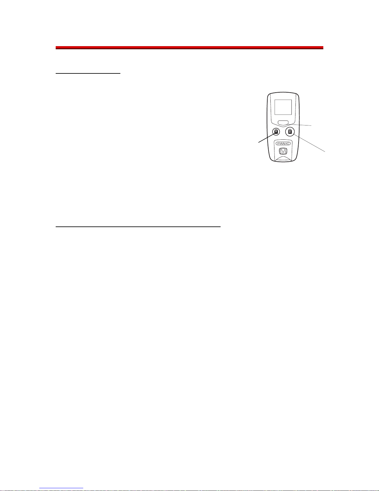
3.0 Remote Controlled Engine Starter Function
Command
Button
Lock/start
button
3.1 Construction
The Remote Control Starter System consists of a transmitter, antenna, control unit, wire harness
and related relays to control large amounts of current without having the large current flow inside
the control unit and wire harness.
3.2 Communication
After receiving the “Starter Signal” from the transmitter, the control unit checks if the
necessary requirements are met to turn on the starter motor by checking the vehicle’s BCAN
line and the switched inputs to the remote starter control unit.
3.3 Conditions Required to Remote Start the Engine
The following conditions must be met to switch on the IG1 relay and the starter motor relay
which start the vehicle.
• All doors are closed. (Door switches: Off)
• Tailgate is closed. (Tailgate switch: Off)
• Engine hood is closed. (Engine hood switch: Off)
• Door locks are activated (Door lock knob unlock switch: Off)
• Transmission select lever is in the P position. (P position switch: On)
• Key is not inserted into the ignition: (Key switch: Off)
• IGN 1 signal is not at 12V.
• Brake pedal is not pressed. (Brake light switch: Off)
• Security alarm signal is not ON.
• System is not in PANIC condition.
6
Honda Remote Control Starter System Service Manual: 2007 CR-V
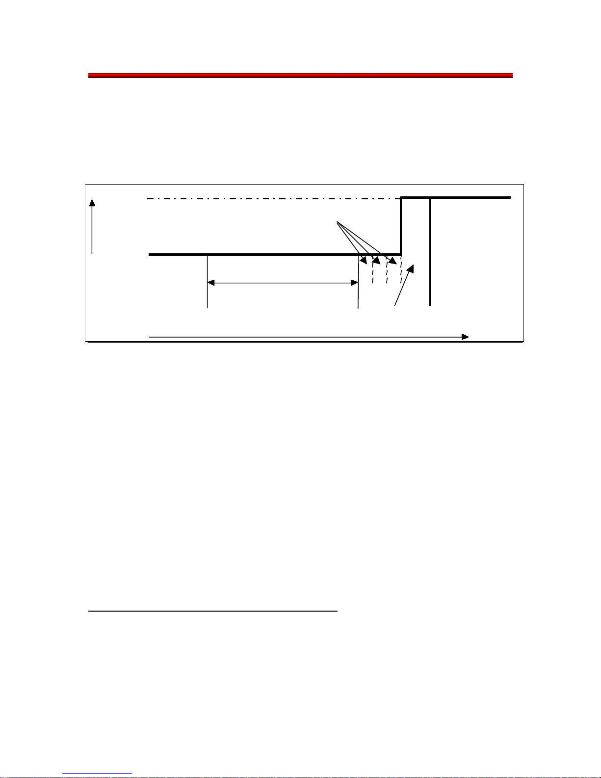
3.4 Determining If the Engine is Running.
The control unit confirms that the engine is running by monitoring the signal from the charge
lamp circuit. The starter motor has a minimum rotating time. After the minimum period has
expired, it will extend the starter in timed steps until the Indication OFF signal from the charge
lamp circuit is received. Once the signal is received, the starter motor has a short delay to
ensure the engine is running and then it stops cranking. As a result the engine continues to
crank for a very brief period as the engine starts to run.
SIGNAL FROM
HARGE LAMP
C
RCUIT
CI
CHARGE LAMP: OFF
STEP EXTENSION OF CRANK TIME
MINUMUM RO TA TING TIME
PROGR A MMED EXTENSION
STARTER MOTOR
STOPPED
TIME
3.5 Conditions Which Will Cause the Engine to Stop
While the engine is running, the control unit stops the engine when 1 of the following signals is
received.
• Door is opened. (Door switch: On)
• Tailgate is opened. (Tailgate switch: On)
• Engine hood is opened. (Engine hood switch: On)
• Transmission select lever is moved from the P position. (P position switch: Off)
• Key is inserted into the ignition switch. (Key switch: On)
• Door locks are released. (Door lock knob unlock switch: On)
• Engine speed exceeds 4000 rpm.
• Engine Malfunction Indicator Lamp turns on.
• Engine low oil pressure indicator comes on.
• The security alarm signal is received.
• The Panic (Active Alarm) signal is received.
• The Panic (Active Alarm) signal is received from the transmitter of the Remote control
Starter System.
• The stop signal from the transmitter of the remote control starter system is received.
• Specified engine running time is completed.
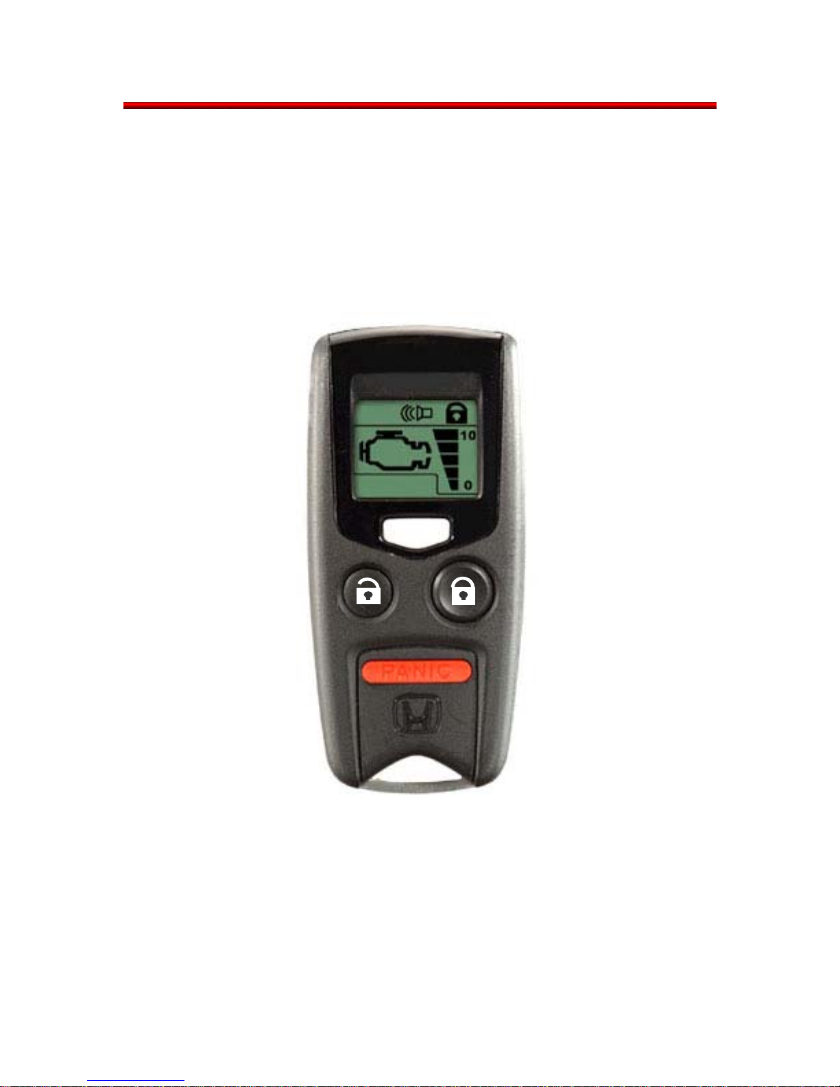
4.0 Remote Starter Answer Back Description
The remote starter has 2-way communication. That means the transmitter can send signals to
the vehicle to start and the vehicle can send signals back to the transmitter to inform the user if
the start was successful. Other information such as the remaining idle time, the door lock status
and the security system status can also be displayed.
7
Honda Remote Control Starter System Service Manual: 2007 CR-V
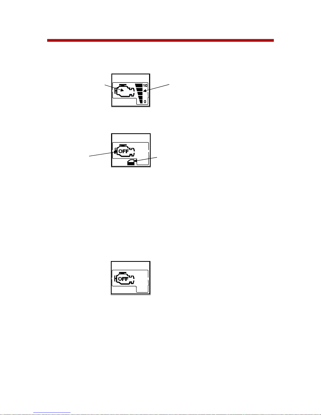
4.1 Answer Back When Starting the Vehicle
When a start is requested, the transmitter will answer back with one of the following:
Engine Run Indicator and remaining idle time
Engine run indicator
This display indicates the remote start was successful and the engine is running
The engine off indicator and the check reminder
Engine off
indicator
The combination of these symbols means the remote start was not allowed when one of the
following conditions is not met.
• All doors are closed. (Door switches: Off)
• Tailgate is closed. (Tailgate switch: Off)
• Engine hood is closed. (Engine hood switch: Off)
• Door locks are activated (Door lock knob unlock switch: Off)
• Transmission select lever is in the P position. (P position switch: On)
• Key is not inserted into the ignition: (Key switch: Off)
• Brake pedal is not pressed. (Brake light switch: Off)
The engine off indicator only.
This symbol has two meanings:
a) the engine start was not successful.
b) the engine stop was successfully completed.
If you get this symbol when trying to start the engine it is likely that the engine has been restarted
more than 2 times without a 20-minute waiting period. See section 5.3
If you get this symbol when trying to stop the engine, the stop was successful and the system is
working normally.
Engine idling time
Check Reminder
8

Honda Remote Control Starter System Service Manual: 2007 CR-V
No answer back.
This screen will be displayed when a start is requested and the transmitter receives no answer
back from the vehicle. It commonly occurs when the transmitter is out of range of the vehicle. If
this symbol appears when trying to start the car at short range without interference, it may
indicate a problem with the remote starter system See section 9.0 for diagnosis.
NOTE: The range of the remote transmitter exceeds the range of the answer back signal. In
some cases the engine will be started but no answer back will be received.
9
Honda Remote Control Starter System Service Manual: 2007 CR-V
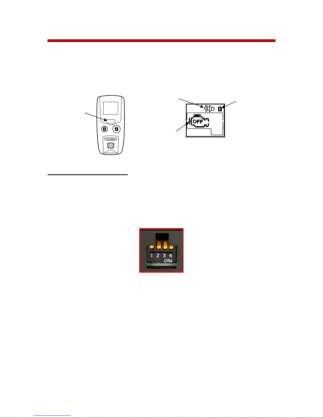
4.2 Answer Back to Check Vehicle Status.
Pressing the command button twice will check the vehicle status.
It will tell you the engine running condition and remaining idling time, the door lock condition and if
the security system has been triggered.
Press
command 2x
5.0 Control Unit Operation.
The control unit sends the engine starter signal to prevent the security system from setting the
alarm. The engine starter signal is also used to stop some functions (power
window/sunroof/wipers) when starting the engine
Security alarm
triggered
Engine Off
Doors locked
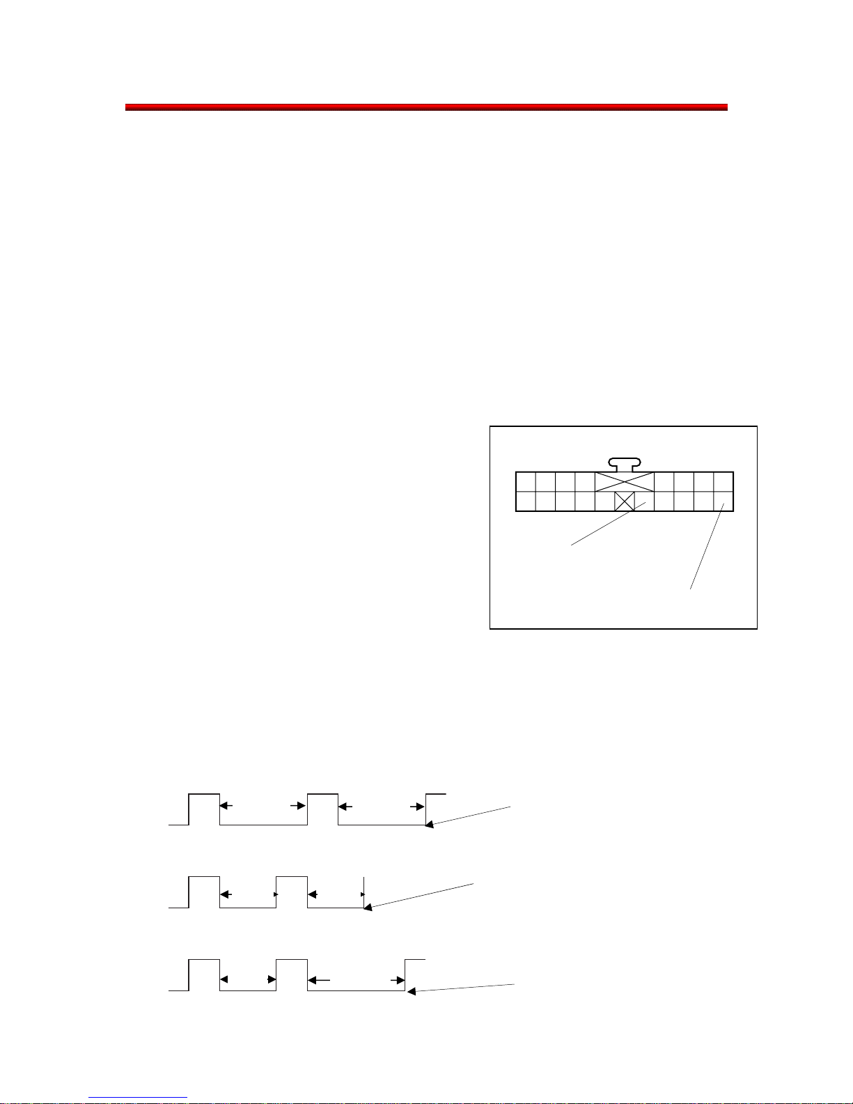
5.1 Function Select Switches
There are 4 switches on the side of the control unit that will allow the control unit to be used with
future Honda models. Refer to the installation instructions to determine how the control unit is
supposed to be pre set.
Switch 1: This switch should be turned on if the car is equipped with a rear junction Unit
For CR-V it remains in the OFF position.
Switch 2: This switch should be turned on if the car is equipped with a lockable tailgate
For CR-V the switch should be in the ON position.
Switch 3: For Japanese market vehicles only.
For CR-V this switch should be in the OFF position
Switch 4: For Japanese market vehicles only.
For CR-V this switch should be in the OFF position
NOTE: After changing the function select switches, the control unit must be powered off
(disconnected) and then powered back on (reconnected) before the changes are registered
10

N
Honda Remote Control Starter System Service Manual: 2007 CR-V
5.2 The Control Unit Buzzer Indicating Cause of “no start”
The control unit can indicate the cause of no start by sounding a buzzer inside the case. This
sound can be heard inside the vehicle after a remote start has been denied because one of the
required starting conditions was not met (Section 3.3). If it is confirmed all conditions to start
have been met and the buzzers still sounds it may indicate a problem with the sensor which
inputs that signal. Refer to the vehicle’s service manual for repair. On a vehicle not originally
equipped with a security system, if the system is indicating a no start due to the hood being open
when the hood is hood closed, refer to section 5.2.1 for further diagnosis.
Engine hood is opened
Transmission select lever is not in Park
or
Brake light switch signal is being sent to
the control unit.
Door is opened
Doors are unlocked
Tailgate is opened
Tailgate is opened
Voltage in charge lamp circuit has
not reached the specified value
Immobilizer code of the remote control starter
system is not matched with the vehicle.
After starting, the Ignition on signal is not sent
to the control unit.
The key is inserted into the ignition switch
Vehicles IG1 signal is sent to the control unit
Engine speed is over 4000 rpm
Engine Malfunction Indicator Lamp is on
Engine Oil Pressure Lamp is on
B-CAN signal is OFF
The most recent cause of no start can also be viewed using the HDS as well.
• Connect the tablet tester to vehicle’s Data Link Connector.
• Turn on the HDS, input the required items, select “HONDA SYSTEMS”, select “R/C
ENGINE STARTER”
• Select “HISTORY”, “ENGINE (DOESN’T) RUN HISTORY”
Sound
o Sound
Pause
Short sound: 200 milliseconds
No sound 00 milliseconds
Long sound: 500 milliseconds
No sound 500 milliseconds
11
(
)
Honda Remote Control Starter System Service Manual: 2007 CR-V
5.2.1 Hood Switch Test. (For vehicles without a factory installed security system)
1. Disconnect the hood switch and inspect for proper operation.
On the hood switch side of connector, with the hood open, is there continuity across
the terminals?
YES – Continue to Step 2
NO – Replace hood switch and retest.
2. Using the shaft of a screw driver press down on the hood latch until it latches in the
closed position.
On the hood switch side of the connector, with the hood switch in the closed position,
is there continuity across the terminals?
YES – Replace the hood switch and retest
NO – Reconnect the hood switch, release
the hood latch by pulling the hood release
lever and continue to step 3.
3. With the hood open and all connectors
connected, is there continuity between pin
14 and 18 of the R/C starter control unit
connector
14 (BLACK): GROUND
YES – Hood switch and wiring is OK replace
R/C starter control unit.
NO – Repair open or short in hood switch
18 (WHITE/RED): HOOD SWITCH
As viewed from wire side
wiring.
5.3 Restarting with the Remote Transmitter
To prevent excessive carbon monoxide accumulation in and around the vehicle, the maximum
engine running time is 10 minutes. The number of times the engine can be restarted with the
remote control is also limited. The engine can only be started three times without a 20 minute
waiting period between the time the engine was stopped and the time it is restarted with the
remote.
RUN
WAIT
RUN
WAIT
RUN
WAIT
12
More than
20 Min.
Less
than
20 Min.
Less
than
20 Min.
Less
than
20 Min.
More than
20 Min.
More than
20 Min.
Re-running: Allowed.
Re-running: Not allowed. (Engine-Off Indicator
on transmitter is turned on.)
Re-running: Allowed.

Honda Remote Control Starter System Service Manual: 2007 CR-V
For diagnostic and sales demonstration purposes a running time less tha n 30 seconds is not
counted as a start. An unlimited number of restarts can be performed provided the engine is run
less than 30 seconds.
6.0 Keyless Entry Function
6.1 Locking
The control unit activates the door locks if the “locking signal” from the transmitter is received and
the following conditions are met.
• All doors are closed. (Door switches: Off)
• Tailgate is closed. (Tailgate switch: Off)
• Key is not inserted into the ignition switch. (Key switch: Off)
• IG1 line is not at 12V
To inform you that the doors have been locked, the parking lights blink once and the door lock
Indicator shows up on the transmitter. If the lock/start button is pressed again within 5 seconds of
the first push, the control unit sounds the horn once to confirm that the door locks are already
activated.
6.2 Unlocking
The control unit releases the driver’s door lock, when the “Unlocking Signal” from the transmitter
is received. The parking lights blink twice and the “door unlock indicator” shows up on the
transmitter indicating the driver’s door lock is released. If the Unlock/Stop button is pressed again
within 30 seconds all door and tailgate locks will release.
6.3 Relocking
If the door is not opened, the control unit re-activates the door locks automatically 30 seconds
after the last Unlock/Stop button is pressed. The parking lights do not blink when re-locking.
The re-locking is stopped when any 1 of the following conditions is met.
• Door is opened. (Door switch: On)
• Tailgate is opened. (Tailgate switch: On)
• Key is inserted into the ignition switch. (Key switch: On)
• IG1 signal is sent.
6.4 Panic (Active Alarm)
When the PANIC button is pressed and held for more than 1 second, the control unit sounds the
alarm for 30 seconds.
When the alarm is sounding, the headlights, parking lights, and horn are turned on intermittently
The control unit stops the alarm when any of the following signals are received.
The PANC (active alarm) signal
The Engine start signal from the remote transmitter
The Engine stop signal from the remote transmitter
The Lock signal from the keyless entry
The Unlock signal from the keyless entry
The Tailgate open signal from the transmitter
13
Honda Remote Control Starter System Service Manual: 2007 CR-V
6.5 Security Alarm and Panic Alarm
• If the security system sets off the alarm, it can only be turned off using the unlock/stop
button and not the PANIC button.
• If the PANIC button is used to activate the alarm, any button will turn off the alarm.
• If the PANIC button is used to activate the alarm, and while sounding, the security system
also activates the alarm, the security system takes precedence and only the Unlock/Stop
button will deactivate the alarm
Unlock/Stop
PANIC
Lock/Start
14
A
Honda Remote Control Starter System Service Manual: 2007 CR-V
7.0 System Descriptions
7.1 Body Controller Area Network (B-CAN)
The engine control unit is connected to the body controller area network (B-CAN) This network
enables the engine starter control unit to communicate with the gauge control module, the
Multiplex Integrated Control Unit (MICU) and the immobilizer control unit.
PGM-FI ECU
GAUGE CONTROL
SRS
BS/VSA
TPMS
YAW/G SENSOR
B-CAN
FCAN
CLIMATE CONTROL
IMMOBILIZER/KEYLESS
OPTIONAL REMOTE
STARTER
MICU
15
Honda Remote Control Starter System Service Manual: 2007 CR-V
7.2 Diagnostic Trouble codes for the B-CAN systems
There are 3 types of diagnostics available for the B-CAN communication system
• Internal Error DTCs
• Loss of Communication DTCs
• Signal Error DTCs
Internal Error DTCs The ECUs run internal checks. If one finds that
there is an internal ECU problem, it will set an
internal error DTC. This indicates that the ECU
needs to be replaced.
Loss of Communications DTCs Loss of communication DTCs (and BUS-off
DTCs) are set when there is a problem with the
communication between ECUs. This could be
in the connections, the wiring or the ECU.
Signal Error DTCs The ECUs can run diagnostics on some input
circuits to determine if that circuit is functioning
properly (no open or short circuits). If a circuit
fails the diagnostic test, a DTC will set (NOTE:
Not all input circuits are tested for errors.)
16
Honda Remote Control Starter System Service Manual: 2007 CR-V
7.2.1 Loss of Communication Cross-Reference Chart
Receiving Unit/Loss of Communication DTC
Transmitting
Control Unit
Multiplex
Integrated
Control Unit
(MICU)
Gauge
Control
Module
SRS SRS B1187
VSA VSA B1170
TPMS TPMS B1173
Message
RM B1188 B2259
HLSW B1155
WIPSW B1156
MICU B1157 B2256
DOORSW B1159 B2255
DRLOCKSW B1160 B1905 B2262
VSP/NE B1011 B2258
A/T B1008 B1906 B2257
CDS(SRS) B1032
ILLUMI B2263
ENG B1168 ECM/PCM
A/T B1169
Multiplex
Integrated
Control Unit
(MICU)
Gauge
Control
Module
Immobilizer
Keyless Entry
Control Unit
Engine
Starter
Control Unit
7.2.2 B-CAN System Switch Device Index for Remote Control Engine Starter
Control Unit Function Input
Multiplex
Integrated
Control Unit
(MICU)
Gauge Control
Module
Daytime Running Lights Transmission Switch (P position)
Power Door Locks (Vehicle Speed Sensor) Vehicle Speed Pulse
Engine RPM
Door Lock Response Operation Door Lock Signal
Keyless Entry System Keyless Lock Signal
Keyless PANIC Keyless PANIC Signal
Security Alarm Signal Keyless Lock Signal
Door Lock Signal
Communication with MICU Vehicle Speed Pulse
Engine RPM
17
Honda Remote Control Starter System Service Manual: 2007 CR-V
7.2.3 Troubleshooting B-CAN system DTCs
Signal Error DTCs
B2250: Short-circuit in CAN line to ground or open circuit
If B2250 is shown whenever the HDS is used, the remote controlled engine starter will not work
consistently. Repair the CAN LINE first, then check other DTC’s
NOTE: To determine if there is an intermittant or permanent wiring failure, clear the DTCs before
troubleshooting with the tablet tester. Intermittant failures may require additional diagnostic
work.
NOTE: If the engine can be started with the remote and is stopped within a few seconds, make
sure that the vehicle Malfunction Indicator Lamp or the oil pressure warning lamp are not causing
the control unit to shut down the engine.
18
Honda Remote Control Starter System Service Manual: 2007 CR-V
8.0 Remote Starter Problem Diagnosis
The following cross-reference chart lists some symptoms and possible component failures that
could cause these symptoms.
If the problem is discovered immediately following installation, please refer to Section 27 for a
quick reference chart of disconnected parts to results.
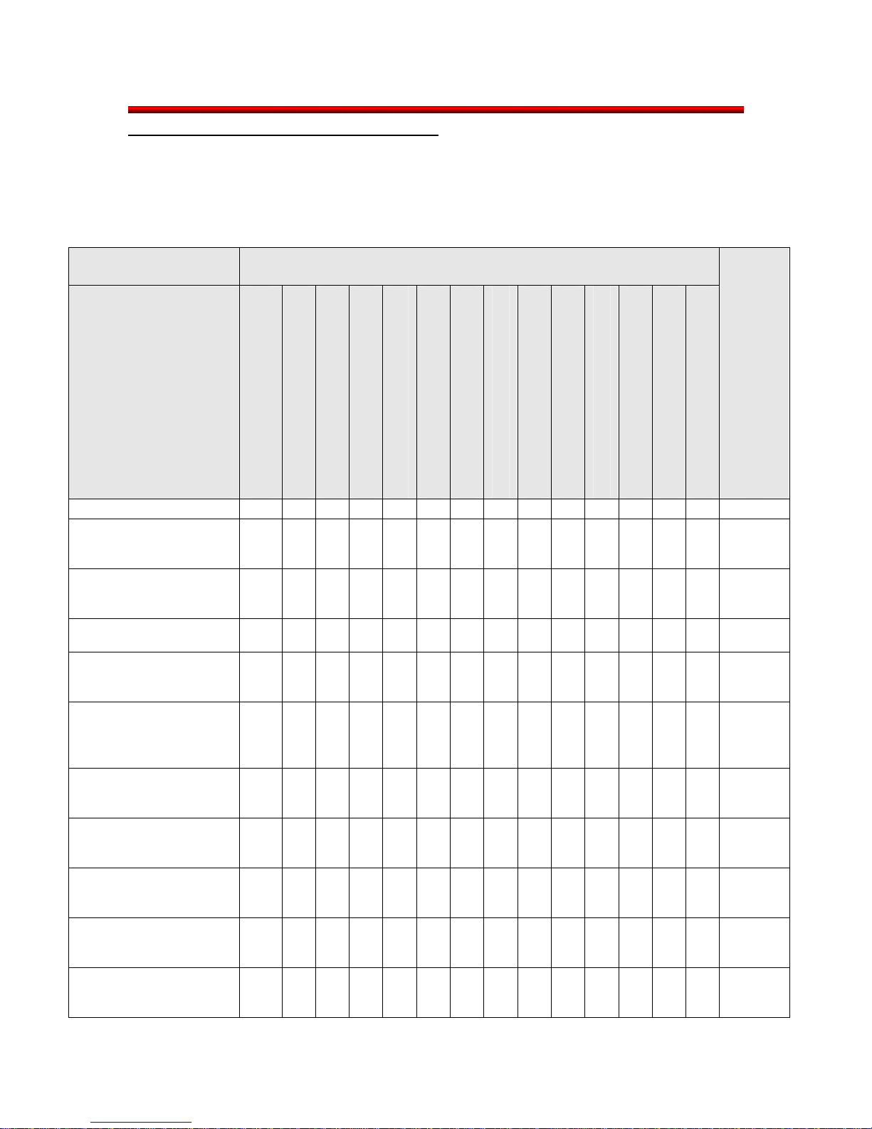
8.1 Symptom and Possible Cause Chart
Item to be checked
Transmitter
Control Unit
3A Fuse (Orange-Red)
3A FUSE (Yellow-Gray)
Symptom
Engine does not rotate.
Engine can start to
rotate, but does not
continue to run.
Starter motor does not
turn off when engine
is running.
Engine will not stop
using transmitter.
Heater/air conditioner
does not operate
when running.
With front wiper switch
turned on, the front
wipers continue to
operate during running.
Engine does not stop
when door is
opened.
Engine does not stop
when tailgate is
opened.
Engine does not stop
when key is inserted
into ignition.
Engine does not stop
when brake pedal is
pressed.
Engine does not stop
when shifter is out of
Park.
× × × × × × × ×
×
× ×
×
×
×
×
×
×
×
×
40A Fuse (White-Light Green)
IG1 Relay
30A Fuse (White-Pink)
IG2 Relay
Solenoid Cut Relay
Starting Motor Relay
Engine Hood Switch
×
×
Refer to page
Wire Harness
Sunroof Cut Relay
Power Window Cut Relay
×
×
×
19
Honda Remote Control Starter System Service Manual: 2007 CR-V
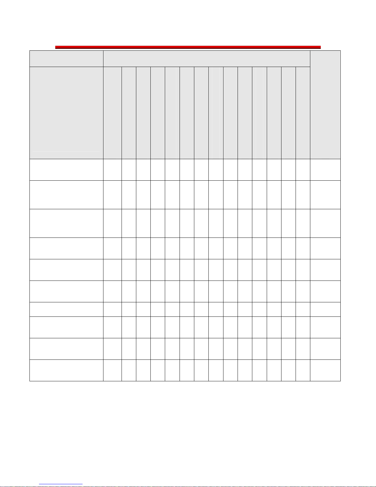
Item to be checked
Symptom
Engine does not stop
when engine speed
exceeds 4000 rpm.
Engine does not stop
when hood is open.
(Security System
Equipped Model)
Engine does not stop
when hood is open.
(Security System Not
Equipped Model)
Engine does not stop
when driver's door
lock is released.
Engine does not stop
when oil pressure
light is on.
Engine does not stop
when MIL is turned
on.
Engine does not stop
with PANIC Signal.
Shift lock solenoid
operates after vehicle is
started with remote.
Power window operates
after vehicle is started
with remote.
Sunroof operates after
vehicle is started with
remote.
Transmitter
Control Unit
×
×
×
×
×
×
× ×
IG1 Relay
3A Fuse (Orange-Red)
3A FUSE (Yellow-Gray)
30A Fuse (White-Pink)
40A Fuse (White-Light Green)
Starting Motor Relay
IG2 Relay
Solenoid Cut Relay
Engine Hood Switch
Sunroof Cut Relay
Power Window Cut Relay
×
×
×
× ×
Refer to page
Wire Harness
×
×
20
 Loading...