

Honda CH250 (1989), ELITE 250 (1989) Service Manual
I Index
Charging System/Alternator
1-"
I~
Introduction
This
service
manual
describes
the
service
procedures
for
and
technical
featuresofthe
CH250.
This
Model
Specific
Manual
includes
every
service
pro-
cedure
thatisofaspecific
nature
to
this
particular
model.
Basic
service
procedures
that
are
common
to
other
Honda
Motorcycle/Motor
Scooter/ATVs
are
cov-
eredinthe
Common
Service
Manual.
This
Model
Spe-
cific
Service
Manual
shouldbeused
together
with
the
Common
Service
Manualinordertoprovide
complete
service
information
on
all
aspectsofthis
motorcycle.
Follow
the
Maintenance
Schedule
(Section
3)
recom-
mendationstoensure
that
the
vehicleisin
peak
operat-
ing
condition
and
the
emission
levels
are
within
the
standards
set
by
the
U.S.
Environmental
Protection
Agency
and
the
California
Air
Resources
Board.
Performing
the
first
scheduled
maintenanceisvery
im-
portant.Itcompensates
for
the
initial
wear
that
occurs
during
the
break-in
period.
Section1and3applytothe
whole
motorcycle,
Section
2
illustrates
procedures
for
removal/installation
of
com-
ponents
that
may
be
requiredtoperform
service
de-
scribedinthe
following
sections.
While
Section4through18describe
partsofthe
motor-
cycle,
grouped
accordingtolocations.
Find
the
section
you
wantonthis
page,
then
turntothe
tableofcontentsonthe
first
pageofthe
section.
Most
sections
describe
the
service
procedure
through
a
system
illustration.
Refertothe
next
page
for
details
on
holl}'touse
this
manual.
If
you
don't
know
the
sourceofthe
trouble,goto
Sec-
tion19TROUBLESHOOTING.
ALL
INFORMATION,
ILLUSTRATIONS, DIREC-
TIONS
AND
SPECIFICATIONS INCLUDED
IN
THIS PUBLICATION ARE BASED ON THE LATEST
PRODUCT
INFORMATION
AVAILABLE
AT
THE
TIME
OF
APPROVAL FOR PRINTING.
HONDA
MOTOR CO., LTD. RESERVES THE RIGHT
TO
MAKE CHANGES
AT
ANY
TIME
WITHOUT
NOTICE AND
WITHOUT
INCURRING
ANY
OBLI-
GATION
WHATEVER.
NO PART OF
THIS
PUBLI-
CATION
MAY
BE
REPRODUCED
WITHOUT
WRITTEN PERMISSION.
THIS
MANUALISWRIT-
TEN
FOR
PERSONS
WHO
HAVE
ACQUIRED
BASIC KNOWLEDGE OF
MAINTENANCE
ON
~~~~~~_~OTORCYCLES,
MOTOR
SCOOTERS
.I
HONDA
MOTOR
CO., LTD.
SERVICE PUBLICATION OFFICE
DateofISSue:
May,
1989
©
HONDA
MOTOR
CO.,
LTD.
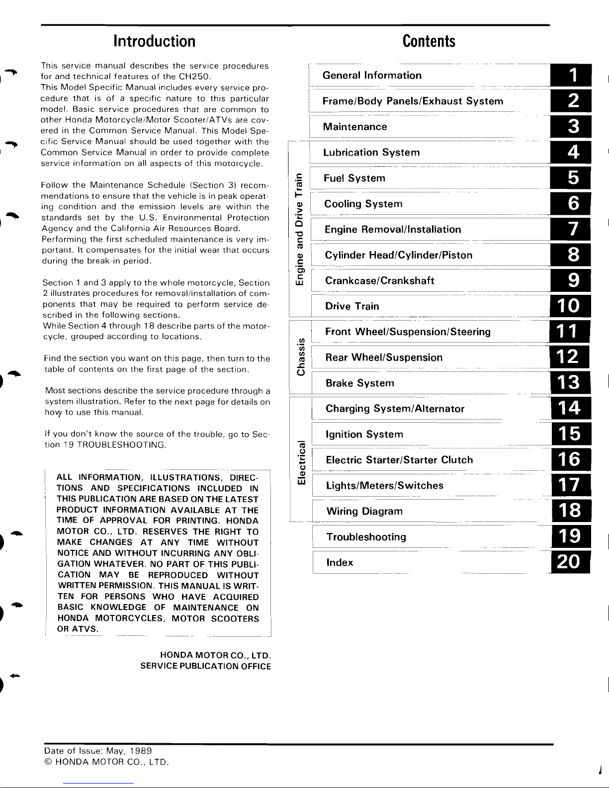
Contents
l.
General
Informa-tio-n---
-
--
_~_-
..
~ame/BOdY
Panels/Exhaust
System--
---1fJI
~intenanc~
-iii
I.§
Ii
~::;i:::~:mSYstem
-
-=
I-
r---
~
~
LCooling
System_..-:.I'
'':::
~
[Engine
Removal/Installation
==-
~
LCYlinder Head/Cylinder/Piston -----=__
UJ
~I
~
I
L
Crankcase/Crankshaft
..
~e
Trai~
__
.
~~~_-_~-~=-
!
IJJ
In
Front
Whe-e-I/-S-usp~nsion/Steering
__
~
! 5
l
~
=:=:=:=~=eW=s=:=:=::-::-~~-~S--p-.
e_ns_io_n
.
---~-It
-~_DI
-=all
~_-m
III
lEI
___
..
-m
-
--m
How
to
Use
This
Manual
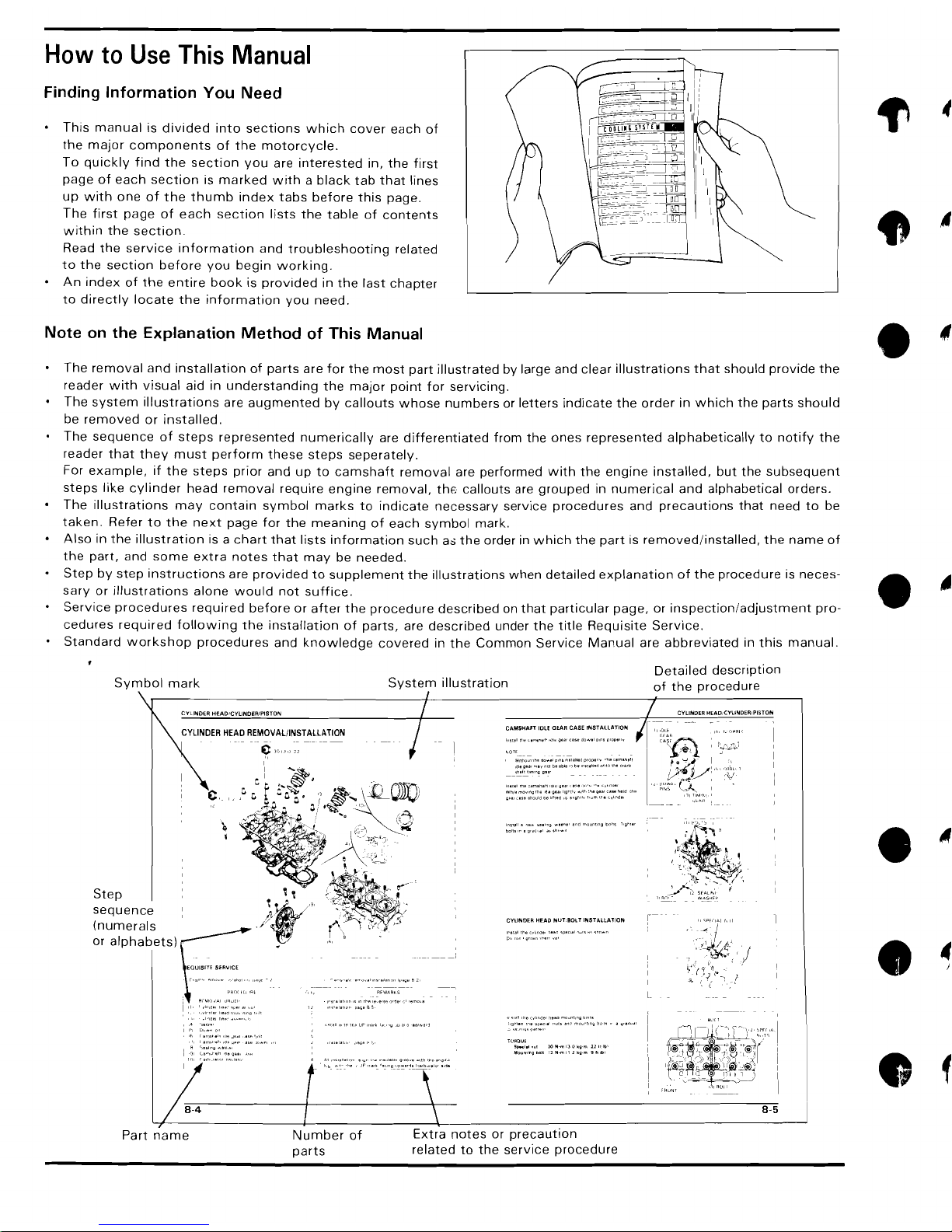
Finding Information You Need
This
manual
is
divided
into
sections
which
cover
each
of
the
major
components
of
the
motorcycle.
To
quickly
find
the
section
you
are
interested
in,
the
first
page
of
each
section
is
marked
with a black
tab
that
lines
up
with
one
of
the
thumb
index
tabs
before
this
page.
The
first
page
of
each
section
lists
the
table
of
contents
within
the
section
Read
the
service
information
and
troubleshooting
related
to
the
section
before
you
begin
working.
An
index
of
the
entire
book
is
provided
in
the
last
chapter
to
directly
locate
the
information
you
need.
Note
on
the Explanation
Method
of This Manual
The
removal
and
installation
of
parts
are
for
the
most
part
illustrated
by large and
clear
illustrations
that
should
provide
the
reader
with
visual
aid in
understanding
the
major
point
for
servicing.
The
system
illustrations
are
augmented
by
callouts
whose
numbers
or
letters
indicate
the
order
in
which
the
parts
should
be
removed
or
installed.
The
sequence
of
steps
represented
numerically
are
differentiated
from
the
ones
represented
alphabetically
to
notify
the
reader
that
they
must
perform
these
steps
seperately.
For
example,
if
the
steps
prior
and
up
to
camshaft
removal
are
performed
with
the
engine
installed,
but
the
subsequent
steps
like
cylinder
head
removal
require
engine
removal,
the
callouts
are
grouped
in
numerical
and
alphabetical
orders.
The
illustrations
may
contain
symbol
marks
to
indicate
necessary
service
procedures
and
precautions
that
need
to
be
taken.
Refer
to
the
next
page
for
the
meaning
of
each
symbol
mark.
Also
in
the
illustration
is a
chart
that
lists
information
such
as
the
order in
which
the
part
is
removed/installed,
the
name
of
the
part,
and
some
extra
notes
that
may
be
needed.
Step
by
step
instructions
are
provided
to
supplement
the
illustrations
when
detailed
explanation
of
the
procedure
is
neces-
sary
or
illustrations
alone
would
not
suffice.
Service
procedures
required
before
or
after
the
procedure
described
on
that
particular
page,
or
inspection/adjustment
pro-
cedures
required
following
the
installation
of
parts,
are
described
under
the
title
Requisite
Service.
Standard
workshop
procedures
and
knowledge
covered
in
the
Common
Service
Manual
are
abbreviated
in
this
manual.
Detailed
description
Symbol
mark
System
illustration
of
the
procedure
CAMSHAFT
IDLE ClEAR CASE rNSTALLATlOJilj
- I
In"." , 00"
".',og
",una'
sod
moun"ng
boilS
"~hr.'
boll"e,g"'J".,.,.h,,,,
..
,,
Step
sequence
CYLINDER
HEAD
REMOVAL/INST
ALLATION
CVLINDER HEAD/CYUNDER/PiSTON
CYUNDER HEAD
NUT:80l
T INSTALLATION
(numerals
or
alphabets)
H)~aUE
~~I.'""'
lO'-l"m
IJOkg-m
II
"·1.'
J,loum1ng
Mlt
12
~·m
II"kg-m
9 h
Ib'
8-5
•
•
•
•
•
Part
name
Number
of
Extra
notes
or
precaution
parts
related
to
the
service
procedure
I
--
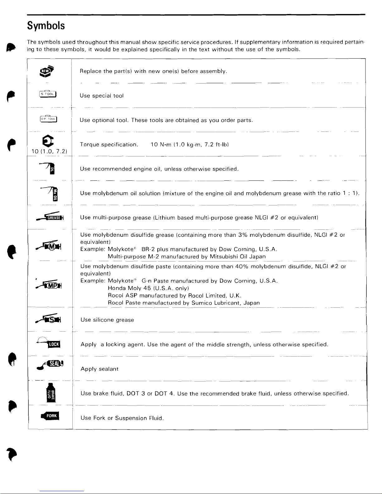
Symbols
Tre
symbols
used
throughout
this
manual
show
specific
service
procedures.
If
supplementary
information
is
required
pertain-
ing
to
these
symbols,
it
would
be
explained
specifically
in
the
text
without
the
use
of
the
symbols.
I
~~
lIlIIiiijlll
[5"
TOOL)
~
0
10
(1.0,7.2)
~
II
-~
.....
f
Replace
the
part(s)
with
new
one(s)
before
assembly.
Use
special
tool
Use
optional
tool.
These
tools
are
obtained
as
you
order
parts.
Torque
specification.
10
N·m
(1.0
kg-m,
7.2
ft-Ib)
Use
recommended
engine
oil,
unless
otherwise
specified.
Use
molybdenum
oil
solution
(mixture
of
the
engine
oil and
molybdenum
grease
with
the
ratio
: 1).
Use
multi-purpose
grease
(Lithium
based
multi-purpose
grease
NLGI
#2
or
equivalent)
Use
molybdenum
disulfide
grease
(containing
more
than
3%
molybdenum
disulfide,
NLGI
#2
or
equivalent)
Example:
Molykote'
BR-2
plus
manufactured
by
Dow
Corning,
U.S.A.
Multi-purpose
M-2
manufactured
by
Mitsubishi
Oil
Japan
---
..
_-
---
-----
---.
--------
Use
molybdenum
disulfide
paste
(containing
more
than
40%
molybdenum
disulfide,
NLGI
#2
or
equivalent)
I
Example:
Molykote'"'
G-n
Paste
manufactured
by
Dow
Corning,
U.S.A.
Honda
Moly
45
(U.S.A.
only)
Rocol
ASP
manufactured
by
Rocol
Limited,
U.K.
I
Rocol
Paste
manufactured
by
Sumico
Lubricant,
Japan
_._--------
~,--r
~
I Use
silicone
grease
IApply
"acking
,gent.
U"
tho
'·9::'
tho
middle
""o9th,
001",
athmW":::C~"od
~I~
1
..
I
Apply
sealant
I
1-
U"
b"ko
f1oid,
D~T
3
a,
DO~U"
tho
"cammondod
b"ko
f1oid,
oolm
athmwl"
,peclfi,d
--,---
[
U"
Fmk m S",pon"ao
Floid.
I
1.
General
Information
General
Safety
1-1
Model
Identification
1-2
Specifications
1-3
Torque
Values
1-10
Tools
1-12
General
Safety
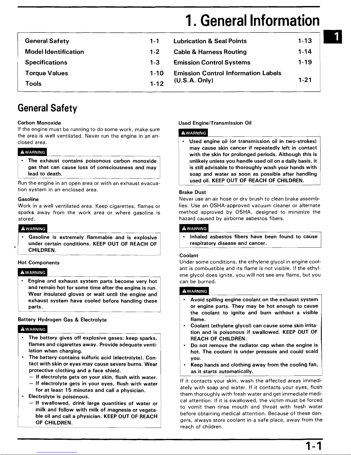
Carbon
Monoxide
If
the
engine
must
be
running
to
do
some
work,
make
sure
the area is
well
ventilated.
Never
run
the
engine in an en-
closed area.
~s
poisonous
carbon
monoxide
gas
that
can
cause
loss
of
consciousness
and
may
~todeath.
Run
the
engine in an
open
area or
with
an
exhaust
evacua-
tion
system
in an
enclosed
area.
Gasoline
Work
in a
well
ventilated
area. Keep
cigarettes,
flames
or
sparks
away
from
the
work
area
or
where
gasoline is
stored.
Gasoline is
extremely
flammable
and is
explosive
under
certain
conditions.
KEEP
OUT
OF REACH OF
, I CHILDREN.
Hot
Components
Engine and
exhaust
system
parts
become
very
hot
I
and
remain
hot
for
some
time
after
the
engine
is run.
Wear
insulated
gloves
or
wait
until
the
engine
and
exhaust
system
have
cooled
before
handling
these
Lparts.
Battery
Hydrogen
Gas &
Electrolyte
• The
battery
gives
off
explosive
gases;
keep
sparks,
flames
and
cigarettes
away.
Provide
adequate
venti-
lation
when
charging.
• The
battery
contains
sulfuric
acid
(electrolyte).
Con-
tact
with
skin
or
eyes
may
cause severe
burns.
Wear
protective
clothing
and a
face
shield.
-
If
electrolyte
gets
on
your
skin,
flush
with
water.
-
If
electrolyte
gets
in
your
eyes,
flush
with
water
for
at
least
15
minutes
and
call a
physician.
•
Electrolyte
is
poisonous.
-
If
swallowed,
drink
large
quantities
of
water
or
I
,
milk
and
follow
with
milk
of
magnesia
or
vegeta-
ble
oil
and
call a
physician.
KEEP OUT OF REACH
OF CHILDREN.
Lubrication
& Seal
Points
1-13
III
Cable &
Harness
Routing
Emission
Control
Systems
Emission
Control
Information
Labels
(U.S.A.
Only)
1-14
1-19
1-21
Used
Engine/Transmission
Oil
• Used engine oil (or
transmission
oil in
two-strokesl
may
cause skin
cancer
if
repeatedly
left
in
contact
with
the
skin
for
prolonged
periods.
Although
this
is
unlikely
unless
you
handle
used oil
on a daily
basis,
it
is still advisable
to
thoroughly
wash
your
hands
with
soap and
water
as
soon
as possible
after
handling
used oil.
KEEP
OUT
OF REACH OF CHILDREN.
Brake
Dust
Never use an air hose or
dry
brush
to
clean brake assemb-
lies. Use an
OSHA-approved
vacuum
cleaner or alternate
method
approved
by
OSHA,
designed
to
minimize
the
hazard caused by airborne
asbestos
fibers.
Inhaled
asbestos
fibers
have
been
found
to
cause
"---
respiratory
disease and cancer.
Coolant
Under
some
conditions,
the
ethylene
glycol
in engine cool-
ant
is
combustible
and
its
flame
is
not
visible.
If
the
ethyl-
ene
glycol
does
ignite,
you
will
not
see
any
flame,
but
you
can be burned.
•
Avoid
spilling
engine
coolant
on
the
exhaust
system
or
engine
parts.
They
may
be
hot
enough
to
cause
the
coolant
to
ignite
and
burn
without
a visible
flame.
•
Coolant
(ethylene
glycol)
can
cause
some
skin irrita-
tion
and is
poisonous
if
swallowed.
KEEP
OUT
OF
REACH OF CHILDREN.
•
Do
not
remove
the
radiator
cap
when
the
engine is
hot.
The
coolant
is
under
pressure and could scald
you.
• Keep hands and
clothing
away
from
the
cooling
fan,
as
it
starts
automatically.
'I
If
it
contacts
your
skin,
wash
the
affected
areas
immedi-
ately
with
soap and
water.
If
it
contacts
your
eyes, flush
them
thoroughly
with
fresh
water
and
get
immediate
medi-
cal
attention.
If
it
is
swallowed,
the
victim
must
be
forced
to
vomit
then
rinse
mouth
and
throat
with
fresh
water
before
obtaining
medical
attention.
Because
of
these
dan-
gers,
always
store
coolant
in a
safe
place,
away
from
the
reach
of
children.
1-1
L
General Information
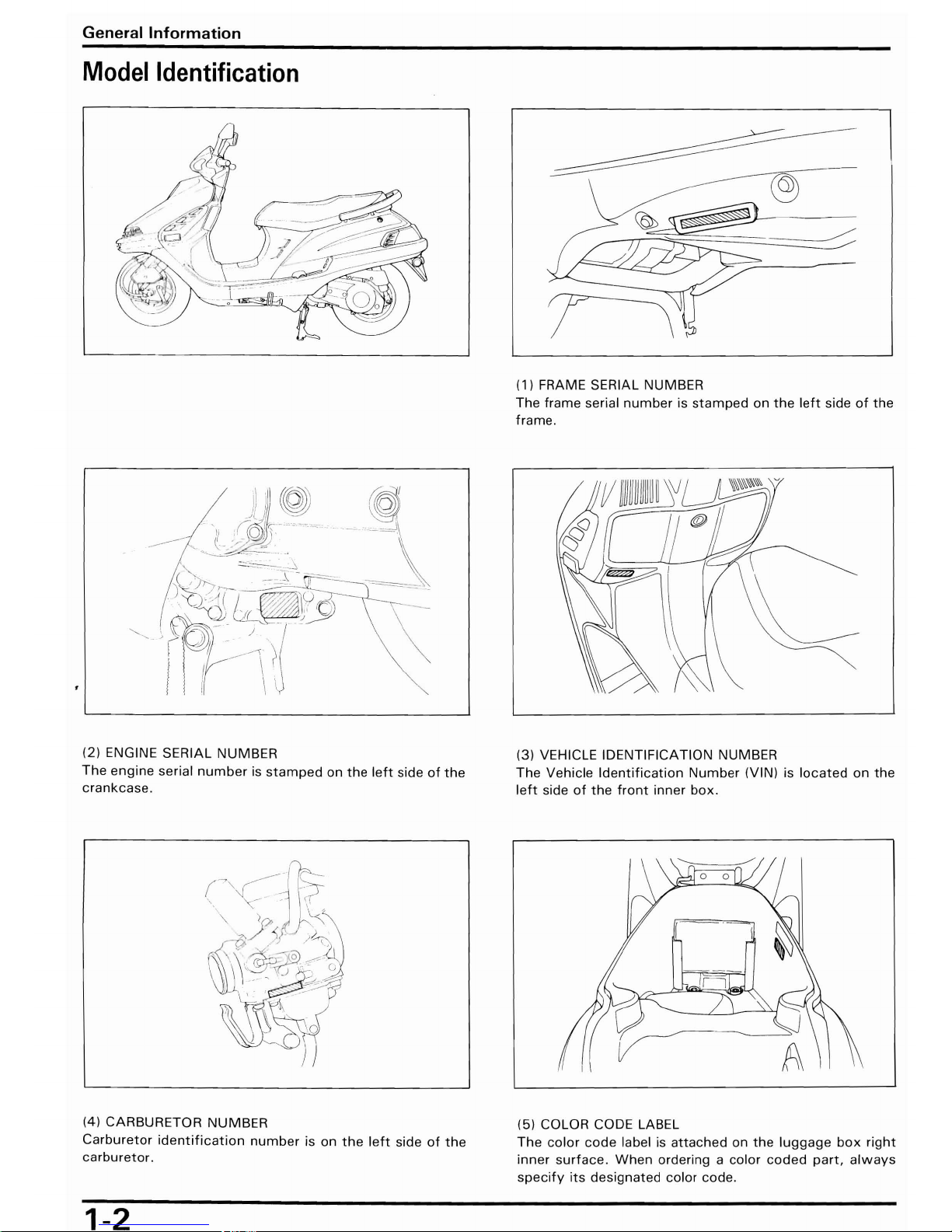
Model
Identification
(1) FRAME SERIAL NUMBER
The frame serial
number
is
stamped
on
the
left
side
of
the
frame .
......
~
.~\
(2) ENGINE SERIAL NUMBER
The
engine
serial
number
is
stamped
on
the
left
side
of
the
crankcase.
(3) VEHICLE IDENTIFICATION NUMBER
The Vehicle
Identification
Number
(VIN) is
located
on
the
left
side
of
the
front
inner
box.
(4) CARBURETOR NUMBER
(5) COLOR CODE LABEL
Carburetor
identification
number
is
on
the
left
side
of
the
The
color
code
label is
attached
on
the
luggage
box
right
carburetor.
inner
surface.
When
ordering a color
coded
part,
always
specify
its
designated color code.
1-2
-----
General
Information
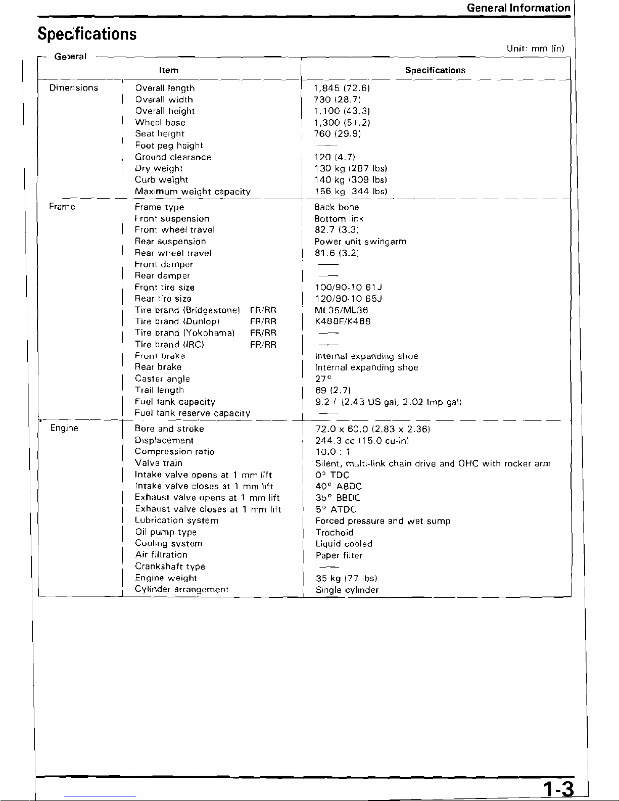
Speo'fications
Unit:
mm
(in)
,....
Geleral
Specifications
_.
;~
It_e_m~~~
~
__
~--
__.__
ornensions
Overall
length
'
1,845
(72.6)
Overall
width
730
(28.7)
Overall
height
1,100
143.31
Wheel
base
1,300151.21
Seat
height
760
129.91
Foot
peg
height
Ground
clearance
12014.71
Dry
weight
I
130
kg
[287
Ibsl
Curb
weight
.
140
kg
1309 Ibsl
Maximum
weight
capacity
~
156
kg
!344
Ibsl
---~-
------
------_._-
----
Frame
Frame
type
Back
bone
Front
suspension
Bottom
link
I
Front
wheel
travel
82.7
13.31
Rear
suspension
Power
unit
swing
arm
I
Rear
wheel
travel
I
81.6
13.21
Front
damper
Rear
damper
I
Front
tire
size
100/90·10
61J
Rear
tire
size
120/90·1065J
I
Tire
brand
(Bridgestonel
FRIRR
ML35/ML36
Tire
brand
(Dunlop)
FR/RR
K488F/K488
I
Tire
brand
IYokohamal
FR/RR
Tire
brand
IIRel
FR/RR
Front
brake
I
Rear
brake
Caster
angle
I
Trail
length
Fuel
tank
capacity
\
Fuel
tank
reserve
capacity
-En-g-ine--
-r
Bore
an-d-st-ro-ke
Displacement
Compression
ratio
Valve
train
Intake
valve
opens
at 1 mm
lift
Intake
varve
closes
at 1 mm
lift
Exhaust
valve
opens
at 1 mm
lift
Exhaust
valve
closes
at 1 mm
lift
Lubrication
system
Oil
pump
type
Cooling
system
Air
filtration
Crankshaft
type
Engine
weight
35
kg
177
Ibs)
Cylinder
arrangement
Single
cylinder
1-3
General
Information
Unit:
111m
(in)
r-
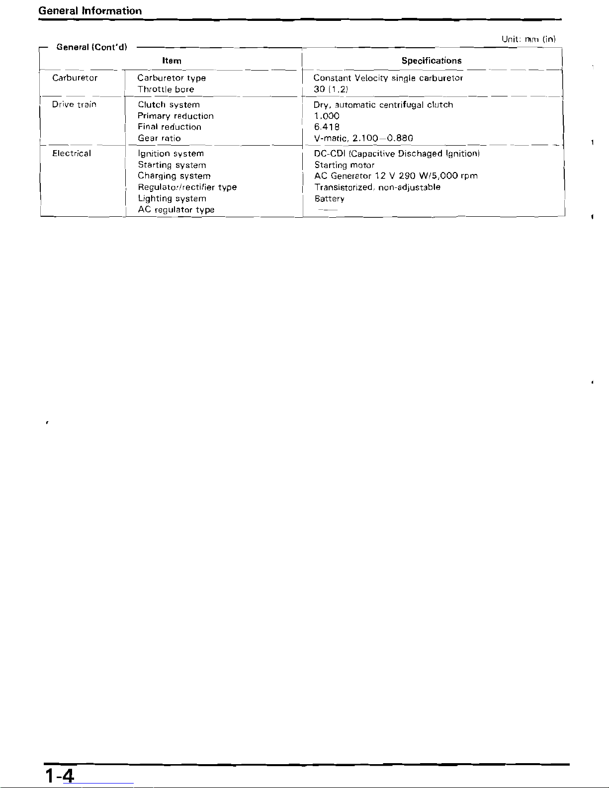
General
(Cant'd)
b
,
Item
I
Specifications
Carburet~-
I
Carburetor
type
--
---
r
Constant
Velocity single
carburetor
--
--
-
---
I
Throttle
bore
21
t-
30
(1
-------1
-Dry,
~tomatlc
centrlfug~
clutch--
-~I:;~al~--
r~tCh
sy';tem
---
--
--
---
l
Primary
reduction
I Final
reduction
_____
----J~r
ratio
Electncal
I
Ignition
system
-
1.000
6
418
---l_v-matlc,
2.100-0.880
I DC-COl (CapacItIve
Dischaged
Ignition)
_
II
Starting
system
Charging
system
i
Starting motor
AC Generator
12 V 290
W/5,OOO
rpm
I
Hegulator/rectifier
type
I
Transistorized,
non-adjustable
I
Lighting
system
I
Battery
I
AC
regulator
type
I
~
1-4
••
General
Information
Unit:
mm
(in)
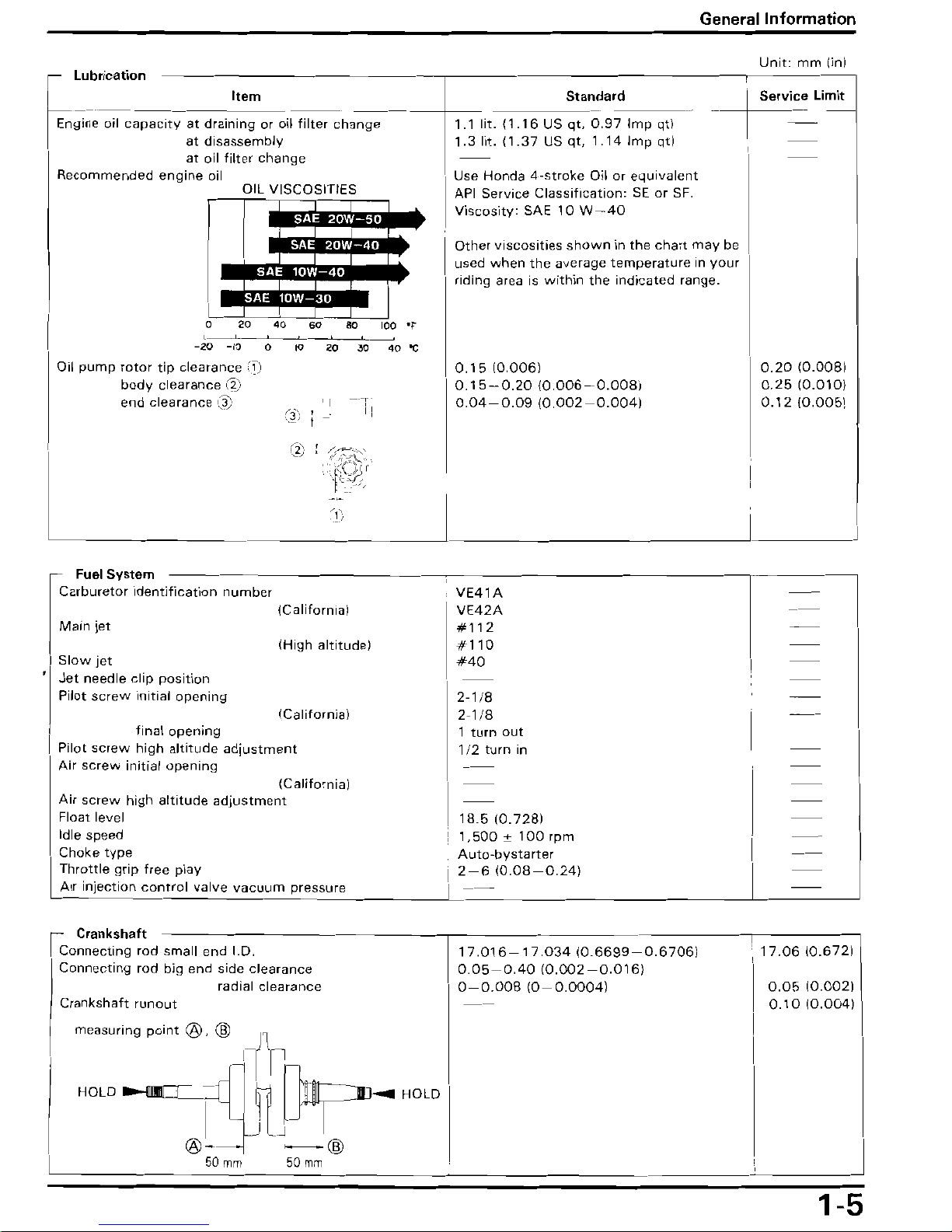
En:::ri:~t~:~acity
at
dra;:::;
or
oil
filter
change
-*
1 lit. 11.16 US
::~:d:r;
Imp qtl
at
disassembly
~:3Iit.
11.37 US qt,
1.141mp
qtlI
at
oil
filter
change
Recommended
engine
oil
Use
Honda
4-stroke
Oil
or
eqlJivalent
OIL
VISCOSITIES
m
API Service
Classification:
SE
or
SF.
Viscosity:
SAE
10
W-40
.,
Other
viscosities
shown
in
the
chart
may
be
used
when
the
average
temperature
in
your
riding
area is
within
the
indicated
range.
o
20
40
60
80
loo-r
-20
-10
0
to
20
30
40"C
Oil
pump
rotor
tip
clearance
0.15
10.0061
body
clearance
\~)
0.15-0.2010.006-0.0081
end
clearance
I't'
,
0.04-0.0910.002--0.0041
I -
I'i
I:
Fuel
System
Carburetor
identification
number
VE41A
(California)
VE42A
Main
jet
#112
(High
altitude)
#110
Slow
jet
#40
Jet
needle
clip
position
Pilot
screw
initial
opening
2-1/B
(California)
2-1/8
final
opening
1
turn
out
Pilot
screw
high
altitude
adjustment
1/2
turn
in
Air
screw
initial
opening
(California)
Air
screw
high
altitude
adjustment
Float
level
18.5
10.7281
Idle
speed
1,500 ± 100
rpm
Choke
type
Auto-bystarter
Throttle
grip
free
play
I
2-610.08-0.241
Air
injection
control
valve
vacuum
pressure
Crankshaft
Connecting
rod
small
end
I.D.
17.016-17.03410.6699-0.67061
Connecting
rod
big
end
side
clearance
0.05-0.4010.002-0.0161
radial
clearance
O-O.OOB
10-0.00041
Crankshaft
runout
measuring
point
®,
@
HOLD
~@
50
mm
0.20
10.00BI
0.25
(0.0101
0.12
10.0051
17.0610.6721
0.05
10.0021
0.10
10.0041
1-5
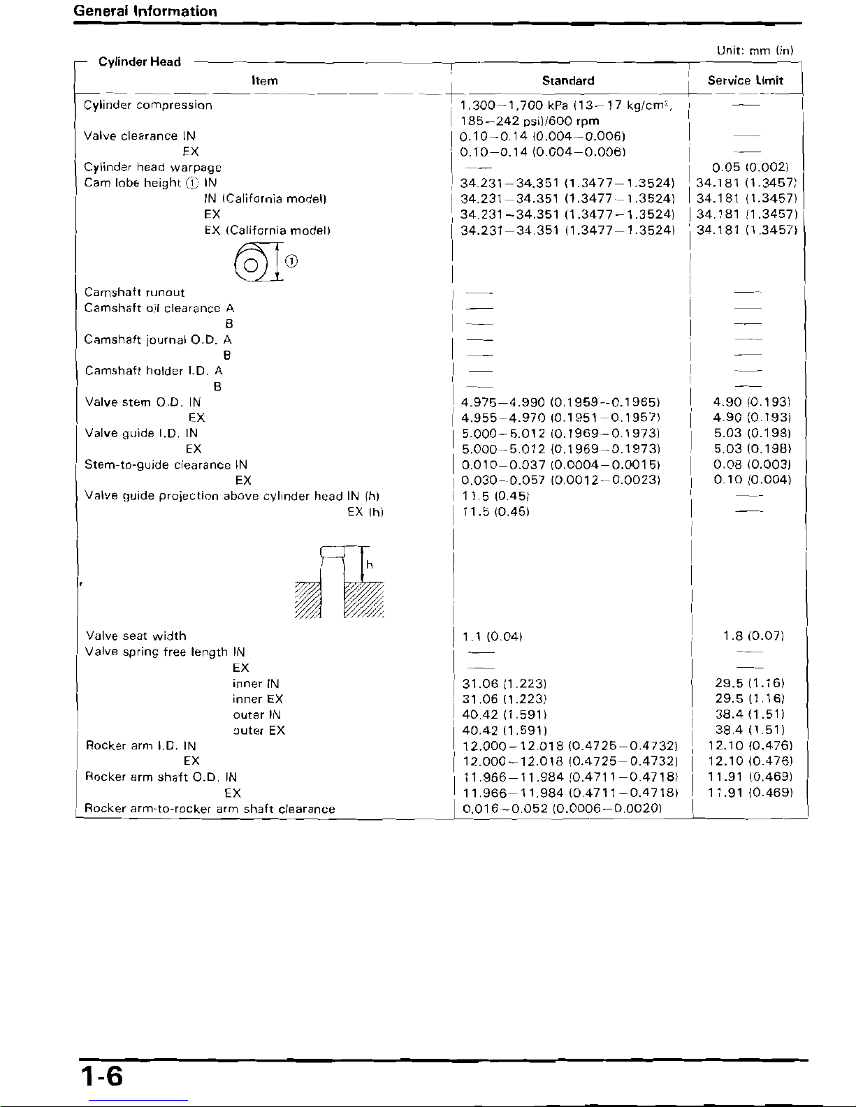
General Information
Unit:
mm
lin)
Cylinder
He.d
I I
~
Item Standard
~
Service limit
Cylinder
compression--
--------
--
--+I~
1,300-1,700
kPa
113-
17
kg/cm
2 ,
I--~--
185-242
psil/600
rpm 1
Valve clearance IN
10.10
-0.1410.004-0.0061
--
EX
10.10-0.1410.004-0.0061
1
Cylinder head
warpage
.
--
I
0.05
10.0021
Cam lobe
height(i)/N
134.231-34.35111.3477-1.35241
34.18111.34571
IN ICalifornia model) I
34.231-34.351
11.3477-1.35241
I
34.181
11.34571
EX
34.231-34.351
[1.3477-1.3524i
1
34.181
11.34571
EX
ICaliforni.
model)
134.231-34.35111.3477-1.35241
134.18111.34571
@lCD
i
Camshaft
run
out
Camshaft
oil
clearance
A
I
B
I
Camshaft journal
0.0.
A
B I
Camshaft
holder 1.0. A
B
1
Valve stem
0.0.
IN
I
4.975-4.99010.1
959-0.1
9651
4.9010.1931
EX
I
4.955-4.970
10.1951-0.19571
49010.1931
Valve guide 1.0.
IN
I
5000-
5.012
10.1969-0.19731
5.03
10.198!
EX
5.000-
5.012
10.1969 -O.
19731
5.03
10.1
981
Stem-ta-guide
clearance
IN
I
0.010-0.037
10.0004-
0.00151
0.0810.0031
EX
0.030-0.057
10.0012-0.00231
0.10
10.0041
Valve
guide projection above cylinder head
IN
{hl
I
11.510,451
EX Ihi
I
11.5
10,451
I
h
'j/
~W
::::~~
Valve seat width
1.1 10.041
1.8
10.071
Valve
spring free length IN
EX
inner
IN
31.0611.2231
29.511.161
inner
EX
31.0611.2231
29.511.161
outer
IN
40,42
11.5911
38,411.511
outer
EX
40,4211.5911
38.411.511
Rocker arm
1.0.
IN
12.000-12.018
10,4725-0.47321
12.1010.4761
EX
12.000-12.01810,4725-0.47321
12.1010.4761
Rocker arm
shafIO.D.
IN
11.966-11.98410,4711-0,47181
11.91 10.4691
EX
11.966-11.98410.4711-0,47181
11.91
10.4691
e..:.~r
a::.n:..:c..:e
L..::0~.
0:.:1
6 -
0.052
(0.0006 -0.0020)
~
--.J
L-R_o.:.ck.:.e:..r.:.a:..r:..m:..-
t:..:o_-r:..:o:..:c:..:ke:cr_a:cr~m~sh~a:cf:..'
..:c:..:1
1-6
----
--
--
I
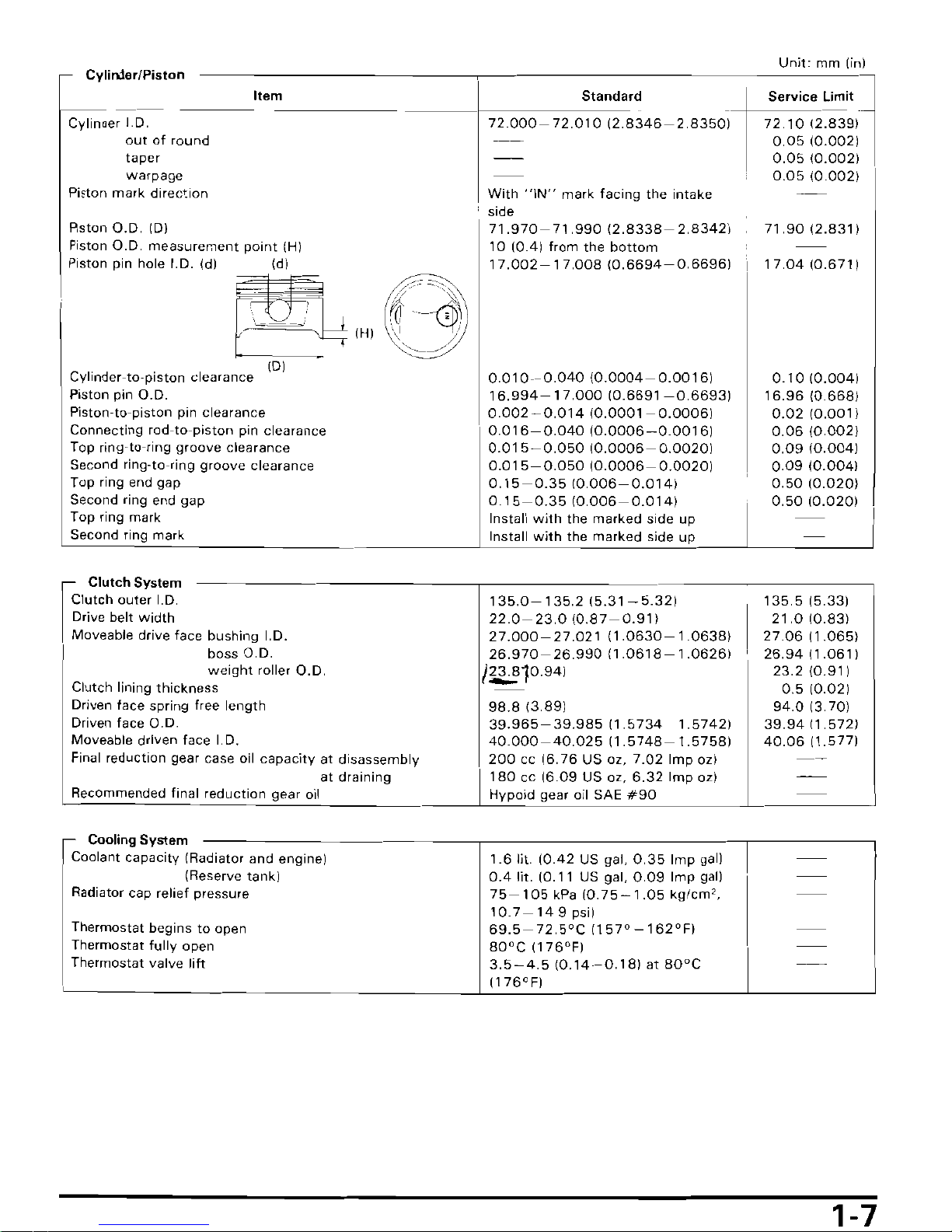
Unit: mm
(in)
- Cylin:ter/Piston
Item
Standard Service Limit
ttl
Cylinller
J.D.
out
of round
taper
warpage
Pi~ton
mark direction
Rston
a.D.
IDI
Piston
O.D.
measurement
point
(H)
Piston pin hole I.D. Idl Idl
~
~IHI
d'
IDI
C
I
·
er-to-plston clearance Yin
Piston pin
O.D.
Piston-to-piston
pin
clearance
Connecting rod-to-piston
pin
clearance
Top ring-to-ring groove clearance
Second ring-to-ring groove clearance
Top ring end gap
Second ring end gap
Top ring mark
Second ring mark
Clutch System
Clutch outer
I.
D.
Drive belt width
Moveable drive face bushing 1.0.
boss
0.0.
weight
roller
0.0.
Clutch lining thickness
Driven face spring free length
Driven face
0.0.
Moveable driven face
I.
D.
Final reduction gear case
oil
capacity at disassembly
at draining
Recommended final reduction gear
oil
r
Cooling System
Coolant capacity (Radiator and engine)
(Reserve tank)
Radiator cap relief pressure
Thermostat begins to open
Thermostat fully open
Thermostat valve lift
72.000-72.01012.8346-2.8350"1
-
With
"IN"
mark facing the intake
side
71.970-71.99012.8338-2.83421
10
10AI from
the
bottom
17.002-17.00810.6694-0.66961
0.010-0.040
10.0004-0.00161
16.994-17.00010.6691-0.66931
0.002--0.01410.0001-0.00061
0.016-0.04010.0006-0.00161
0.015-0.05010.0006-0.00201
0.015-0.05010.0006-0.00201
0.15-0.3510006-0.0141
0.15-0.3510.006-0.0141
Install
with
the marked side up
Install
with
the marked side up
135.0-135.2
15.31 - 5.321
22.0-23.010.87-0.911
27.000-27.02111.0630-1.06381
26.970-2699011.0618-1.06261
1~10941
98.8
13.891
39.965-
39.98511.5734
1.57421
40.000-40.02511.5748-1.57581
200
ee
[6.76
US oz,
7.02
Imp ozl
180
ee
[6.09
US oz,
6.32
Imp ozl
Hypoid gear
oil
SAE
#90
1.6
lit.
[OA2
US
gal.
0.35
Imp gall
OA
lit. [0.11
US
gal,
0.09
Imp gall
75-105
kPa
[0.75-1.05
kg/em',
10.7-14.9
psil
69.5-72.5'C
1157'
-162'FI
80'C
1176'FI
3.5-4510.14-0.181
at
80'C
[176'FI
721012.839)-
0.0510.0021
0.05
10.0021
,
0.05
10.0021
71.9012.831
I
17.0410.6711
0.10
10.0041
16.96
106681
0.02
10.0011
0.06
10.0021
0.09
10.0041
0.09
10.0041
0.5010.0201
0.50
10.0201
135.515.331
21.0
10.831
27.0611.0651
26.9411.0611
23.210.911
0.5
[0.021
94.0
[3.701
39.9411.5721
40.06
[1.5771
I
I,
1-7
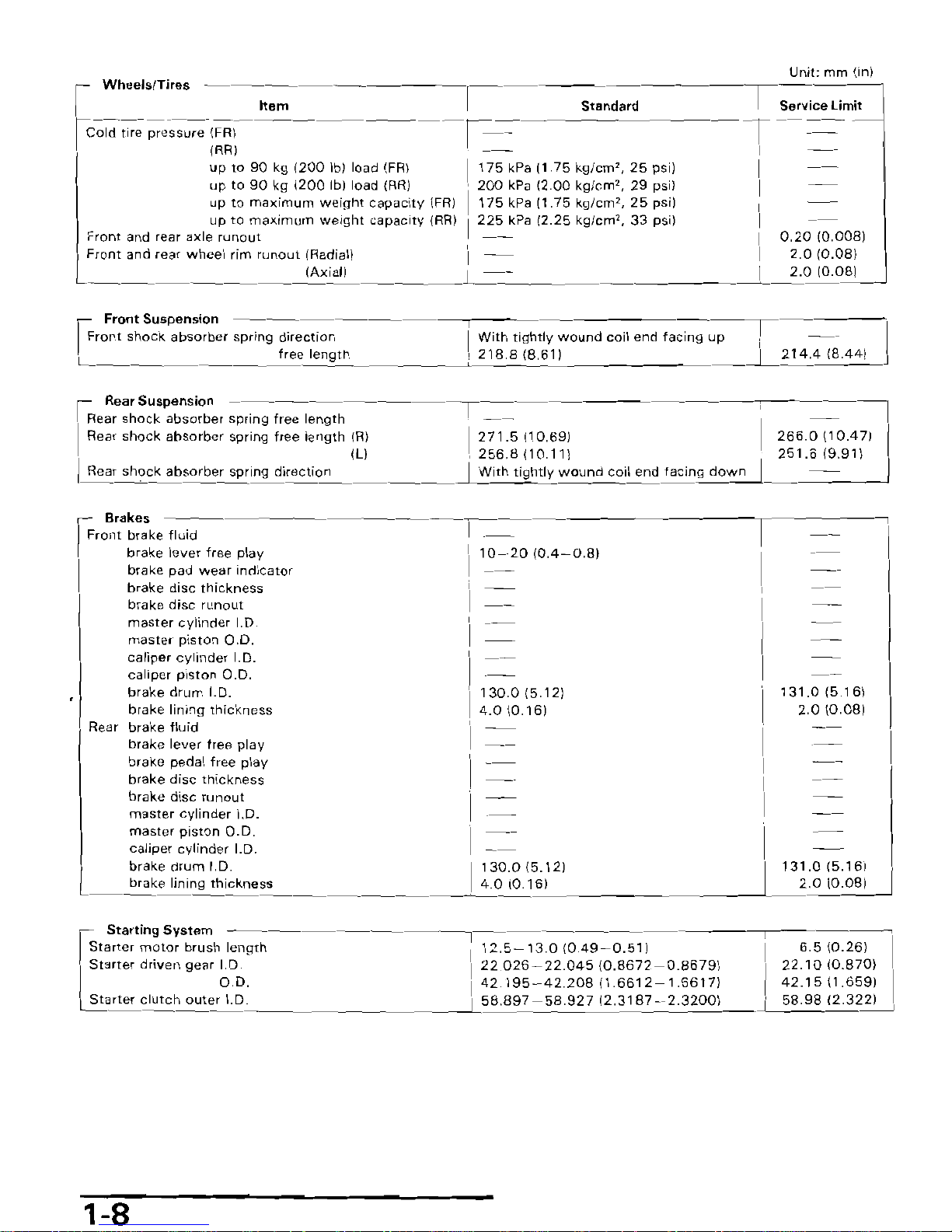
Unit: mm lin)
Wheels/Tires
Item
Standard
Service
limit
Cold
tire
preSS~(FR)-~-----------r--=-
T-
~
IRRJ
~-
up
to
90
kg
1200
Iblload
IFRI
1175
kPa 11.75
kg/cm',
25
psil
up
to
90
kg
1200
Ibl
load
IRRI
200
kPa 12.00
kg/cm',
29
psi!
\
up to
maximum
weight capacity
(FR) \ 175
kPa
\1.75
kg/cm
2
,
25
psi)
up to
maximum
weight capacity
(RR) I 225
kPa
(2.25
kg/cm
2
,
33
psi)
I
Front and rear axle runaut
0.2010.0081
Front and rear wheel rim runout (Radial) \
I
2.0
(0.081
IAxiall
I
I
2.010.081
Front Suspension
Front shock absorber spring direction
With
tightly wound coil end facing up
~_~_~
f_re_e_l_e_ngc_t_h
__
~
~
218.8
1.-=8::.6=--lccl
-"--__2_1_4_A_18_._4_4c-I
--'
Rear Suspension
T---
Rear shock absorber spring free length \
Rear shock absorber spring free length
\R}
1271.5
\10.69}
2660
(100471
ILl
256.8110.111
251.619.911
Rear sh?ck absorber
sprlng_d_i_re_c_t_i
o_n
~
~LW:..i-=t::h-:t"i
g"h::t"ly_wLo::L:..,":..dLco,_il
::e::n_d_t::a_c_in-'g=-d::o_w_n_-'-
-'
Brakes
Front brake fluid
brake lever free play
10-2010A-0.BI
brake pad
wear
indicator
brake disc thickness
brake disc runout
master cylinder
1.
D.
master piston
0.0.
caliper cylinder
I.
O.
caliper piston
0.0.
brake drum 1.0.
130015.121
131.015.161
brake lining thickness
4.0
10.161
2.010.081
Rear brake fluid
brake lever free play
brake pedal free play
brake disc thickness
brake disc runout
master cylinder 1.0.
master piston
0.0.
caliper cylinder 1.0.
brake drum 1.0.
130.015.121
131.015.161
brake lining thickness
4.010.161
2.010.081
Starting
System
Starter
motor
brush length
112.5-13010049-0.511
6.510.261
Starter
driven
gear
I.D.
22.026-22.04510.8672-0.86791
22.1010.8701
00.
142.195-4220811.6612-166171
42.1511.6591
Starter
clutch
outer__I._D
------l.
58.897 -58.927
12.31 B7 -2__
.3_2_0_0-'1__--L_58_.
9_8.....:.12_._3_2_2_1-"
1-8
General
Information
Unit:
mm
(in)
r-
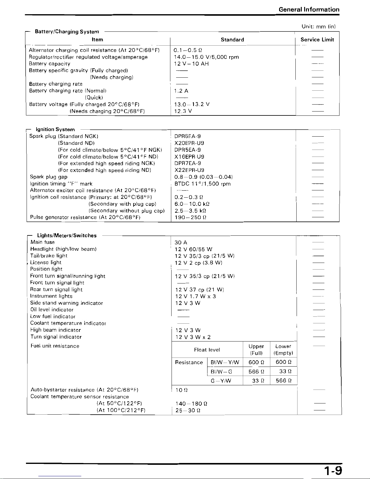
Battery/Charging
System
~
__
Item
_-+
Alternator charging coil resistance
(At
20 D C/68°F)
Regulator/rectifier regulated
voltage/amperage
Battery
capacity
Battery specific
gravity
(Fully charged)
(Needs charging)
Battery charging rate
Battery charging rate (Normal)
(Quickl
Battery voltage (Fully charged
20°C/68°F)
(Needs charging
20o CJ68°F)
S_t_a_n_d_a_'_d
---iL_
~_~rvice
Limit
0.1-0.5
n I
14.0
- 1
5.0 V/5,
000
rpm
12 V-10
AH
1.2
A
13.0-13.2
V
12.3
V
Ignition
System
-----------------,--------------------
------_
Spark plug (Standard NGKI
(Standard NDI
(For cold
climate/below
5°C/41°F
NGKI
(For cold
climate/below 5°C/41
°F NDI
(For extended high speed riding NGK}
(For extended high speed riding NO)
Spark plug gap
Ignition timing
"F"
mark
Alternator exciter coil resistance
(At
20o CJ68°Fl
Ignition coil resistance (Primary: at
20°C/68°F)
(Secondary
with
plug cap)
(Secondary
without
plug cap)
Pulse generator resistance
(At
20°C/68°F)
Lights/Meters/Switches
Main fuse
Headlight
(high/low
beaml
Tail/brake light
License light
Position light
Front turn signal/running light
Front turn signal light
Rear turn signal light
Instrument lights
Side stand warning indicator
Oil
level indicator
Low fuel indicator
Coolant temperature indicator
High beam indicator
Turn signal indicator
Fuel
unit resistance
Auto-bystarter resistance {At
20°C/68°F)
Coolant
temperature
sensor resistance
(At
50 0 C1122°FI
IAt
100°C/212°FI
DPR6EA·9
X20EPR·U9
DPR5EA·9
X16EPR·U9
DPR7EA-9
X22EPR-U9
0.8-0.9
(0.03-0.041
BTDC
11°/1
,500
rpm
I
0.2-0.3
Q
6.0-10.0
kQ
2.5-3.5
kQ
190-250
Q
30
A
12 V 60/55
W
12 V 35/3
cp
(21/5
WI
12
V 2 cp
(3.8
WI
12 V 35/3
cp
(21/5
WI
12 V
37
cp
121
WI
12V1.7Wx3
12
V 3 W
12
V 3 W
12V3Wx2
Float level
Resistance
hB'/W-Y/W
,
BI/W-G
G-Y/W
10
n
Upper
(Full)
600
Q
566
Q
33
[)
Lower
(Emptyl
600
Q
33
Q
566
[)
140-180
Q
25-30
Q
1-9
General
Information
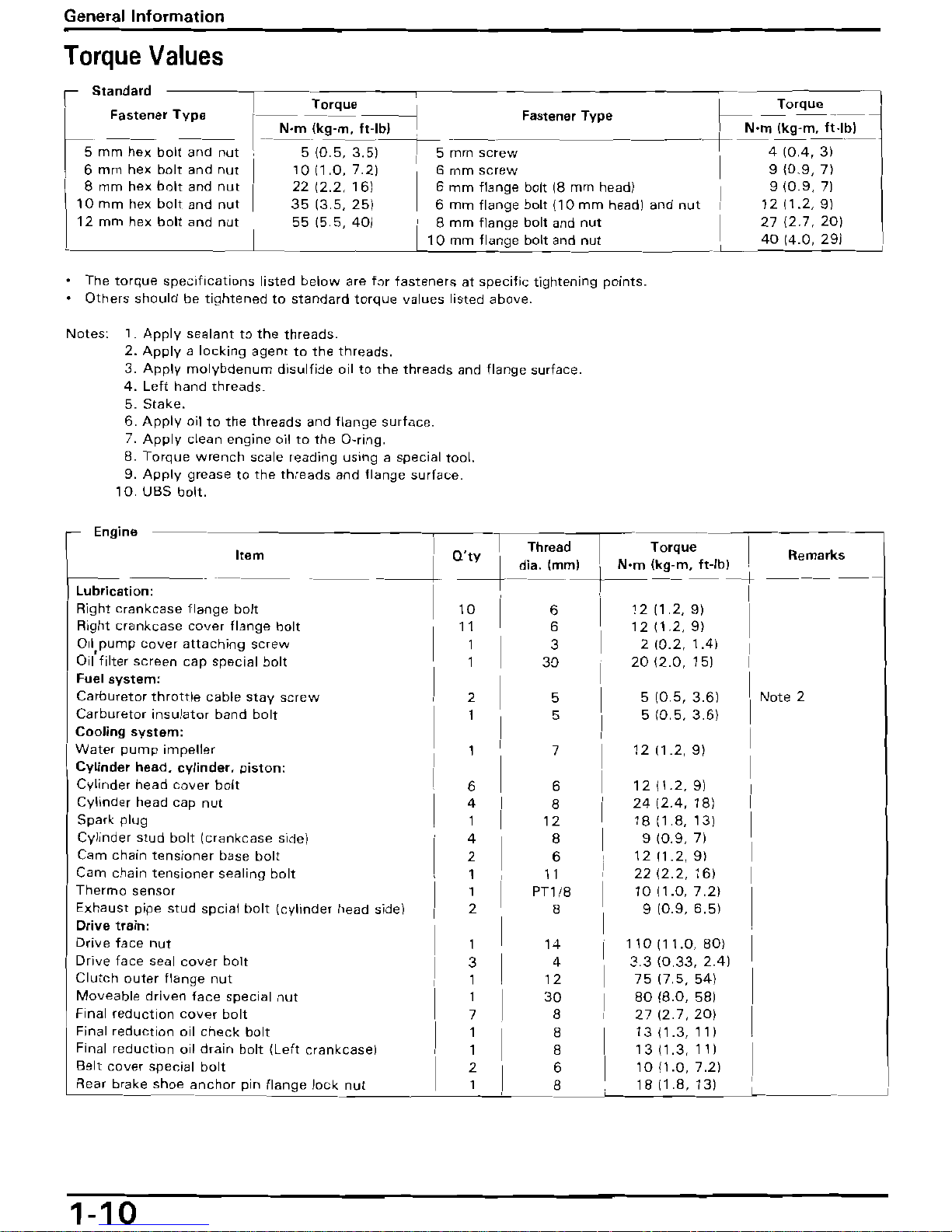
Torque
Values
Standard
1-
Torque
'I
I
Torque
Fastener
Type
L_
----
--_
Fastener
Type
f--
-
--
----
I
N'm
Ikg-m.
It-Ib)
" -+
N'm
Jkg-m---!t~b_l_
5
mm
hex
bolt
and
nut
,---S-{O.5,
i51--TS rnrn
sc~ew
--------
I 4 (004,
3)
6
mm
hex
bolt
and
nut
10
(1.0,
7.2)
6
mm
screw
9 {D.9,
7l
I
8
mm
hex
bnlt
and
nut
22 12.2.
161
6
mm
flange
bolt
18
mm
headl
910.9.
71
10
mm
hex
bolt
and
nut
3513,5.251
6
mm
flange
bolt
110
mm
head I and
nut
1211.2,91
12
mm
hex
bolt
and
nut
55
(5,5,
40)~mm
flange
bolt
and
nut
27
(2.7,
20)
I
10
mm
flange
bolt and
nut
40
14.0,
291
--~~---
The
torque
specifications
listed
below
are
for
tasteners
at
specific
tightening
points.
Others
should
be
tightened
to
standard
torque
values
listed
above.
Notes:
1.
Apply
sealant
to
the
threads.
2.
Apply a locking
agent
to
the
threads.
3.
Apply
molybdenum
disulfide
oil
to
the
threads
and
flange
surface.
4.
Left
hand
threads.
5.
Stake.
6.
Apply
oil
to
the
threads
and
flange
surface.
7.
Apply
clean
engine
oil
to
the
a-ring.
8.
Torque
wrench
scale
reading
using a special
tool.
9.
Apply
grease
to
the
threads
and
flange
surface.
10.
UBS
bolt.
\ Engine
Item
____ I ---l
Q'
I Threed
~+
di.~ml
Torque
I
N'm
(kg-m,
ft-Ibl
+--------t
Remarks
Lubrication:
I
Right
crankcase
flange
bolt
I
10
I
6
1211.2,91
Right
crankcase
cover
flange
bolt
I
11
I
6
1211,2,91
I
Oil
pump
cover
attaching
SCrew
oil'
filter
screen
cap
special
bolt
I
~
I
3
30
2 10.2. 1.41
20
12,0,
151
I
Fuel
system:
Carburetor
throttle
cable
stay
screw
I 2 I 5 5 10.5, 3.61
Note
2
Carburetor
insulator
band
bolt
5
510,5.3,61
Cooling
system:
I 1
'I
Water
pump
impeller
7
1211.2,91
Cylinder
head,
cylinder.
piston:
Cylinder
head
cover
bolt
I 6 I 6
1211.2.91
Cylinder
head
cap
nut
Spark
plug
I
~
I
8
12
24
12.4.
181
1811,8,131
Cylinder
stud
bolt
(crankcase
side)
B
910.9.71
Cam
chain
tensioner
base
bolt
~
I
6
1211.2,91
Cam
chain
tensioner
sealing
bolt
11
22 12,2,
161
Thermo
sensor
~
I
PTl/8
1011.0,7.21
Exhaust
pipe
stud
spcial
bolt
(cylinder
head side)
2
8
910.9.6.51
Drive
train:
Drive
face
nut
1
I
14
110111.0,801
Drive
face
seal
cover
bolt
Clutch
outer
flange
nut
3
1
I
4
12
33
10,33. 2.41
7517,5.541
Moveable
driven
face
special
nut
1
30
8018.0,
581
Final
reduction
cover
bolt
7
8
27127.201
Final
reduction
oil
check
bolt
1
8
1311.3,111
Final
reduction
oil
drain
bolt
(Left
crankcase)
1
8
1311,3,111
Belt
cover
special
bolt
2
6
1011.0,7.21
Rear
brake
shoe
anchor
pin
flange
lock
nut
1 8
1811.8.131
1-10

1-11
 Loading...