

Honda CG71505014H Owner's Manual

TABLE OF CONTENTS
1. SAFETY ........................................................................................................... 3
Regulations for using the machine safely
2. IDENTIFICATION OF THE MACHINE AND COMPONENTS ......................... 7
Explanations on how to identify the machine and its main components
3. UNP ACKING AND ASSEMBLY ...................................................................... 9
Explanations on how to remove the packing and on how to assemble
separated parts
4. CONTROLS AND INSTRUMENTS ............................................................... 14
Position and functions of all the controls
5. HOW TO USE THE MACHINE ..................................................................... 19
Provides indications for working efficiently and safely
5.1 Safety recommendations ........................................................................ 19
5.2 Why the safety devices cut in ................................................................. 19
5.3 Preliminary operations before starting work............................................ 21
5.4 Using the machine ................................................................................. 24
5.5 Using on slopes ...................................................................................... 32
5.6 Transporting ........................................................................................... 33
5.7 Advice on how to obtain a good cut ........................................................ 33
6. MAINTENANCE ............................................................................................ 35
All the information for maintaining the machine in peak efficiency
6.1 Safety recommendations ........................................................................ 35
6.2 Routine maintenance .............................................................................. 36
6.3 Checks and adjustments ........................................................................ 40
6.4 Dismantling and renewing parts ............................................................. 44
7. TROUBLESHOOTING .................................................................................. 46
A help in quickly resolving any problems
8. ACCESSORIES (OPTIONAL) ...................................................................... 49
A description of the accessories available for particular types of work
9. SPECIFICATIONS ......................................................................................... 50
A summary of the main specifications of your machine
10. ALPHABETICAL INDEX ............................................................................. 51
Where informations can be found
EN 2 TABLE OF CONTENTS

INTRODUCTION
Dear Customer,
thank you for having chosen one of our products. We hope that you will get com-
plete satisfaction from using your new lawn-tractor and that it will fully meet all
your expectations.
This manual has been compiled in order that you may get to know your machine
and to be able to use it safely and efficiently. Don’t forget that it forms an integral
part of the machine, so keep it handy so that it can be consulted at any time, and
pass it on to the purchaser if you resell the machine.
This new machine of yours has been designed and made in line with current
regulations, and is safe and reliable if used for cutting and collecting grass exactly
following the instructions given in this manual (proper usage). Using the machine
in any other way or ignoring the instructions for safe usage, maintenance and
repair is considered "incorrect usage" which will invalidate the guarantee, and
the manufacturer will decline all responsibility, placing the blame with the user for
damage or injury to himself or others in such cases.
Since the product is continually being improved, you may find slight differences
between your machine and the descriptions contained in this manual. Certain
modifications can be made to the machine without prior warning and without the
obligation to update the manual, although the essential safety and function characteristics will remain unaltered. In case of any doubts, do not hesitate to contact
your Dealer. And now enjoy your work!
AFTER-SALES SERVICE
This manual gives all the necessary instructions for using the machine and the
basic maintenance that may be carried out by the user.
For all information not contained here, contact your Dealer
EN 1INTRODUCTION

1. SAFETY
1.1 HOW TO READ THE MANUAL
Some paragraphs in the manual containing information of particular importance
for safety and operation are highlighted at various levels of emphasis, and signify
the following:
or These give details or further informa-
tion on what has already been said, and aim to prevent damage to the machine.
Non-observance will result in the risk of injury to oneself
or others.
Non-observance will result in the risk of serious injury or
death to oneself or others.
This manual describes various versions of the machine, which mainly differ in:
– type of transmission: with mechanical gear-change or with hydrostatic conti-
nuous speed adjustment;
– the inclusion of components or accessories which may not be available in
some areas;
– special equipments fitted.
The symbol highlights all differences in usage and is followed by the indica-
tion of the version to which it refers.
The symbol “ ☛ ” makes a reference to another part of the manual where further
information or clarification can be found.
Whenever a reference is made to a position on the machine
“front”, “back”, “left” or “right” hand side, this is determined by facing the direction of forward travel.
For all usage and maintenance operations on the engine or
the battery which are not described in this manual, consult the relevant manuals
which form an integral part of all the documentation supplied with the machine.
IMPORTANT
NOTE
➤
!
DANGER!
!
WARNING!
IMPORTANTNOTE
EN 3SAFETY

1.2 SAFETY REGULATIONS
(read carefully before using the machine)
A) TRAINING
1) Read the instructions carefully. Be familiar with the controls and the proper use of
the equipment.
2) Never allow children or people unfamiliar with these instructions to use the lawn-
mower. Local regulations can restrict the age of the operator.
3) Never mow while people, especially children, or pets are nearby.
4) Keep in mind that the operator or user is responsible for accidents or hazards
occurring to other people or their property.
5) Do not carry passengers.
6) All drivers should seek and obtain professional and practical instruction. Such
instruction should emphasise:
– the need for care and concentration when working with ride-on machines;
– control of a ride-on machine sliding on a slope will not be regained by the application of the brake. The main reasons for loss of control are:
– insufficient wheel grip;
– being driven too fast;
– inadequate braking;
– the type of machine is unsuitable for its task;
– lack of awareness of the effect of ground conditions, especially slopes;
– incorrect hitching and load distribution.
B) PREPARATION
1) While mowing, always wear substantial footwear and long trousers. Do not operate
the equipment when barefoot or wearing open sandals.
2) Thoroughly inspect the area where the equipment is to be used and remove all
objects which can be thrown by the machine.
3) DANGER! Petrol is highly flammable:
– store fuel in containers specifically designed for this purpose;
– refuel outdoors only and do not smoke while refuelling;
– add fuel before starting the engine. Never remove the cap of the fuel tank or add
petrol while the engine is running or when the engine is hot;
– If petrol is spilled, do not attempt to start the engine but move the machine away
from the area of spillage and avoid creating any source of ignition until the petrol
vapours have dissipated;
– replace all fuel tank and container caps securely.
4) Replace faulty silencers.
5) Before using, always visually inspect to see that the blades, blade bolts and cutter
assembly are not worn or damaged. Replace worn or damaged blades and bolts in
sets to preserve balance.
6) On multi-bladed machines, take care as rotating one blade can cause other blades
to rotate.
C) OPERATION
1) Do not operate the engine in a confined space where dangerous carbon monoxide
fumes can collect.
EN 4 SAFETY

2) Mow only in daylight or good artificial light.
3) Before attempting to start the engine, disengage all blade attachment clutches and
shift into neutral.
4) Do not use on slopes of more than 10° (17%).
5) Remember there is no such thing as a “safe” slope. Travel on grass slopes requires particular care. To guard against overturning:
– do not stop or start suddenly when going up or downhill;
– engage the clutch slowly and always keep the machine in gear, especially when travelling downhill;
– machine speeds should be kept low on slopes and during tight turns;
– stay alert for humps and hollows and other hidden hazards;
– never mow across the face of the slope.
6) Use care when pulling loads or using heavy equipment:
– use only approved drawbar hitch points;
– limit loads to those you can safely control;
– do not turn sharply. Use care when reversing;
7) Stop the blades rotating before crossing surfaces other than grass.
8) Never operate the machine with defective guards, or without safety protective devices in place.
9) Do not change the engine governor settings or overspeed the engine. Operating
the engine at excessive speed can increase the hazard of personal injury.
10) Before leaving the operator’s position:
– disengage the power take-off and lower the attachments;
– change into neutral and set the parking brake;
– stop the engine and remove the key.
11) Disengage drive to attachments, stop the engine and remove the ignition key:
– before clearing blockages or unclogging chutes;
– before cleaning, checking or working on the machine;
– after striking a foreign object. Inspect the machine for damage and make repairs
before restarting and operating the equipment;
– If the machine starts to vibrate abnormally (check immediately).
12) Disengage drive to blades when transporting or not in use.
13) Stop the engine and disengage drive to the attachment:
– before refuelling;
– before removing the grass catcher.
14) Reduce the throttle setting during engine run-out and, if the engine is provided
with a shut-off valve, turn the fuel off at the conclusion of mowing.
D) MAINTENANCE AND STORAGE
1) Keep all nuts, bolts and screws tight to be sure the equipment is in safe working
condition.
2) Never store the equipment with petrol in the tank inside a building where fumes
may reach an open flame or spark.
3) Allow the engine to cool before storing in any enclosure.
4) To reduce the fire hazard, keep the engine, silencer, battery compartment and
petrol storage area free of grass, leaves, or excessive grease.
5) Check the grass catcher frequently for wear or deterioration.
6) Replace worn or damaged parts for safety.
7) If the fuel tank has to be drained, this should be done outdoors.
8) On multi-bladed machines, take care as rotating one blade can cause other blades
to rotate.
9) When the machine is to be stored or left unattended, lower the cutting deck.
EN 5SAFETY
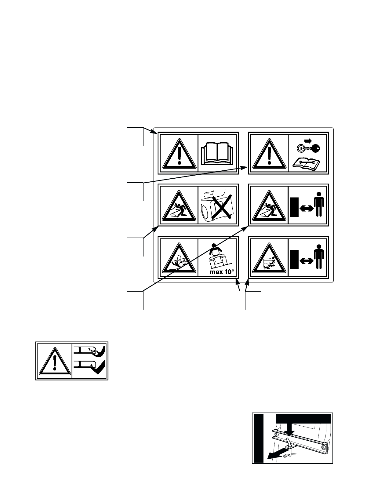
1.3 SAFETY DECALS
Your machine must be used with care. Therefore, decals have been placed on
the machine, to remind you pictorially of the main precautions to take during use.
These decals are to be considered an integral part of the machine.
If a decal should fall off or become illegible, contact your Retailer to replace it.
Their meaning is explained below.
1.4 REGULATIONS FOR TOWING
A kit for towing a small trailer is available on request.
This accessory is to be fitted as per the instructions provided. When using, do not exceed the recommended drawbar loads stated on the decal and follow the safety instructions, (☛ 1.2, C-6).
EN 6 SAFETY
Warning: Read the Operator’s
Manual before operating this
machine.
Warning: Disconnect the ignition key and read the instructions before carrying out any
repair or maintenance work.
Danger! Ejected objects: Do
not operate without either the
stone-guard or grass-catcher in
place.
Danger! Dismemberment: Make sure that chil-
dren stay clear of the
machine all the time when
engine is running.
Danger! Ejected objects: Keep
bystanders away.
Danger of cutting yourself. Blades in movement. Do not put
hands or feet near or under the opening of the cutting plate.
Danger! Machine rollover: Do not use this
machine on slopes greater then 10°.
max 245 N (25 kg)
max 980 N (100 kg)
2. IDENTIFICATION OF THE MACHINE AND COMPONENTS
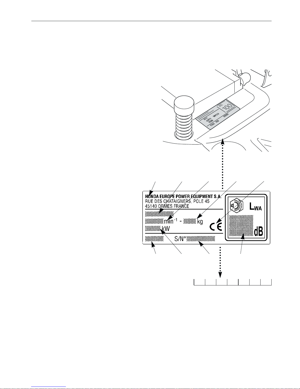
2.1 IDENTIFICATION OF THE MACHINE
The plate located near the battery housing has the essential data of each
machine.
The serial number (7) must be quoted
when you require technical assistance or
spare parts.
1. Acoustic power level according to
directive 2000/14/CE
2. Conformity mark according to
directive 98/37/EEC
3. Year of manufacture
4. Nominal power
5. Operating engine speed
in r.p.m
6. Type of machine
7. Serial number
8. Weight in kg
9. Name and address of
Manufacturer
2.2 IDENTIFICATION OF MAIN COMPONENTS
Various main components can be seen on the machine, and these have the following functions:
11. Cutting deck: this is the guard enclosing the rotating blades.
EN 7IDENTIFICATION OF THE MACHINE AND COMPONENTS
Note your machine serial number here
✍
3 4 7 1
69 5 8 2

12. Blades: these are what cut the grass. The wings at the ends help convey the
cut grass towards the collector channel.
13. Collector channel: this is the part connecting the cutting deck to the grasscatcher.
14. Grass-catcher: as well as collecting the grass cuttings, this is also a safety
element in that it stops any objects drawn up by the blades from being
thrown outside of the machine.
15. Stone-guard or deflector (available as optional part): this can be fitted in
place of the grass-catcher and prevents objects drawn up by the blades from
being thrown outside of the machine.
16. Engine: this moves the blades and drives the wheels. Its specifications and
regulations for use are described in a specific manual.
17. Battery: provides the energy for starting the engine. Its specifications and
regulations for use are described in a specific manual.
18. Driver seat: this is where the machine operator sits. It has a sensor for
detecting the presence of the operator which is a safety device.
19. Decals for regulations and safety: give reminders on the main provisions
for working safely, each of which is explained in chapter 1.
EN 8 IDENTIFICATION OF THE MACHINE AND COMPONENTS
11
12
14 13
18
17
16
19
15

3. UNP ACKING AND ASSEMBLY
For storage and transport reasons, some components of the machine are not
directly installed in the factory, but have to be assembled after their removal from
the packing. Final assembly is carried out by following these simple instructions.
The machine is supplied without engine oil or fuel. Before
starting up the engine, fill with oil and fuel following the instructions given in the
engine manual.
3.1 UNPACKING
When unpacking the machine, take care to gather all individual parts and fittings,
and do not damage the cutting deck when taking the machine off the base pallet.
The packing contents:
– the machine;
– the steering wheel;
– the seat;
– the grass-catcher brackets;
– the grass-catcher components;
– an envelope containing:
– the operator’s manuals and documents,
– the nuts and bolts including a pin for blocking the steering wheel,
– 2 starter keys and a spare 6.3 A fuse.
To prevent damaging the cutting deck when getting the
machine down from the pallet, lift it to the maximum height and be very careful.
For hydrostatic drive models: to make it easier to get the machine off the
pallet and to move it, the drive disengage lever should be put in position «B»
(
☛
4.33).
➤
NOTE
IMPORTANT
EN 9UNP ACKING AND ASSEMBLY
3.2 FITTING THE STEERING WHEEL
Put the machine on a flat surface and
straighten up the front wheels.
Fit the steering wheel (1) onto the protruding shaft (2) with the spokes directed
towards the seat.
Line up the hole in the steering wheel hub
with the hole in the shaft and insert the
pin supplied (3) using a hammer, ensuring
that the end comes completely through to
the opposite side.
To avoid damaging the steering wheel, use a punch of the
same size as the pin when hammering it in the last part
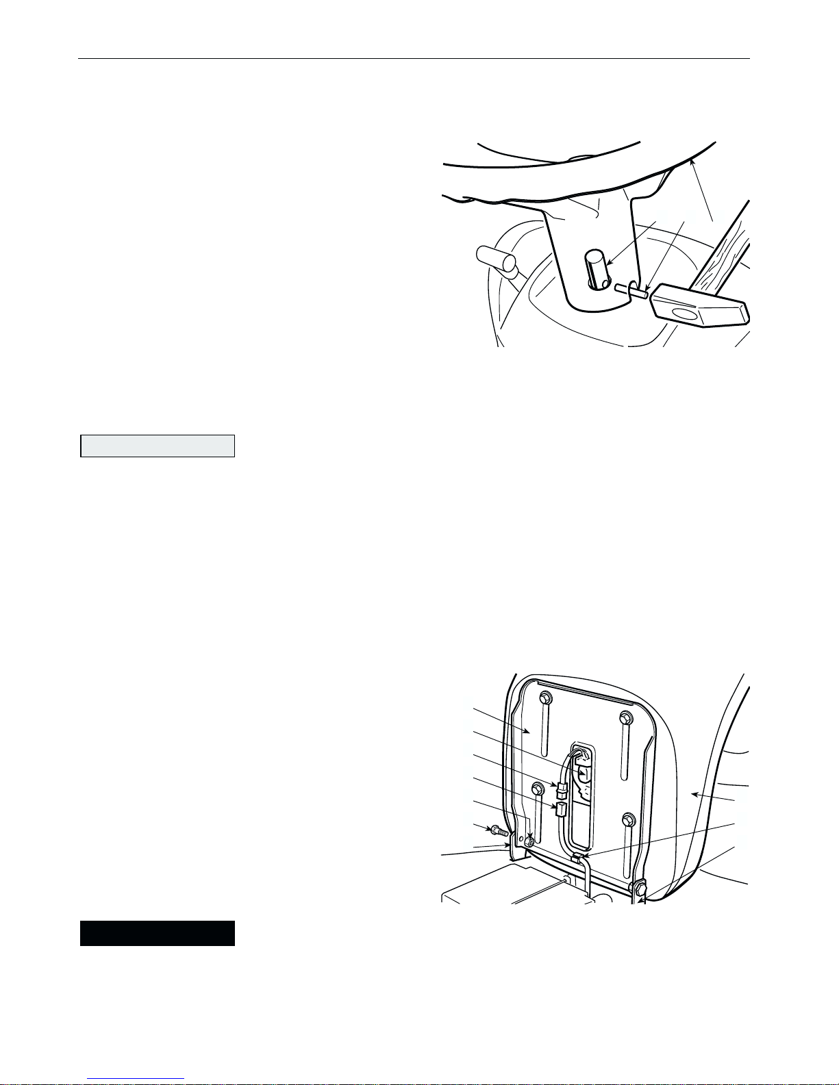
3.3 FITTING THE SEAT
The seat (1) is supplied attached to a
support bracket (2) on which has been fitted a micro-switch (3).
Fit the support bracket (4) using the screw
pins (5) supplied, fully tightening the relative nuts (6).
Connect the micro-switch socket (7) to the one coming
from the general wiring (8) to ensure that the safety device works, and
then fit the wire into the wire-holder (9).
!
ATTENTION!
NOTE
EN 10 UNP ACKING AND ASSEMBLY
2
3
7
8
6
5
1
9
4
4
132
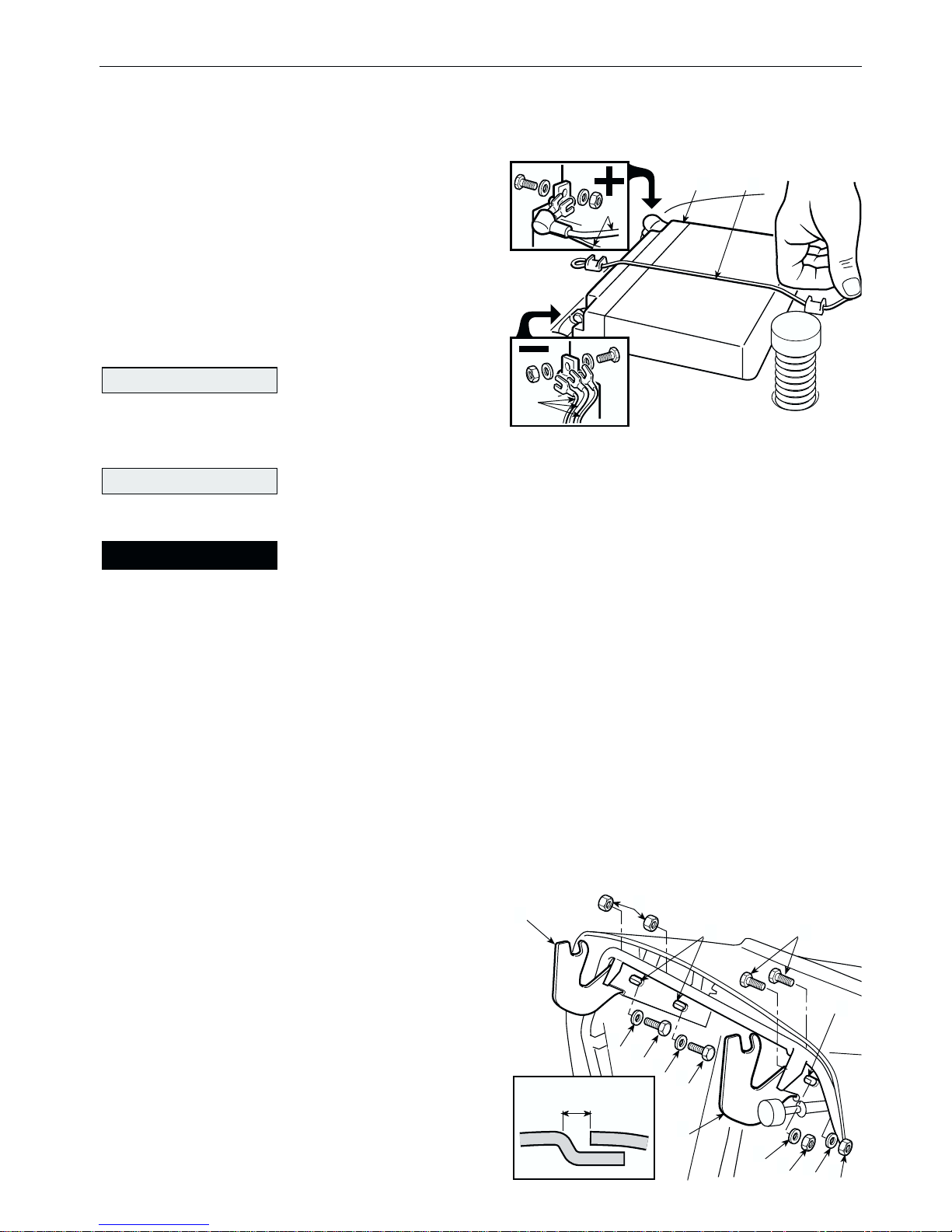
3.4 CONNECTING THE BATTERY
The battery (1) is situated under the seat
and is held in place by a spring (2).
Connect the two red cables (3) to the
positive terminal (+) and the three black
cables (4) to the negative terminal (–)
using the supplied screws and following
the illustrated sequence.
Always fully charge
the battery according to the instructions
in the battery’s manual (
☛
6.2.5).
To prevent the safety device in the electronics card from cutting in, never start the engine until the battery is fully charged!
Follow the battery manufacturer's instructions regarding
safe handling and disposal.
3.5 FITTING THE GRASS-CATCHER BRACKETS
Fit the two supports (1) and (2) on the rear plate, using the supplied screws (3),
washers (4) and nuts (5), exactly following the sequence shown.
Position the screws in the centre of the slots (6) without fully tightening.
Hook on the grass-catcher to the supports, checking that there is an even spa-
cing of 6 to 8 mm between the two plastic
covers.
This makes it possible for the grass-catcher to rotate properly when being emptied, but still prevents grass cuttings from
escaping.
To get the correct spacing, adjust the
position of the fastenings or the supports
in relation to the slots (6), then fully tighten the screws (3).
!
WARNING!
IMPORTANT
IMPORTANT
EN 11UNP ACKING AND ASSEMBLY
3
1
2
5
4
3
4
3
4
5
4
5
6
6
6 ÷ 8 mm
3
1 2
4
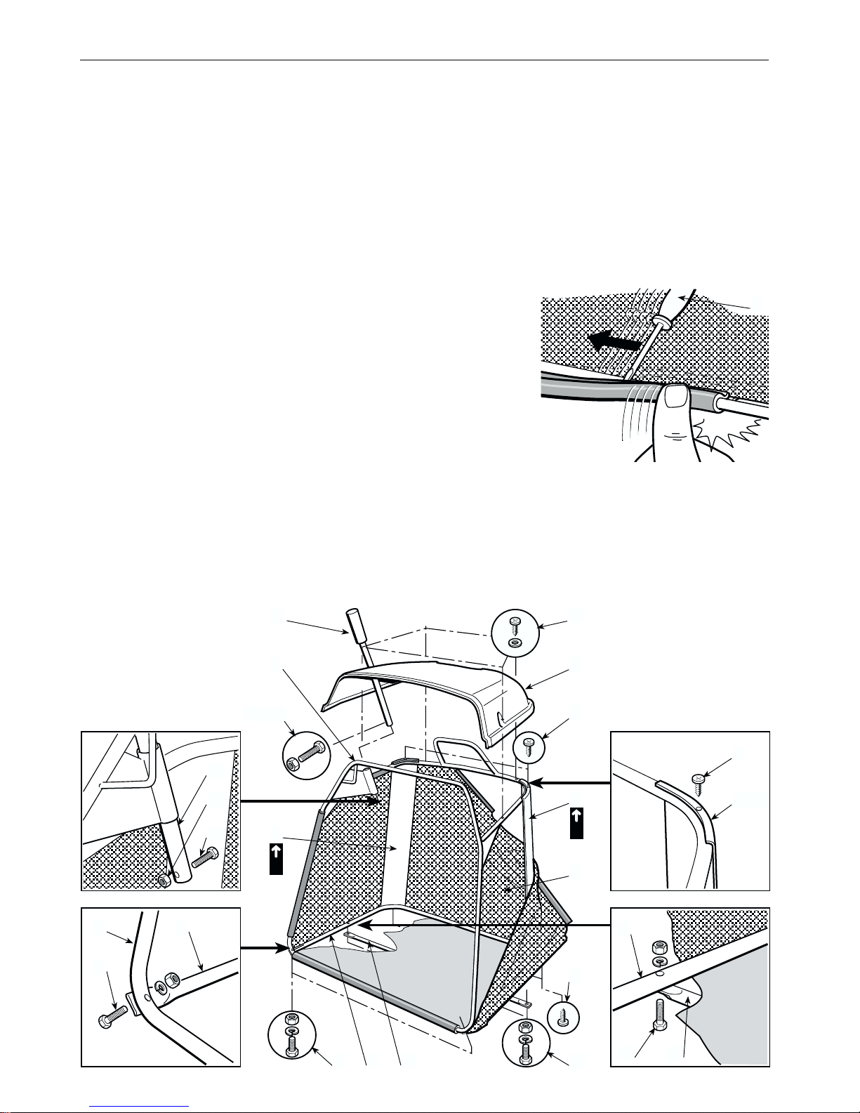
3.6 GRASS-CA TCHER ASSEMBLY
The grass-catcher is assembled in four stages:
A) First of all assemble the frame, joining the upper part (1) to the lower part (2)
using the supplied screws and nuts (3) as shown. Position the angle plates (4)
and (5), making sure that they are for the right (R) and left (L), sides, and
attach them to the frame using the four self-threading screws (6).
B) Insert the frame in the canvas cover (7) making
sure it is correctly positioned on the base perimeter.
Hook the plastic profiles onto the frame tubes with the
aid of a screw-driver (8).
C) Assembly the cover (9) on the upper frame by
means of the self-threading screws (10).
D) Attach the stiffening bar (11) under the frame with screws and nuts (12) keeping the flat part turned towards the canvas. Insert the emptying lever (13) in its
position and put in the limit stop screw (14) with its nut (15).
EN 12 UNP ACKING AND ASSEMBLY
R
10
9
6
5
6
12
13
14 -15
4
3 2 11
1
L
6
14
13
4 - 5
2
12 11
15
1 2
3
7
C
L
A
K
8
EN 13UNP ACKING AND ASSEMBLY
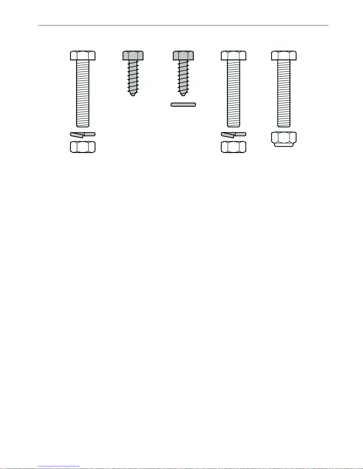
3 6 10 12 14 - 15
(x 2) (x 4) (x 4) (x 2)
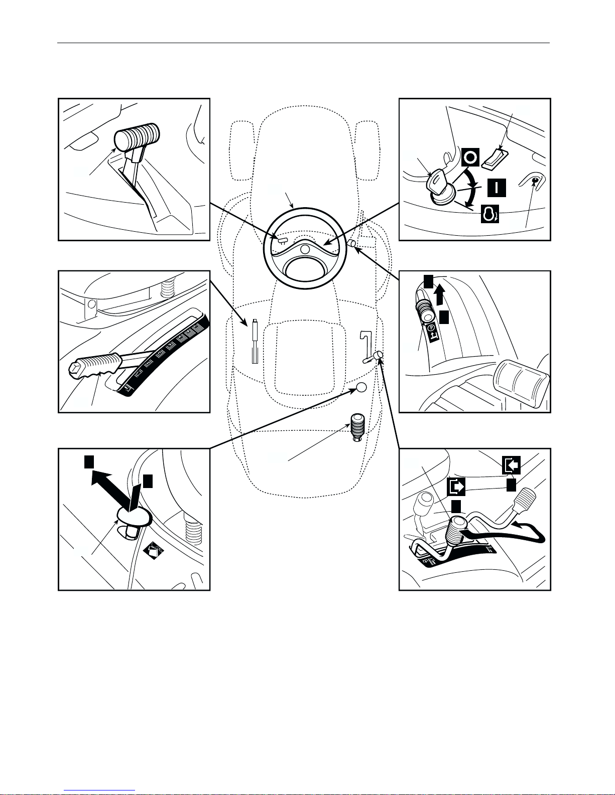
4. CONTROLS AND INSTRUMENTS
4.1 STEERING WHEEL
Turns the front wheels.
4.2 A
CCELERATOR LEVER
Regulates the engine's r.p.m. The positions are indicated on a plate showing the
EN 14 CONTROLS AND INSTRUMENTS
4.2
4.8
4.5
4.3
4.6
B
A
4.4
A
B
4.9
B
A
4.7
4.10
4.1

EN 15CONTROLS AND INSTRUMENTS
following symbols:
«CHOKE» for starting from cold;
«SLOW» for minimum engine speed;
«FAST» for maximum engine speed.
– The «CHOKE» position enriches the mixture so must only be used for the time
necessary when starting from cold.
– When moving from one area to another, put the lever in a position between
«SLOW» and «FAST».
– When cutting, go to the «FAST» position.
4.3 K
EY IGNITION SWITCH
This key operated control has three positions:
«OFF» everything is switched off;
«ON» activates electric power;
«START» engages the starter motor.
On being released at the «START» position, the key will automatically return to
«ON».
4.4 P
ARKING BRAKE LEVER
This lever is to stop the machine from moving when it has been parked. There
are two positions:
«A» = Brake off
«B» = Brake engaged
– The brake is engaged by fully pressing the pedal (4.21 or 4.31) and moving the
lever to position «B». When you take your foot off the pedal it will be blocked
by the lever in the down position.
– To disengage the parking brake, press the pedal (4.21 or 4.31). The lever will
return to position «A».

4.5 LIGHT SWITCH
For turning on the lights when the key (4.3) is in the «ON» position.
4.6 P
ILOT LAMP AND AUDIBLE WARNING
This light comes on when the key (4.3) is in the «ON» position and remains constantly lit while the machine is operating.
– When it starts flashing this means that the engine is being prevented from star-
ting (☛ 5.2).
– The audible warning indicates that the grass-catcher is full (☛ 5.4.6).
4.7 B
LADE ENGAGEMENT AND BRAKE CONTROL
The lever has two positions, as shown on the label:
«A» = Blades disengaged
«B» = Blades engaged
– If the blades are engaged when safety conditions have not been complied with,
the engine shuts down and cannot be restarted (☛ 5.2).
– On disengaging the blades (position «A»), a brake is simultaneously activated
which stops their rotation in few seconds.
4.8 C
UTTING HEIGHT ADJUSTING LEVER
There are seven positions for this lever, shown as «1» to «7» on the label, which
correspond to various heights of between 3 and 8 cm.
– To go from one height to another, press the release button at the end of the
lever.
4.9 G
RASS-CATCHER RELEASE BUTTON
This button, when pressed and brought back to the position «A», releases the
lower hooking device for the grass-catcher so that it can be emptied.
In order to re-hook it, press the button again, returning it to the normal operating
position «B».
EN 16 CONTROLS AND INSTRUMENTS
 Loading...