

Page 1
INSTALLATION
http://www.HandA-Accessories.com
INSTRUCTIONS
Accessory Application Publications No.
CD CHANGER
ATTACHMENT KIT
INSIGHT
AII 23268
Issue Date
OCT 2001
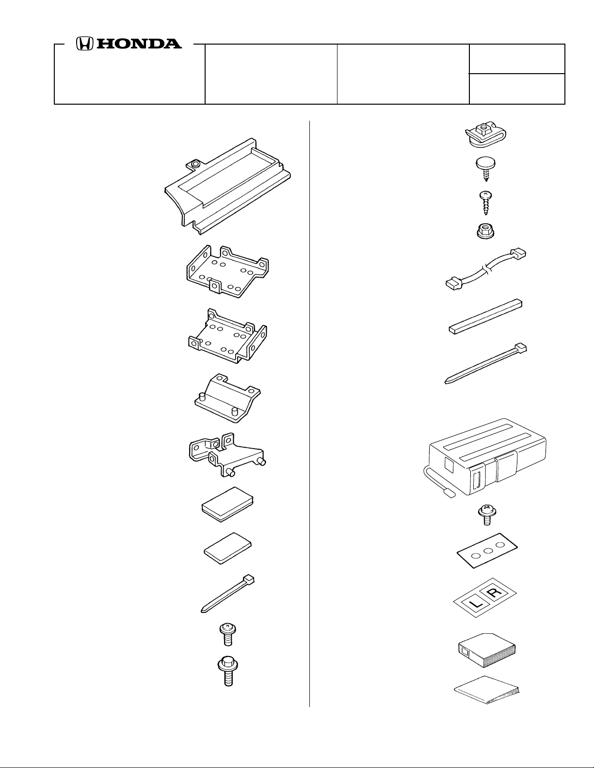
PARTS LIST
CD Changer Attachment Kit:
P/N 08B26-S3Y-100
CD changer trim
Front bracket
Rear bracket
Front base br acke t
4 Clip nuts
2 Clips
4 Self-tapping screws
4 Flange nuts
Bus cable
2 Spacers
5 Long wire ties
(4 not used)
Rear base bracket
6 EPT sealers
10 Cushion tapes
13 Short wire ties
(1 not used)
8 Washer-screws, 4 x 8 mm
4 Washer-bolts, 6 x 16 mm
CD Changer:
P/N 08A26-1B1-100
CD changer
4 Washer-screws, 4 x 6 mm
(Not used)
Adhesive seal sheet
Locking covers
CD magazine
Owner’s Manual
© 2001 American Honda Motor Co., Inc - All Rights Reserved. AII 23268 (0110) 1 of 10
Y0599D
08B26-S3Y-1000-91
Page 2
TOOLS AND SUPPLIES REQUIRED
#2 Phillips screwdriver
Flat-tip screwdriver
Stubby Phillips screwdriver
10 mm Combination wrench
Ratchet
10 mm Socket
Diagonal cutters
Utility knife
Tape measure
Gloves
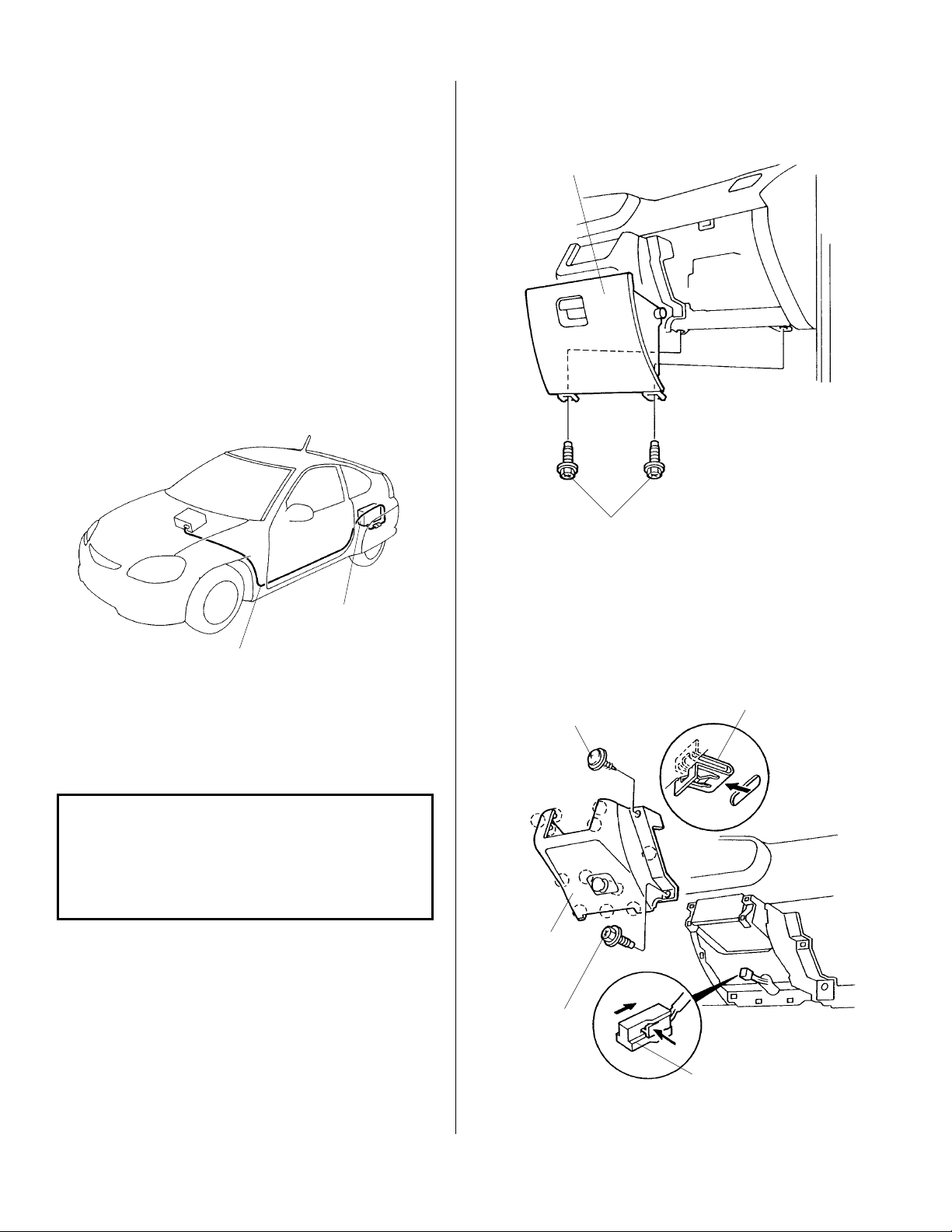
Illustration of the CD Changer Installed on the
Vehicle
3. Remove the two bolts that fasten the glove box,
and remove the glove box.
GLOVE BOX
BOLTS
CD CHANGER
(sold separately)
BUS CORD
INSTALLATION
Customer Information: The information in this
installation instruction is intended for use only by
skilled technicians who have the proper tools,
equipment, and training to correctly and safely add
equipment to your vehicle . These procedures should
not be attempted by “do-it-yourselfers.”
1. Write down the frequencies for the radio station
preset buttons.
2. Disconnect the negative cable from the battery.
4. Remove the center lower cover by removing the
two screws, releasing the 11 clips, and
disconnecting the connector.
SELF-TAPPING
SCREW
CENTER
LOWER
COVER
SCREW
CLIP
CONNECTOR
2 of 10 AII 23268 (0110) © 2001 American Honda Motor Co., Inc - All Rights Reserved.
Page 3
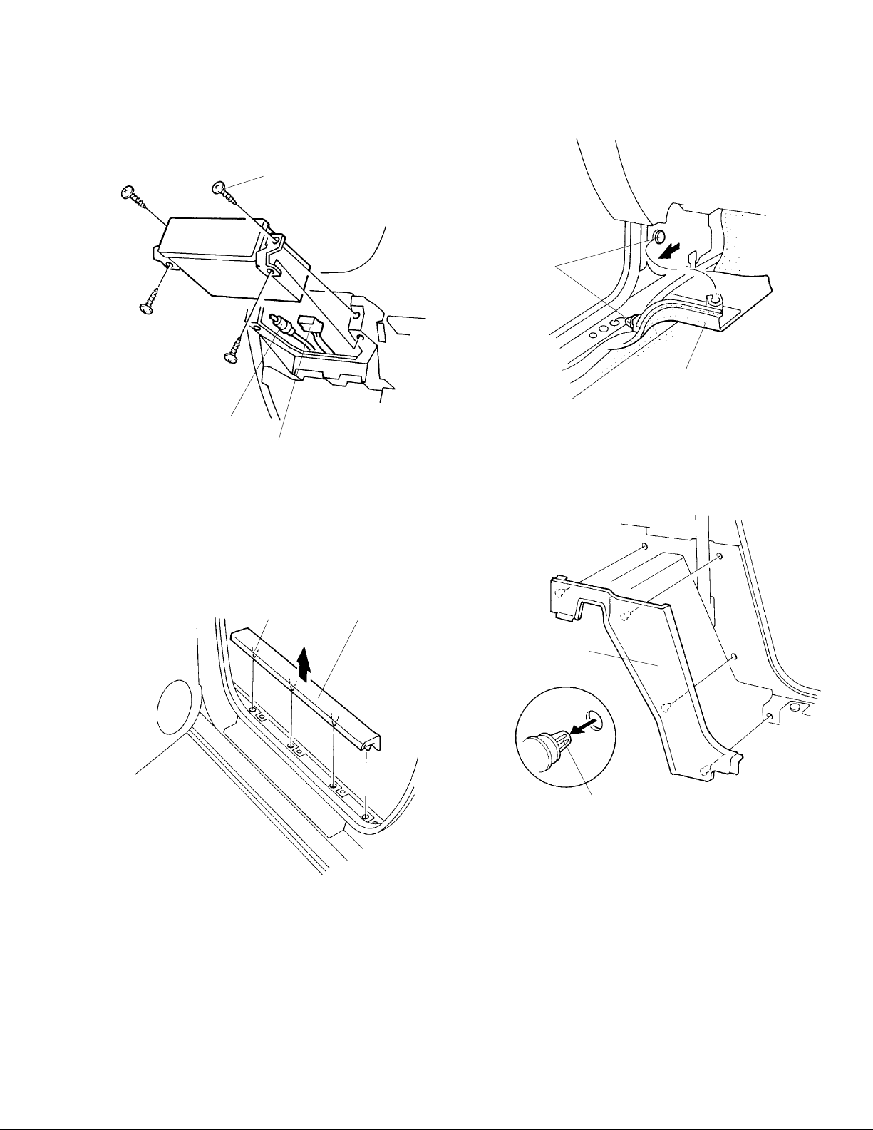
5. Remove the self-tapping screws that fasten the
radio, and pull the unit out tow ard you. Unplug the
vehicle harness connector and the antenna lead
from the rear of the radio.
SELF-TAPPING
SCREW
ANTENNA
LEAD
VEHICLE HARNESS
CONNECTOR
7. Detach the clips, and pull the driver's side cowl
carpet down and out of the way.
CLIPS
DRIVER'S SIDE
COWL CARPET
(Pull down and out
toward you.)
8. Remove the B-pillar lower trim panel (four
retaining clips). Take care not to damage the
retaining clips.
6. Remove the driver's door sill trim (four retaining
clips).
CLIP
DRIVER'S DOOR
SILL TRIM
B-PILLAR
LOWER TRIM
PANEL
RETAINING
CLIP
© 2001 American Honda Motor Co., Inc - All Rights Reserved. AII 23268 (0110) 3 of 10
Page 4
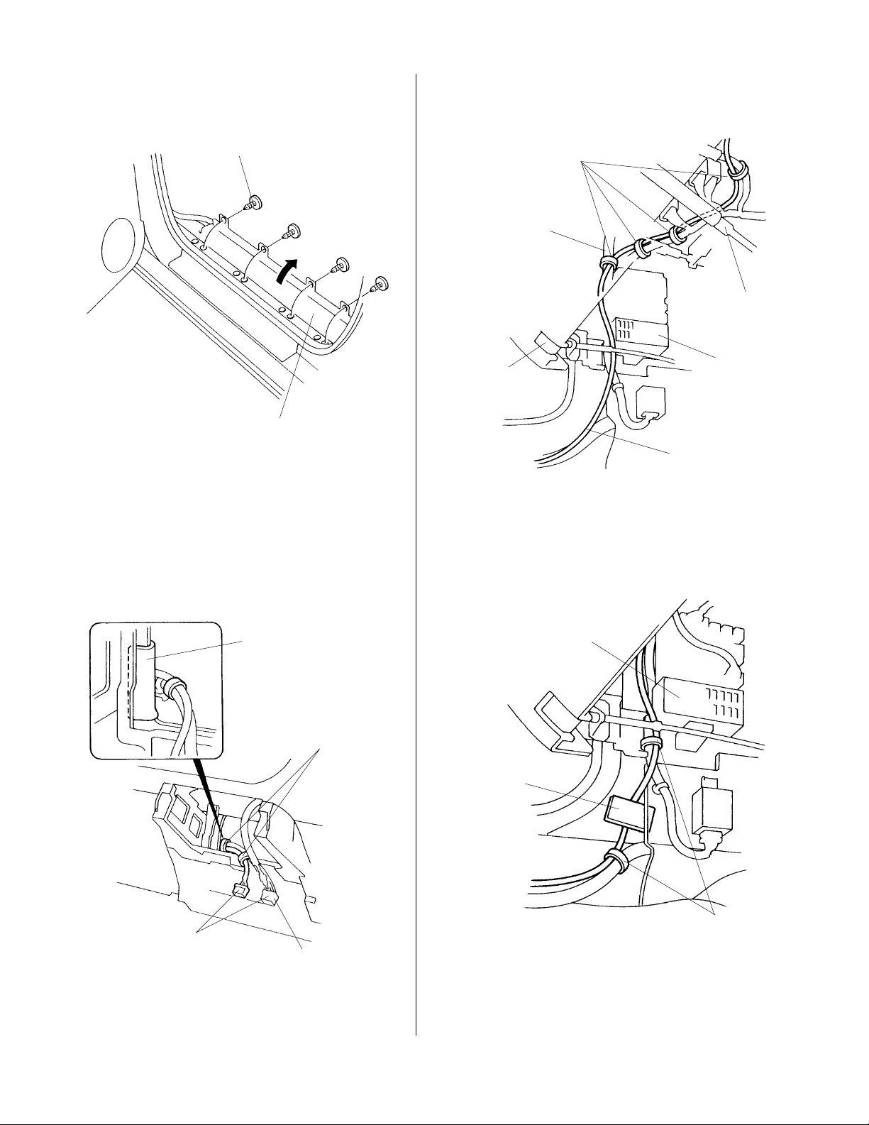
9. Remove the four expansion clips that fasten the
floor carpet, and fold the carpet down and out of
the way.
12. Route the BUS cable above the steering shaft,
and secure it to the vehicle harness with four
short wire ties in the areas shown.
EXPANSION
CLIP
FLOOR
CARPET
(Fold down.)
Routing the BUS Cable
10. Route one end of the BUS cable up under the
dashboard, and out the radio opening. P osition the
BUS cable connector alongside the radio
connector; then secure the BUS cable and the
vehicle harness with two short wire ties in the
areas shown.
SHORT
WIRE TIES
VEHICLE
HARNESS
STEERING
SHAFT
HOOD
OPENER
BUS
CABLE
FUSE BOX
13. Route the BUS cable down alongside the fuse
box, and secure it to the body panel with one
cushion tape. Secure the BUS cable to the vehicle
harness with the two short wire ties.
EPT SEALER
SHORT
WIRE TIES
(Position the BUS cable
connector flush with
the radio connector.)
RADIO
CONNECTOR
11. Attach a piece of EPT sealer to the dash support
to protect the BUS cable.
FUSE
BOX
CUSHION
TAPE
SHORT
WIRE TIES
4 of 10 AII 23268 (0110) © 2001 American Honda Motor Co., Inc - All Rights Reserved.
Page 5

14. Continue routing the BUS cable toward the rear
of the vehicle. Measure 35 mm below the door
opening, and secure the BUS cable to the body
with four cushion tapes.
18. Remove the rear side trim panel (three
expansion clips).
REAR SIDE
TRIM PANEL
EXPANSION
CLIP
SHORT
WIRE TIE
VEHICLE
HARNESS
35 mm
CUSHION
TAPES
15. Secure the BUS cable to the vehicle harness
with one short wire tie in the area shown.
16. Open the tailgate, and remove the cargo floor
mat.
CARGO FLOOR MAT
TAILGATE
WASHER-BOLT
LEFT TRUNK
SIDE BOARD
RELAY
19. Remove the left trunk side board by pulling out
on the back and toward you.
20. Locate the relay mounted to the lower trunk panel.
Remove the washer-bolt to free the relay.
21. Remove the middle bulkhead cover (pry out the
seven screw covers, and remove the seven
screws).
CARGO BOX
17. Remove the cargo box.
MIDDLE BULKHEAD
COVER
SELF-TAPPING
SCREW
SCREW
COVER
© 2001 American Honda Motor Co., Inc - All Rights Reserved. AII 23268 (0110) 5 of 10
Page 6

22. Remove the three clips, and fold down the top
portion of the middle carpet. If the v ehicle y ou are
working on is equipped with rear speakers,
remove the speakers and rear speaker holders.
SPEAKER
HOLDER
SCREW
CLIP
FLOOR
CARPET
(Turn over.)
24. Attach one cushion tape around the lower edge
of the hole in the inner panel; then route the BUS
cable toward the rear over the cushion tape.
Secure the BUS cable to the inner panel with
additional cushion tape.
BUS CABLE
CUSHION TAPE
25. Route the BUS cable down, and secure it to the
trunk panel with two cushion tapes.
CUSHION TAPE
CLIP
23. Continue routing the BUS cable toward the rear
of the vehicle alongside the vehicle harness,
then up and out through the cutout in the area
shown. While wearing gloves to protect your
hands, reach through the speaker hole, and
secure the BUS cable to the vehicle harness
with four short wire ties in the areas shown.
CUTOUT
SPEAKER
HOLE
BUS CABLE
SHORT
WIRE TIES
6 of 10 AII 23268 (0110) © 2001 American Honda Motor Co., Inc - All Rights Reserved.
Page 7

Installing the CD Changer
26. Carefully unpack the CD changer. Remove the
three shipping clips, and discard the shipping
cover. Save the shipping clips for your customer
in the event the unit needs to be serviced.
SHIPPING CLIP
SHIPPING COVER
(Discard.)
ADHESIVE SEAL
27. Install an adhesive seal (included with the CD
changer kit) over each of the three clip holes.
LEFT LOCKING
COVER
(supplied with
CD Changer kit)
30. Position the front and rear brackets on the CD
changer, and install four 4 x 8 mm washerscrews into each bracket.
FRONT
BRACKET
CD CHANGER
REAR
BRACKET
4 x 8 mm
WASHERSCREW
4 x 8 mm
WASHER-SCREW
31. Using a utility knife, cut out the inside line of the
center area on the CD changer trim.
CD CHANGER
TRIM
OUTSIDE LINE
Do not cut here.
RIGHT LOCKING
COVER
FOR VERTICAL
INSTALLATION
SPRING ADJUSTING PIN
VERTICAL POSITION
(supplied with
CD Changer kit)
INSIDE LINE
Cut here.
Cut out.
28. Visually check the location of the spring
adjusting pins on both sides of the CD changer.
If the spring adjusting pins are not in the vertical
(V) position, move the pins to the vertical (V)
position with a small flat-tip screwdriver.
29. Remove the backing from the two adhesive
covers, and attach one cover to each side of the
CD changer. Align the two diagonally opposite
holes with the H and V positions.
© 2001 American Honda Motor Co., Inc - All Rights Reserved. AII 23268 (0110) 7 of 10
Page 8

32. Place the CD changer trim on the CD changer,
and install the four self-tapping screws.
35. Remove the vehicle harness clip from the hole in
the inner panel.
SELF-TAPPING
SCREWS
CD CHANGER TRIM
CD CHANGER
CLIP
SELF-TAPPING
SCREWS
CLIP NUT
33. Remove 40 to 50 mm of the adhesive backing
from the back of each spacer, and fold them
back. Position the spacers on the CD changer
against the CD changer trim; then carefully
remove the adhesive backings while holding the
spacers in place. Be careful not to tear the
adhesive backings.
SPACER
ADHESIVE
BACKING
CD CHANGER
EPT SEALER
CD CHANGER
TRIM
SPACERS
36. Slide one clip nut onto each of the four holes in
the inner panel.
37. Apply one EPT sealer to the left taillight harness.
LEFT TAILLIGHT
HARNESS
EPT SEALER
34. Wrap one EPT sealer around the connector from
the CD changer.
8 of 10 AII 23268 (0110) © 2001 American Honda Motor Co., Inc - All Rights Reserved.
Page 9

38. Cut one piece of EPT sealer in half. Attach the
halves to the rear clip nuts you installed in step
36.
EPT SEALER
42. Position the CD changer on the studs extending
from the front and rear base brackets, and install
the four flange nuts. Install the CD changer first
on the front bracket, then the rear bracket.
FRONT
BRACKET
STUDS
EPT SEALER
(Cut in half.)
REAR BASE
BRACKET
6 x 16 mm
WASHER-BOLT
FRONT
BASE
BRACKET
EPT
6 x 16 mm
WASHER-BOLT
SEALER
39. Position the rear base bra c ket on the clip nuts,
and install two 6 x 16 mm washer-bolts. Tighten
the bolts securely.
40. Position the front base bracket on the clip nuts
and install two 6 x 16 mm washer-bolts. Tighten
the bolts securely. Attach one EPT sealer over
the head of the lower bracket bolt.
REAR
BRACKET
STUDS
CD CHANGER
FLANGE
NUTS
43. Reinstall the relay that was removed in step 20.
44. Plug the BUS cable connector into the CD
changer.
BOLT (reused)
41. Push the clip of the vehicle wire harness
removed in step 35 into the hole in the rear base
bracket.
REAR BASE
BRACKET
BUS
CABLE
CD CHANGER CONNECTOR
VEHICLE
HARNESS
CLIP
© 2001 American Honda Motor Co., Inc - All Rights Reserved. AII 23268 (0110) 9 of 10
VEHICLE RELAY
Page 10

45. Secure the BUS cable connector to the vehicle
harness 135 mm away from the vehicle harness
clip with one long wire tie. Attach the BUS cable
to the corner of the body panel with one cushion
tape in the area shown.
CD CHANGER
BUS CABLE
LONG WIRE TIE
47. Reinstall the left trunk side board on the CD
changer brackets, and install the two clips.
BASE
BRACKET
CD CHANGER
BASE BRACKET
135 mm
CUSHION TAPE
Secure to the
corner.
BUS CABLE
CONNECTOR
46. Using a utility knife, cut out the marked areas
from the back of the left trunk side board. First
cut out areas A, B, and C, then area D.
A
BACK OF
LEFT TRUNK
B
C
D
SIDE BOARD
LEFT TRUNK
SIDE BOARD
CLIPS
48. Reinstall the trunk box, and check that the CD
can be loaded and ejected properly by opening
the lid of the CD changer.
49. Plug the BUS cable connector, the radio
connector, and the antenna lead into the rear of
the radio.
RADIO
BUS CABLE
CONNECTOR
50. Check that all wire harnesses are routed
properly and all connectors are plugged in.
51. Reconnect the negative cable to the battery.
52. Reset the clock and the radio station presets.
53. Reinstall all removed parts.
54. Check the operation of the CD changer as
described in the Owner's Manual supplied.
55. Put the CD Changer Owner's Manual and the
shipping screws (removed in step 26) in the glove
Cut across.
10 of 10 AII 23268 (0110) © 2001 American Honda Motor Co., Inc - All Rights Reserved.
box f or y our customer.
 Loading...