

Page 1

Page 2

Page 3

Page 4

FRONT WHEEL/SUSPENSI
ON/
STEERING
Install the oil seal
its marked
with
side facing up.
Before assembly, wash all parts
non
-flammable
Install a
been removed.
I NO
• Be ca
new
TI
refulnot to
forktube
CE I
solvent
damage
and
wipe
bushingifthe
the fork t
coating.
• Do
not
open
the
fork
tube
bushing
necessary.
• Remove the
being
Install the new s
da
mage
rem oved.
Remove
being careful
Install
seal o
nto
careful
the
the
burrs fr om th e
the
slider
the
burrs
from
nottopeel
lider
coat
ing
not
to peel
bushing,
fork
slider.
the
bushing
off
bushing being careful
of th e
bush
bush
off
the coating.
back-up
withahigh
them
tube
ube
more
mating
the
coating
ing if it has been
ing mating surface,
ring
flash or
dry.
bushing has
bush
ing
than
surface,
.
and new
not
oil
to
BACK-UP RING
~
If the fork damper
turns together
wit
h the socket
bolt, temporarily
install the fork
sonnq. spring
seat.onto cof/ar
and fork bolt.
tube
sealing
specif
Ibf.f
.
tools
t)
.
bolt
washer
ied
torque.
threads.
.
Install the fork slider into the fork
Drive
the
oil seal in usi ng
TOOL:
Fork sealdriver
Fork
seal
Apply
a locking agent to
Install
the
Hold the axle holder in a vise w ith soft jaws or a shop
towel.
Tighten
TORQUE: 20 N
the
driver
socket
fork
weight
attachme
bolt
socket
·m
12.0 kgf-rn, 14
the
special
07947-KA50100
07947-KA40200
nt
the
fork socket
withanew
bolt
to the
l.
ATTACH~M~
EN~T
~
o
U;
\ SOCKET BOLT/SEALING WASHR
S
\
SLIDER BUSHING
ATTACHMENT
I
I
I
\
\
\
13-21
Page 5
FRONT WHEEL/SUSPENSION/STEERING
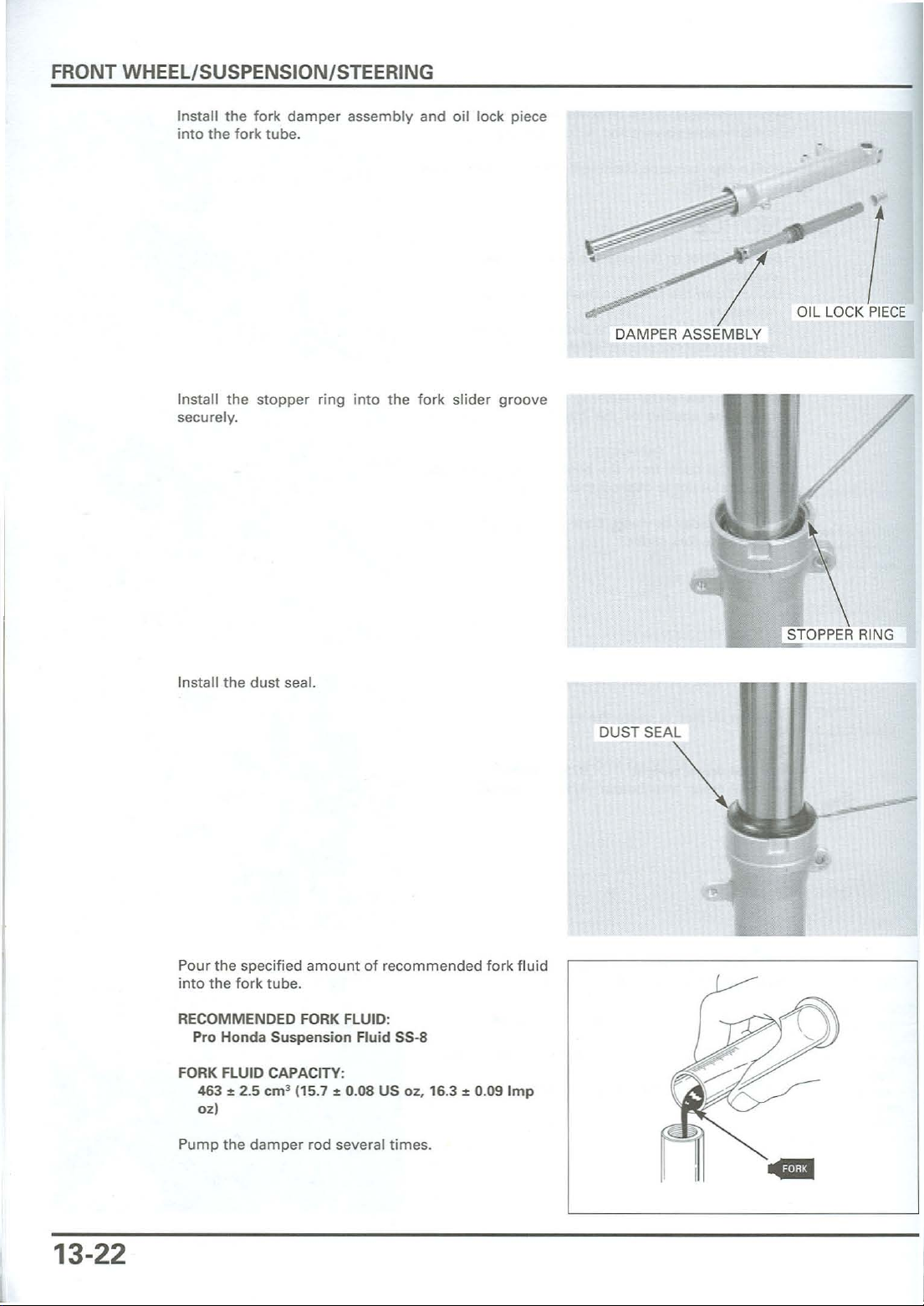
Install the fork damper assembly and oil lock piece
into the fork tube.
-
Install the stopper ring into the fork slider groove
securely.
Install the
dust
seal.
/"
DAMPER ASSEMBLY
DUST SEAL
_ _
OIL LOCK
....S..
TOPPER RING
/
PIECE
13-22
Pour the specified amount of recom
into the fork tube.
RECOMMENDED FORK FLUID:
Pro Honda Suspension Fluid
FORK FLUID CAPACITY:
e 2.5 em' 115.7
463
oz)
Pump the dampe r rod several times.
~
55-8
0.08 US oz, 16.3~0.09
men
ded fork fluid
-.
Imp
Page 6

FRONT WHEEL/SUSPENSION/STEERING
Be sure the oil
is the same
level
both
in
forks.
Measure
while
the
damper
FORK OIL LEVEL: 155 mm 16.1 in)
Pull
the tapered end facing
Screw the
the oil level
compressing
fork
tubeslowly
rod
more
the
damper
damper
from
the
tube
morethan5times
than10times
rod up
and
install
down
rod end
nut
the
all
.
the
fully
topofthe
way
.
the
forkspring
by hand.
after
fork
stroking
and the
tube
with
-
...
NUT
~
OIL
LEVEL
Insta ll
Install a
Apply
Hold
the
dampe
Hold the
ified
torque
the
spring
seat and
newO-ringonto
fork f
luid
to the
damper
r rod
fork
rod
unti
litseats on the
bolt and
.
the
new
and sc
tighten
spring
fork bolt.
O-ring.
rew
the lock
collar
the
fork bolt o
damper
.
rod lock nut.
nut
to the spec-
nto
FORK SPRING
SPRING COLLAR
<.
SPRING SEAT
the
TORQUE: 22 Nom 12.2
kgf
om. 16 Ibfoft)
13-23
Page 7
FRONT WHEEL/SUSPENSI
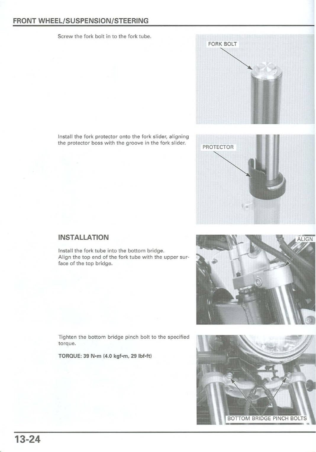
Screw the fork bolt in to the fork tube.
Install the fork protector onto the fork slider, aligning
the protector boss with the groove in the fork slider.
ON/
STEERING
FORK BOLT
-.
PROTECTOR
~
INSTALLATION
Install the
Align the top end of the for k tube with the upper sur-
face of the top
Tighten the
torque.
TORQUE: 39 N'm(4.0 kgf·m. 29 Ibf·ft)
fork
bottom
tube
into
thebottom
bridge
.
bridge pinch bolt to the specified
bridge.
•
13-24
Page 8
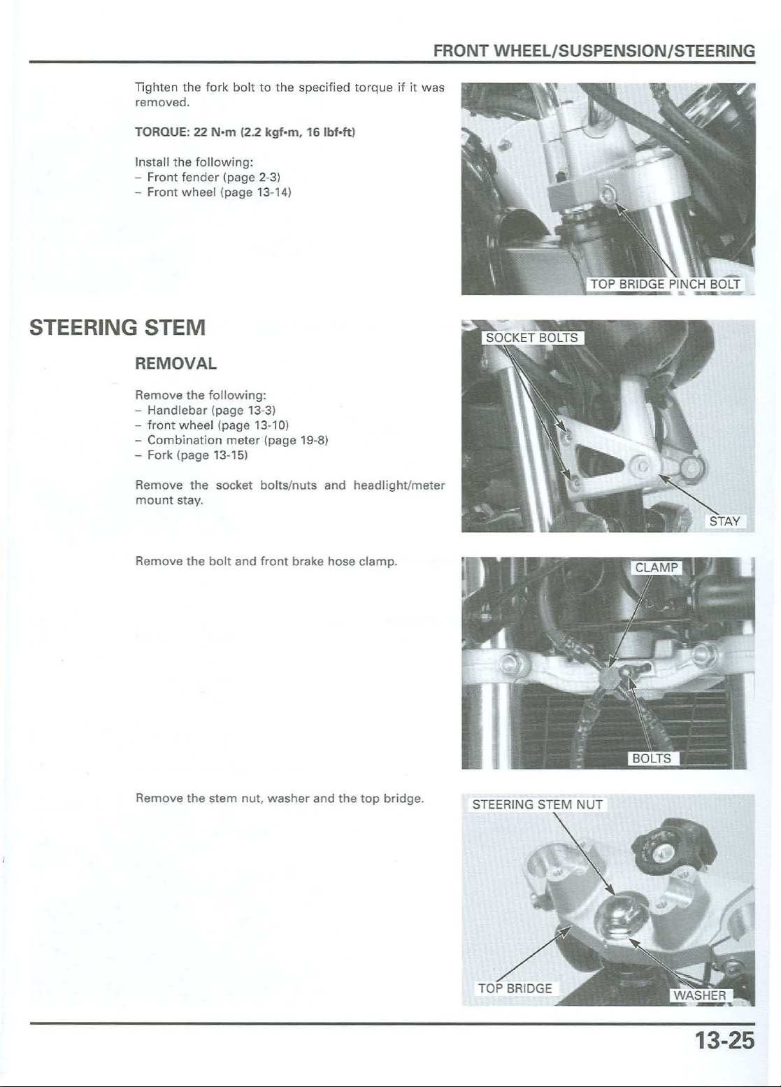
Tighten the fork bolt to the specified torque if it was
removed.
FRONT WHEEL/SUSPENSION/STEERING
TORQUE: 22
Install th e foll
ont
- Fr
- Front wheel (page 13-14)
fender (pag e 2-31
STEERING STEM
REMOVAL
Remove the followi ng:
- Handl ebar (page 13-3)
-
front
wheel
- Combin ation meter (page 19-8)
- Fork (page 13-151
Remove the socket bolts/nuts and headl ight/meter
mount stay.
N·m
(2.2
owing
:
(page 13-10)
kqf-m
, 16
Ibf·ftl
Remove the bolt and front brake hose clamp.
Remove the stem nut, washer and the top bridge.
STEERING STEM NUT
13-25
Page 9
FRONT WHEEL/SUSPENSION/STEERING
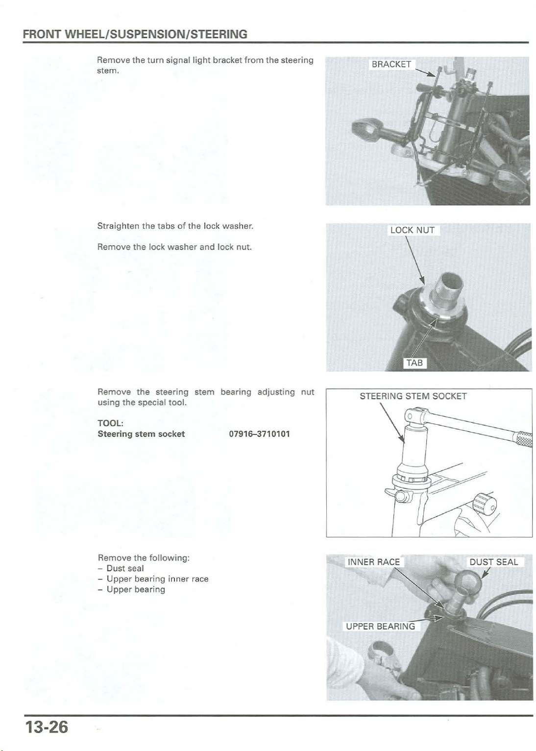
Remove the
stem.
Straighten the tabs of the lock
Remove the lock washer and lock nut.
turnsignal
light
bracket from the steering
washe
r.
LOCK NUT
\
Remove the steering stem bearing adjusting nut
using
the special
TOOL:
Steering
Remove th e
- Oust seal
-
- Upper bearing
Upp
er bearin g
stem
tool.
socket
followin
inner
07916-3710101
g:
race
STEERING STEM SOCKET
13-26
Page 10

FRONTWHEEL/SUSPENSI
ON/
STEERING
Note the installa -
tion direction
the
assembly
base.
Always replace
the bearing races
as a
set
- Steering stem
of
- Lo
wer
bearing
BEARING RACE REPLACEMENT
Replace
ciaI to ol.
TOOLS:
Ball race remover
Ball race remover set
- Remover
.
- Driver s
the
upp
attachment
haft
er bearing outer races
07953
07953
07946
07946
using
the
-4250002
-MJ10000
-MJ
10100
- M
J1020
0
spe-
or
~
,--
__
ATTACHMENT
DRIVER SHAFT
/
Replace the
cial
tool.
TOOLS:
Ball race remo ver
Ball race remover
Tempo
stemtoprevent
when
lower
rarily
removing
install
stem.
Removethe
equivalent
Remove
the
lower
tool,
dust
bearing
the
the
bearing
being
seal.
the
threads
lower
careful
outer
steering
frombeing
bear
ing
inner
nottodamage
races
using
07953
-3710500
07953-4250002
stem
nut
onto
damaged
inner
race f
race
with
a chisel or
the
the
rom
spe-
the
the
stem.
REMOVER
LOWER
INNER RACE
13-27
Page 11
FRONT WHEEL/SUSPENSION/STEERING
I"-
~
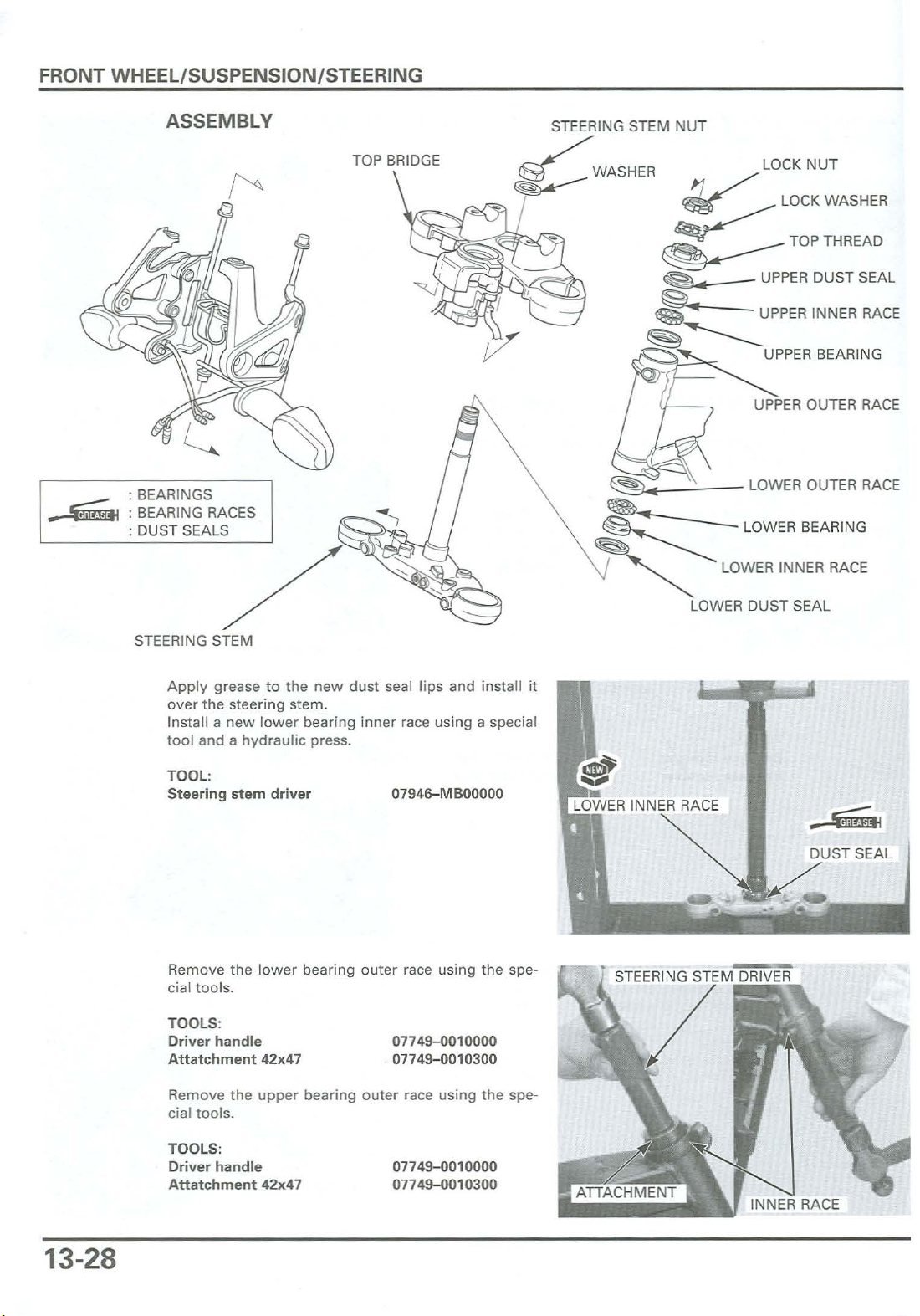
ASSEMBLY
: BEARINGS
: BEARING RACES
: DUST SEALS
TOP BRIDGE
STEERING STEM NUT
~WASHER
~
_
~
LOCK NUT
LOCK WASHER
~TOPTHREAD
~
• UPPER DUST SEAL
Jfi
. UPPER INNER RACE
UPPER BEARING
UPPER OUTER RACE
- LOWER BEARING
LOWER INNER RACE
~
~
~
~
~
------
• LOWER OUTER RACE
..
LOWER DUST SEAL
STEERING STEM
Apply grease to the
over the steering stem.
Install a new lower bearing inner race using a special
tool and a hydraulic press.
TOOL:
Steering stem driver 0794
Remove the lower bearing outer race using the spe-
cial tools.
TOOLS:
Driver handle
Attat
chment
Remove the upper bearing outer race using the spe-
cial tools.
42x47
new
dust seal lips and install it
6-M
BOOOOO
07749-0010000
07749-0010
DUST SEAL
300
13-28
TOOLS:
Driver handle
Attatchment
42x47
0
7749-0010000
07749-0010
300
INNER RACE
Page 12
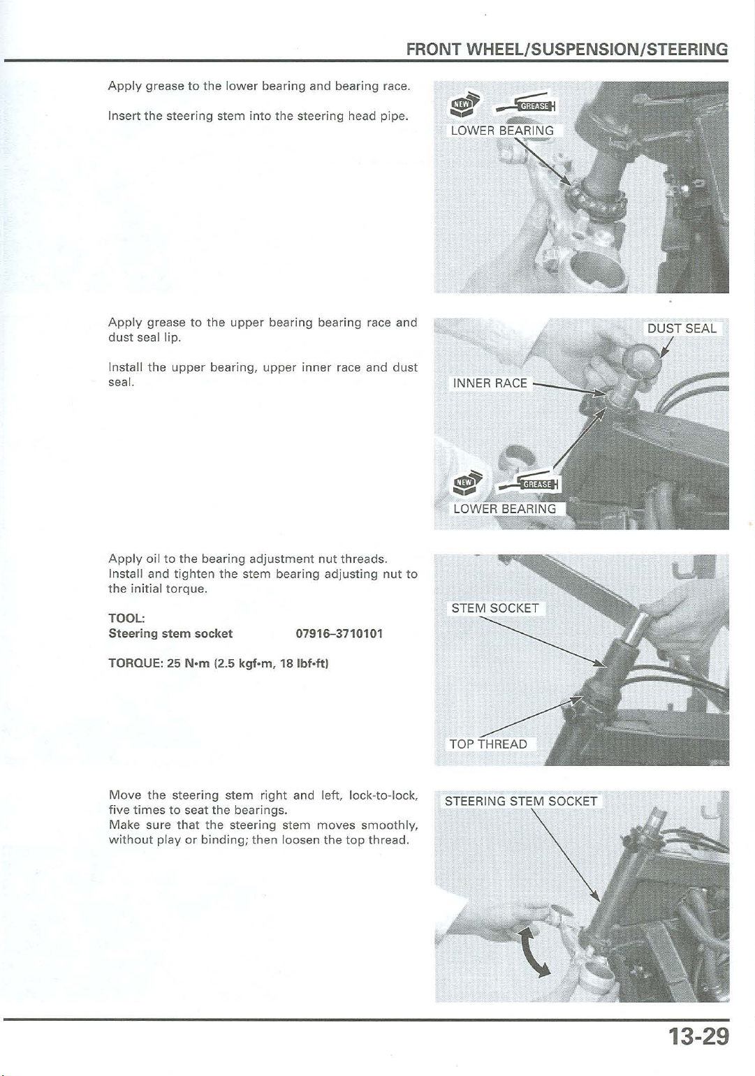
Apply
Insert
grease to the
the
steering stem
lower
bearing and bear
into
the steering head pipe.
ing
FRONT WHEEL/SUSPENSION/STEERING
race.
~
LOWER BEARING
..
-$iiiffi
~
Apply
grease to the
dust
seal lip .
Instal l the
seal.
Apply
oil to the bearing
Install and
the initial
upper
tighten
torque.
upper
bearing bearing race and
bearing,
the stem bearing
upper
adjustment
inner
nut
race and
threads.
adjust
ing
nut
dust
to
~
J
INNER RACE --_
I
--:c
TOOL:
Steering stem
TORQUE: 25
Move
the steering
fivetimes
Make sure
w
ithout
to seat the bearings .
that
play
soc
ket
N'm
(2.5 kqf-rn, 18
stem
the steering stem
or b
inding;then
07916-3710101
Ibf·ll)
right
and left, lock-to-lock,
moves
loosen the
smoothly,
top
thread.
STEERING STEM SOCKET
13-29
Page 13
FRONT WHEEL/SUSPENSION/STEERING
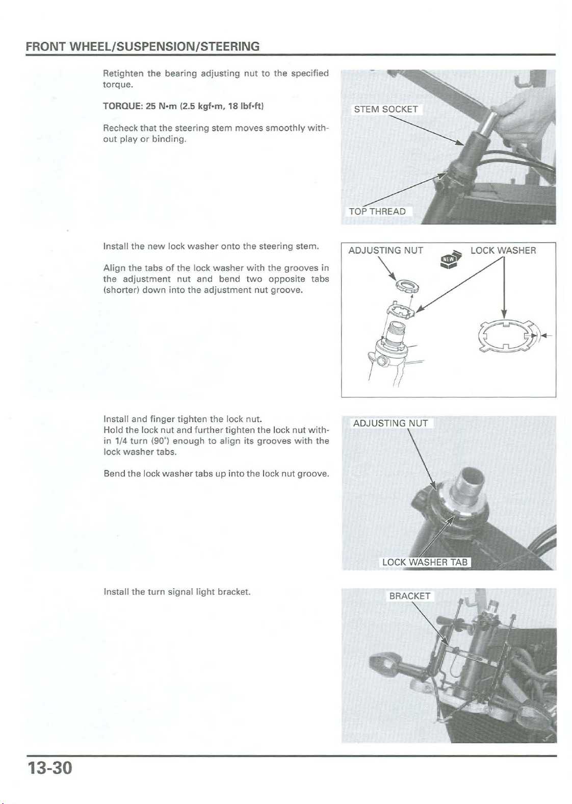
Retighten the bearing adjusting nut to the specified
torque.
TORQUE: 25 N·m12.5 kqf -m, 18 Ibf-ttl
Recheck that the stee ring stem
out play or binding.
Install the new lock washer onto the steering stem.
Align the tabs of the lock washer with the grooves in
the adju stment nut and bend two opposite tabs
(shorter) down into the adjustment nut groove.
Install and
Hold the lock nut and
in 1/4 turn (90·) enough to align its grooves w ith the
lock
washer
fing
er tighten the lock nut.
furt
tabs.
her
tig
moves
smoothly
hten the lock
with-
nutwith-
ADJUSTI NG NUT
~
~
e
~
LOCK WASHER
Bend the lock washer tabs up into the lock nut groove.
Install the turn signal light bracket.
BRACKET
13-30
Page 14
FRONT WHEEL/SUSPENSION/STEERING
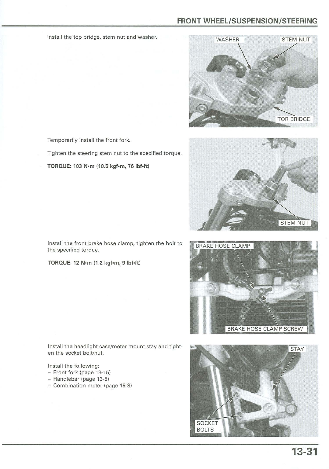
Install the top bridge, stem nut and washer.
Temporarily install the front fork.
Tighten the steering stem nut to the specified torque.
TORQUE: 103
N'm
(10.5
kqf-m,
761bf·1t)
WASHER STEM
..
NUT
Install the
the specified torque.
TORQUE: 12
Install the headlight case/meter mount stay and
en the socket bolt/nut.
Install the
- Front fo rk (page 13-15)
- Handlebar (page
-
Combination
front
brake hose clamp,
N'm
(1.2
following
:
13-51
meter
kgf.m,9Ibf·ltl
(page 19-8)
tighten
the
bolt
tiqht
to
-
13-31
Page 15
FRONT WHEEL/SUSPENSION/STEERING
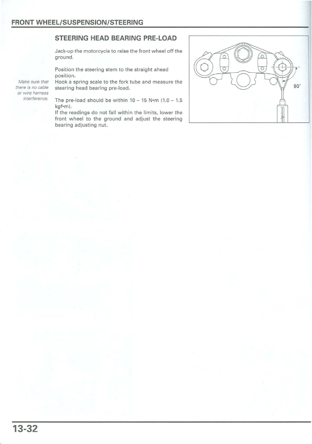
STEERING HEAD BEARING PRE-LOAD
Make sure that
no cable
there is
or wire harness
interference.
Jack-up
g
Positi on th e stee
posi
Hook
steering
The pre
kqf
If
front
bearing
the
motorcycle to raise th e
rou
nd.
ring
stemtothe
tion
.
a sp ring scaletothe fo rk tube and
head bearing pre
-load
-m ),
the
readingsdonot
wheel
adj
usting
shouldbewithin
to the
nut.
gro
-load
fall
und
front
w heel offthe
straig
ht ahead
measure
,
10 - 15 Nom (1.0 - 1.5
withinthe
and
limits.
adjust
the
lower
stee
the
the
ring
13-32
Page 16
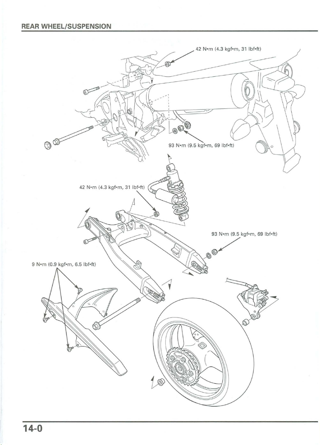
REAR WHEEL/SUSPENSION
____
-<::-~
~
42 Nom (4.3 kqf-m, 31 IbfO"ft).-
...-fYCI
9 Nom (0.9 kgfom, 6.5 lbf-ft)
93 Nom (9.5 kqf-rn , 69 lbf-ft)
~
/
14-0
Page 17
14.
REAR
WHEEL/SUSPENSION
SERVICE INFORMATION
TROUBLESHOOTING
REAR WHEEL
14-1
14-2
14-3
SHOCK ABSORBER
SWINGARM
SERVICE INFORMATION
GENERAL
A contaminated brake disc or pad reduces s
withahigh
After
The shock
Before disposalofthe shock abso rber, release the nit
When
Use only tires marked "TUBELESS·and tubeless valves on rims marked "TUBELESS TIRE APPLICABLE:'
Use
genu
Refer to section 15
quality
the rear wheel insta llat
abso
servicing the rear
ine Honda replaceme nt
brake degreasing a
rber contains nitrogen
whee
for
brake sys
ion
. check
l and suspens
bolts
tem
information.
topp
gent
.
the
brake o
und
er high pres
ion,support
and
nuts
ing power. Discard con
perationbyapplying
sur
roge
for
all suspens
e. Do not a
n (page 14-13).
the
motorcycle
ion
llow
pivot
tam
inated pads and clean a contaminated disc
the brake pedal.
fire or heat near
usingasafety
and
mount
stand or
ingpoint
the
shockabso
hoist
.
14
-10
14-14
rber.
.
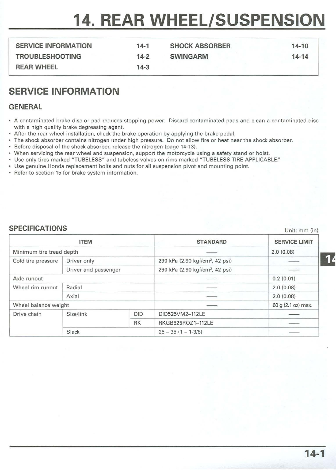
SPECIFICATIONS
Minimum
Cold tire pressure Driver
Axlerunout
Wheelrim
Wh
Drive c
tir
e tread depth
runout
eel balanceweight
hain
Dr
Radial
Axial
Sizellink DID DID525VM2-112LE
Slack 25 - 35 (1 - 1-3/8)
Unit:mm
ITEM STANDARD SERVICE LIMIT
only
iver
and passenge r
--
290 kPa (2.90 kgf/em' , 42 psi)
290 kPa (2.90 kgf/em', 42 psi)
--
- -
--
--
2.0 (0.08)
--
--
0.2 (0.01)
2.0 (0.08)
2.0 (0.08)
50g (2.1oz)max.
--
RK
RKGB525R
Ol
1-112LE
--
--
(in)
14-1
Page 18
REAR WHEEL/SUSPENSI
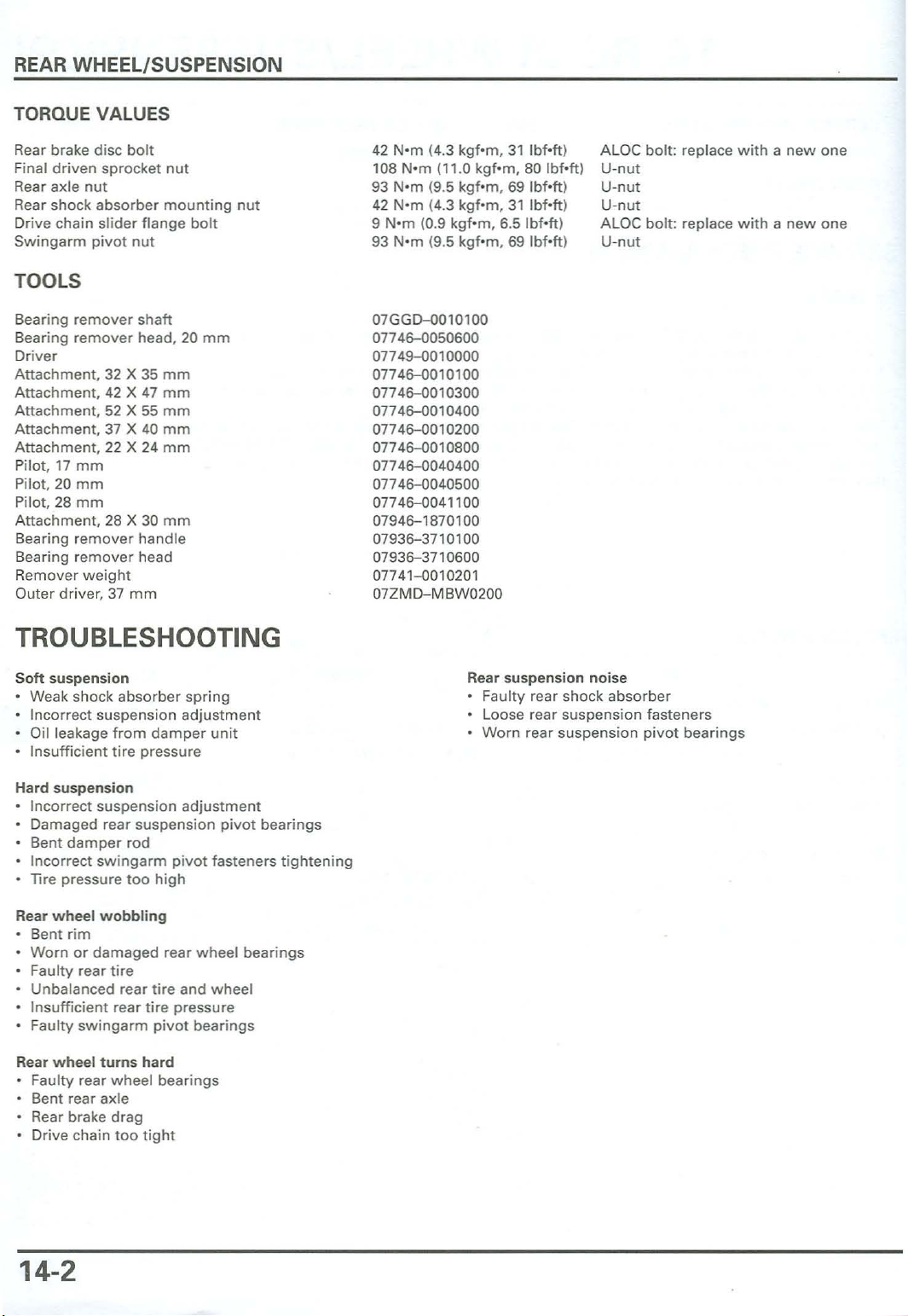
TORQUEVALUES
ON
Rear brake disc
Final driven sprocket nut
Rear axle nut
Rear shock absorber mounting nut
Drive chain slider flange bolt
Swingarm pivot nut
bolt
TOOLS
Bearing
Bearing remover head, 20
Driver
Attachment, 32 X 35
Attachment, 42 X 47
Attachment
Attachment, 37 X 40
Attachment,
Pilot. 17
Pilot, 20
Pilot, 28
Attachment,
Bearing remover hand le
Bearing remover head
Remover we ight
Outer driver, 37
TROUBLESHOOTI
remov
, 52 X 55
22 X 24
mm
mm
mm
28 X 30
er shaft
mm
mm
mm
mm
mm
mm
mm
mm
NG
42 Nom (4.3 kqf-rn, 31 lbf-ft}
108 Nom (11.0 kqf-rn, 80 lbf-tt)
93 Nom (9.5 kg10m, 69 lbf-ft )
42 Nom (4.3 kglom, 31
kqf
9 Nom (0.9
93 Nom (9.5 kqf-rn , 69
07GGD-0010100
0774EHl050600
07749-0010000
0
774EHlOl0l00
0774EHlO10300
0774EHlOl0400
0774EHlOl0 200
0774EHlOl0800
0774EHl040400
0774EHl040500
0774EHl041100
07
94607936-3710100
07936-371060 0
07741-0010201
D-M
07ZM
-rn, 6.5 lbf-ft)
1870100
BW0200
Ibl
lbf
olt)
-ft)
Al
o e bolt: replace
U-nut
If-nut
U-nut
AlO
e bolt: replace with a
If-n ut
withanew
new
one
one
Soft
suspension
Weak shock abso rber
Incorrect suspension adjustment
Oil leakage from
Insufficient tire pressure
Hard suspension
Incorrect suspension adjustment
Damaged rear suspension pivot bearings
Bent
damper
Incorrect swingarm pivot fasteners tightening
Tire pressure too high
Rear w heel
Bent rim
Wornordamaged
Faulty rear tire
Unbalanced rear tire and
Insufficient rear tire pressure
Faulty swingarm pivot bearings
Rear
whee
Faulty rear w hee l bearings
Bent rear axle
Rear brake drag
Drive chain too tight
rod
wobbl
l turns hard
damper
ing
rear
spring
unit
wheel
wheel
bearings
Rear suspension noise
Faulty rear shock absorber
loose
rear suspension fasteners
Worn rear suspension pivot bearings
14-2
Page 19
REAR WH EEL
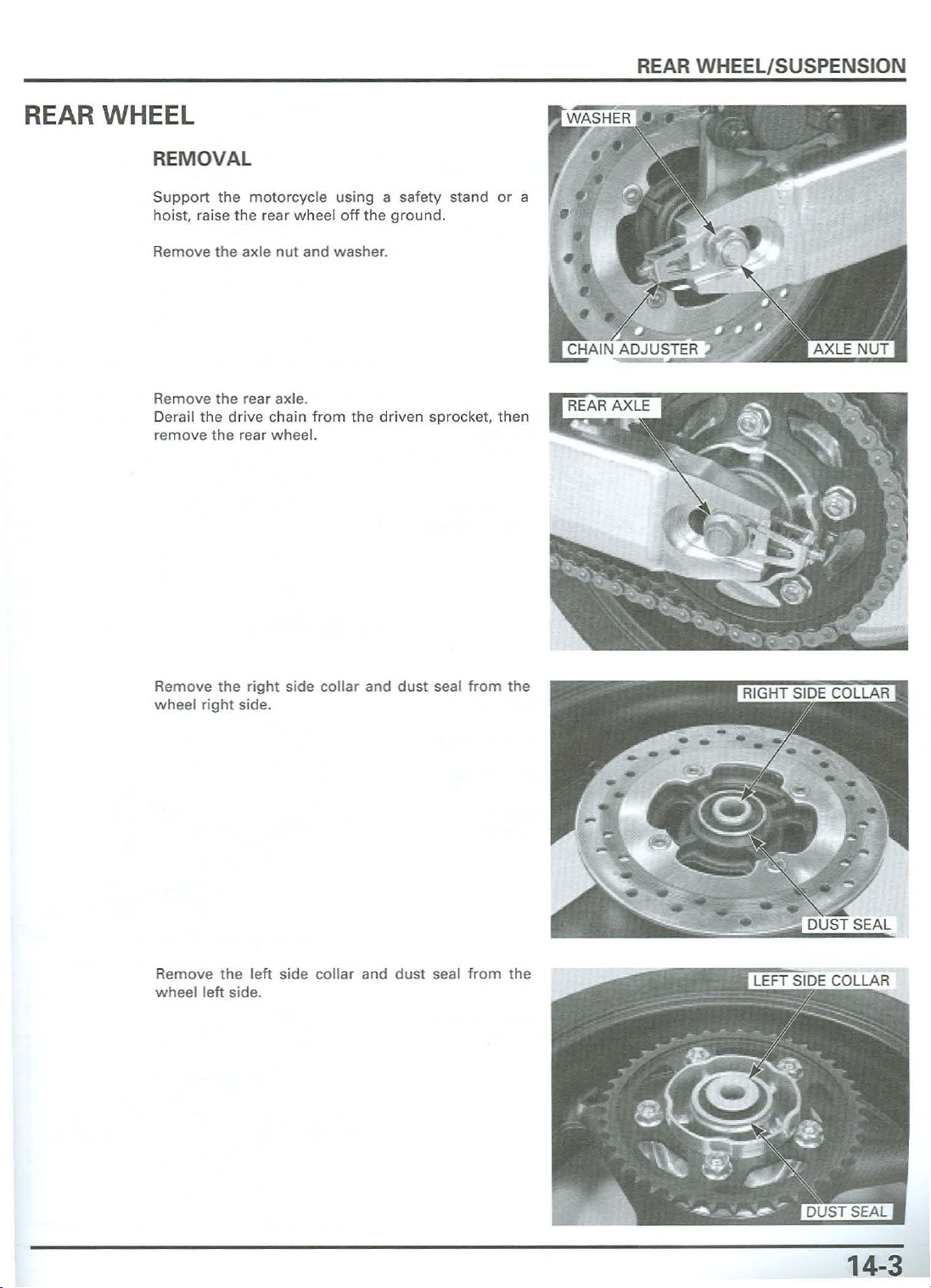
REM
Supp
hoist, raise the rear
OVAL
ort
themotorcycle using a safety stand or a
whe
el off the ground.
REAR WHE
EL/
SUSPENSION
Remove
Remove
Derail thedrive chain
remove the rear w heel.
Remove the right side collar and
wheelright
the
the
axle
nut
rear axle .
side.
and
washe
from
thedriven sprocket,
r.
then
dust
seal
from
the
Remove the
wheel left side.
left
side collar and dust seal f
rom
the
14-3
Page 20
REAR WHEEL/SUSPENSION
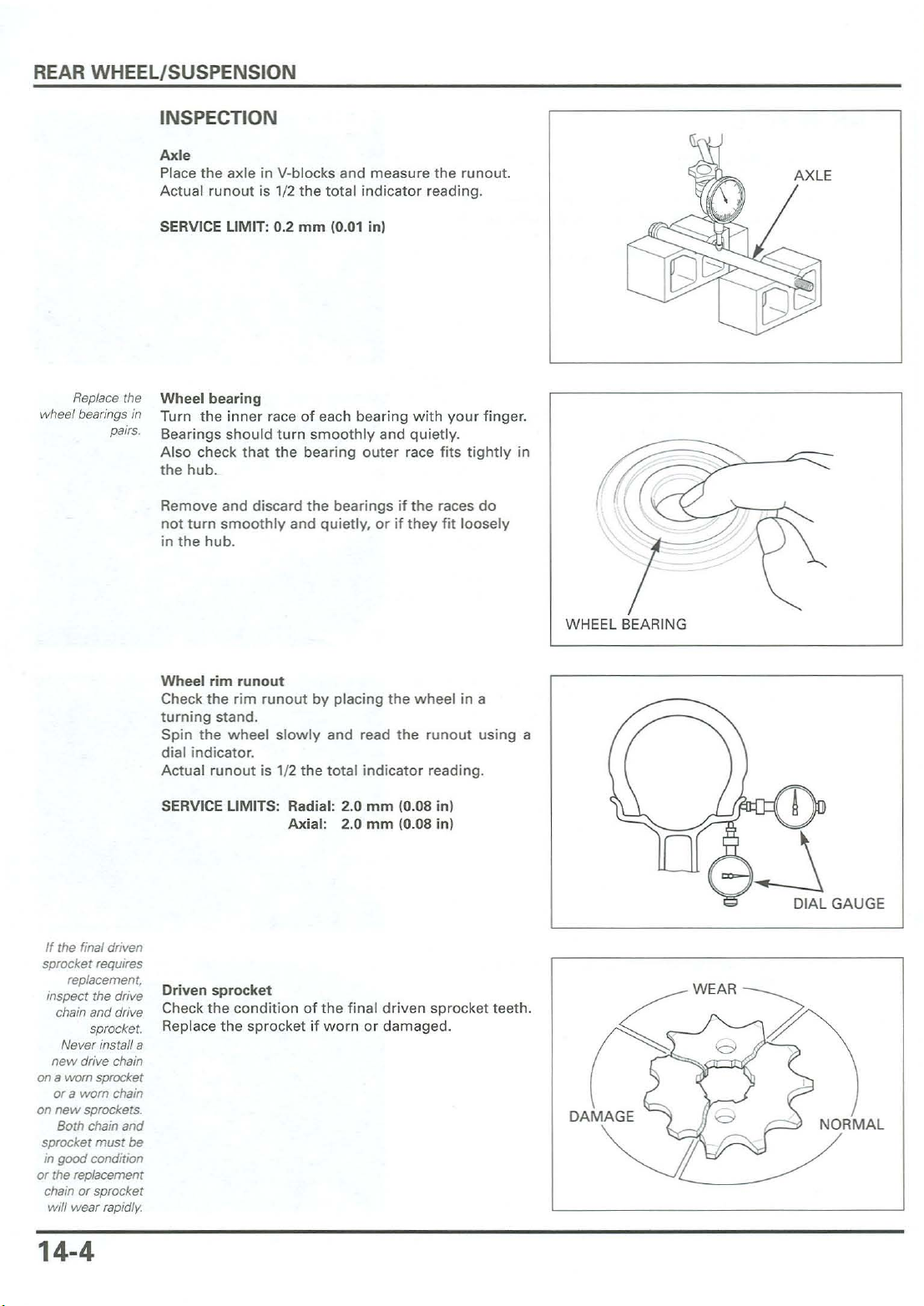
INSPECTION
Axle
Place the axle in V-blocks and measure the
Act
ual run out is 1/2 the
tota
l indicatorreading.
runo
ut.
Replace the
wheel bearings
pairs.
SERVICE LIMIT: 0.2
Wheel
in
bearing
Turn
the
inn
Be
arings
should turn smoo
Also check t hat
the hu b.
Remove and discard the bearings
not
turn smooth ly and quiet ly, or if they fit
in the
hub
.
Wheelrim
Check
turn ing stand.
Spin
dial indica
Actual runout is 1/2 the total indicator reading.
runout
the
rimrunout
the
w heel slowly and read the run out using a
tor
mm
10.01
in)
er raceofeach bearing
thl
y and qu
the
bearing oute r race
by pla cing th e wheel in a
.
if the races do
withyour
ietly
.
fit
s t i
loosely
finger
ghtl
.
y in
WHEEL BEARING
the final driven
If
sprocket requires
replacement
inspect the drive
chain and drive
sprocket.
N
ever
install a
new
driv
ona
on
sprocket
in
or the replacement
chain
will
e chain
Il\Iom
sprocket
or a worn chain
new
sprockets.
Both
chain
and
must
good
orsprocket
wearrapidly.
be
condition
14-4
SERVICE LIMITS: Radial: 2.0
Axial: 2.0
Driven
Check
sprocket
the
con
ditionof
Replace the sprocket
the final d
if
wornordamage
mm
10.08in )
mm
10.08 in)
riv
en sprocket teeth.
DIAL GAUGE
d.
(i
DAM
~R
W
'
:~
M
AL
Page 21

DISASSEMBLY
REAR WHEEL/SUSPE NSION
If you will be
disassembling the
driven flange.
loosen the driven
sprocket nuts
before removing
the driven flange
from the
wheel
hub.
Remove
Remove
wheel
hub
the
bolts
the
drivenflange
.
and brake disc.
assemblyfrom
the
left
Remove the
Remove
Driven
Loosen the
Remove the driven flange f
r
emove
Remove the
the
flange
the
wheel
Ocrinq.
bearing
driven
driven
driven
damper
removal
sprocket nuts.
sprocket
flange
rubbers
bearing and colla r.
.
rom
the w heel hub, then
nuts
and sprocket.
14
-5
Page 22
REAR WHEEL/SUSPENSION
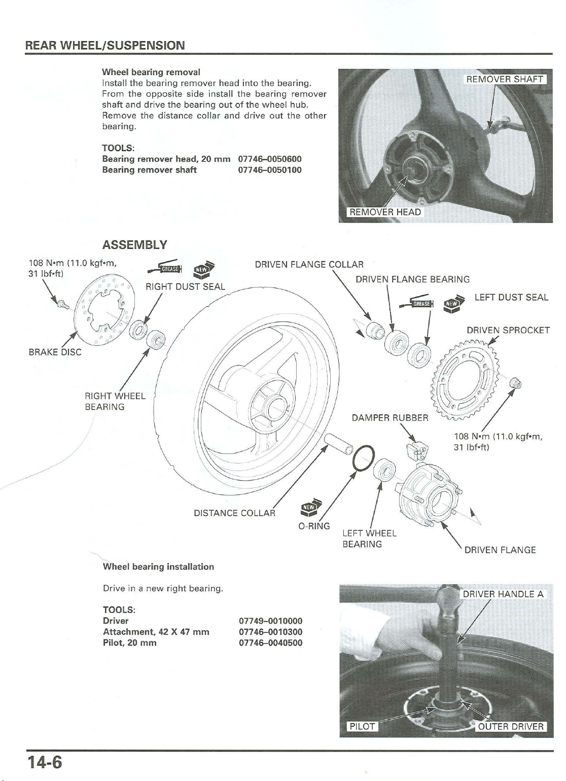
Wheel bearing removal
Install the bearing remover head into the bearing.
From the opposite side install the bearing remover
shaft and drive the bearing out of the wheel hub.
Remove the distance collar and drive out the other
bearing .
TOOLS:
Bearing remover head, 20
Bearing
remover
shaft
ASSEMBLY
108 Nom (11.0 kqf-rn.
31 Ibfoftl
-,
mm
07746-0050600
07746-0050100
DRIVEN SPROCKET
BRAKE DISC
DISTANCE COLLAR
Wheel bearing installation
Drive in a new right bearing .
TOOLS:
Driver
Attachment,
Pilot,20mm
42 X 47
mm
07749-0010000
07746-0010300
07746-0040500
~
S
O-RING
LEFT WHEEL
BEARING
DRIVEN FLANGE
14-6
Page 23
REAR WHEEL/SUSPENSION
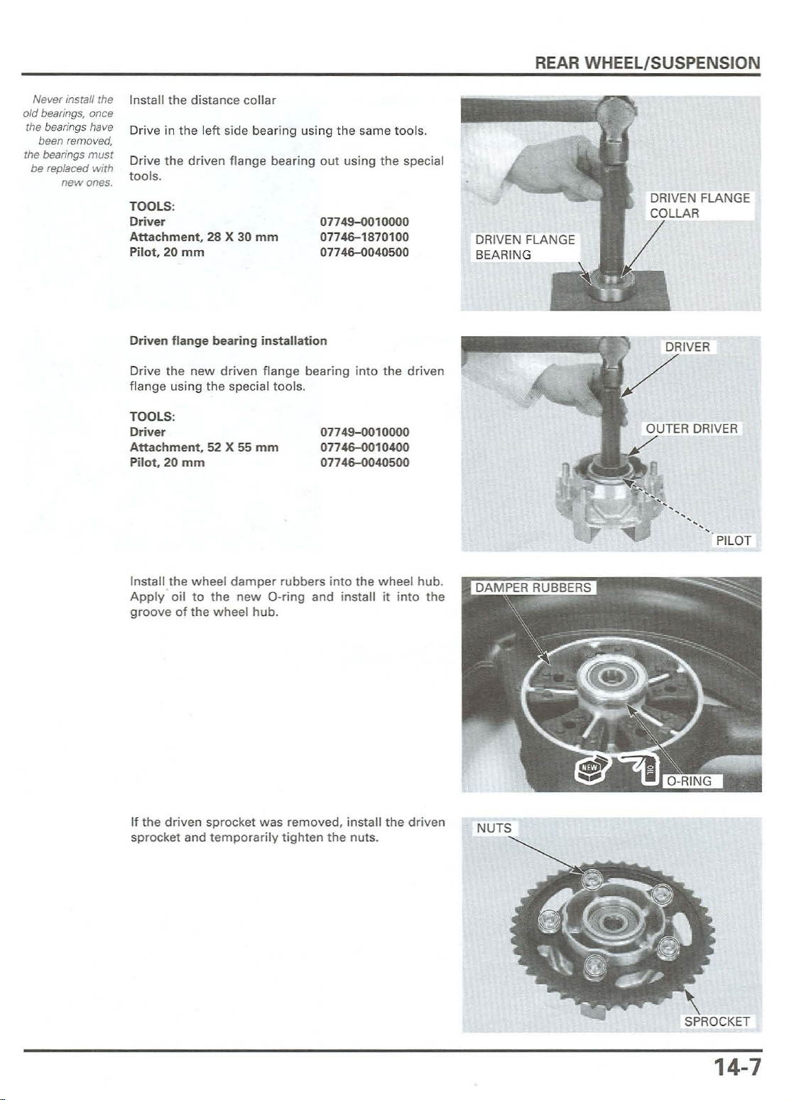
Never install the
old bearings, once
the bearings have
been removed,
the bearings
be replaced
must
with
newones.
Install
the
Driv
dista nce
e in t he l
eft
side
colla
bear
r
ing using
the
same
too
ls.
Drive the driven flange bearing out using the special
too
ls.
TOOLS:
Driver
Attachment. 28 X 30 mm
Pilot, 20
Driven flangebearing
Drive t he
flange using th e spec ial
TOOLS:
Driver
mm
new
installat
driven flange
Attachmen1.52 X 55 mm
Pilot . 20
mm
too
0774~010000
07746-1870100
07746-0040500
ion
bearinginto
ls.
0774~010000
07746-0010400
07746-0040500
the
driven
OUTER DRIVER
the
Install
Apply
wheel
'
oil
to the
groove of the
If
the
driven
sprocket
and
damper
new
whee
l hub.
sprocket
temporarily
rubbe
rs into
the
O-ring and install it
wasremoved,
tighten
the
insta
nuts
wheel
ll the
.
into
driven
hub
the
PILOT
.
SPROCKET
14
-7
Page 24

REAR WHE
EL/
SUSPENSION
Install the d
wheel
TORQUE: 108
Install the brake
facing
Install and
to
rque.
TORQUE: 42 N·m
hub
out
riven
.
N'
.
tig
flange
assembly
m 111.0kgf·m. 80 Ibf·ft)
disc
with
its
hten the
14.
3 k
new
gf.m.
into the left
rotating
boltstothe
31 Ibf·ft)
direction
specified
mark
WHEEL BALANCE
The
wheel
remounted
For
optimum
dot
on the s
stem
. Rem ount the
Note
the
tire .
balance
.
ide
rotatingdirection
must
balance, the
wall)
must
tire
be checked w hen the tire is
tire
balance
be located
if necessary.
marks on
mark(apaint
nexttothe
the
wheel
valve
and
BALANCE
MARK
14-8
ROTATING DIRECTION MARKS
Page 25

Mount
the
wheel,tire
inspection stand.
Spin
the
wheel,
est(heaviest)
Do
this
twoorthree
the
wheel
If
the
same
To balance
l
ightest
Add
stopinthe
Do
sideofrim,
just
not
add
enough
allow
partofthe
is balanced, it
position
the
same
more
wheel,
.
weightsothe
posit
than
INSTALLATION
Apply
right
grease and
side.
install
and
brake disc
it to stop, and
wheel
w ith chalk.
timestoverify
will
not
install
balance
the
side
opposite
wheel
ion
when
it is
60 9 (2.1 oz)tothe
the
new
assembly
mark
the
heaviest
stop
consistently
weightsonthe
the chalk marks.
willnolonger
spun.
rear
dust
seal to
the
wheel.
the
REAR WHEEL/SUSPENSION
on an
low-
area.
in
Apply
grease and
install
the
dust
seal to
the
left
side.
/
Apply
grease to the side collars inside and grooves.
Install
the
side
collars
.
14-9
Page 26

REAR
WHEEL/SUSPENSION
Install the rear brake caliper bracket onto the guide of
the swingarm.
Be careful
damage the brake
not
pads.
to
Place the rear wheel into the swingarm.
Install the drive chain over the driven sprocket.
Install the rear axle from the left side.
Install the washer and axle nut.
Adjust
thedrive chain slack (page 3-10).
Tighten the axle nut to the specified torque .
TORQU E: 93
N'm
(9.5 kq
f-m,69lb
f-ft]
SHOCK ABSORBER
REMOVAL
Remove
Remove the side cover (page 2-2).
Secure the motorcycle using a hoist or an equivalent.
Loosen the shock absorber reservoir band screw and
remove the reservoir from the inner fender.
the
seat (page 2-21.
14-10
BAND
SCREW
Page 27
REAR
WHEEL/
SUSPENSION
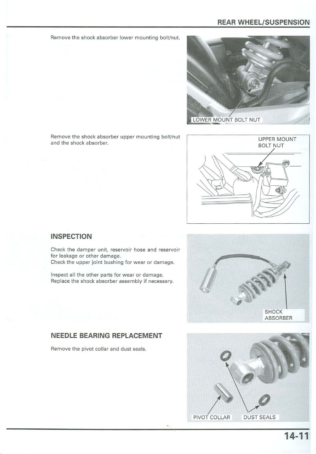
Remove the shock abso rber
Remove the shock
and
the
shock absorber.
absorber
lower
mou
nting
uppermounting
bolt/nut.
bol
t/nut
UPPER
BOLT NUT
MOUN
T
INSPECTION
Check the
for
Check the
Inspect all the
Replace the shock
NEEDLE BEARING REPLACEMENT
Remove the
damper
leakage or
upper
unit, reservoir hose and reservoir
other
other
pivot
damage
joint
parts
absorber
collar
.
bushing
for
wearordamage
for
wear
or damage.
assembly if necessary.
and
dust
seals.
.
r
\
/
SHOCK
ABSORBER
(J
SEALS
o
I
PIVOT COLLAR
"
DUST
14
-11
Page 28
REAR
WHEEL/SUSPE NSION
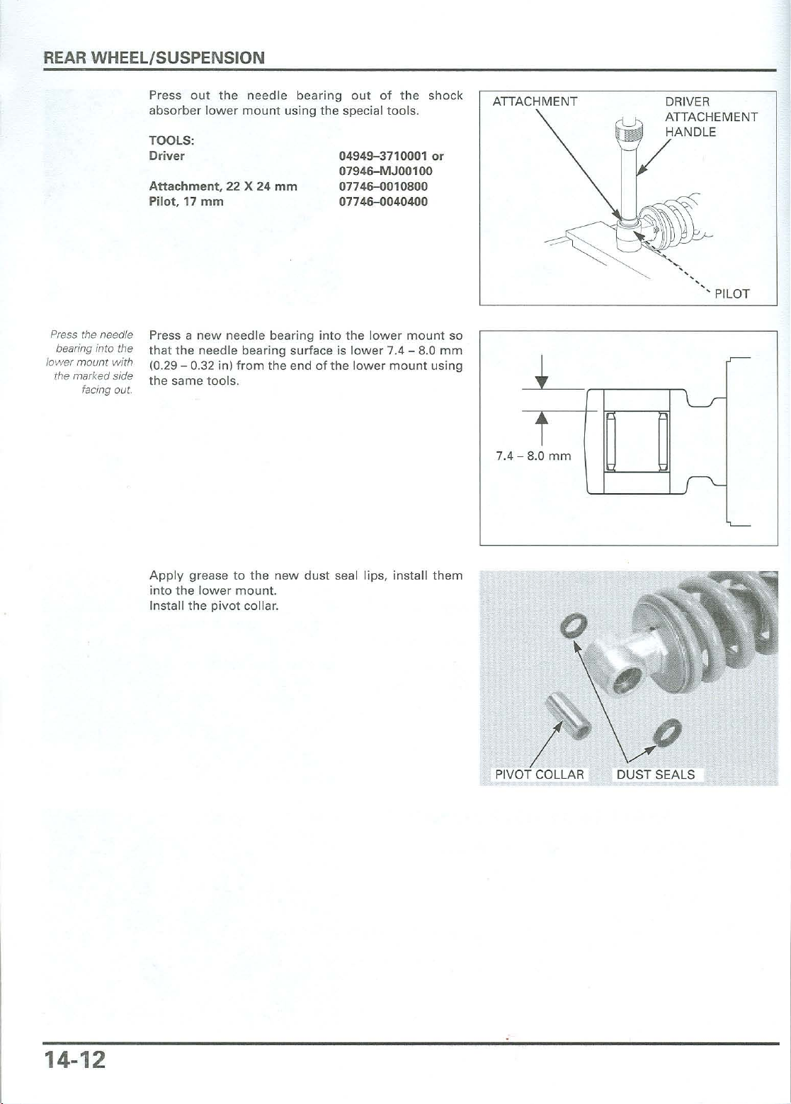
Press the needle
bearing into the
lower mount with
the marked side
facing out.
Press out the
absorber
TOOLS:
Driver
Atta
chment, 22 X 24 mm
Pilot, 17
Press a new needle bearing into the lower
that the needle bearing surface is lower 7.4 - 8.0
10.29- 0.32 in)
the s
mm
ame
needle
lower
mount using the special tools .
from
tools.
bearing out of the shock
the
endofthe
04949-3710001 or
0794
6-MJ00100
07746-00
07746-0040400
lower
10800
mount
mount
so
mm
using
ATTACHM ENT DRIVER
ATTACHEMENT
HANDL
,
...........
7.4 - 8.0
mm
E
PILOT
Apply grease to the
into the lower
Install
the
pivot
mount
collar
new
dust seal lips, install
.
.
them
o
/ D
DUST SEALS
14-12
Page 29
SHOCK ABSORBER DISPOSAL
PROCEDURE
REAR WHEEL/SUSPENSION
Remove the da
Release the nitrogen
the valve
I
NOTICE
Po
int
g
ett
ing in your eyes.
Before
core
.
mperreservo
from
ir cap.
the res
ervoir
I
the
valveaway
dispo
salofthe shock absorber, release th e
fro m you to
by depressing
pre
vent
nitrogenbypressing the valve core. Then remove
the
valvefrom
the shock
absorber
res
ervoir
.
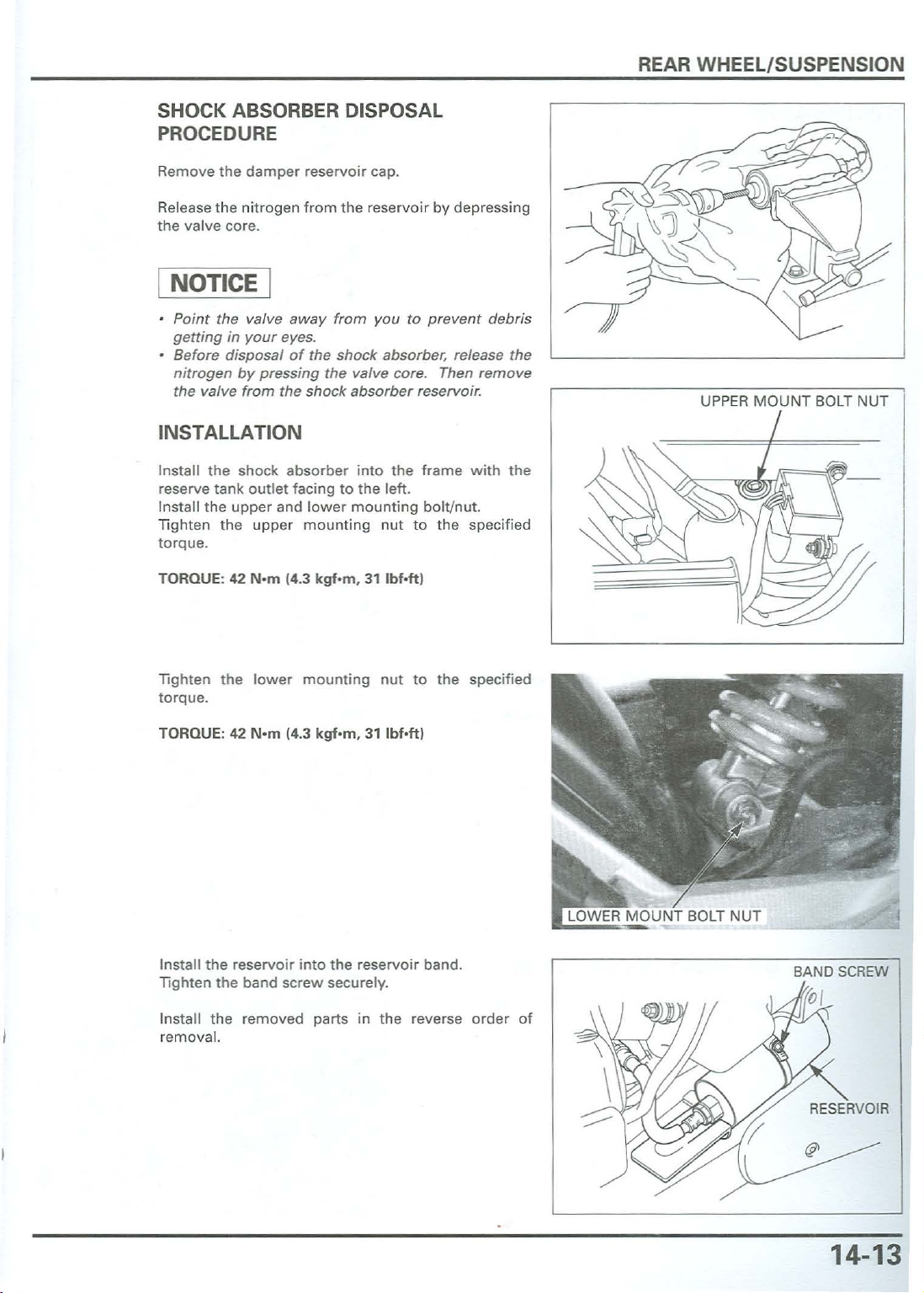
INSTALLATION
Install
the
shock absorbe r int o
reserve tan k
Install the upper and
Ti
ght
en the upper
torqu
e.
TORQUE: 42
outlet
N'm
14.3
facing to the left.
lowermounting
mount
kqf-m,
ing
nut
31
the
frame with
bolt/n ut.
to the spe
Ibf
·ftl
debris
the
cified
UPPER
MOUNT
BOLT NUT
Tighten the low er
mountingnut
to
the specifi ed
to rque.
TORQUE: 42 Nsm 14.3
Insta ll
the
rese
rvo
ten the
Tigh
Install the removed parts in the reverse order of
removal.
band screwsecur
kgf'm,
31
lbf-ft}
ir intothe reservoir band.
ely
.
BAND SCREW
14-13
Page 30
REAR WHEEL/SUSPENSION
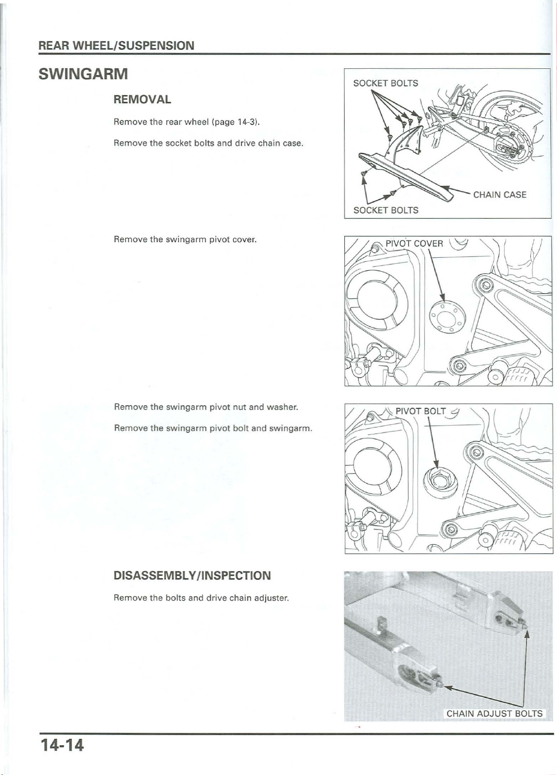
SWINGARM
REMOVAL
Remove the rear wh eel (page 14-31.
Remove the socket bolts and drive chain case.
Remove the swingarm pivot cover.
CHAIN CASE
SOCKET BOLTS
Remove the swingarm pivot nut and was her.
Remove the swingarm pivot bolt and swingarm.
DISASSEMBLY/ INSPECTION
Remove the bolts and drive chain adjuster.
14-14
~
CHAIN
ADJUST
BOLTS
Page 31

REAR WHEEL/SUSPENSION
Remove the
Check the
Remove
swinga
Check
fatigue .
the
rm left
the
bolts
drive
dust
chain
pivot
pivot
seals and
and
.
drive
slider
collar
chain slider.
for
wearordamage
and
dust
collars
seals
for
from
damage
CHAIN SLIDER -
.
the
or
-~
DUST SEALS ·
BOLT
o
p
Turn
the
inner raceofright
finger
that
.
smoothly
.
the
should
bearing
and
quietly,orifthey
your
The bearings
check
hub
Remove and discard the bearings if the races do
turn
pivot.
turn
pivot
smooth
outer
bearings w ith
ly and quietly. Also
race
fits
tightlyinthe
fit
looselyinthe
not
SIDE COLLARS
\
DISTANCE COLLAR
14
-15
Page 32

REAR WHEEL/SUSPENSION
P
IVOT
BEARING REPLACE
MENT
LEFT
PI
DISTANCE
COLLAR
DUST SEAL
(28x 37 x 41
VOT NEEDLE BEARING
~~;;:;:;;;:;:;iiC
Remove the snap ring.
=if
!-
DUST SEAL
-
(28x 37 x 4)
SIDE COLLAR
DUST SEAL
(27 x 34 x 4)
RIGHT PIVOT BEARING (20
x 37 x 91
DUST SEAL
(28x 37 x 4)
SNAP RING
14-16
Remove the right pivot radial ball bearing using the
special tools .
TOOLS:
Bearing remover handle
Bearing remover shaft set, 20mm
Removerweight
07936-3710100
07936-3710600
07741-ll010201
Page 33

REAR
WHEEL/SUSPENSION
Press the
cial
tools
and a hydraulic press.
TOOLS:
Driver
Attachment
Pi
lot
, 28
mm
ASSEMBLY
NEEDLE BEARING
left
pivot
, 32 X 35
DUST SEAL
needle
mm
COLLAR
bear
ing
out using the spe-
07949-3710001
07746-001000
07746-0041
BALL BEARINGS
1
100
COLLAR DUST SEAL
l'
~~""
""
SWING ARM
DRIVER
OUTER
DRIVER
PILOT
ousr
CHAIN SUDER
Press the needle
bearing into the
pivot
with
marked side
the
facing out.
ssxt,
~
\a:
~
Pack
Press
until
press.
TOOLS:
Driver
Attachment.37mm
Pilot, 28
COLLAR
the
new
the
needle
it seats using
mm
BOLTS
need le bearing w ith grease.
bea
ring
the
into th e
specia l
swingar
tools
andahydra
07749-0010000
07ZMD-MBW0200
07746-0041100
,/
CHAIN ADJUSTER
m left pivot
ulic
OUTER
DRIVER
14-17
Page 34

REAR WHEEL/SUSPENSION
Press the radial ball bearing in using the special too ls
and a hydraulic press.
TOOLS:
Driver
Attac
hment
, 32 X 35
P
ilot,20mm
Install the snap ring into the groove securely.
mm
0774~010000
0774lHlOl0l00
0774lHl040500
OUT
ER
DRIVER
PILOT
Apply
grease to the
seals into the left swingarm pivot.
Fill the grease up between the inner dust seal and
need le bearing.
Install the pivot distance colla r.
Apply grease to the dust seal lips, then install the dust
seals and pivot collar into the right swingarm pivot.
Install the bolts and drive chain adjusters.
dust
seal lips,
then
install the
dust
SIDE COLLARS
p
DISTANCE COLLAR
"
14-18
Page 35

REAR WHEEL/SU SPENSION
Install t he
boss on
Install the
swingarm
Install and t
ing
TORQUE: 9 Nsm (0.9
drive
the
swingarm
drive
.
igh
boltstothe
chain
chain
ten
specified
the
slider
.
slider
new
torque
kqf-rn,
, a
lign
ing
bosses into
drive
chain s
6.5 Ib
f.f
tl
theslitwith
the
hole
lider
mount-
the
in the
~~
;trZBOLT
INSTALLATION
Apply
a
thin
coatofgrease to theswingarm
slid
ing
surface.
Insta ll
the
swingarmonto
Install
theswi
swingarm
Install and
ified
to rque.
TORQU E: 93
Install
the
pivot.
tighten
N'm
pivot
ngarm
theswinga rm
(9.5
bolt
the
frame.
pivot
bolt
kqf-m,69Ibf.ftl
collar
.
to
pivot
pivot
the
frame
nuttothe
bolt
and
spec-
14-19
Page 36

REAR WHEEL/SUSPENSION
Install the socket bolts and drive chain case.
Install th e rear w heel (page 14-9),
CHAIN CASE
SOCKET BOLTS
14-20
Page 37

HYDRAULIC BRAKE
FRO
NT:
15-0
(3 1 kqf-m, 22 lbf-ft)30 Nom .
Page 38

15. HYDRAULIC BRAKE
SERVICE INFORMATION
TROUBLESHOOTING
BRAKE
AIR BLEEDING
BRAKE PAD/DISC
REAR:
flUID
REPLACEMENT/
15-2
15-3
15-4
15-7
FRONT MASTER CYLINDER
REAR MASTER CYLINDER
FRONT BRAKE CALIPER
REAR BRAKE CALIPER
BRAKE PEDAL
10 Nem (1.0 kqf-rn, 7
lbf
15-10
15-15
15-19
15-23
15-26
-ft)
10 N-m (1.0 kqf-rn, 7 lbf-ft l
~
? o.s kqf-rn,
c-:
.f . .
"'"'"'"
15-1
Page 39

HYDRAULIC BRAKE
SERVICE INFORMATION
GENERAL
A
CAUTION
Frequent inhalation of brake pad dust, regardless of material composition could be hazardous to your health.
Avoid breathing dust particles.
• Never use an air hose or brush to clean brake assemblies. Use an OSHA-approved vacuum cleaner.
A contaminated brake disc or pad reduces stopping power. Discard contaminated pads and clean a contam inated discwith
a high quality brake digreasing agent.
Check the brake syste m by appl ying
Spilled brake fluid w ill severely damage instrument lenses and painted surfaces. It is also harmful to some rubber parts. Be
careful whenever you remove the reservoir cap; make sure the front reservoir is horizontal first.
Never allow contaminates (dirt, water,
Once the hydraulic system has been opened, or if the brake feels spongy, the system must be bled.
Always use fresh DOT
as they may not be compatible .
Always check brake operation before riding the moto rcycle.
4 brake fluid from a sealed container when servicing the system. Do not mix different types of fluid
the
brake lever or pedal after the air bleeding .
etc.) to get into an open reservoir.
SPECIFICATIONS
ITEM STANDARD SERVICE LIMIT
Front Specified brake fluid DOT 4
Brake disc thickness
Brake disc runout
Master cylinder I.D.
Master piston O.D. 13.957 - 13.984 10.5495 - 0.5506) 13.945 (0.5490)
Caliper cylinder I.D. A 30.230 - 30.280 11.1902 - 1.1921)
B
Caliper piston 0 .0 . A
B
Rear Specifie d brake fluid DOT 4
Brake disc thickness
Brake disc runout
Master cylinder 1.0. 12.700 - 12.743 (0.49999
Master piston 0 .0 . 12.657 - 12.684 10.4983 - 0.4994) 12.645 10.49781
Caliper cylinder I.D. 38.180 - 38.230
Caliper piston O.D. 38.098 - 38.148 11.4999 - 1.5019) 38.09 (1
4.3 - 4.7 10.17 - 0
14.000
27.000 - 27.050 (1.0630 - 1.0650) 27.06 (1.065)
30.148 - 30.198 (1.1869 - 1.1889) 30.14 (1.18
26.918 - 26.968 (1.0598 - 1.0617) 26.91 (1.059)
4.8 - 5.2 (0.19 - 0.20) 4.0 (0.16)
-14.04310
Unit
: mm (in)
--
.191
- -
.5512 - 0.5529) 14.055 (0.5533)
3.5 10
.141
0.310.012)
30.29 11.193)
--
0.30 (0.012)
38.24
11.5061
.5001
11
.053 - 1
- -
-0
.5017) 12.755 10.5022)
.5051
71
15-2
Page 40

TORQUE VALUES
Front
mastercylinder
Brake lever pivot
Brake lever pivot nut
Front bra ke light switch screw
Front
maste
r cylinder mou nting bolt
Front brake caliper
Front brake caliper
Rear
maste
r cylinder joint
Rear
master
Rear brake caliper bolt
Rear brake
cylinder
caliper
reservoir cap screw
bolt
assembly
mounting
nut
mounting
pin
bolt
Pad pin
Pad pin plug
Brake hose oil bolt
Brake caliper bleeder valve
mount
Footpeg brac ket
Rear
master
cylinde r hose joint sc
ing bolt
TOOL
torx bolt
flange bolt
bolt
rew
1 Nom (0.1 kqf-rn, 0.7 lbf-ft]
1 Nom (0.1 kgfom, 0.7
lbf-
ft]
6 Nom (0.6 kqf-rn, 4.3 lbf-ft)
1 Nom 10.1 kqf-m, 0.7 lb
f-ft
12 Nom (1.2 kqf-m, 9 lbf-tt)
32 Nom (3.3 kqf-rn, 24 Ibf°ft)
30 Nom (3.1
kqf-rn, 22 lbf-ft)
17 Nom (1.7 kqf-m, 12 lbf-ft)
10 Nom (1.0 kqf-m, 7
23 Nom (2.3 kqf-m, 17
Ibf
lbt
-ft)
-tt)
27 Nom (2.8 kqf-rn, 20 lbf-ft)
17 Nom (1.7 kqf-m, 12
3 Nom (0.3 kqf-rn, 2.2
lbf
lbf
-ft)
-ft)
34 Nom (3.5 kgfom, 25 lbf-tt l
6 Nom (0.6 kqf-rn . 4.3 lbf- ft )
27Nom12.7 kgfom, 2.0 lbf-ft)
1 Nom (0.1 kgfom, 0.7 lbf-ft)
HYDRAULIC BRAKE
]
Appl
y a lock ing agent to
ALOC bolt
the
thr
eads
Snap ring pliers
TROUBLESHOOTING
Brake lever/ pedal soft or spongy
Air in hydraulic system
Leaking hyd raulic system
Contaminated brake pad/disc
Worn caliper piston seal
master
Worn
Worn brake pad/disc
Contaminated ca
Caliper not sl
Low brake fluid level
Clogged fluid passage
Warped/defor med brake disc
Sticki
ng/
Sticking
Contaminated
Bent brake
Brake leve
Clogged/restricted brake system
Sticking
Caliper
Clogged/restricted fl uid passage
Worn caliper piston seal
Sticking
Bent brake
cylinder piston cups
liper
iding
prope
worn
caliper piston
/worn
mas
ter
maste
r cylinder
lever
/pedal
r/pedal
/wo
notsliding
/worn
hard
rn calipe r piston
proper ly (rear)
maste r cylinder piston
lever
/pedal
rly (rear)
cylinder piston
07914
-SA
50001
Brake
drags
Con
taminated
ligned
Misa
Clogged/restricted brake hose joint
Warped
Cal
iper
Clogged/restricted brake hydraulic system
Sticking/w orn calipe r piston
Clogged
wheel
/defo
rmed
not
sliding
mast
er cyl inder po rt
brake pad/disc
brake
disc
properly
(rear)
15-3
Page 41

HYDRAULIC
BRAKE
BRAKE FLUID REPLACEMENT
BLEEDING
I NOTICE I
• Do
not
all
ow fo
reign
material
when
filli
ng the reservoir.
•
Avoid
spilling
part
s. Place a rag
system is serviced.
BRAKE
For the
voir is parallel to the
reservoir ca p.
Remove
Remove the
fron
thescrew
FLUID
t brake,
diaphrag
fluid
on
painted,plas
over
these
DRAINING
turn
the handlebar until the reser-
ground
, before removing the
s and reservoir cap.
m plate and diap
/AIR
to enter the
tic,orrubber
parts
whenever
hragm
system
.
the
SCREWS
\
PLATE/
DIAPHRAGM
=
(0~
I
CAP
the
Remove
Remove th e diaphrag m plate and
reservoir cap.
diap
RESERVOIR CAP
hragm.
15-4
Page 42

HYDRAULIC BRAKE
Connect
Loosen
pedal.
Stop
pumping
flows
a bleed hose to
the
bleed
the
outofthe
bleed valve.
valve
lever
the
caliper
and
pump
or pedal
bleed
valve
the
brake
lever
whennomore
.
or
fluid
Check the fluid
leve!
often
while
bleeding the
brakes to
pum
prevent
air from being
ped
into the
system.
If
air is entering
the bleeder from
around the bleed
valve threads,
seal the threads
with teflon tape.
BRAKE FLUID FILLING/BLEEDING
Close
the
bleed valve.
Fill
the
reservoir
container
.
NOTE:
Use
only
Do
not
compatible
Connectacommercially
the
bleed
Pump
the
adding
der
When
turers
Repeat
do
Close
fluid
reservoirislow
using
operating
the
not
appearinthe
the
or pedal.
If it still feels
with
DOT 4 brake
mix
different
.
valve
.
brake
bleeder
when
a brake
instructions.
previous
bleed
valve
spongy,
DOT 4 brake
fluid
from
typesoffluid.They
available
and loosen
the
fluid
level in
.
bleeding
step
tool,
procedures
plastic hose.
and
operate
bleed
the
system
fluid
from
a sealed
brake
the
the
master
follow
until
the
brake
again.
bleeder
bleed
the
air
a sealed
container
are
not
valve,
cylin-
manfac-
bubbles
lever
.
to
15-5
Page 43

HYDRAULIC BRAKE
If a brake bleeder is not available, use the following
procedure.
Pump up the system pressure with the lever or pedal
until lever or pedal resistance is felt.
Do not release
the brake lever or
pedal until the
bleed valve has
been closed.
Connect a bleed hose to
system as follows:
1.Squeeze the brake lever or depress the brake pedal,
open the bleed valve 1/2 turn and then close
2. Release the brake lever or pedal until the bleed
valve has been closed.
Repeat steps 1 and 2 until bubbles cease to appear in
the fluid coming out of the bleed valve.
the
bleed valve and bleed the
it.
Tighten the bleed valve .
N·m
(0.6
kqf-m,
4.3
TORQUE: 6
Fill the fluid reservoir to the upper level.
Reinstall the
diaphragm
and
IbHt)
diaphragm
plate. PLATE/DIAPHRAGM
UPPERLEVEL
15-6
On the front brake, install the reservoir cap, and tighten the screws to the specified torque.
TORQUE: 2
On the rear brake, install the reservoir cap securely,
N'm
(0.2
kqf-m
, 1.4
Ibf·ftl
REAR FRONT
RESERVOIR
CAP
SCREWS
Page 44

BRAKE PAD/DISC
Al
ways
the brakepads in
replace
paris to assure
disc pressure.
FRONT BRAKE PAD REPLACEMENT
Remove the pad pin
even
plug
HYDRAULIC BRAKE
.
Check the brake
fluid level in the
brake master
cylinder reservoir
as this operation
causes the level
to rise.
Loosen th e pad pin s.
Remove the bolts and brake caliper.
Push the cali per pis
installation of n
Remove the pad pin and pad spring.
Remove
the
tons
ew
brake pads.
brake pads.
all the
way
in to allow
Inst
all the
Ins
tall
shown
new
brake pads.
the
pad spr ing w ith its ar
.
row
mark facing up as
15-7
Page 45

HYDRAULIC
BRAKE
Push
the
pad sp
ring
, th en
install
the
pad
pin
.
Tighten
TORQUE : 17 Nom
Install and t
TORQUE: 3 Nom 10.3 kgfom ,
the
pad
pin
.
11.7 kgfom , 12 Ibfof1)
ighten
the
pad
pin
plug.
2.2 Ibfof1)
Always
the brake pads
Check the brake
cylinder reservoir
as this operation
replace
paris to assure
even disc
pressure.
fluid level in the
brake ma
ster
causes the leve'
to rise.
REAR
in
Push
BRAKE
the
caliper
PAD REPLACEMENT
pistons
all
the
wayinby
caliper body inwa rd to allow installation of
pads.
the
Remove
pad pin plug.
pus
hing
new
the
brake
15-8
Page 46

HYDRAULIC BRAKE
Remove
Remove
Pivot the calipe r up.
Remove
Install
the
the
the
the
new
pad pin.
caliper
pad
pin
brakepads
bracket
bolt
.
and brake pads.
.
Make sure the
brake pad spring
is in place.
Low er
the
cal
iperwhile
springsothat
pad
the retainer on
Install
the
pad
the
tighten
pad pin.
Install and
TORQUE: 23 N'm12.3
Tighten
TORQUE: 17 N
the pad
the
cal
pin
.
the caliper bracket bo lt.
'm
11.7 kqf-rn, 12
pushing
ipe
r bracket.
kqf-m,17Ibf·h)
ends
the
are
Ibf·h
pads
posi
l
agai
tio
nst
ned on
• •
the
to
15-9
Page 47

HYDRAULIC BRAKE
Install and tighten the pad pin plug.
N·m
(0.3
kgf.m
. 2.2
Ibf
TORQUE: 3
·ft)
BRAKE DISC INSPECTION
Visually
Measure the brake disc thickness with a micrometer.
SERVICELIMITS:
Replace the brake disc if th e sma
less than the service
inspect th e bra ke disc
FRONT: 3.5
REAR: 4.0
mm
mm
(0.14 in)
(0.16 in)
lim
it.
for
damageorcracks.
llest
meas
ure
ment
,.. PAD PIN PLUG
is
Measure
SERVICELIMITS:
Check
warpage
disc if the wheel bearings are
the
brake
FRONT: 0.30
REAR: 0.30
the
wheel
exceeds
disc
wa rpage
mm
10.012 in)
mm
10.012 in)
bearing s for excessive play. If
the
service
FRONT MASTER CYLINDER
REMOVAL
Avoid spilling fluid
on painted, plas-
tic, orrubber
parts. Place a rag
over these parts
whenever the
system is
setvicea.
Drain th e front hydraulic system (page 15-4).
Disc
onn
ect
the
brak
e light
swi
Remove the brake hose
oil
bolt, sealing
brake hose eye let.
limit.
nor
tch
wit
h a dial in
replace
mal.
wire
dicator
the
brake
connectors.
washers
.
the
and
15-10
.
~
...
£ IL BOLT
Page 48

HYDRAULIC BRAKE
Remove the bolts from the master cylinder holder and
remove the master cylinder assembly.
DISASSEMBLY
Remove the pivot bolt/nut and brake lever assembly.
MA
STER CYLNDER
HOLDER
PIVOT BOLT
Remove the screw and brake light switch.
Remove the boot.
BRAKE LEVERASSEMBLY PIVOT NUT
SCREW
BRAKE LIGHT SWITCH
<.
PISTON BOOT
15-11
Page 49

HYDRAULIC BRAKE
Remove the snap ring from the maste r cylinder body
using the special tool as shown .
TOOL:
Snap ring pliers
Remove the master piston and spring.
Clean the inside of the cylinder and reservoir with
brake flu id.
07914-SA50001
SNAP RING
.>
PRIMARY CUP /
PISTON CUP
SNAP RING PLIERS
I
SPRING
MASTER
PISTON
SNAP
RING
I
cf
INSPECTION
Check the piston boot, primary cup and secondary
cup for fatigue or damage.
Check the maste r cylinder and piston for abnormal
scratches.
Measure the master cylinderJ.D.
SERVICE LIMIT: 14.055 mm (0.5533 in)
Measure the master cylinder piston
SERVICE LIMIT: 13.945 mm (0.5490 inl
0.
0.
15-12
Page 50

HYDRAULIC BRAKE
ASSEMBL
MAS
TER PISTON 0.7 lbf-ft )
Y
SPRING
I
PRIMARY CUP ;
1 Nem (0.1 kqf-rn.
_____
RESERVOIR CAP
SET PLATE
DIAPHRAGM
PIVOT
BRAKE LEVERASSEMBLY
BRAKE LIGHT SW ITCH
Keep the piston.
cups, spring, snap
ring and
set;
boot
do nor substi-
tute
individual
parts.
When instaffing
the cups, do not
allow
the lips to
turn inside
Be certain the
snap ring
is firmly
seared in the
groove.
as a
out
Coat all parts
Dip the p
Install the
Install
the
Insta ll the snap
TOOL:
Snap ring pliers 07914-SA50001
iston
spring
piston
with
clean brake
in brake
into
the p
assemblyinto
ring
.
flu
id.
iston
fluid
.
the
before as
master
sembly
cyl
inde
.
SPRING
1
r.
PRIMARY CAP
--,
~
_
//
_
1
-:
MASTER PISTON
SNA
SNAP
RING
P RING
PLIERS
15-13
Page 51

HYDRAULIC BRAKE
Apply silicon grease to the boot inside.
Install the
boot
.
- §
:00
Install th e brake light
the specified torque.
TORQUE: 1 Nom 10.1 kgfom. 0.7 Ibfoft)
Apply silicone grease to the contact surfaces of the
brake lever and piston tip.
switc
h and ti
ght
en the sc
rew
~.~t;f···}J;
- -
to
.
\9
..-._",0
-'
""""-
-
SCREW
-
PIVOT BOLT
Install the brake lever assembly, tighten the pivot bolt
to the specified torque .
TORQUE: 1 Nom 10.1 kgfom. 0.7 Ibfoft)
Hold the
specified torque.
TORQUE: 6 Nom 10.6 kgfom. 4.3
pivot
bolt and tig hten the
Ibf·ftl
pivot
nut to th e
I
BRAKE LEVER ASSEMBLY
~PI
VOTNUT
15-14
Page 52

HYDRAULIC BRAKE
Place the master cylinder assembly on the handlebar.
Align the end of the master cylinder with the punch
mark on the handlebar.
Install the master cylinder holder with the "UP" mark
facing up.
Tighten the
specified torque .
TORQUE: 12
Install the brake hose eyelet with the oil bolt and
sealing washers.
Push the eyelet joint against the stopper, then tighten
the oil bolt to the specified torque.
TORQUE: 34 N·m(3.5
Connect the brake light switch wire connectors.
Fill the reservoir to the upper level and bleed the
brake
system
upper
bolt
N·m
(1.2
(page 15-4).
first,
kqf-m,
kqf-m,
then
9 Ibfoft)
25 Ibfoft)
the
lower
bolt
to the
new
MASTER CYLINDER
HOLDER
SEALING
WASHERS
REAR MASTER CYLINDER
REMOVAL
Avoid spilling fluid
on painted, plas-
tic. or rubber
parts. Place
over these parts
whenever the
a rag
system is
serviced.
Drain the rear
Disconnect the brake light switch 2P connector.
Remove the rear master cylinder reservoir mounting
bolt/nut
Remove the brake hose oil bolt, sealing washers and
brake hose.
Loosen the rear master cylinder mounting bolts.
Remove the socket bolts and footpeg bracket
assembly.
.
hydraulic
system (page
15-41
RESERVOIR
.
SWITCH CONNECTOR
15-15
Page 53

HYDRAULIC BRAKE
Remove
Remove
Remove
guard
DISASSEMBLY
Disconnect
joint.
Remove
master
and
the
the
and
master
the
cylinder
discard
joint
master
the
screw
pin .
reservoir
.
the
cylinder
cylinder
and
brake pedal
mounting
.
hose
from
reservoir
the
hose
joint
reservoir
joint
cotte r pin.
bolts,
step
hose
from
the
RESERVOIR
JOINT
Remove
Remove
using
TOOL:
Snap ring pliers
Remove
spring
Clean
the
the
the
special
the
.
the
insideofthe
boot.
snap
push
ring
from
the
toolasshown
rod,
master
cyl
inder
master
.
07914-SA50001
piston,
w ith brake
cylinder
primary
cup and
fluid
body
.
BOOT
SNAP RING
SPRING
-.
~
SNAP RINGPLIERS
I
,
J
'
,,,8'\
15-16
#'(
PUSH ROD Assy.
\
MAST
ER PITON
Page 54

INSPECTION
HYDRAULIC BRAKE
RESERVOIR CAP
PLATE
DIAPHRAG M
Check the
cup
Check the
scratches.
Measure
SERVICE LIMIT: 12.755
Measure the
SERVICE LIM IT: 12.645 mm 10.4978 in)
for
piston
fatigue
master
the
boot,primary
or damage.
cylinder
master
mas
ter
and
cylinder1.0.
mm
10.5022 inl
cylinder p
cup and
piston
iston0.0
ASSEMBLY
RESERVOIR JOINT
PUSH ROD
secondary
for
.
~A
e
abnormal
Ii
O·RING
I
MAS
TER CYLIND ER
Keep the piston. Coat all parts w ith clean brake
cups, spring. snap
ring and boot as a
set; do not substi·
tute individual
parts.
When installing
the cups. do
alfow the lips to
turn inside out.
not
thepiston
Dip
Install the
Install
assembly
App
ly si
push rod.
the
.
licone
in brake
spring
to the
spring
grease to the
fluid
primary
/primary
J
.
cup
piston
fluid
cup .
before
and
contact
assemb
master
areaofthe
LOWER
piston
JOINT
ly.
~
1 Nom 10.1
kqf
lbf-ftl
MAS
-rn, 0.7
TER PISTON
--
- MASTER PISTON
- SECONDARY CUP
e--
.
----S
SNAP RING
OOT
15-17
Page 55

HYDRAULIC BRAKE
Be certain the
snap ring is firmly
seared in the
groov
Install the push rod into the
Install the snap ring .
TOOL:
e.
Snap ring pliers
App
ly silicone grease to the boot inside.
Install the
Apply brake fluid to a new O
the reservoir joint.
Install the reservoir joint into the maste r cylinder.
boo
t.
maste
r cylinder.
07914-SA50001
·rin
g and install it onto
SNAP RING
PLIERS
/
SNAP RING
RESERVOIR HOSE JOINT
/
Install and tighten the screw securely.
Connect the reservoir hose to the reservoir joint.
II the push rod is disassembled, adj ust the push rod
length as shown .
After adjustme nt. tighten th e lock nut to the specified
torque.
TORQUE: 17 Nom
11.7
kglom, 12 Ibfoft)
LOCK NUT LOWER JO NT
15-18
67.5
mm12.66 in)
Page 56

INSTALLATION
HYDRAULIC BRAKE
Place the
bracket, install the
Connect the brake peda l to the push rod low er joint.
Install th e jo int pin and secure
Install the
en the socket
TORQUE: 27 Nom (2.8
li
ghten
specified to rque.
TORQUE: 10 Nom (1.0 kgfom, 7 Ibfo
Install the brake hose
ing w ashers .
Push th e eyelet join t aga
the oil bolt to the specified torqu e.
dr
the
master
iver
bolts
mas
cyl
inder
onto
the main f
master
footpeg
ter cyli
cylinder
it
with
bracket o
to the specified torque.
kqf-m
nder
with
inst
nto
, 20 Ibfoft l
moun
ft)
the oil bolt and new seal-
the s
top
oot
mounting
a new
the frame.
bolts.
cotter
tig
ting bolts to th e
per, then tig hten
peg
pin.
ht-
TORQUE: 34 Nom (3.5 k
Install
bolt/nut to the specified
TORQUE: 10 Nom (1.0
Connect
Fill the reservoi rtothe
brake sys
andtighte
the
brake
tem
(page 15-4).
n the brake reservoirmou nting
lightswit
FRONT BRAKE CALIPER
REMOVAL
Drain
Avoid spilling fluid
on painted, otes-
tic, or rubber
parts. Place a rag
over these parts
whenever the
system is
serviced.
thefront
Remove th e oil bolt. seali ng w ashers and brake hose
eyelet j
R
Remove the brake pads (page 15-7).
oint
emove
brake
.
the cali per
hydraulicsystem
mountingbolt
gf
om, 25 Ibfoftl
torque
.
kqf-rn, 7 Ibfoftl
ch 2P (Black)
uppe
r level
s and cali per.
connector
and
ble
ed th e
(page 15-41.
RESERVOIR SWITCH CONNECTOR
.
15-19
Page 57

HYDRAULIC BRAKE
DISASSEMBLY
Do not use high
pressure
bring the nozzle
too close to the
81f or
inlet.
Install
betw een the pistons.
Apply
remove
Remove
the
corrugated
small
the
caliper
squirtsofair
pistons
the
fourcaliper
halves
.
cardboard
pressureto
.
assembly
or
soft
the
bolts
wood
fluid
and
sheet
inlet
to
separate
ASSEMBLY BOLTS
Mark the pistons
toensure
Be careful
correct
reassembly.
not
damage the
piston sliding
surface.
Remove the
-
Joint
- Caliper piston A
- Caliper pis
to
Push the
them
out
Clean th e seal
following:
seals
ton
B
dust
seals and piston seals in and
.
grooves
with
clean brake
fluid
PISTONS
lift
.
15-20
PISTON SEAL
Page 58

HYDRAULIC BRAKE
INSPECTION
kthe
damage.
ure the caliper cylinder 1.0.Meas
SERVICE LI m i1.192 in)
A: 30.29 m (1 065 in)
B: 27.060
other damage.
SERVICE LI
A: 30 .14 m
B: 26.91
. c Iinder for scor
caliper
MITS'
re the caliper piston 0 .0.Measu
MIT
yChec
mm
S'
m i1.1S7 in)
(105
mm
.
.
9
in)
Ingorother
scoring orfor scratches.k the caliper pistonsChec
......~tA
~
... JOINT SEALS
.II
~I
·
e
e
PISTON SEAL
~~
ASSEMBLY
°0
nQ)
JlI)
//
DUST SEAL
I CALIPER PISTON A
~~
[)
I
=-----==
~
CALIPER PISTON B
32 Nom (3.3 kg ' ,
f m 24 lbf-ft]
KE BLEED VALVEBRA
15-21
Page 59

HYDRAULIC BRAKE
Coat the
Coat the new dust seals with silicone grease.
Install the piston and dust seal into the groove of the
calipe r body.
Coat the calipe r pistons w ith clean brake fluid and
install them into the caliper cylinder with their open-
ing ends
Install the
the caliper.
new
piston seals with clean brake fluid.
towa
rd the pad.
new
joint seals into the fluid passages on
PISTON
mble
Asse
Apply
threads.
Install and tighte n the caliper assembly bolts to the
specified to rque.
TORQUE: 32 Nom13.3 kgfom. 24 Ibfoft)
the caliper halves.
a locking agent to
the
caliper assembly
bolt
INSTALLATION
Install the brake pads (page 15-6).
fork
Install the brake caliper onto the
Install and tighten the new caliper mounting bolts to
the specified torque.
TORQUE: 30 Nom13.1 kgfom. 22 Ibfoft)
tall
the brake hose eyelet to the calip er
Ins
two
new sealing washers and the oil bolt.
leg.
body
with
ASSEMBLY BOLTS
SEALING
15-22
Page 60

Push
the
brakehose
caliper,thentightenthe
torque
.
eyelet
to the stopper on
oil bolt to th e spe
cif
HYDRAULIC BRAKE
the
ied
TORQUE: 34 Nsm 13.5
Fill and bleed the
(page 15-4).
front
REAR BRAKE CALIPER
REMOVAL
Drain
the
rear brake
Avoid
spifJing fluid
on painted, plas-
tic. or rubber
parts. Place a rag
over these parts
whenever the
system
is serviced.
Loosen
Remove the rear w heel (page 14-3).
Remo
eyeletjoint
the
caliper bracke t bolt.
ve th e oil b
olt,
.
kgf
.m.
25 Ibfoft)
brake hyd r
hydraulicsystem
sealing
aulicsys
was
hers and brake hose
tem
(page 15-5).
00 not use high
pressure alf or
bring the nozzle
too close to
the
inlet.
DISASSEMBLY
Remove
(page 15
Remove the pad spri ng , co
caliper body.
Remove the cal
Remove th e ret
Place a s
Position th e calipe r
appl
rem
the
caliper bracket
-81
.
ipe
r bod y
from
ainer
from
th e cal
hop
towe
l over the
bod
y w it h the piston downand
y sma ll squirts of air press ure to
ove th e pi
sto
n.
bolt
llar
pisto
and
and
the ca
iperbra
n.
the
brake
bootfrom
liperbra
cket.
the
flui
cket.
d in
pads
the
let
RETAINE R
•
•
•
•
•
•
•
•
to
15-23
Page 61

HYDRAULIC BRAKE
Be careful not to Push the
damage the
piston sfiding Clean the seal grooves w
surface.
dust
seal and pis
INSPECTION
Check the
other
Measure
SERVICE LIMIT: 38.24 mm (1.506 inl
calipercylinder
damage.
the cali per cylin
ton
seal in and lift
ith
clean brake
for
scoring
der
I.D.
them
out
.
fluid
.
or
PISTON SEAL
DUST SEAL
for
Check the calipe r pistons
other
damage.
Measu re the ca
SERVICE LIMIT: 38.09 mm (1.500 in)
liperpiston0.0.
scratches, scoring or
/
/
15-
24
Page 62

ASSEMBLY
BRAKE PADS
PAD PIN PLUG
~
COLLAR - /
BOOT
r-
-.;:
2\
\0
PAD PIN
~~.
......
II
PISTON SEAL
HYDRAU LIC BRAKE
CALIPER PISTON
~
~
,
S~
DUST SEAL
PAD SPRING
CALIPER PIN BOLT
Coat
Coat th e new
Install the pis
the caliper body.
Coat
insta ll
tow
If the ca
orated, repla ce
Ap ply si
boo
Install the bra cket
Install the pad
App
ca liper
the
new
the
caliper piston
it into
ard
the pad.
liperand
lico
t.
ly sil icone
bod
y to
~
/
BRACKET BOLT
pisto
n seal w ith clean brake f
dust
seal w ith silicone grease.
to
n seal
and
dust seal
with
thecalipe
ne greasetothe
retainer
greasetothecaliper
bracket
them
pinboot
the
r c
with
into
bracket.
ylinder
pin
new ones .
luid
.
into
thegroove
clean bra ke fluid and
w ith its opening end
boots are hard or deteri-
insid e of th e bracket pin
and co llar
the bracket.
int
o th e caliper.
pin
and insta ll the
BRACKET
of
~~,
S~
COLLAR
DUST SEAL
PAD
RETAINER
Install
the
Install
the cal
(page 15-BI.
pad spring into the cali
iper
bracket bolt and brake pads
per
bracket.
15-25
Page 63

HYDRAULIC BRAKE
INSTALLATION
Install the wheel (page 14·9).
Install the brake caliper/bracket assembly onto the
guideofthe
Install and tighten the caliper bracket bolt to the spec-
ified torque.
TORQUE: 23 N' m (2.3 kgf' m, 17 Iblott)
swingarm (page 14·10).
Install the brake hose eyelet to the caliper
two new sealing washers and oil bolt.
Push the brake hose eyelet to the stopper on the
caliper, then tighten the oil bolt to the specified
torque.
TORQUE: 34N'm (3.5 kgf· m. 25
Fill and bleed the rear brake hydraulic system
(page 15·4).
BRAKE PEDAL
REMOVAL
Remove the footpeg bracket mounting bolts and
bracket assembly from the frame.
Ibf·ft
body
with
)
15-26
Remove and discard the brake pedal joint cotter pin.
Remove the joint pin.
Unhook the return spring and remove the brake light
switch
from
the step
Unhook
Remove the snap ring and thrust washer.
Remove the brake peda l from the pivot.
the brake pedal return spring .
holder
.
BRAKE LIGHT SWITCH
SWITCH SPRING
MOUNT
SNAP RING/
WASHER
BOLTS
Page 64

HYDRAULIC BRAKE
~
S
COTTER PIN
INSTALLAT
JOIN
T PIN
STOPPER RING
ION
7'
THRUST WAS HER
BRAKE PEDAL
]J
r SWITCH
I .
/
I
~
//
/ '''-'''"--0
~
BRAKE LIGHT
SW
ITCH SPRING
~
2 7
/ kgfom, 20
o
Nom12.7
lbf-ftl
STEP HOLDER BOLT
A
pply
grease to th e slid ing surface of
and footpeg .
Install the brake pedal and
pivot.
Secure the pedal pivot with a snap ring.
Hook the brake pedal return spring.
Install the brake
spring.
Connect the brake pedal to the push rod
Install the joint pin and secure it with a
Install the right driver footpeg bracket assembly onto
the frame .
light
thrust
switch and hook the switch
the
washer
new
brake pedal
to the pedal
lower
joint .
cotter pin.
BRAKE
10 Nom 11.0 kqf-m . 7 lbf-
~
:
O
~
L1
GHT SWITCH
tt
)
THRUST
ASHER
SNAP RING
COTTER PIN/
JOIN
T PIN
15-27
Page 65

HYDRAULIC
BRAKE
Install and tighten the right
bolts to the specified torque.
TORQUE: 27 Nom (2.8 kg/om. 20 Ibfoll)
footp
eg bracket socket
15-28
Page 66

BATTERY/CHARGING SYSTEM
SYSTEM DIAGRAM
AC GENERATOR
BATTERY
8
MA
IN FUSE 130A)
REGULATOR/RECTIFIER
G
il
G G R R
REGULATOR/RECTIFIER
Y Y Y
Y Y Y
16-0
AC GENERATOR
Page 67

16. BATTERY/CHARGING SYSTEM
SYSTEM DIAGRAM
SERVICE INFORMATION
TROUBLESHOOTING
BATTERY
SERVICE INFORMATION
GENERAL
The
battery
cha
rging
The
battery
cloth
ing
- If elect
- If electrol
Electrolyte is
- If swa
immediate
A
lw
ays turn
Som e electr ical co
tionswitch is ON and current is present.
F
or
extended storage,
charge
F
orabattery
The maintenance free
The batte ry can be
ditions
det
erio
Battery
ly die out . F
problems in the
and battery
tio
ns,
the
efore
B
fr
equentl
m
oto
rcycl e.
The
battery
revent
p
When checking the chargi ng
F
or
battery cha
rgin
cha
gives
off
exp
.
contains
and a face sh
rolyte
yte
poisonous
llowed,dri
ly.
off
the
stored
remai
contribute
rates after 2-3years.
voltage
or
this
voltage
elect
rolyte
trou bleshoot ing
y under he
will
sulfat
ion
rging,
g tim e may da
sulfur
ield
getsonyour
gets
in yo ur eyes, flu shwith
.
nk large
the ignition s
mp
onents may be da
remove
battery
to sh
may
battery
self-discharge
from
every
ning
in a
battery
dam
agedifovercha rgedorunderc
ort
recover a
reason,
itself,
does
not
level
the
avy
load, such as ha
occurr
do not exceed t he c
mage
losive
gases; keep sparks. flam es and
ic acid (electrolyte). Contact
.
skin, flush
quantitiesofwateror
witch
beforedisco
the
battery,give
two
weeks
stored
motor
must
be replaced
ening
the"life span"of
fter
battery
the
charging
which
may
increase,
goes
dow
charg
when
ing
system,alwaysfoll
the battery.
n quickly.
ing
.
the
sys
the
16-0
16-1
16-3
CHARGING SYSTEM INSPECTION
ALTERNATOR CHARGING COIL
REGULATOR/RECTIFIER
16-5
A
WARNING
cigarettes
with
skinoreyes m ay cause severe
withwater
mag
.
cycle, disconnect
charg ing, but u
systemisoftensuspectedasthe
appea rtobe an overcharg
reg
tem,
vin
motorcycle
hargi
.
wat
er fo r at least 15
mi lk and call
nnecting
ed if te rminals or con
it a
when
ulator
check
g the headl
ow the steps in the
ng curre nt and
any electrical
full
charge
, and
the
it reaches
harged , or if lefttodischarge fora long
the
battery
. Even under norm al use,
nder
heavy
/rectif ier
for
is not in use. For this reason, c
supplies
prope r use and
ight
and taillig ht ON for lon g
time
min
your
nectors
store
negat
ive
the
endofits service
load, battery
ing
tro
specified on
away
. Provide adequ ate
utes and call a physician
local Poison
component
are con nected or disc
it in a
battery
prob
symptom
excess
maintenanceof
ubles
Contro
.
cool,
dry
space. For ma ximum se
cable
from
life
voltage
lem
. Battery overcha rge
. If
oneofthe
voltagetothe
the batte ry. Check if
period
harge
hootingflow
the
battery. Use of excess
l Centerora call a p
the
.
theperf
w ill d
batt ery.
s of
the
chart
vent
burns.
imm
battery
period.
rop
battery
(page
Wear
ediately.
onn
ected
termina
These samecon-
orman
ce of the batt
quickly
often
battery
Under
tim
e w itho ut ridi ng t he
every
16-3).
16-8
16-9
16-9
ilat
ion
w hen
protective
hys
icia n
whil
e the ig ni-
rvice
l.
and eventual-
resu lts
cells is s
these
the
two
ive
from
horted
condi-
battery is
weeks
current or
lif
ery
e,
~
..:;
to
BATI
ERYTESTING
Refer to
a
Recommended
the
"load" on
instructionofthe
the
batt
ery
battery
so tha t
tester
Operation
theactual
Manual
battery
BM-210-AH or BM-210
for
cond
the
recom mended
itionofthe
load
battery
can be
tester
. The
measured
recommended
.
batt
erytester
puts
16-1
Page 68

BATTERY
/CHARGING
SPECIFICATIONS
SYSTEM
ITEM
Battery Capacity 12V - 8.6 Ah
Current leakage 1.2
V
olt
age (20'C/68'FI Fully charged 13.0 - 13.2 V
Needs charging
Charging current Norma l 1.2
Quick 5.0
I
Capac
Ch
ity
arging
coil resistance (20'C/68'F) O.l
Alternator
SPECIFICA
mA
Below 12.3 V
N5
Al
0.38 kW/5,000
-l
- 10 h
O.5 h
TOOLS
Digital mu ltimeter
Battery tester
Christy battery charger
Com
mercially available
BM-210-AH available through American Honda Tool
MC1012/2
or available through American Honda Tool
and Equipm ent Program
and Equipment Program
or BM210
available through
and Equipment Program
nONS
max.
min
" (r
pm)
.on
Ame
rican Honda Tool
16-2
Page 69

TROUBLESHOOTING
BATTERY IS DAMAGED OR WEAK
BATTERY/CHARGING SYSTEM
Remove the ba
Check the battery condition using the recom-
mended
RECOMMENDED BATTERY TESTER:
BM-210-AH or BM-210 (U.S.A.
Install the
Check the battery current leakage (Leak test;
page 16-6).
ttery
(page 16-51.
battery tester.
Correct
battery
(page 16-5).
Correct
,
only
)
I
I
I
I
I
,
Check the alternator charging coil (page 16-7).
f---
Incorrect
-
--'---
--'-----
Incorrect
Incorrect
.-
. Faulty ba
Disconnect the regu lator/rectifier connector and
recheck the battery current leakage.
ttery
I
Correct
L
Incorrect
Shorted wire harness
Faulty ignition switch
~
Faulty regulator/rectifier
,
I
I
STANDARD: 0.1 - 1.0 Q (20'C/6S'F)
I
Correct
I
,
Meas
ure and reco rd the battery voltage using a
digitalmu
Start
Measure the charging voltage (page 16-6).
Compare the measurement to the result of the
following calculat ion .
STANDARD:
Measured battery voltage <
ingvoltage
ltimeter (page 16-5).
the
engine.
< 15.5 V
Incorrect
I
,
Mea
sured charg-
Correct
• F
ault
y battery
16-3
Page 70

BATTERY/CHARGING SYSTEM
1
Check the voltage and resistance at the regu la-
/rectifier
to r
connector (page 16·7).
I
Correct
Incorrect
Open
Loose
Shortedwi
ault
• F
circuit
in related w ire
or
poor
contactsofrelated terminal
re harness
y regulator/rectifier
16-4
Page 71

BATTERY
BATTERY/CHARGING SYSTEM
Alway
s turn the
ignition switch
OFF before
removing the
battery.
Connect the
tive terminal first
and then rhe neg-
pos
ative cable.
REMOVAL/INSTALLATION
Remove th e s
Disconnect
from
the
Disconnect the negative
cable, and
Install the
i-
Aft er
install
clean grease.
Install the side
ide
the
battery
remove
battery
ing
cover (page 2-21.
battery
the
cover
band
case.
cabl
the
battery
in the reverse
battery,coat
(page 2-21.
VOLTAGE INSPECTION
and
pull
out
e and
then
the
.
orderofremoval.
the
terminals
the
battery
posi
tiv
witt)
e
NEGATIVE TE
BATTERY
RMINA
L
POSITIVE TERMINAL
t?j
'-Q!)
Measure
multi
VOLTAGE:
TOOL:
Digital
the
battery
meter
.
Fully charged: 13.0 - 13.2V
Under
charged:
multi
meter
voltage
Below
usingadigital
12.3V
Commercially
available
ava
ilable
American
and
EquipmentProg
or
through
Honda
Too
••
l
ram
BATTERY
16-5
Page 72

BATTERY/CHARGING SYSTEM
BATTERY TESTING
For
accurate
results, be sure
the tester's cables
and clamps are in
good
condition and that
a secure connection can be
at the battery,
test
working
made
Remove
Securely connect the tester's positive
then connect the negative (
TOOL:
Battery tester B
Set the temperature switch to "HIGH" or "LOW"
depending on the ambient temperature .
the
battery
(page 17-4).
(+) cable first,
-)
cable.
M-2
10-AH
or BM-210IU .S.A.
only)
§
~©©©©©~
TESTER
EO
a
a
R 8
B©©©©©©©o
BATTERY
BLACK
Ell
For the first
check, DO
charge the
before testing·
test
it in an "ee
is" condition.
NOT
benetv
Push in the appropriate test button for 3 seconds and
read the condition of the battery on the meter.
I NOTICE I
To
avo
id damaging the tester. only
with an
Tester damage can result from overheating when :
- The test button is pushed in for more than
- The tester is used without being
amperage
onds.
for
at least 1minute when testing
rating
of
less than 30 Ah.
battery.
-
More
than ten consecuti ve tests are
without allowing at least a 3D-minute cool-down
period.
The result of a test on the meter scale is relative to the
amp. hour rating of the battery. Any battery reading in
the green zone is OK. Batteries should only be
chargediftheyregisterinthe
YELLOW or RED zone.
test
allowed
more
performed
batteries
3 sec-
to cool
than one
LJ LJ
HIGH: 15°C (60°F)orhigher
LOW: 15°C (60°F) or
R
~8
B©©©©©©©O
YELLOW
RED
(-3,
-2)
1-1)
lower
TEST BUTTONS
Ell
GREEN
(+1, +2, +31
16-6
Page 73

BATTERY CHARGING
BATTERY/CHARGING SYSTEM
Turn the po
O
N/OFF
not
at the
at the
charger,
battery terminals.
Remove
I NOTICE I
Make
ti/ated, clearofflammable
heat,
Clean the battery terminals
away
far
Do
not
from the battery
charger.
Do
not
the
air
1.Turn
2. Set
wer
the
for the size of the battery being charged.
TOOL:
Christie
the
battery
sure the
humidity,water
from the charger as the leads will permit.
place batteries belo w the
place batteries on topofthe charger. Be sure
vents are
the
"POWER"
"BATTERY AMP. HR. SELECTOR SWI
batt
ery charger MC101
(page 17-41.
area
around
and
may
corrode and damage the
not
blocked.
switchto"OFF" .
the
chargeriswell
materials,
dust.
and
position the battery as
and
charger
2/2
(U.S.A.
only)
free from
- gases
ven-
TCH"
BATTERY AMP. HR.
WIT
SELECTOR S
5.5
to
3.5 to 5.0
o to 3.0 16.5
Set the appro priate amp . hour rating.
CH
9.0
to
30
Connecting the
cables
with
switch
produce
batter
the
elapsed.
the
mode
POWER
turned to "O N "
can
spark which could
ignite or explode
The charger will
automatically
sw itch to the
"Trickle"
after the set
charging time has
3.
Set
the"TIMER" to
Honda Battery Tester; RED-3, RED-2 or YELLOW 1. If
you are charging a new battery, set the switch to the
NEW BATT
4.Attach the clamps to the battery terminals: red to
positive, black to negative.
Connect the battery cables only when the "POWER"
switch is turned to
a
y.
5.Turn
6.When the timer reaches the "Trickle" position, the
charging cycle is complete. Turn the "POWER"
switch to "OFF" and disconnect the clamps.
7. Let the battery cool for at least 10 minutes or until
gassing subsides after charging.
8. Retest the battery using the Honda battery tester
and recharge if necessary using the above steps.
posit
the
"POWER"switchto"ON"
ion.
"OFF".
the
posit
ion indi cated by
.
the
NEW BATT
-,
YELLOW
o
RED
TIMER
Trickle
16-7
Page 74

BATTERY/CHARGING SYSTEM
CHARGING SYSTEM INSPECTION
CURRENT LEAKAGE INSPECTION
Do nor disconnect
the ba
tteryOfany
cable in the charg-
ing
system
out first
off
Failure to follolN
this precaution
can damage the
te
ster
with-
switching
the ignition
switch.
or electrical
comoooents.
Remove the
Turn the
tive
battery
Connect
and the
With
the
battery
ignition
the
ammeter(-)
ignition
switch
cable from
ammete
switch
(page 15-5).
off
and disconnect the nega-
the
battery.
r (+)
probetothe
probetothe
off, check
battery
for
I NOTICE I
When
measur
high
range,
appropriate
range selected may
While
measuring
on. A sud
fuse in th e tester.
SPECIFIED CURRENT LEAKAGE: 1.2
If current leakage exceeds the specified
ed circ uit is likely.
Locate the short by
one and me a
ing
current
and
then
level. Current
blowo
current,donot
den
surgeofcur
disconnectin
suring
the current.
using
a tester, set ittoa
bring
the
range
flow
ut the fuse in t he tester.
rent
mayblowout
g connect ions one by
ground
current
higher
turn
rnA
value
(-)
down
the
max.
cable
terminal.
leakage.
to an
than
the
ignition
the
, a sho rt-
00
BATTERY
CHARGING VOLTAGE INSPECTION
Be sure the ba
rming
fo
arm
up the eng ine to n
W
mperat
te
Stop
the engine, and
shown
.
preventashort,
To
posit
the
Restart
With
on the m
Standard:Measured
Measured
5
.000
the
the
rpm
ttery
is in
this
test.
ure.
connect
make
ive and negative te
engine.
headlight
ultimeter
charging
on Hi beam,
when the
battery
voltage
good
cond
itio
n before per-
orma
l ope rating
the
multimeter
absolutely
rminals
engine
(see above) < 15.5 V at
measure
voltage
certain
or cable.
the
runs at 5,000
(page 16·51 <
whic
00
as
h are
BATTERY
voltage
rpm.
16-8
Page 75

It is nor necessary
to remove the
statorcoilto
make this test.
BATTERY/CHARGI NG SYSTEM
ALTERNATOR CHARGING COIL
INSPECTION
Remove
Disc
Check the resistance
te
STANDARD: 0.1 - 1.0 n
Check for
term
There
If read
has conti nuity to ground, replace the alternato r stator.
Refer to section 10 for stator remova l.
onnect
rminals
inals and
should
ings
the
left side
the alternator 3P
.
continuity
Grou
nd.
be no co nti nuity.
are far
beyo
cowl
(page 2·4).
connector
between
between
all three
lat
20"e/6S"F)
all
three
nd the standard, or if any
REGULATOR/RECTIFIER
SYSTEM INSPECTION
Remove
the
rear cowl (page 2·3).
.
Yellow
Yellow
wire
3P CONNECTOR
~
3P CONNECTOR
~
Item Terminal Specification
Battery Red
charging and s
line ground
Charging coil Ye
line
Gro
und
line
Disconnect t he regulator/rectifier
it
for
and check
loose
lWhi
te
(+)
1-1
llow
and 0.1-1.0n
Ye
llow
Green and Contin uity
ground
3P.4P
contact or corro
Battery voltage
hould
register
lat 20"C/6S"F)
,
shou
ld exist
connecto
dedterminals.
rs,
4P CONN ECTOR
16-9
Page 76

BATTERY/CHARGING SYSTEM
If
the
reg
ulatedvoltage
of
the specification,
connec
to r term inals (
If all c
omponents
and there are no loose connections at the regulator/rec-
tifier
connectors, rep lace the
of the cha
REMOVAL/INSTALLATION
read
ing
(see
page
measure
wire
the voltage
harn ess side) as follows:
rging
system are
regulator
/rectifier
16-6) is
between
normal
unit
out
.
o
3P CONNECTOR
~
Disconnect
Disconnect
Remove
Installation
the
the
alternator
the
alternator
two
nuts
is in the reverse o
3P (White)
4P (Wh ite)
and
regulator
connector
connecto
/rectifier.
rderofremoval.
.
4P CONNECTOR
r.
R
EGULA
TOR/RECTIFIER
16-10
Page 77

MEMO
Page 78

IGNITION SYSTEM
SYSTEM DIAGRAM
MAIN
SWITCH
CLUTCH SWITCH
IGNITION COIL
(#2-#3 COIL)
THROTTLE
POSITION
SENSOR
-=~-
ENGINE STOP SWITCH
IGNITION COIL
(#1-#4 COIL)
BANK ANGLE SENSOR
~~~
ENGINE CONTROL
MODU LE (ECM)
/
/_-
CAM PULSE GENERATOR
BI/W- - - - - - -
DIODE
r--
NEUTRA L
SWITCH
~~--
NEUTRAL SWITCH
SIDESTAND SWITCH
U~G/W~/Wf-
O
-=
~
QOWN
.......
>-Bl
---o
""""-o---e
T CLUTCH SW ITCH
-IB
I/W---
IGNITION COIL
SIDE STAND SWITCH
G G-
2P (G)
l
~-<
----++
-----,
I
BuIY
GJR
ENGINE CONTROL
~
H
V/G RN YIR
MOD
ULE (ECMj
MA
IN FUSE 30A
~
BANKANGLE SENSOR
,-t==
r---+-'
y
PGM-fI FUSE lOA
::=:::,=====t--,
~
,
l.D
[~
BATTERY _
L
I
17-0
00 00
_L i
- -
-±--±-
- - - -
--
CAM PU LSE GENERATOR CRANK PU LSE GENERATOR
Page 79

17.
IGNITION SYSTEM
SYSTEM DIAGRAM
SERVICE INFORMATION
TROUBLESHOOTING
IGNITION SYSTEM INSPECTION
SERVICE INFORMATION
GENERAL
Some
electrical
tion
switch
When
servicing
This motorcycle's
The
ignition
The ECM
age
may
A
faulty
ignition
batteryisadequately
well
as no spark at the spark plug .
Use
spark
Refertosection5for
components
is ON and
the
ignition
Ignition
timing
does
maybedamagedifdropped.Alsoifthe
damage
the
systemisoften
plugofthe
module.Always
charged.
Throttle
maybedamagedifterminalsorconnectors
currentispresent
system,
Control
not
normally
relatedtopoor
Using
correct
heat range.
Position (TP) sensor,
.
always
Module
needtobe
turn
the
follow
(ICM) is
off
starter
Using
17-0
17-1
17-3
17-4
the
built
adjusted
connectorisdisconnected
the
ignition
connections
motor
spark
cam
ICGNITION COIL
IGNITION PULSE GENERATOR
IGNITION TIMING
ECM (ENGINE CONTROL MODULE)
steps in
into
withaweak
plug
pulse
the
troubleshooting
the Engine Control
since
the
switch
before
. Check
withanincorrect
those
generator
ECM is
battery
and
are
connectedordisconnected
Module
factory
when
currentisflow
servicing
connections
.
results in a
heat range can
ECM
inspection.
sequence
preset.
before
on page 17-3.
IECM!.
proceeding.Make
slower
damage
ing,
engine
while
the
excessive
cranking
the
engine.
17-7
17-7
17
-10
17-11
the
sure
speed as
igni-
volt-
the
SPECIFICATIONS
ITEM SPECIFICATIONS
Spark plug
Spark plug gap 0.80 - 0.90
Ignition
Ignition
Ignition
(Iridium!
coil
pulse
timing
peak
voltage
generator
I"F"
NGK
DENSO
peak
voltage
mark) 8"BTDC at idle
CR8
EH·9IStandard!/
U
24f
ER9IStandard!/ U27F
CR9EH
·9 (Forextended high speedrunning!
ER9
(Forextendedhigh speedrunning!
mm
10.031 - 0.035 in!
100 V
minimum
0.7 V
minimum
17-1
Page 80

IGNITION SYSTEM
TORQUE VALUES
Timing hole cap
Spark
plug
Ignition pulse generator cove r
Ignition pulse generator rotor special bolt
TOOLS
Peak vo
Peak voltage adaptor
ltage
tester IU.S.A. only)
18 Nom (1.8
12 Nom (1.2 kqf-rn, 9 lbf-ft)
10 Nom (1.0 kqf-m, 7 lbf-ft}
59 Nom 16.0
07HGJ-0020100 (not avail able in U.S.A.)
commercially ava ilable digital multi
minim um)
kqf-m
, 13 Ibfoft)
kqf
-rn, 43 Ibfoft)
Apply greasetothe
App
ly sealanttothe th reads
meter
thr
eads
with
(impedance 10 M.Q/DCV
17-2
Page 81

TROUBLESHOOTING
IGNITION SYSTEM
Inspect
- F
- Loose spa rk plug caporspark
If
the
followingbeforediagnos
aul
ty spa rk p
Waterinthe
there
is no spark at
lug
direct
ign
eithe
ition
r cyl
test.
If
the
re is spark,
"Initial v
(The
Ignition
primary
voltage
Ignition pulse Peak
genera
olta
engine
coil
tor
the
excha
nged
ge"oftheignition
is not cranked by
Unusual
No
init
engine
cal components are
Initial vo
down
engi ne.
Initial
voltage
Initial
age is lowe r
I
Init
ial and peak
do
es not spark.
val ue.
No peak vo ltage.
condition
ial
voltage
stop
ltage
to 2 - 4 V w hile cranking
vol
tage is norm al, but no peak 2. Faulty peak
while
voltageisnormal,but
voltageislower
swi
than
ing th e system.
plug
wire
connection
coil
(leaking ignition coil
inder,temporar
igniti on
primary
the
tches ON.
is no rm al,
cranki ng the eng ine.
coil is
starter
w ith ignition
normal)
standard
voltage
tha
ily
coi
l is faulty.
the
motor
(Other
butitdro
peak
value. 2.
are
normal,
n standa rd MQl DCV.
exchange
battery
).
and
electrl-
ps
the
volt
secondary
voltage
-
but
voltage)
the
ignition
w ith
Fa ulty
l.
2. An
coil
3. l oose
terminal,oran
ECM connecto r).
4.
Faulty ECM(when th e in itial vo
conne
l. Incorrect peak vol
Underc
2.
3. No vol
gro
connect
4. An ope n
5. An open circuit or
Yellow/blue
6. Sh
7. Faulty side stan d
An
8.
c
.
.
9. Fa
age).
Fa
10.
l.
Fa
3. Faulty ECM (in case w hen above
l. The m
MQl
Cranking
3. The
were
voltage is
4. Faulty ECM (in case
l. Faultysparkplugorleakin g
rent
Faulty ignition
2.
The
l.
2. Cra
3. The
we re not sy nchronised
vol
FaultyECM
4.
l. Fau
Faulty
2.
coil
withaknown-good
the
ignition
Probable
engine
opencircuit
and
or
cting
harged
tage
und
ort
cir
ope
n circuitorl
ult
w ires.
Side s
Neutralswitch line:
ultyignition
ult
y ECM (in casewhen
ult
y peak
ulti
DCV.
samplingtimingof
not
ampe
multimeterimp
nking
sampling
tage is
lty
peak voltage adaptor.
ignit
cause (Check in
stop
eng
(-) at th e ECM multi-co
ion.
cuitinignition
tandswi
in Black/White
inestopswitch.
poor
con
opencircuitinprimary
ECM
connec
battery.
between the Black/white
cir
cuitorloos
wires
tch
pulse
voltag
voltageadaptor
meter
speedistoo
synchronised
over
thestandard
re.
coil
speed is
tim ing of the tester and mea
over
the
(whe
ion
pulse
switchONand
switch.
nectofthe
tor)
tage
adapto
r connections.
e co nn
loose
between
switch
oose
lin
genera
e ad
aptor
impeda
low
when
(s).
too
standa rdvoltage
n above N
generator.
ectio
connectio n in Blue/black
theigniti
prim
ary
or n
eutr
connectio n in No.7 related cir-
e: Green/w hitewire
li
ght green w ire
tor
above
connectio ns.
.
nce is
(battery
the
tester
(system is
voltage at least once).
aboveNo.1
ign
edance is
low (
battery
(system
o.1
one
and
perform
engine
numerical
wire
ign
ltageisnor
coil.
al sw itch.
(measu re the peak volt-
ition
- 3 are normal ).
stop
order)
between
itio n
coil
coil
mal
nnec
No. 1 - 9 are normal).
No
is no
(+)
tor
or
n in Green w ire.
on coils and ECM.
.1, 2 are no
low;below
too
unde
r-charged) .
and
measured
normalif
- 3 are
coil
secondary
low ; be
too
undercharged)
rmalif
at least once).
the spa rk
switch
the
ignition
pri
marywire
(Check at the
whil
and Body
loose
rmal)
measu
normal).
low
.
suredpulse
measured
at RUN
e dis-
ECM
and
.
10
pulse
red
cur
10
-
17-3
Page 82

IGNITION SYSTEM
IGNITION SYSTEM INSPECTION
If there is no spark at any plug, check all con nec-
tions for loose or poor contact before measuring
each peak voltage.
Use a rec
cially available digital mu ltimeter with an imped-
ance of 10 M O/DCV minimum.
The display value differs depending upon the inter-
nal impedance of the multimeter.
If the Imrie diagnostic tester (model 625) is used,
follow the manufacturer's instruction.
Connect the peak voltage tester or peak voltage adap-
tor to the digital multimeter.
TOOLS:
Peak
Peak
with
(impedance 10
omm
ended digital multimeter or commer-
voltage
voltage
commercially available digital
tester
adaptor
MQ/DCV
IU.S.A.
minimum)
only
)
07HG~020100
Inotavailable in U.S.A.)
multimeter
DIGITAL MULTIMETER
I
PEAK VOLTAGE ADAPTOR
IGNITION COIL PRIMARY PEAK
VOLTAGE
Check all system connections before inspection. If
the system is disconnected, incorrect peak voltage
might be measured.
Check cylinde r comp ression and check that the
spark plugs are installed correctly.
Open and supp
(page 3-4).
Shift the transmission into neutral and disconnect all
the spark plug caps f
Connect known good spark plugs to the spark plug
caps and gr
as done in a spark test.
ort
the f
ront
end of the fu el tank
rom
the spark
oun
d the spark plugs to the cylind er head
plug
.
KNOWN-GOOD SPARK PLUG
17-4
Page 83

Avoid touching
the spark plugs
and tester probes
to prevent electric
shock.
With
the
ignit ion
the
peak
voltage
coil.
CONN
ECTION:
.l/NO
No
No
Turn
to
"RUN".
Check f
The
If
the
powersupply
.4 coil:
Yellow/
B
battery
Blue
.2/NO.3
lue/Yellow
the
coi
ignitionswitch " ON"and
or
initial
voltage
initialvoltage
circuit
17-31.
Shift
the
transmission
Crank
the
eng ine
tion
coil
primary
PEAK
VOLTA
GE: 100V
If
the
peak
voltageisabnormal
circuit
Blue/y
If no defects are
troubleshooting
or
ellow
poor
wires.
coil
primary
adaptororImrie
terminal
l:
terminal
voltageatthis
should
cannotbemeasured,
(refer to
with
peak
connection
found
chart
wire
!+l
- Body
(+1-
be measured.
Troubleshooting,
into
neutral.
the
starter
voltage.
minimum
in th e harness, refer to
on page 17-3.
connected,connect
tester to
Body
engine
time
moto
, check
in
the
ground
ground
stop
.
r and read
foranopen
Yellow
H
H
check
/blue
ignition
switch
the
page
igni
and
the
IGNITION SYSTEM
00
PEAK VOLTAGE ADAPTOR
-
IGNITION PULSE GENERATOR PEAK
VOLTAGE
Check all
the
mightbemeasured
Check
spark
Disconnect
(page
system
sys
temisdisconnected,
cylinder
plugs
the
connecti
compression
are
installed
22P (Gray)
.
5-761.
ons
before
incorrect
and check
correctly
connector
inspection.
.
from
peak
voltage
that
the
ECM
If
the
ECM
22P (GRAYI CONN ECTOR
17-5
Page 84

IGNITION SYSTEM
Avoid touching
the spark plugs
and
tester
probes
to prevent electric
shock.
Connect
tor
ness side and g
TOOLS:
Peak
Peak
with
(impedance
CONNECTION:
Sh
Crank the e
peak voltage.
PEAK VOLTAGE : 0.7 V
If
nector is
igniti on
Remove
Disc
nect
(Yellow and W hite/yellow) .
In the same
sure the peak vo l
m
the
peak
vol
tage
tes
probestothe
voltage
voltage
commercially
Yellow
the
easur
terminal
ift
the t ra
peakvoltage m easured at the ECM
abnorma
pulse
the
onn
ect
or
and connect the teste r
ed at th e ECM connector.
connector
roun
d.
tester
(U.S.A. on ly)
adaptor
available
10 M
Q/DCV
nsmis
nginewith
genera
right
theignit
man
ner as at the ECM connector, mea -
min
(+) -
White/yellow
sion intoneutral.
the
starter motor
minimum
l, measure the peakvoltageatthe
tor
connector
side
cover (page 2-2).
ion
pul
tage
and com pare it to the vo ltage
terorpeak
term ina lofthe w ire her-
07HGJ-0020100
(not
digital multi
imum)
voltage
available in U.S.A.)
adap-
meter
H
and
read
the
multi
-con -
.
se generator 2P (Redl co n-
pro
bestotheterm
inal
PEAK VOLTAGE A DAPTOR
22P (LIGHT GRAY) CONN ECTOR
2P (RED
PEAK VOLTAGE ADAPTOR
ICONNECTOR
If th e peak
mal
gene
circuitorloose
If th e peak voltage is
follow
chart (
Install th e rem oved parts in
removal.
volt
age
measuredatthe
and
the
one
measuredatthe
rato
r is normal, the w ire
con
nectio
n.
lower
the checks described in th etroubleshoo
page
17-3).
ECM is
ignition
harness
than standa rd value,
the
reverseorder
abnor
pulse
has an
ope
tin
-
n
g
of
17-6
Page 85

IGNITION SYSTEM
IGNITION COIL
REMOVAL/INSTALLATION
NO.1/NO.4
Open and support the f
(page 3-4).
Remove
onn
Disc
Remo
ve th e bolts, c
igni
tion coil.
Install ation is in the reverse
NO.2/NO.3coil
Open and suppo rt th e fr
(page 3-4).
Remove the spark plug cap.
Disconnect the i
Remove the
Remove the
ignition coil.
Installation is in the re
coil
the
spark
ect the i
boltsand
bolts
ront
end
of the fu el
plug
cap.
gnitionprimar
lamp,
gni
tion
ignition coil asse m bly.
. spacer and bracket from th e
ver
y w ires.
spacers, collars, and
orderofremo
ont
end of th e fue l tank
prim
ary w ires.
se order of rem oval.
tan
val.
IGNITION COIL
k
PLUG CAP
IGNITION COIL
IGNITION PULSE GENERATOR
REMOVAL
Remove th e s ide
Disconnect t he ig nitio n pu lse gene
connector.
Remove th e bo lt s and
cov
er (page3·4).
igni
tio n pulse gener ato r cov er.
rator
SPARK PLUG CAP
2P (RED) CONN ECTOR
2P (Red)
17-7
Page 86

IGNITION SYSTEM
Remove the dow el pin s and gasket.
If
the engine is
our of the frame,
remove the alter·
nator cover (page
10-2) and
flywheel
I07725-{)040000),
hold
the
with
the
flvwheel holder
then remove the
bolt.
Remove the w ire
Remove the bolts and ignit
grommet
from
the cove r.
io
n pulse generato r.
Shift thetransm ission into 6th gear and apply the rear
brake,
Remove the ignition pulse
generator
roto
r bolt.
17-8
INSTALLATION
Install the ig
the wide groove
Install the
nit
ion pulse generator
withthe
wash
er and
rot
or by aligning
wide teeth of the crankshaft .
rotorbolt
.
Page 87

IGNITION SYSTEM
If the engine is
outofframe,
remove the alter-
nator cover (page
10·2) and hold the
flyw
heel
with
flywheel
(07725-0040000
then t
holder
ighte
t
heboll.
the
Sh
ift
the
transmission
brake.
Tight en the ig
specifie d torque.
TORQUE: 59 N·m 16.0
1.
n
the
Install
App
igniti
ly sealant to the w ire
th e groove of th e
into 6th
nit
ion pulse generato r
kgf.m, 43 Ibf·ft
on pulse gener a
gromm
cove
r.
gear
and apply th e rear
rot
or bolt to
l
tor
into
the cove r.
et, then install it
int
the
o
Ap ply sealant to th e crankcase as s
Appl
y sealant to th e bo lt
into th e
mar
k of
the
thr
eads, th en install the bolts
ignit
ion pulse
how
gene
n.
rator
cove
r.
MARKS
COVER
17-9
Page 88

IGNITION SYSTEM
Install
Insta ll and
bolts to spec
the
right crankcase cover.
tighten
ified
the
torque
igni
.
tio
n pulse
generatorcove
r
TORQUE: 10
Route the
nect
the
Install the rem oved
remo
val.
N'm
ignit
ion
2P (Red)
(1.0
connector
pulse
kg!·m
generator
.
part
s in the re
. 7 Ibfoltl
wire
properly
verseorder of
, con-
2P(RE
DICONN
ECTOR
IGNITION
Read the instruc- Connect the t
tlons for riming
light
ooereuon
TIM
ING
Warm up the eng
Stop the en
.
ine
.
gine
and rem ove th e
iminglight
tim
ing
hole
cap.
to the No.2 spark plug wi re.
17-10
Page 89

Start the engi ne and let it id le.
IGNITION SYSTEM
IDLE SPEED: 1,200~100
The
ign
ition
timin
g is correctifthe
nition
ig
line
pulse
Increase the engine speed by tu
screw
coun
Check
necessary.
Apply grease to the tim
install
Tighten the timi ng
TORQUE: 18
pulse gen
of
the "F" mark and center line on the ignition
generator
and
terclo
that
theO-ring
rot or.
make
sure the " Fit
ckwise.
the O-ring is in
and
Nsm
min"(rpm
erator
cover
good
ing
timing
hole
hole
cap to the specified
(1.8
kqf-m,13Ibf·ftl
)
index
mark
on the
align with the index
rning
the
throttle
mark
beginstomove
condition, replace if
hole cap
cap.
threads
tor
que
stop
and
.
ECM (ENGINE CONTROL MODULE )
REMOVAL/ INSTALLATION
Remove
Remove the rear side bolts
Disconnect the ECM 22P(black), 22P(Gray)
connectors.
Remove the ECM.
Install the
removal.
the
removed
rear
cowl
(page 2-2).
of
parts
in the reverse
the rear
fender
.
orderof
SPARK UNI T
1
>-....
22P (GRAY)
CONNECTOR
:v\
22P (GRAY)
CONNECTOR
""
17-11
Page 90

ELECTRIC STARTER
SYSTEM DIAGRAM
IGNTION SWITC H
STARTER RELAY SW ITCH
STARTER MOTOR
IGNTION SWITCH
?r
RlBl R
~~:E~~:E
Pi
8W
' 8
L.o----
NE
UTRAL
INDICATOR CLUTCHSWITCH DIODE
STARTER
L
O
SWITCH SWITCH
~
BATIER
Y
e
MAIN
-e- FUSE
30A
ViR
~
~
LG
NEUTRAL
SW
ITCH
TARTER
S
SWIT
RELAY
CH
VIR
I CLUTCH
Gffi
---L
iR
STARTER
MOTOR
~0-----j
81 81
iR~
GM!
18-0
SIDE STANO
SWITCH
Page 91

18. ELECTRIC STARTER
SYSTEM DIAGRAM
SERVICE INFORMATION
TROUBLESHOOTING
SERVICE INFORMATION
GENERAL
A
lwa
ys turn
seri
ous
Whe n checking the s
A
weak
cur
If th e
maybedamaged
See se
See section 19 fo r foll o
- Ignition
- Engine
- Starter
-
Neutral
-
Side
- CIutch s
SPECIFICAT
the
ignition
injury.
tarter
battery
ction10forstarter
stand
may be un able to t urn
rent is kept f
sw
itch
stop
switch
switch
lowi
.
switch
switch
wi
tch
wing
ION
switch
system, always
ng t
clutch
hro
servicing
com p
OFF
ugh
one
the
before
the
nts:
18-0
18-1
18-2
servicingthestarter
follow
the steps in the
sta
rtermoto
starter
.
moto
r to t
STARTER MOTOR
STARTER RELAY SWITCH
DIODE
moto
r. Themotor
troubleshoot
r quickly
enoug
urnitwhile
h, or supp ly adequate i
the engine is not cranking over, the startermotor
could
suddenlystart
ing flowchart (page
gniti
18-21
.
on current.
18-4
18-10
18-11
, causing
Unit: mm (in)
Starter
motorbrushlength
TORQUE
Starter
motorterminal
VA LUE
ITEM STANDARD SERVICE LIMIT
nut
12.0 - 13.0 (0.47 - 0.51)
12 Nom (1.2 kqf-rn, 9
lbf
-ft)
4.5 (0
.181
18-1
Page 92

ELECTR
IC STARTER
TROUBLESHOOTING
Starter
• Make sure the
motor
Check
forablown
Check the
You
starter switch
starter
should
does
not
turn
mai n or
batteryisfully
relay
hear the relay "CLICK"
butt
on is dep ressed.
switch
sub
fuse before serv
charged
operation.
icing
.
and in
good
condition
"CLICK" heard
when
the Iy and check th e ope
.
Apply battery vol
1N
orm
,
.
Poorly connected
start
er motorcable
.
" "
CLICK
D
isconnect
and check the relay coil ground wire lines as Faulty neutral
below
1. Green/red ter
tralswitch line(with
tral and
2. Green/red te r
switch line (in any gea r except neu
wi
stand up.I
the
starter
for
continuity
clutchlever
th t he clutch leve r pulled in and th e side
not
heard
I
,
relay
switch
: Faultyclutch
mina
l-clutch
minal/c
switc
the
transmission
released). Looseorpoor co
lutch
swi
connector
h diode-nee- Faulty clutch/side stand diode
tch-side
tr
, 1--
in ne u- Faulty sid e
stand
al, and
Abnormal
-"
= =
="-
- ... Faul
Faultystarte
switc
h (page 18-101
ty
neut
Open circuit in w ire harn ess
tagetothestart
ration
al
r re ay
I
ralswitch
diode
switch
stand
switc
ntact
.
I
Abn
,
.
Faulty
(page 18-4)
(page 19-
h
con nector
er motor direct-
ormal
starter
motor
201
Connect
With
switch
age at
Yellow
Check the
~~~~~~~~
L
the
the
starter
ignition
pushed,measure
the
starter
/red 1+)and g
Battery voltage reg istered
starter
Normal
I
,
relay
round
switch
ON
and
the
starterrelay
connector
H .
switch
switch
I .
I
relayswitch o
::"
~~~~~~~
Abnormal
L
connector.
the
starter
(between
per
atio
n.
volt-
__
--.1
- -
No
voltage
Norma
--'=="-'-
l
Faultyignitionswitch
Faultystarter
Blown
Looseorpoo
Open circuit in w ire harness
- --" . Loose or
connecto r
..
. Faul
ty
switch
out
mainorsub-fuse
r co n
poor
contact
starter
relay
tact
of connec
starter relay switch
switch
tor
18-2
Page 93

ELECTRIC
START
ER
The startermotor
neutral ,
with
Check th e cl
Check the side stand s
Starter motor
Low ba
Poorly connected
P
Faulty
Poo
tteryvoltage
oorly
connected starter
start
rly
conn
turns
the side stand up and th e clutch lever pulled in.
utc
h switch operati on .
turns
er m
otor
ected
w hen
Norma l
wit
Nor
engine
battery
battery
the
transmiss
ch.
mal
-
------------------
slowly
terminal
moto
r cable
gro und cable
cable
ion
is in neutral, but does not tu rn
ormal
N
No
rmal
...
with
Open cir
Loose or
thetransmi ssio n in
cuit
in wire harness
poor
contact
connector
any
posi
tion exc
ept
Starter
Sta
• Cr
motor
turns,
St
art
er motor is run
- Case asse
- Term inals connected
Faulty start er clu
Dama gedorfaul ty s
rt
er relay
ankshaft
mbledimproperly
switch"Click
doe
s not turn due to en
but
nin
tch
tarterdrive
enginedoes
g backwards
impro
perly
gear
s, "
but
eng
not
ine
gine
turn
does
prob
not
lems
turn
over
18-3
Page 94

ELECTRIC STARTER
STARTER MOTOR
RE
MOVAL
With the ignition
switch
rumed to
uOF
FN.
remove
the negative cable
at the
befor
battery
e servicing
the staner motor.
Remove
With
cable at
Remove
the
air
cleaner
housing
(page 5·53).
the ignition switch OFF, remove the negative
the
battery
the
nut
and
befo
the
re ser
start
vicing
er m
otor
the
cable
starte r motor.
Remove
cable.
Pull the s
the
starter
motor
mount
tarte
r motorout of th e crankcase.
ing
bolts
startermoto
from
and g
round
r.
the
Record the toes-
tion and number
of
shims.
DISASSEMBLY
Remove the
- Start er
- Rear cover
-
Front
- Seal
- Lock
Insulated
-
- Shims
- A
rmat
motor
cover
ring
washe
washe
ure
followi
case bo lts
r
MOTOR CASE
ng:
CASE BOLTS
r
18-4
Page 95

INSPECTION
ELECTRIC STARTER
Check for continuity between the brush and cable
minal (the indigo colored wire on the insulated brush
holder).
There should be continuity.
Check for continuity between the motor case and
cable terminal.
There should be no continuity.
ter
-
MOTOR CASE
Inspect the brushes for damage and measure the
brush
length
.
SERVICE LIMIT: 4.5
Check the bushing in the rear cover for
damage.
mm
(0.18 in)
wear
or
BUSHING
REAR COVER
18-5
Page 96

ELECTRIC
STARTER
Donot use e
or sand paper on
the
me
commutator.
Check the oil seal and needl e bearing in the
det
cover for
ry
Check th e c
discolorati on.
eriorat ion, w ear or damage.
omm
utator barsofthe armature
for
fro
nt
FRONT COVER
/
NEEDLE BEARING
COM
MUTATOR
I
Check for
bars.
There should be cont
Check for contin uitybetwe
and the
Thereshould
cont
armatur
be no conti n
inu
ity
e shaft .
between
inui
ty.
pairsofcommutat
en each commuta
uit
y.
tor
or
bar
18-6
Page 97

ELECTRIC STARTER
Remove the
-
Nut
- Washer
- Insu lato rs
-
a-r
ing
- Brush ho
- Brushltermi nal
ASSEMBLY
followi
lderassembly
ng:
INSULATED WASHER
SEAL RINGS
BRUSH HOLDER
I
a -RING
INSULATORS
WASHER
oo~7
0
0
/
N U T
Align the terminal
holder boss with
the groove in the
motor case.
WASHER
INSULATORS - _
O
-RING---~
Install the brushes i
Install the cable
rear
cover,aligning
groove.
--
terminal
_
nto
the brush holder.
and brush
the
holder
tab
with
holder
the
into the
rear
cover
18-7
Page 98

ELECTRIC STARTER
Instal! the insufa
tors prop
The coil
magnet
armature against
Install the shims
properly as
during removal.
damaging the oil
erly
noted
during
removal.
may
damageifthe
ouus the
the
case.
noted
When installing
the cover; take
care to prevent
sea/lip with
the shaft.
Install the
w
New
-
as
- Insu lated
- Washer
- Nut
Install
be
Wh en installi ng
hold
case
O-r
the
the
from
following
ing
was
armature
armature
pullin
INOTICE I
The
coil
may
armature against the case.
hers
the
g the
be
:
in the
armature
tig
htly to keep
arma
damaged
motor
ture
if the
case.
into
the
motor
the
magnetofthe
agai nst it.
magnetpulls the
case,
I
BRUSH HOLDER
MOTO
O-RING
<.
R CASE
SULA
IN
TORS
IWASHER
Install the shims
pr
operty as noted
during
remov
I
nst
all the s
as
notedduring
Install a new seal r
Apply a th in coat of grease to the armature
Install
int
o the brush
tab
with
Install the sh
ture shaft.
al.
Install a
Apply grease to the oil seal lip and needle bearing in
the fr
Inst
all
Install the f
ame
the
rear
the
new
ont
cover
the
lock wa sher o
ront
number of shims in the same
disassembly.
ing
onto
the motor case.
cover,whi
hold
mot
or case
ims
and insulated
seal ring
.
cover
le push
er and align
gro
ove .
onto
the
nto
the
.
ing
ing
washe
moto
fro nt
in the brushes
the brush holder
r onto th e arrna-
r case.
cov
er.
location
shaft
end.
18-8
FRONT COVER
Page 99

Make
sure
the
index li nes are
aligned.
ELECTRIC STARTER
INDEX LINES
Be careful not to
damage the water
hose.
Install and tighte n
INSTALLATION
Coat a
newO-ring
moto
r g
roove
Install th e sta
with
.
rtermotorint
the
case bolts securely.
oil
and
installitinto
o th e crankcase.
the
CASE BOLTS
starter
Route the
Install
theground
and
tigh
starter
ten th e b
motor
cable
cable and m
olt
s secure ly.
and g
ounting
roundcab
bo lts,
le.
18-9
Page 100

ELECTRIC STARTER
Install the sta
nal
nut
TORQUE: 12
Inst
all th e
rtermoto
to th e specified torque.
N-m
rubber
r cabl e, th en ti
(1.2
kgf-m
cap se
curely
STARTER RELAY SWITCH
OPERATION INSPECTION
Remove
Shift th e transmission into neutral.
Turn th e
to
Push the sta
The coil is
the
rig ht side cover (
ignitionswitch ON
RUN.
rter
norma
switch
l if the
butt on.
start
. 9
Ibl-ttl
.
page
and
er relay
ght
2-2),
eng ine
switch
en th e
ter
stopswitch
clic
ks.
mi-
If
yo
u don't hear the switch "CLICK, " inspect the relay
switc
h using
GROUND
Dis
connectthe
Check for continu
(gro und Iinel and
If there is continui
tr
al or w hen the clutch is disengaged and the side
s
tan
d s
(In neut ral, there is a s
d
iode
).
the
procedure below.
LINE INSPECTION
starter relay
ity
gro
und
tywhen th etran
wit
ch is retracted,
swit
ch 4P
connecto
r.
between the Green/red wire
.
smi
ssion is in neu-
the
gro
und
circu it is no rma l
lightresist
ance due to
the
STARTER RELAY VOLTAG E INSPECTION
C
onnect
Shift
Mea
minal
the starter rela y
the
transmi
sure
thevoltagebetwe
(+) and
gr
swit
ch 4P connector.
ssion intoneutral.
en the
ound H .
Yellow
/red
wire
ter-
STARTER RELAY SWITCH
4P CONNECTOR
=
I
~
00
18-10
If
the
batt
ery
swit
ch is pushed
eng ine stop s
vol
tage appears onlywhen
with
the
ignitionsw
witc
h at RUN, it is normal.
the
starter
itch ON and
STARTER RELAY SWITCH
4P CONNECTOR
 Loading...