

Page 1

GPS
Product series
With HOLUX, You never lose the way!
GR-89
GPS Engine Board
User’s Guide
June 22, 2006
Version A
Holux Technology Inc.
1F, No. 30, R&D Rd. II, Hsinchu City 300, Science-based Industrial Park, Taiwan.
Phone: +886-3-6687000 Fax: +886-3-6687111
E-Mail: info@holux.com.tw Web: www.holux.com.tw
All Right Reserved
HOLUX Technology, Inc.
1F, No.30, R&D Road, Hsinchu 300, Taiwan (Hsinchu Science Industrial Park)
TEL: 886-3-6687000 FAX:886-3-6687111 E-mail:info@holux.com.tw Website:www.holux.com.tw
1
Page 2

GPS
Product series
With HOLUX, You never lose the way!
TABLE OF CONTENTS
1. Introduction ..................................................................................................3
2. Main Feature................................................................................................4
3. Technical Specifications ...............................................................................5
3.1. Electrical Characteristics....................................................................5
3.2. Environmental Characteristics ...........................................................6
3.3. Physical Characteristics.....................................................................6
4. Software Interface........................................................................................7
4.1 NMEA Transmitted Messages.............................................................7
4.2 Manufacture Default .........................................................................13
5. Mechanical Dimensions .............................................................................14
5.1 . GR-89 outline:.................................................................................14
5.2 . Pin assignment: ..............................................................................16
6. Operation and Test.....................................................................................18
Appendix A : Reference Design.....................................................................21
HOLUX Technology, Inc.
1F, No.30, R&D Road, Hsinchu 300, Taiwan (Hsinchu Science Industrial Park)
TEL: 886-3-6687000 FAX:886-3-6687111 E-mail:info@holux.com.tw Website:www.holux.com.tw
2
Page 3

GPS
Product series
With HOLUX, You never lose the way!
1. Introduction
The GR-89 series consists of SiRF GSC3f chipsets technology, LNA and
proprietary software. The system function block is described as follows.
HOLUX GR-89 is a high performance, low power consumption, small size,
very easy integrated GPS engine board designed for a broad spectrum of
OEM system applications. This product is based on the proven technology
found in other HOLUX 20 channel GPS receivers and SiRF GSC3f chipset
solution. The GPS engine board will track up to 12 satellites at a time while
providing fast time-to-first-fix and one-second navigation updates. Its far
reaching capability meets the sensitivity requirements of car navigation as well
as other location-based applications. Therefore, HOLUX GR-89 engine board
is very fit to the customers who devote themselves to AVL system integration
and location-based service.
The GR-89 design utilizes the latest surface mount technology (BGA) and
high level circuit integration to achieve superior performance while minimizing
space and power requirements. This hardware capability combined with
software intelligence makes the board easy to be integrated and used in all
kinds of navigation applications or products. The application system may
communicate with the engine board set via two RS232 compatible
bi-directional communication channels with CMOS 3V voltage level.
HOLUX Technology, Inc.
1F, No.30, R&D Road, Hsinchu 300, Taiwan (Hsinchu Science Industrial Park)
TEL: 886-3-6687000 FAX:886-3-6687111 E-mail:info@holux.com.tw Website:www.holux.com.tw
3
Page 4

GPS
Product series
With HOLUX, You never lose the way!
2. Main Feature
z Build on high performance SiRF GSC3f chipset.
z Average Cold Start time and under 42 seconds.
z Low power consumption
z 20 channels “All-in-View” tracking.
z 200,000+ effective correlators for fast TTFF and high sensitivity
acquisitions
z Integrated ARM7TDMI CPU with software engineering services and
available for embedded customer defined applications.
z On chip 1Mb SRAM.
z Dual CMOS 3V serial ports with one for GPS receiver command message
interface.
z Compact Board Size 25.4x25.4x3 mm for easy integration into hand-held
device.
z Reacquisition Time 0.1 seconds
z Support Standard NMEA-0183 and SiRF Binary protocol
z Support Accurate 1PPS Output Signal Aligned with GPS Timing
z Multi-path Mitigation Hardware
z On-board WAAS/EGNOS Demodulator
HOLUX Technology, Inc.
1F, No.30, R&D Road, Hsinchu 300, Taiwan (Hsinchu Science Industrial Park)
TEL: 886-3-6687000 FAX:886-3-6687111 E-mail:info@holux.com.tw Website:www.holux.com.tw
4
Page 5

GPS
Product series
With HOLUX, You never lose the way!
3. Technical Specifications
3.1. Electrical Characteristics
3.1.1 General
1). Frequency:L1, 1575.42 MHz
2). C/A code:1.023 MHz chip rate
3). Channels:20
3.1.2 Accuracy
1). Position:10 meters, 2D RMS
2). 7 meters 2D RMS, WAAS corrected
3). 1-5 meters, DGPS corrected
4). Altitude :< ± 35m Vertical in term of 95%
5). Velocity:0.1 meters/second
※
(Open Sky)
6). Time 1 microsecond synchronized to GPS time
3.1.3 Datum
1). Default:WGS-84
2). Other Support different datum by request
3.1.4 Acquisition Rate (Open sky, stationary requirements)
1). Hot start:1 sec., average
2). Warm start:38 sec., average
3). Cold start:42 sec., average
3.1.5 Dynamic Conditions
1). Altitude : 18,000 meters (60,000 feet) max※
2). Velocity:515 meters/second (1000 knots) max※
3). Acceleration:4g, max
4). Jerk:20 meters/second, max
3.1.6 Power
1). Input power:3.3~5.5 VDC
2). Input current: Less than 65 mA (without antenna)
3.1.7 RF interface
1). RF signal input to RFIN pin from external antenna. DC supply from
HOLUX Technology, Inc.
1F, No.30, R&D Road, Hsinchu 300, Taiwan (Hsinchu Science Industrial Park)
TEL: 886-3-6687000 FAX:886-3-6687111 E-mail:info@holux.com.tw Website:www.holux.com.tw
5
Page 6

GPS
Product series
VCC_ANT_IN (pin 19). If 2.85 V is used, VC_ANT_IN can be
connected with VCC_RF_O (pin 20).
2). Minimum signal tracked: -159 dBm※.
With HOLUX, You never lose the way!
3.1.8 Serial Port
1). Two full duplex serial communication, CMOS 3V interface, with user
selectable baud rate (4800-Default, 9600, 19200, 38400)
2). NMEA 0183 Version 2.2 ASCII output (GGA, GSA, GSV, RMC (VTG ,
GLL and ZDA for optional))
3). SiRF binary-position, velocity, altitude, status output
3.1.9 TIMEMARK-1PPS Pulse
1). Level CMOS 3V
2). Pulse duration 1 microsecond
3). Time reference At the pulse positive edge
4). Measurements aligned to GPS second,
3.2. Environmental Characteristics
1). Operating temperature range -20 ℃ to +70 ℃
2). Storage temperature range -40 ℃ to +85 ℃
.
3.3. Physical Characteristics
1) Active Size: 25.4(W) x 25.4(D) x 3(H) (mm)
2) Weight: 3 g
※: According to SiRF GSC3 specification.
±1 microsecond
HOLUX Technology, Inc.
1F, No.30, R&D Road, Hsinchu 300, Taiwan (Hsinchu Science Industrial Park)
TEL: 886-3-6687000 FAX:886-3-6687111 E-mail:info@holux.com.tw Website:www.holux.com.tw
6
Page 7

GPS
Product series
With HOLUX, You never lose the way!
4. Software Interface
The GR-89 interface protocol is based on the National Marine Electronics
Association's NMEA 0183 ASCII interface specification, which is defined in
NMEA 0183, Version 2.2.
As soon as the initial self-test is complete, the GR-89 begins the process
of satellite acquisition and tracking automatically. Under normal circumstances,
it takes approximately 42 seconds to achieve a position fix, 38 seconds if
ephemeris data is known. After a position fix has been calculated, information
about valid position, velocity and time is transmitted over the output channel.
The GR-89 utilizes initial data, such as last stored position, date, time and
satellite orbital data, to achieve maximum acquisition performance. If
significant inaccuracy exists in the initial data, or the orbital data is obsolete, it
may take more time to achieve a navigation solution. The GR-89 Auto-locate
feature is capable of automatically determining a navigation solution without
intervention from the host system. However, acquisition performance can be
improved as the host system initializes the GR-89 in the following situation:
z Moving further than 500 kilometers.
z Failure of Data storage due to the inactive internal memory battery.
4.1 NMEA Transmitted Messages
The default communication parameters for NMEA output are 4800 baud, 8
data bits, stop bit, and no parity.
Table 4-1 NMEA-0183 Output Messages
NMEA Record
GPGGA Global positioning system fixed data
Description
GPGLL Geographic position- latitude/longitude
GPGSA GNSS DOP and active satellites
GPGSV GNSS satellites in view
GPRMC Recommended minimum specific GNSS data
GPVTG Course over ground and ground speed
GPMSS Radio-beacon Signal-to-noise ratio, signal strength,
HOLUX Technology, Inc.
1F, No.30, R&D Road, Hsinchu 300, Taiwan (Hsinchu Science Industrial Park)
TEL: 886-3-6687000 FAX:886-3-6687111 E-mail:info@holux.com.tw Website:www.holux.com.tw
7
Page 8

GPS
Product series
With HOLUX, You never lose the way!
frequency, etc.
GPZDA PPS timing message (synchronized to PPS)
4.1.1 Global Positioning System Fix Data (GGA)
Table 4-2 contains the values for the following example:
$GPGGA,161229.487,3723.2475,N,12158.3416,W,1,07,1.0,9.0,M, , , ,0000*18
Table 4-2 GGA Data Format
Name
Message ID $GPGGA GGA protocol header
UTC Time 161229.487 hhmmss.sss
Latitude 3723.2475 ddmm.mmmm
N/S Indicator N N=north or S=south
Longitude 12158.3416 dddmm.mmmm
E/W Indicator W E=east or W=west
Position Fix Indicator 1 See Table 5-3
Satellites Used 07 Range 0 to 12
HDOP 1.0 Horizontal Dilution of Precision
MSL Altitude (1) 9.0 Meters
Units M Meters
Geoid Separation(1) Meters
Units M Meters
Age of Diff. Corr. second Null fields when DGPS is not used
Diff. Ref. Station ID 0000
Example Units
Description
Checksum *18
<CR> <LF> End of message termination
(1). SiRF Technology Inc. does not support geoid corrections. Values are WGS84 ellipsoid heights.
Table 4-3 Position Fix Indicator
Value Description
0 0 Fix not available or invalid
1 GPS SPS Mode, fix valid
2 Differential GPS, SPS Mode, fix valid
3 GPS PPS Mode, fix valid
HOLUX Technology, Inc.
1F, No.30, R&D Road, Hsinchu 300, Taiwan (Hsinchu Science Industrial Park)
TEL: 886-3-6687000 FAX:886-3-6687111 E-mail:info@holux.com.tw Website:www.holux.com.tw
8
Page 9

GPS
Product series
With HOLUX, You never lose the way!
4.1.2 Geographic Position with Latitude/Longitude(GLL)
Table 4-4 contains the values for the following example:
$GPGLL,3723.2475,N,12158.3416,W,161229.487,A*2C
Table 4-4 GLL Data Format
Name
Message ID $GPGLL GLL protocol header
Latitude 3723.2475 ddmm.mmmm
N/S Indicator N N/S Indicator N N=north or S=south
Longitude 12158.3416 dddmm.mmmm
E/W Indicator W E=east or W=west
UTC Position 161229.487 hhmmss.sss
Status A A=data valid or V=data not valid
Checksum *2C
<CR> <LF> End of message termination
Example
Units Description
4.1.3 GNSS DOP and Active Satellites (GSA)
Table 4-5 contains the values for the following example:
$GPGSA,A,3,07,02,26,27,09,04,15, , , , , ,1.8,1.0,1.5*33
Table 4-5 GSA Data Format
Name
Message ID $GPGSA GSA protocol header
Mode 1 A See Table 5-6
Mode 2 3 See Table 5-7
Satellite Used(1) 07 Sv on Channel 1
Satellite Used(1) 02 Sv on Channel 2
…… ….
Satellite Used(1) Sv on Channel 12
PDOP 1.8 Position Dilution of Precision
HDOP 1.0 Horizontal Dilution of Precision
VDOP 1.5 Vertical Dilution of Precision
Checksum *33
<CR> <LF> End of message termination
HOLUX Technology, Inc.
1F, No.30, R&D Road, Hsinchu 300, Taiwan (Hsinchu Science Industrial Park)
TEL: 886-3-6687000 FAX:886-3-6687111 E-mail:info@holux.com.tw Website:www.holux.com.tw
Example Units
Description
9
Page 10

GPS
Product series
1. Satellite used in solution.
Table 4-6 Mode 1
Value Description
M Manual—forced to operate in 2D or 3D mode
A 2DAutomatic—allowed to automatically switch 2D/3D
Table 4-7 Mode 2
Value Description
1 Fix Not Available
2 2D
3 3D
With HOLUX, You never lose the way!
4.1.4 GNSS Satellites in View (GSV)
Table 4-8 contains the values for the following example:
$GPGSV,2,1,07,07,79,048,42,02,51,062,43,26,36,256,42,27,27,138,42*71
$GPGSV,2,2,07,09,23,313,42,04,19,159,41,15,12,041,42*41
Table 4-8 GSV Data Format
Name
Message ID $GPGSV GSV protocol header
Number of Messages(1) 2 Range 1 to 3
Message Number(1) 1 Range 1 to 3
Satellites in View 07
Satellite ID 07 Channel 1 (Range 1 to 32)
Elevation 79 degrees Channel 1 (Maximum 90)
Azimuth 048 degrees Channel 1 (True, Range 0 to 359)
SNR (C/No) 42 dBHz Range 0 to 99, null when not tracking
Example Units
Description
.... ....
Satellite ID 27 Channel 4 (Range 1 to 32)
Elevation 27 degrees Channel 4 (Maximum 90)
Azimuth 138 degrees Channel 4 (True, Range 0 to 359)
SNR (C/No) 42 dBHz Range 0 to 99, null when not tracking
Checksum *71
HOLUX Technology, Inc.
1F, No.30, R&D Road, Hsinchu 300, Taiwan (Hsinchu Science Industrial Park)
TEL: 886-3-6687000 FAX:886-3-6687111 E-mail:info@holux.com.tw Website:www.holux.com.tw
10
Page 11

GPS
Product series
<CR> <LF> End of message termination
(1). Depending on the number of satellites tracked multiple messages of GSV data may be required.
With HOLUX, You never lose the way!
4.1.5 Recommended Minimum Specific GNSS Data (RMC)
Table 4-9 contains the values for the following example:
$GPRMC,161229.487,A,3723.2475,N,12158.3416,W,0.13,309.62,120598, ,*10
Table 4-9 RMC Data Format
Name
Message ID $GPRMC RMC protocol header
UTC Time 161229.487 hhmmss.sss
Status A A=data valid or V=data not valid
Latitude 3723.2475 ddmm.mmmm
N/S Indicator N N=north or S=south
Longitude 12158.3416 dddmm.mmmm
E/W Indicator W E=east or W=west
Speed Over Ground 0.13 knots
Course Over Ground 309.62 degrees True
Date 120598 ddmmyy
Magnetic Variation(1) degrees E=east or W=west
Checksum *10
<CR> <LF> End of message termination
(1). SiRF Technology Inc. does not support magnetic declination. All “course over ground” data are geodetic WGS84
directions.
Example Units Description
4.1.6 Course Over Ground and Ground Speed (VTG)
Table 4-10 contains the values for the following example:
$GPVTG,309.62,T, ,M,0.13,N,0.2,K*6E
Table 4-10 VTG Data Format
Name
Message ID $GPVTG VTG protocol header
Course 309.62 degrees Measured heading
HOLUX Technology, Inc.
1F, No.30, R&D Road, Hsinchu 300, Taiwan (Hsinchu Science Industrial Park)
TEL: 886-3-6687000 FAX:886-3-6687111 E-mail:info@holux.com.tw Website:www.holux.com.tw
Example Units
Description
11
Page 12

GPS
Product series
Reference T True
Course degrees Measured heading
Reference M Magnetic(1)
Speed 0.13 knots Measured horizontal speed
Units N Knots
Speed 0.2 km/hr Measured horizontal speed
Units K Kilometers per hour
Checksum *6E
<CR> <LF> End of message termination
(1). SiRF Technology Inc. does not support magnetic declination. All “course over ground” data are geodetic WGS84
directions.
With HOLUX, You never lose the way!
4.1.7 MSK Receiver Signal (MSS)
Table 4-11 contains the values for the following example:
$GPMSS,55,27,318.0,100,*66
Table 4-11 MSS Data Format
Name
Message ID $GPMSS
Signal Strength 55
Signal-to-Noise
Example Units
MSS protocol header
dB dB SS of tracked frequency
27
dB SNR of tracked frequency
Description
Ratio
Beacon Frequency 318.0
Beacon Bit Rate 100
Checksum 66
<CR> <LF> End of message termination
kHz Currently tracked frequency
100 bits per second
Note – The MSS NMEA message can only be polled or scheduled using the
MSK NMEA input message.
4.1.8 ZDA—SiRF Timing Message
Outputs the time associated with the current 1 PPS pulse. Each message
will be output within a few hundred ms after the 1 PPS pulse is output and will
tell the time of the pulse that just occurred.
HOLUX Technology, Inc.
1F, No.30, R&D Road, Hsinchu 300, Taiwan (Hsinchu Science Industrial Park)
TEL: 886-3-6687000 FAX:886-3-6687111 E-mail:info@holux.com.tw Website:www.holux.com.tw
12
Page 13

GPS
Product series
Table 4-12 contains the values for the following example:
$GPZDA,181813,14,10,2003,00,00*4F
Table 4-12 ZDA Data Format
With HOLUX, You never lose the way!
Name
Message ID $GPZDA ZDA protocol header
UTC Time
Day 14 01 TO 31
Month 10 01 TO 12
Year 2003 1980 to 2079
Local zone hour 00 knots Offset from UTC (set to 00)
Local zone hour 00 Offset from UTC (set to 00)
Checksum 4F
<CR> <LF> End of message termination
Example Units
181813 Either using valid IONO/UTC or
estimated from default leap seconds
Description
4.2 Manufacture Default
Parameter Com A Com B
Input protocol NMEA None
Output protocol NMEA None
Baud rate 4800 9600
Parity None
Stop bit 1 1
Data bits 8 8
Datum WGS84
Protocol GGA,GSA,GSV,RMC or
by demand
4.3.1 Addition Software
SiRFdemo is the Evaluation Receiver configuration and monitoring
software provided with the GR-89. This software can be used to monitor
real-time operation of the GR-89 Receiver, log data for analysis, upload new
software to the Receiver, and configure the Receiver operation..
HOLUX Technology, Inc.
1F, No.30, R&D Road, Hsinchu 300, Taiwan (Hsinchu Science Industrial Park)
TEL: 886-3-6687000 FAX:886-3-6687111 E-mail:info@holux.com.tw Website:www.holux.com.tw
13
Page 14

GPS
Product series
With HOLUX, You never lose the way!
5. Mechanical Dimensions
5.1 GR-89 outline
z Picture
z Mechanical dimension (unit mm)
HOLUX Technology, Inc.
1F, No.30, R&D Road, Hsinchu 300, Taiwan (Hsinchu Science Industrial Park)
TEL: 886-3-6687000 FAX:886-3-6687111 E-mail:info@holux.com.tw Website:www.holux.com.tw
14
Page 15

GPS
Product series
Recommended PCB
With HOLUX, You never lose the way!
HOLUX Technology, Inc.
1F, No.30, R&D Road, Hsinchu 300, Taiwan (Hsinchu Science Industrial Park)
TEL: 886-3-6687000 FAX:886-3-6687111 E-mail:info@holux.com.tw Website:www.holux.com.tw
15
Page 16

GPS
Product series
With HOLUX, You never lose the way!
5.2 Pin assignment:
Table 5-1 pin definition:
Pin Pin Name Type Function description
1
VCC_IN
2
3
BOOT_SEL
4
5
6
7
8
GPIO14
9
10
11
12
13
14
15
GND
RXDA
TXDA
TXDB
RXDB
RF_ON
GND
GND
GND
GND
GND
GND
I 3.3 ~ 5 V supply input
G Ground
I Boot selection. Pull high this pin at power on stage for flash
programming.
I Serial Data input A
O Serial Data Output A
O Serial Data Output B
I Serial Data input B
I/O General purpose I/O. flash at 1Hz when position is fixed.
O Indication for RF power supply. Flashes in trickle power mode.
G Ground
G Ground
G Ground
G Ground
G Ground
G Ground
16
17
18
19
V_ANT_IN
20
VCC_RF_O
21
22
nRESET
23
24
25
26
27
28
29
30
GND
RF_IN
GND
V_BAT
GPIO10
GPIO1
GPIO2
GPIO0
GPIO13
GPIO15
PPS
GND
G Ground
I GPS signal input
I Ground
I Antenna power supply input
O Antenna power supply, 2.85V
I RTC and backup SRAM power, 2.6 ~ 3.6 VDC.
I Reset, active low
I/O General purpose I/O
I/O General purpose I/O
I/O General purpose I/O
I/O General purpose I/O
I/O General purpose I/O
I/O General purpose I/O
O 1 PPS output, synchronized with GPS time. TIME_MARK 1
PPS output, 1us/s
G Ground
HOLUX Technology, Inc.
1F, No.30, R&D Road, Hsinchu 300, Taiwan (Hsinchu Science Industrial Park)
TEL: 886-3-6687000 FAX:886-3-6687111 E-mail:info@holux.com.tw Website:www.holux.com.tw
16
Page 17

GPS
Product series
With HOLUX, You never lose the way!
5.3.1 VCC_IN
This is the main DC power supply for a +3.3~ 5.5 V engine board.
5.3.2 BOOT_SEL
Pull high at power on stage for flash programming.
5.3.3 RF_ON
Indication of RF power staus. The pin will change in trickle power mode.
RF_ON is high when voltage is supplied to RF part of the chip.
5.3.4 V_ANT_IN
Power supply for active antenna. If 2.85V is used, this pin can be
connected to VCC_RF. For 5V active antenna, connect the DC power supply
respectively.
5.3.5 VCC_RF_O
2.85 VDC power supply for active antenna.
5.3.6 V_BAT
Power supply to RTC and backup SRAM.
5.3.7 NRESET
Reset whole board. Active low.
5.3.8 TXA
This is the main transmitting channel and is used to output navigation and
measurement data for user written software
5.3.9 RXA
This is the main receiving channel and is used to receive software
commands to the board from user written software
5.3.10 RXB
This is the auxiliary receiving channel and is used to input differential
corrections to the board to enable DGPS navigation
5.3.11 GND
GND provides the ground for the board. Connect all grounds
5.3.12 PPS (GSC3f GPIO9)
This pin default is provides 1 microsecond pulse per second output from
the GR-89 which is synchronized to within 1 microsecond of GPS time. The
output is a CMOS 3V positive level signal. Only upon a situation of tracking or
navigating will output once per second. This is not available in Trickle-Power
mode.
5.3.13 LED_ONOFF (GSC3f GPIO14)
This pin can drive an LED. A 1K resistor must be connected. The LED will
flash in tracking mode.
HOLUX Technology, Inc.
1F, No.30, R&D Road, Hsinchu 300, Taiwan (Hsinchu Science Industrial Park)
TEL: 886-3-6687000 FAX:886-3-6687111 E-mail:info@holux.com.tw Website:www.holux.com.tw
17
Page 18
GPS
Product series
With HOLUX, You never lose the way!
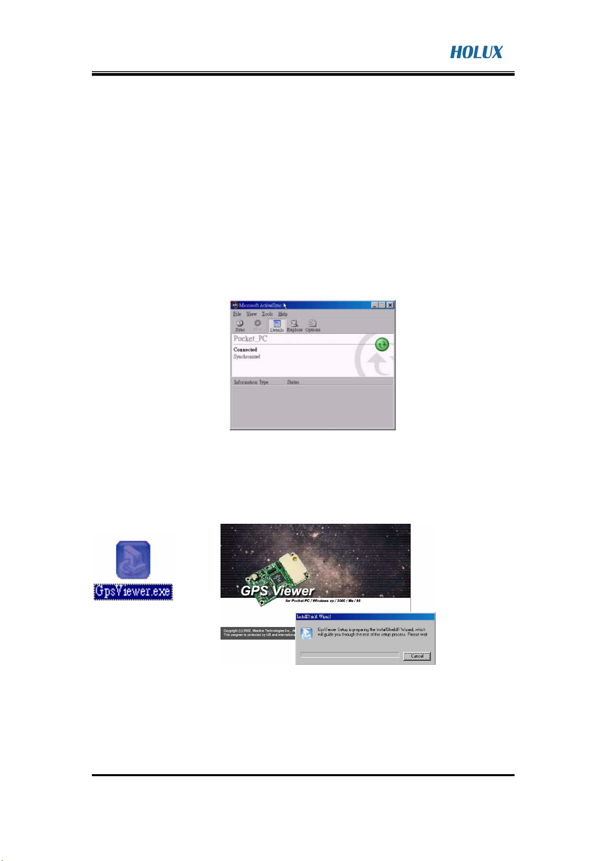
6. Operation and Test
The customers can use HOLUX GPSView.exe to test the engine board.
GPSViewer.exe is compatible with Microsoft Pocket PC or other operation
system alike.
1). Install Microsoft ActiveSync to your PC, refer to your Pocket PC
manual for installation procedure, as Fig. 6.1.
2). Setup your Pocket PC cradle to Desktop PC UART port. The Microsoft
ActiveSync will detect your Pocket PC automatically.
Setup your Pocket PC cradle to Desktop PC UART port. The Microsoft
ActiveSync will detect your Pocket PC automatically, as Fig. 6.1.
(Fig. 6.1)
3). Double click the GPSViewer.exe on your PC, then Holux
GPSViewer.exe program will install automatically, as Fig. 6.2.
(Fig. 6.2)
HOLUX Technology, Inc.
1F, No.30, R&D Road, Hsinchu 300, Taiwan (Hsinchu Science Industrial Park)
TEL: 886-3-6687000 FAX:886-3-6687111 E-mail:info@holux.com.tw Website:www.holux.com.tw
18
Page 19

GPS
Product series
4) Open “GPSViewer” on PC, as Fig. 6.3.
(Fig. 6.3)
5) The following window is show after executing
6) GPSViewer, as Fig. 6.4.
With HOLUX, You never lose the way!
(Fig. 6.4)
7) Setup Baud rate: 4800, then push “Scan” bottom to scan your COM
Port . Select your COM Port (COM1 ~ COM10), then push “Open GPN”
bottom, as Fig. 6.5, Fig. 6.6, and Fig. 6.7.
(Fig. 6.5) (Fig. 6.6) (Fig. 6.7)
HOLUX Technology, Inc.
1F, No.30, R&D Road, Hsinchu 300, Taiwan (Hsinchu Science Industrial Park)
TEL: 886-3-6687000 FAX:886-3-6687111 E-mail:info@holux.com.tw Website:www.holux.com.tw
19
Page 20

GPS
Product series
With HOLUX, You never lose the way!
8) Select “GPS Status” to show the satellite diagram like below, as Fig.
6.8.
(Fig. 6.8)
HOLUX Technology, Inc.
1F, No.30, R&D Road, Hsinchu 300, Taiwan (Hsinchu Science Industrial Park)
TEL: 886-3-6687000 FAX:886-3-6687111 E-mail:info@holux.com.tw Website:www.holux.com.tw
20
Page 21

GPS
Product series
With HOLUX, You never lose the way!
Appendix A : Reference Design
Fig A-1 is GR-89 connects to RS-232 transceiver solutions intended for
portable or hand-held applications such as notebook and palmtop computers.
(Fig A-1)
HOLUX Technology, Inc.
1F, No.30, R&D Road, Hsinchu 300, Taiwan (Hsinchu Science Industrial Park)
TEL: 886-3-6687000 FAX:886-3-6687111 E-mail:info@holux.com.tw Website:www.holux.com.tw
21
 Loading...