

Features
1/3 bias, 1/4 duty, 32´4 pattern,
·
3.0V LCD driver
14 kinds of built-in sound effects
·
General Description
HT113JA is a baseball LCD GAME designed by
HOLTEK. Apart from the IC's own 14 types of
special sound effects, the IC can work in con
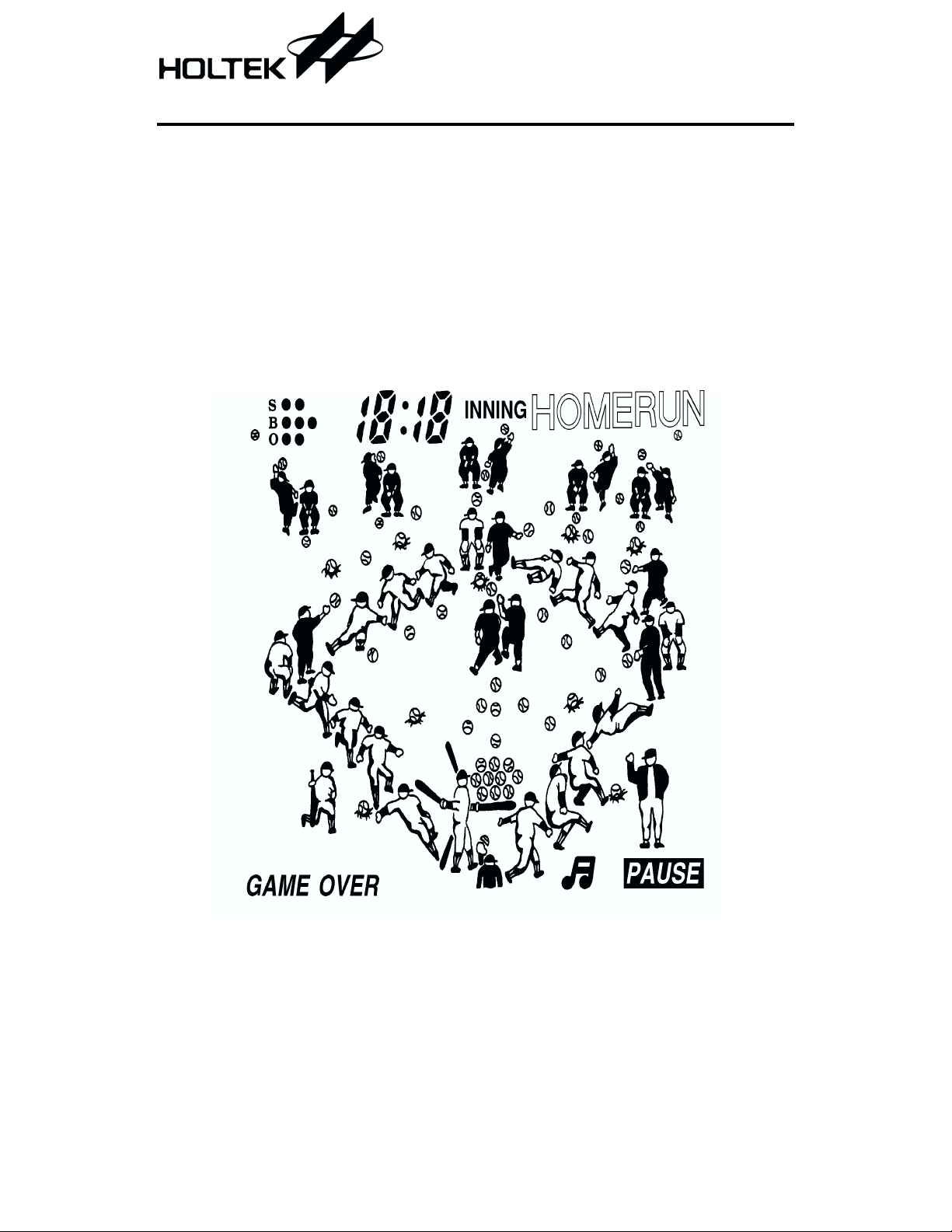
LCD Pattern
HT113JA
Baseball LCD Game
RC oscillator
·
Auto power off function
·
junction with the HT8121N voice IC to generate
play calls like "STRIKE", "BALL", "OUT", "HOME
RUN" and cheering.
-
1 December 14, 1999

Functional Description
Key description
·
RESET
Press this key and the whole system will re
start from the beginning. The score and stage
level are both cleared to zero. If the RESET
key and the A key are both pressed at the
same time, then the RESET key is released,
all LCD pattern dots are shown on the screen
for LCD testing.
·
START/PAUSE
This key has two functions. The function
START - above the slash - starts the game.
After the system restarts, or the game is over
or in free run mode, pressing this key starts a
new game with a short musical accompani
ment. Then, the game starts. When the game
is in progress, pressing this key can tempo
rarily stop the game. Pressing it again can re
sume the game.
·
MUTE
This is a sound effect switch. Pressing it once
can turn off the sound. Pressing it again
switches it on.
·
A
There are three functions to save:
¨
Pressing this key can set the LEVEL before
the contest.
¨
Pressing this key can retrieve the ball.
¨
Pressing this key can pitch a ball.
·
B
In defense, pressing the Left/Right key and
this key can pitch a ball.
·
Direction key. In offense, pressing it can make
the runner run from the first base to the sec
ond base. In defense, pressing it can pass the
ball to the second base.
·
¯
Direction key. In offense, pressing it can make
the runner run from the third base to home
base. In defense, pressing it can pass the ball
to home base.
·
®
Right direction key. When the player's pitcher
is pitching, holding this key can make the ball
-
veer to the right. Then, pressing A key or B
key can either pitch an outside corner good
ball or an outside corner bad ball. When the
outfielder is passing the ball, pressing this
key can pass the ball to the first base.
Pressing this key can also shift the outfielder
to the right to catch a flying ball.
·
¬
Left direction key. In offense, pressing this
key can make the runner run to the third
base. When the player's pitcher is pitching,
holding this key can make the ball veer to the
-
left. Pressing A key or B key can pitch an in
side corner good ball or an inside corner bad
-
-
ball. When the outfielder is passing the ball,
pressing this key can pass the ball to the third
base. Pressing this key can also shift the out
fielder to the left to catch a flying ball.
·
ON/OFF
Power switch. Press it once to turn on the
power; press it once again to turn off the
power; and so forth.
Operational description
·
Press the ON/OFF key to turn on the power
and the screen shows a pitch-catch practice.
Press the A key to decide on the play level of
the contest which is shown on the scoreboard.
LEVEL 2 indicates higher hitting rate for the
opponent's team during a game. Press the
START key at any time to start the game. If
no key is pressed within 15 seconds before the
START key is pressed, it automatically goes
into free-run mode. The system automatically
-
operates the game. Press the A key at any
time to select the required LEVEL or the
START key to start the game. If no key is
pressed within 4.5 minutes, the power is auto
matically turned off. If it is preferred to re
main in free-run mode, press any key before
auto power off so the time is recalculated.
HT113JA
-
-
-
-
2 December 14, 1999

HT113JA
·
Press the START key and the game starts. The
"1" innings on the screen flashes to show that
it is in the first innings. START music is played.
When the music is finished, the game starts
and the scoreboard shows 0:0. The player is first
to bat and by pressing the A key can take prac
tice swings. From that point on, the opponent s
pitcher is pitching and the catcher is catching,
only one swing of the bat is allowed. If the ball is
not struck, it is counted as strike. The decision
whether strike or ball follows the regular rules
of modern baseball. "S", "B", "O" on the upper
left corner of the screen represents "Strike",
"Ball" and "Out". Whenever a strike is made, a
dot is added after the "S" mark to record a
strike. At the same time, sound effects generate
a "strike" call, and an "OUT" call. When there
are 3 strikes, the player is out and "O" records
one out on the upper left of the screen. When
ever a ball is pitched, a dot is added after the "B"
mark to record a ball. At the same time, "ball"
call is generated. When one player is out, a spe
cial sound is played. When three players are
out, this inning is over. The inning number on
the scoreboard flashes on the screen for several
seconds and then it goes into the next round of
play.
·
When the ball is hit or there are four bad
strikes the batter runs to the first base, the
player automatically runs to the base. But it
can be controlled only once. If the player is at
offense and orders the runner to run continuously, press the direction key to shift it to the
next base (refer to the Key Description). During the running, the runner cannot run backward.
·
Foul ball is counted as a strike and a sound ef
fect is played. If there are already two strikes,
it is not taken into account.
·
When the batting side hits a ball along the
ground, the opposing side automatically
catches that ball and throws it, when the player
is defending, a ground ball is always caught.
The player will hear a "Boo" sound to signify
that the ball is in the fielder's glove. Then, press
one of the direction keys to pass the ball to a
base (refer to the Key Description). If the
player does not pass, the opponent will decide
if he/she should continue to run to the next
base depending upon the distance of the ball
from the batter.
·
When the ball is hit into the air, it is accompa
-
nied by a sound effect appropriate to a high
ball. If the opponent are fielding, and the last
batter's ball is caught, any player that has be
gun a run or has reached the next base, is au
-
-
tomatically returned to the base from which
he ran. If the player's side is fielding, the
player must press the Left/Right direction
keys in order to move the fielder to a suitable
position so that he/she can catch the high ball.
If a fielder misses a catch, the fielder then
runs to pick up the ball, after which a simu
lated crowd call will make a "Boo" sound to
signify that the ball is in the fielder's mitt.
-
-
Then, the ball can be passed to the most ap
propriate fielder (including the pitcher).
·
When there is a HOME RUN, the game will
generate a home run sound and a cheering
-
sound. The runner runs back to home base
while music is played. When the score is an
nounced, music is played.
·
When the runner is caught, the base from
where ran flashes. The voice IC plays the
"OUT" sound and the number of caught runners is recorded in the upper left hand corner
of the screen.
·
Whenever a runner either from the opponent
or defense stops, a five second timer is
started. During this 5-second interval, if the
direction keys are not pressed the inning
number on the scoreboard flashes on the
screen for several seconds and then the sys
-
tem automatically operates the game.
·
The second part of each inning the player
-
plays defense. Press a direction key, A key
and B key to control the pitching. There are
five kinds of trajectory for the ball to follow:
¨
Straight ball: Directly press A key or B key,
but direction key is not pressed.
¨
Inside corner strike: Press ¬ key and then
press A key.
¨
Outside corner strike: Press ® key and then
press A key.
3 December 14, 1999

HT113JA
¨
Inside corner ball: Press ¬ key and then
press B key.
¨
Outside corner ball: Press ® key and then
press B key.
·
If the player does not pitch within 7 seconds
during his turn at defense, the pitcher will
pitch a straight ball.
·
If the score is even after the 9th inning, the
match can be extended to a maximum of 19 in
nings.
·
There are various ways to finish a game:
¨
When the first part of the 7th inning is over,
or the second part of the 7th and 8th inning
is proceeding and the player's score is less
than the opponent's by 10 or more points.
¨
The second part or the 7th or 8th inning is
over and the player's score is higher than
the opponent's by 10 or more points.
¨
The first part of the 9th inning is over or the
second part of the 9th inning is proceeding,
and the player's score is less than that of the
opponent's.
¨
The second part of the 9th inning or above is
over and the player's score is higher than
that of the opponent's.
¨
When the score reaches 19.
¨
The second part of the 19th inning is over.
·
When the game is over, the screen reverts to
the very beginning prior to the start. "GAME
OVER" flashes on the bottom left corner. The
result is shown on the scoreboard. At this
point, the player can restart the game.
·
Auto power off function: HT113JA has an
auto power off function. It has a countdown
time of 4.5 minutes. If no key is pressed
within 4.5 minutes, power is automatically
turned off to save energy. When power is off,
press the ON/OFF key to turn it on. If any key
is pressed before auto power off, the count
down is restarted.
·
Pause function
¨
During the game, press the PAUSE key at
any time to stop the game. At this moment,
the screen is frozen. Only "PAUSE" and the
umpires are flashing relatively. Press the
PAUSE key again, then the game contin
ues.
¨
If the power has been switched off in the
PAUSE mode (automatically or manually),
the system will automatically save the
screen. When power is turned on again, it
will go back to the frozen screen. Press the
PAUSE key again and the game continues.
·
-
Displaying the scoreboard
The level, inning, or score will be shown on
the scoreboard at the proper time according to
the following:
¨
LEVEL
Press Key A before the START key is
pressed. It will show LEVEL 1 or LEVEL 2
(if not set, LEVEL 1 is assigned). The dis
play looks like L:1 or L:2.
¨
INNING
Conditions wherein the innings flashes are
as follows:
-
After pressing the START key
-
Changing defense/offense position
-
During the game time, runner stops run
ning and the defender stops passing the
ball for 5 seconds.
¨
SCORE
This is the player's score, the right one is
the opponent's score. The highest score ratio is 19:19. It is shown in the following situation:
-
0:0 is shown in pitching practice.
-
Score is shown after flashing inning.
-
When the game is over, score is shown.
Counting method
Counting method is in accordance with regular
baseball rules.
-
Sound effects
·
HT113JA consists of 14 kinds of sound effects.
¨
Sound for hitting the ball
¨
Sound for high ball
¨
Sound for STRIKE
¨
Sound for BALL
-
-
-
4 December 14, 1999
HT113JA
¨
Sound for moving the ball
¨
Music for changing defense/offense position
¨
Sound for HOME RUN
¨
Sound for ball being placed in a fielder s
mitt
¨
Sound for winning points
¨
Sound for "OUT"
¨
Sound for a foul ball
¨
START music
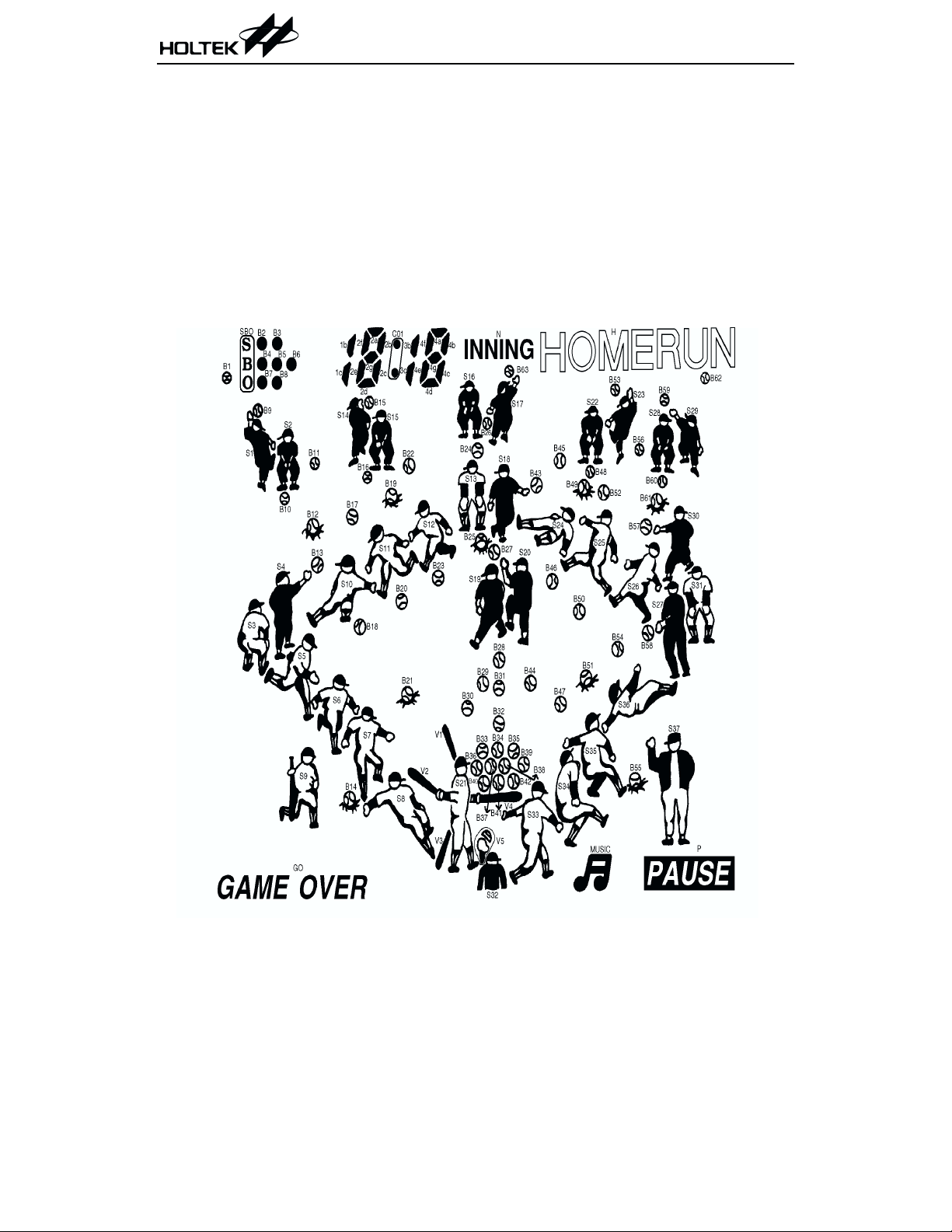
LCD Display Label
¨
Music for pitching practice
¨
Running base music in HOME RUN
·
Operating with HT8121N to produce these
four sounds
¨
STRIKE
¨
BALL
¨
OUT
¨
HOME RUN and Cheering sound
5 December 14, 1999

HT113JA
LCD Pattern Contrast Table
Pad No. Pin No. COM0 COM1 COM2 COM3 SEGMENT
536
635
734
8 33 COM0
34 32 CO1 B15 B19 B22 SEG0
35 31 3bc 4f 4d 4e SEG1
36 30 4a 4b 4c 4g SEG2
37 29 N S16 S13 B24 SEG3
38 28 B63 S17 S18 B26 SEG4
39 27 H B53 B43 B45 SEG5
40 26 S23 S22 B49 B48 SEG6
41 25 S29 S28 B61 B60 SEG7
42 24 B62 B59 B57 B56 SEG8
43 23 P S31 S30 S27 SEG9
44 22 M S37 S26 B58 SEG10
45 21 B55 S36 B52 B54 SEG11
46 20 S35 B51 S25 B50 SEG12
47 19 S34 B47 S24 B46 SEG13
48 18 S33 B44 B28 B31 SEG14
49 17 B42 B39 B29 B35 SEG15
50 16 S32 B41 B32 B38 SEG16
51 15 V4 B40 B34 B37 SEG17
52 14 V5 B36 B30 B33 SEG18
53 13 S21 V1 B27 S20 SEG19
54 12 V3 V2 B25 S19 SEG20
55 11 S8 B21 S12 B23 SEG21
56 10 B14 S7 B20 S6 SEG22
57 9 GO S5 B13 S4 SEG23
58 8 S9 S3 B10 B12 SEG24
59 7 B1 SBO S1 B9 SEG25
60 6 B2 B4 S2 B7 SEG26
61 5 B3 B5 B11 B8 SEG27
62 4 B6 B17 B18 S10 SEG28
63 3 S14 S15 S11 B16 SEG29
64 2 1bc 2f 2d 2e SEG30
65 1 2a 2b 2c 2g SEG31
¾¾¾
¾¾
¾
COM1
¾¾¾
COM2
¾¾
COM3 COM3
¾
COM2
COM1
COM0
6 December 14, 1999

HT113JA
LCD Package Outline Unit : mm
41.0 M in. View ing Area
32.0 M in. View ing Area
10.0 M ax.
38.0
40.0± 0.3
±
0.3
Pin1 Pin36
Max. 1.0
Pitch 1.2
47.0
0.6
35 = 42
´
±0.
0.6
3
Specifications
Top polarizer: Transmissive (46.00mm´39.00mm)
Bottom polarizer: Transmissive (46.00mm´37.00mm)
Storage temperature: -20°Cto70°C
Operating temperature: -10°Cto60°C
Viewing angle: 6 o'clock
Drive condition: 3V, 1/4 duty, 1/3 bias
Display mode: Tn, normal type
2.5
1.1±0.1
2.0
1.1
0.1
±
7 December 14, 1999

Pad Assignment
VDD
HT113JA
SEG22
SEG20
SEG23
SEG24
SEG25
SEG26
SEG27
SEG28
SEG29
SEG30
SEG31
SEG19
SEG21
SEG18
BZ
BZ
VLCD
T256
COM 3
COM 2
COM 1
COM 0
NC
NC
NC
NC
START/PAU SE
MUTE
ON/OFF
NC
60
24
KEY3
59
25
KEY2
58
(0 ,0 )
26
KEY1
21
OSCO
62 63 64
22
T1D
61
23
KEY4
65
66
1
2
3
4
5
6
7
8
9
10
11
12
13
®
14
¬
15
16
17
18
19
20
OSCI
VSS
27
56 57
28
¯
55
29
B
54
30
A
31
NC
52 53
32
RESET
51
50
49
48
47
46
45
44
43
42
41
40
39
38
37
36
35
34
33
SEG17
SEG16
SEG 15
SEG14
SEG13
SEG12
SEG11
SEG10
SEG9
SEG8
SEG 7
SEG6
SEG 5
SEG 4
SEG 3
SEG 2
SEG 1
SEG 0
NC
Chip size: 2780´2990 (mm)
2
* The IC substrate should be connected to VSS in the PCB layout artwork.
8 December 14, 1999

HT113JA
Pad Coordinates
Pad No. X Y Pad No. X Y
1
2
3
4
5
6
7
8
9
10
11
12
13
14
15
16
17
18
19
20
21
22
23
24
25
26 124.90
27 284.90
28 427.40
29 570.90
30 713.40
31 856.90
32 999.40
33 1261.10
-1192.10
-1192.10
-1196.70
-1261.10
-1261.10
-1261.10
-1261.10
-1261.10
-1261.10
-1261.10
-1261.10 -126.80
-1261.10 -270.30
-1261.10 -412.80
-1261.10 -556.30
-1261.10 -698.80
-1261.10 -842.30
-1261.10 -984.80
-1261.10 -1128.30
-876.70 -1331.40
-719.70 -1331.40
-542.10 -1241.00
-406.70 -1241.00
-276.30 -1241.00
-140.90 -1241.00
-10.50 -1241.00
1305.20 34 1261.10
1169.80 35 1261.10
1019.80 36 1261.10
873.70 37 1261.10
731.20 38 1261.10
587.70 39 1261.10
445.20 40 1261.10
301.70 41 1261.10
159.20 42 1261.10 21.70
15.70 43 1261.10 164.20
44 1261.10 307.70
45 1261.10 450.20
46 1261.10 593.70
47 1261.10 736.20
48 1261.10 879.70
49 1261.10 1022.20
50 1261.10 1165.70
51 1261.10 1311.20
52 1001.00 1331.40
53 858.50 1331.40
54 715.00 1331.40
55 572.50 1331.40
56 429.00 1331.40
57 286.50 1331.40
58 143.00 1331.40
-1241.00
-1331.40
-1331.40
-1331.40
-1331.40
-1331.40
-1331.40
-1265.80
59 0.50 1331.40
60
61
62
63
64
65
66
-143.00
-285.50
-429.00
-571.50
-715.00
-857.50
-990.50
Unit: mm
-1122.30
-979.80
-836.30
-693.80
-550.30
-407.80
-264.30
-121.80
1331.40
1331.40
1331.40
1331.40
1331.40
1331.40
1331.40
9 December 14, 1999

Absolute Maximum Ratings
HT113JA
Supply Voltage..............................-0.3V to 5.5V
Input Voltage .................V
-0.3V to VDD+0.3V
SS
Storage Temperature.................-50°Cto125°C
Operating Temperature ..................0°Cto70°C
Note: These are stress ratings only. Stresses exceeding the range specified under Absolute Maxi
mum Ratings may cause substantial damage to the device. Functional operation of this de
vice at other conditions beyond those listed in the specification is not implied and prolonged
exposure to extreme conditions may affect device reliability.
Electrical Characteristics
Ta=25°C
Test Conditions
Symbol Parameter
V
I
DD
I
STB
V
f
SYS
DD
LCD
Operating Voltage
Operating Current 3V
Standby Current 3V System halt
LCD Supply Voltage 3V
Operating Frequency 3V
DD
Conditions
V
¾¾
No load,
f
=512kHz
SYS
¾¾3¾
R=36kW¾
Min. Typ. Max. Unit
2.4 3 3.3 V
¾
¾
300 500
15
mA
mA
V
512
¾
kHz
-
-
10 December 14, 1999

Application Circuits
Speaker application with voice
COM0 COM1 COM2 COM3
47
W
3V
47mF
10mF
0.1
m F
START/PAUSE
MUTE
ON/OFF
HT113JA
LCD PANEL
SEG 0~SEG31
5k
W
®
¬
9
10
11
12
13
14
15
16
17
18
1
3
58
59
60 52 61 53 62 54 63 55 64 56 65 57 66
H T113JA
19
20
21
22
23
24
25 2 26
27 4 28 5 29 6 30 7 31 8 32
51
50
49
48
47
46
45
44
43
42
41
40
39
38
37
36
35
34
33
8
W
SPK
8050
300k
1N 4148
W
AUD
OSCO
OSCI
VDD
1
2
3
4
6
VSS
H T8121N
10
KEY4
KEY3
9
KEY2
8
KEY1
7
Note: The capacitor in dash block is recommended.
The IC substrate should be connected to VSS in the PCB layout artwork.
11 December 14, 1999
f=512kHz
36k
W
BA
®
¬
RESET
0.1mF

Speaker application without voice
COM0 COM1 COM2 COM3
HT113JA
LCD PANEL
3V
8050
F
m
4.7
5k
W
START/PAU SE
MUTE
ON/OFF
0.1
m
F
1
3
9
10
11
12
®
¬
13
14
15
16
17
18
19
20
f=512kH z
21
22
36k
23
W
SEG 0~SEG31
58
59
60 52 61 53 62 54 63 55 64 56 65 57 66
H T113JA
25 2 26
24
27 4 28 5 29 6 30 7 31 8 32
A
B
®
¬
51
50
49
48
47
46
45
44
43
42
41
40
39
38
37
36
35
34
33
RESET
0.1mF
Note: The capacitor in dash block is recommended.
The IC substrate should be connected to VSS in the PCB layout artwork.
12 December 14, 1999

Buzzer application without voice
COM0 COM1 COM2 COM3
VDD
HT113JA
LCD PANEL
SEG 0~SEG31
3V
START/PAU SE
ON/OFF
MUTE
B uzzer
®
¬
9
10
11
12
13
14
15
16
17
18
1
3
19
20
f=512kH z
21
22
36k
60 52 61 53 62 54 63 55 64 56 65 57 66
H T113JA
23
24
W
58
59
25 2 26
27 4 28 5 29 6 30 7 31 8 32
®
51
50
49
48
47
46
45
44
43
42
41
40
39
38
37
36
35
34
33
RESET
A
B
¬
0.1mF
Note: The IC substrate should be connected to VSS in the PCB layout artwork.
13 December 14, 1999

HT113JA
Holtek Semiconductor Inc. (Headquarters)
No.3 Creation Rd. II, Science-based Industrial Park, Hsinchu, Taiwan, R.O.C.
Tel: 886-3-563-1999
Fax: 886-3-563-1189
Holtek Semiconductor Inc. (Taipei Office)
5F, No.576, Sec.7 Chung Hsiao E. Rd., Taipei, Taiwan, R.O.C.
Tel: 886-2-2782-9635
Fax: 886-2-2782-9636
Fax: 886-2-2782-7128 (International sales hotline)
Holtek Semiconductor (Hong Kong) Ltd.
RM.711, Tower 2, Cheung Sha Wan Plaza, 833 Cheung Sha Wan Rd., Kowloon, Hong Kong
Tel: 852-2-745-8288
Fax: 852-2-742-8657
Copyright Ó 1999 by HOLTEK SEMICONDUCTOR INC.
The information appearing in this Data Sheet is believed to be accurate at the time of publication. However, Holtek
assumes no responsibility arising from the use of the specifications described.The applications mentionedherein are
used solely for the purpose of illustration and Holtek makes no warranty or representation that such applications
will be suitable without further modification, nor recommends the use of its products for application that may pres
ent a risk to human life due to malfunction or otherwise. Holtek reserves the right to alter its products without prior
notification. For the most up-to-date information, please visit our web site at http://www.holtek.com.tw.
14 December 14, 1999
-
 Loading...