

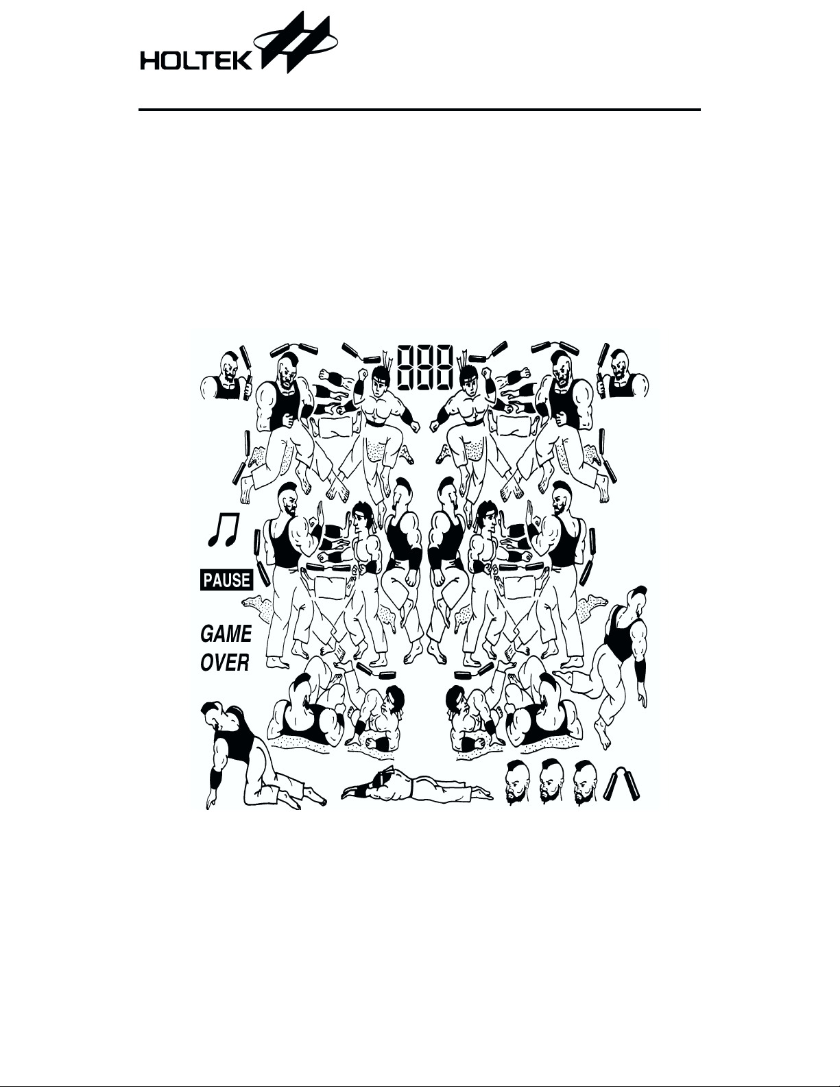
²Streetfighters² LCD Game
Features
1/3 bias, 1/4 duty, 32 ´ 4 pattern,
·
3.0V LCD driver
13 different sound effects
·
General Description
The HT113AA is a game controller IC designed
by Holtek. In this game the player and the en
emy or the computer, compete against each
LCD Pattern
HT113AA
RC oscillator
·
Auto power off function
·
other for the prize. The player can use both
kicks and punches in this streetfighting game
to attack the enemy.
1 December 14, 1999

Functional Description
HT113AA
Key description
·
RESET
This key resets the game and clears any pre
viously recorded score. If the PUNCH and
RESET keys are pressed simultaneously and
then the RESET key is released while still
holding the PUNCH key, all the LCD patterns
will be displayed for testing purposes.
·
START/PAUSE
If the game is in the demonstration mode or at
the GAME OVER stage, pressing this key
starts the game. If play has commenced,
pressing this key temporarily stops the game.
If it is pressed again the game continues.
·
MUTE
This key controls the sound effects. Its toggle
action alternately turns the sound on or off.
·
ON/OFF
This key controls the power supply to the IC.
Its toggle action alternately turns the game
on or off.
·
Moves the player up.
·
¯
Moves the player down.
·
¬
Moves the player to the left.
·
®
Moves the player to the right.
-
·
Punch/Mode
This key serves two functions, one is for punch
ing the opponent and the other is to set the
mode of the game. Before the game starts this
key can be used to select one of the four playing
modes. After the game has started this key is
used to enable the player to punch the oppo
nent.
·
Kick
This key is used to enable the player to kick
the opponent.
Operation
·
After pressing the ON/OFF switch to turn on
the power supply, the game will immediately
enter the demonstration mode. The game will
demonstrate how the player and enemy fig
ures fight. The highest score will also be dis
played. If Punch/Mode is pressed the game
mode can be chosen which is then represented
by the number of heads shown at the bottom
right corner of the screen.
¨
Mode 1
One head displayed- one enemy to fight
with.
¨
Mode 2
Two heads displayed- two enemies to fight
with.
¨
Mode 3
Three heads and one weapon displayedthree enemies to fight with.
¨
Mode 4
No mode indicator is displayed. The game
moves from mode 1, mode 2 to mode 3 after
each game has been won.
-
-
-
-
2 December 14, 1999

HT113AA
·
After selecting the playing mode, pressing the
START/PAUSE key will first play the prelude
music before the game starts.
·
In mode 1 there is only one enemy figure. The
player can use the left, right, up and down
keys to move the figure to the best position
then use the PUNCH or KICK key to attack
the enemy.
·
If the playing figure is attacked by the enemy
figure it will immediately fall down. When
this happens the player must press the up key
to recover or be subjected to continuous at
tacks.
·
When the enemy¢s score reaches zero the
game objective has been reached and the
overall score will be increased by one. Every
playing mode has a maximum score of 99.
When this has been reached it will remain at
this value and not increase any more.
·
If the player¢s score reaches zero, the game
will end and the overall score will be recorded.
The flashing game over message will be dis
played.
·
In mode 2, there are two enemies that have to
be attacked and destroyed to win the game.
·
In mode 3, aside from the two main enemy figures there is an additional enemy figure holding a weapon who can attack the player. The
player cannot attack this enemy, and can only
dodge out of his way.
·
In mode 3 this third enemy figure with the
weapon can appear at any time on the top left
or right side of the screen. This enemy figure
is able to work out the best place to attack the
player who must be careful to dodge out of the
way.
·
Mode 4 combines all the three modes.
Starting from mode 1, after the game has
been won or the barrier reached, the game
will then move to mode 2, then to mode 3.
·
The higher the overall score the faster the en
-
emy figure¢s actions will be.
·
In modes 2 and 3, the second enemy figure
will attack from behind, so the player must be
careful to dodge out of the way.
·
The displayed data have the following
-
meaning ...
¨
During the demonstration mode, the play
ing mode will be displayed at the bottom of
the screen and the recorded overall score at
the top of the screen. The mode number cor
responds to the number of heads displayed.
¨
When the game starts, the overall score will
be displayed while the prelude music is
playing.
¨
When the game is playing the score of both
the player and opponent will be shown. The
-
player¢s score is displayed at the left while
the opponent or enemy¢s score is displayed
at the right. The objective is to reduce the
enemy¢s score to zero.
·
If no key has been pressed for 2 minutes then
the game will automatically be turned off,
however the overall game score will be retained.
·
The MUTE switch will silence the sound effects.
3 December 14, 1999

HT113AA
·
The START/PAUSE key will put the game
into a temporary wait state. The conditions of
the game prior to pressing this key will be re
tained even if the game has been switched off
manually or automatically. When the game is
again started, the player can resume from
where it stops when the START/PAUSE key
was initially pressed. If the machine is
switched off outside of this temporary wait
state then the conditions of the present game
will not be stored and the game has to start
from the beginning.
·
When the game is over the message ²GAME
OVER² will flash on the screen and the game
will enter a wait state. Pressing the
START/PAUSE key will allow a new game to
start or pressing the PUNCH/MODE key will
allow a new mode of playing to be chosen. Or
press ON/OFF to switch off. If within 30 sec
onds no key has been pressed the system will
begin to free run in the demonstration mode.
·
The ON/OFF switch controls the power supply.
Calculating the score
·
When the game begins both the player and
enemy¢s score is 9.
·
Every punch, kick or weapon hit (mode 3) will
initially mean a reduction of the opponent¢s
score by one. But the actual score deducted is
dependent upon the opponents score. If the
opponents score is 9 then 0.9 will be deducted,
if the opponents score is 8 then 0.8 will be deducted and so on in the same way. However
due to the limitations of the LCD pattern the
decimal number will not be shown.
·
-
·
Sound effects
·
-
If within 7 seconds no attack is made then the
score will be increased by one but only up to a
maximum of 9. This applies to both player
and opponent.
When the opponent¢s score has been reduced
to 0, the objective of the present game has
been reached. When the player¢s score
reaches zero, the game is over.
The IC has 13 sound effects
¨
Sound corresponding to the mode
¨
When the player is attacked
¨
When the weapon is about to be used
¨
When the weapon is thrown
¨
When the weapon hits the player
¨
When the player kicks
¨
When the player throws a punch
¨
When the enemy kicks
¨
When the enemy throws a punch
¨
When the game objective has been reached
¨
When the game begins
¨
When the game ends
¨
Background sound effect
4 December 14, 1999

LCD Display Table
HT113AA
LCD Pattern Contrast Table
Pad No. Pin No. COM0 COM1 COM2 COM3 SEGMENT
536
635
734
8 33 COM0
34 32 A32 B32 C32 D32 SEG0
35 31 A31 B31 C31 D31 SEG1
¾¾¾
¾¾
¾
COM1
¾¾¾
5 December 14, 1999
COM2
¾¾
COM3 COM3
¾
COM2
COM1
COM0

HT113AA
Pad No. Pin No. COM0 COM1 COM2 COM3 SEGMENT
36 30 A30 B30 C30 D30 SEG2
37 29 A29 B29 C29 D29 SEG3
38 28 A28 B28 C28 D28 SEG4
39 27 A27 B27 C27 D27 SEG5
40 26 A26 B26 C26 D26 SEG6
41 25 A25 B25 C25 D25 SEG7
42 24 A24 B24 C24 D24 SEG8
43 23 A23 B23 C23 D23 SEG9
44 22 A22 B22 C22 D22 SEG10
45 21 A21 B21 C21 D21 SEG11
46 20 A20 B20 C20 D20 SEG12
47 19 A19 B19 C19 D19 SEG13
48 18 A18 B18 C18 D18 SEG14
49 17 A17 B17 C17 D17 SEG15
50 16 A16 B16 C16 D16 SEG16
51 15 A15 B15 C15 D15 SEG17
52 14 A14 B14 C14 D14 SEG18
53 13 A13 B13 C13 D13 SEG19
54 12 A12 B12 C12 D12 SEG20
55 11 A11 B11 C11 D11 SEG21
56 10 A10 B10 C10 D10 SEG22
57 9 A9 B9 C9 D9 SEG23
58 8 A8 B8 C8 D8 SEG24
59 7 A7 B7 C7 D7 SEG25
60 6 A6 B6 C6 D6 SEG26
61 5 A5 B5 C5 D5 SEG27
62 4 A4 B4 C4 D4 SEG28
63 3 A3 B3 C3 D3 SEG29
64 2 A2 B2 C2 D2 SEG30
65 1 A1 B1 C1 D1 SEG31
6 December 14, 1999

HT113AA
LCD Package Outline Unit : mm
4 1 .0 m in . v ie w in g a re a
0 .3
0 .3
±
±
10.0 m ax.
1.0 m ax.
Pin1 Pin36
0.6 0.6
Pitch 1.2 ´ 35= 42
0 .3
47.0
±
2.5
32.0 m in. viewing area
1.1
0 .1
±
1.1 ± 0 .1
40.0
38.0
7 December 14, 1999

Pad Assignment
VDD
HT113AA
SEG 18
SEG 19
SEG 20
SEG 22
SEG 23
SEG 24
SEG 25
SEG 26
SEG 27
SEG 28
SEG 29
SEG 30
SEG 31
SEG 21
BZ
VLCD
T256
COM 3
COM 2
COM 1
COM 0
NC
NC
NC
NC
START/PAUSE
MUTE
ON/OFF
NC
BZ
®
¬
4
5
6
7
8
9
10
11
12
13
14
15
16
17
18
54 55
PUNCH
31
NC
52 53
32
RESET
51
50
49
48
47
46
45
44
43
42
41
40
39
38
37
36
35
34
33
SEG17
SEG16
SEG15
SEG14
SEG13
SEG12
SEG11
SEG10
SEG9
SEG8
SEG7
SEG6
SEG5
SEG4
SEG3
SEG2
SEG1
SEG0
NC
26
NC
56 57 58 59 60
27 28
¯
¯
29 30
KICK
62 63 64 65 66
21
OSCO
22
T1D
61
23
NC
24
NC
(0 ,0 )
25
NC
1
2
3
19
20
OSCI
VSS
Chip Size : 2780 ´ 2990 (mm)
2
* The IC substrate should be connected to VSS in the PCB layout artwork.
8 December 14, 1999
HT113AA
Pad Coordinates
Pad No. X Y Pad No. X Y
1
2
3
4
5
6
7
8
9
10
11
12
13
14
15
16
17
18
19
20
21
22
23
24
25
26 124.90
27 284.90
28 427.40
29 570.90
30 713.40
31 856.90
32 999.40
33 1261.10
-1192.10
-1192.10
-1196.70
-1261.10
-1261.10
-1261.10
-1261.10
-1261.10
-1261.10
-1261.10
-1261.10 -126.80
-1261.10 -270.30
-1261.10 -412.80
-1261.10 -556.30
-1261.10 -698.80
-1261.10 -842.30
-1261.10 -984.80
-1261.10 -1128.30
-876.70 -1331.40
-719.70 -1331.40
-542.10 -1241.00
-406.70 -1241.00
-276.30 -1241.00
-140.90 -1241.00
-10.50 -1241.00
1305.20 34 1261.10
1169.80 35 1261.10
1019.80 36 1261.10
873.70 37 1261.10
731.20 38 1261.10
587.70 39 1261.10
445.20 40 1261.10
301.70 41 1261.10
159.20 42 1261.10 21.70
15.70 43 1261.10 164.20
44 1261.10 307.70
45 1261.10 450.20
46 1261.10 593.70
47 1261.10 736.20
48 1261.10 879.70
49 1261.10 1022.20
50 1261.10 1165.70
51 1261.10 1311.20
52 1001.00 1331.40
53 858.50 1331.40
54 715.00 1331.40
55 572.50 1331.40
56 429.00 1331.40
57 286.50 1331.40
58 143.00 1331.40
-1241.00
-1331.40
-1331.40
-1331.40
-1331.40
-1331.40
-1331.40
-1265.80
59 0.50 1331.40
60
61
62
63
64
65
66
-143.00
-285.50
-429.00
-571.50
-715.00
-857.50
-990.50
Unit : mm
-1122.30
-979.80
-836.30
-693.80
-550.30
-407.80
-264.30
-121.80
1331.40
1331.40
1331.40
1331.40
1331.40
1331.40
1331.40
9 December 14, 1999

Absolute Maximum Ratings
HT113AA
Supply Voltage .......................VDD-0.3V to 5.5V
Input Voltage .................V
-0.3V to VDD+0.3V
SS
Storage Temperature.................-50°Cto125°C
Operating Temperature ..................0°Cto70°C
Note: These are stress ratings only. Stresses exceeding the range specified under ²Absolute Maxi
mum Ratings² may cause substantial damage to the device. Functional operation of this device
at other conditions beyond those listed in the specification is not implied and prolonged expo
sure to extreme conditions may affect device reliability.
Electrical Characteristics
Ta=25°C
Test Conditions
Symbol Parameter
V
I
I
V
f
DD
DD
STB
LCD
SYS
Operating Voltage
Operating Current 3V
Standby current 3V system halt
LCD Supply Voltage 3V
Operating Frequency 3V
V
DD
Conditions
¾¾
No load,
f
= 512kHz
SYS
¾¾3¾
R= 36kW¾
Min. Typ. Max. Unit
2.4 3 3.3 V
¾
¾ 1
300 500
5mA
mA
V
512
¾
kHz
-
-
10 December 14, 1999
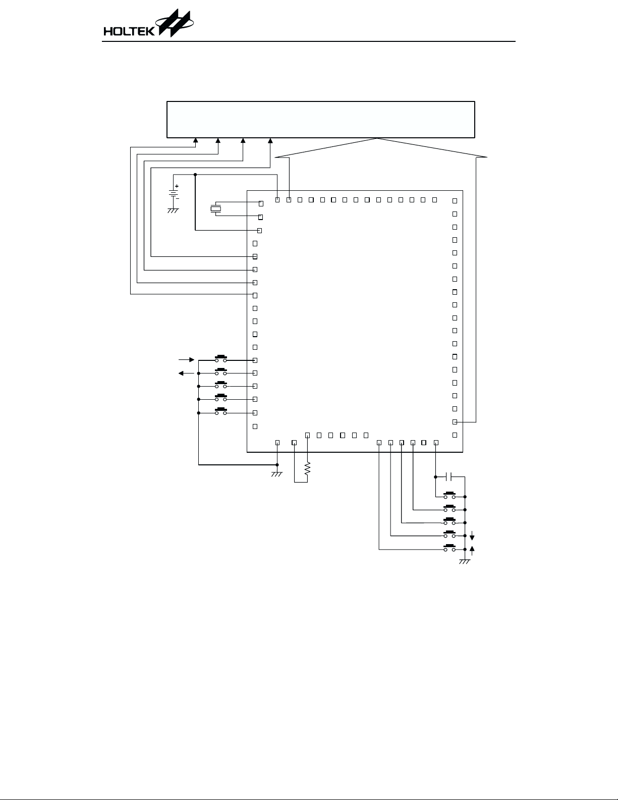
Application Circuits
Buzzer application
COM 0 COM1
HT113AA
LCD PANEL
COM 2 COM 3
S E G 0 ~ S E G 3 1
3V
START/PAUSE
MUTE
ON/OFF
B uzzer
4
5
6
7
8
9
10
11
12
13
14
15
16
17
18
1
2
3
19 20
H T113A A
21 22 23 24 25 26
36k
W
525354555657585960616263646566
27 28 29 30 31 32
51
50
49
48
47
46
45
44
43
42
41
40
39
38
37
36
35
34
33
0.1mF
f= 512kH z
Note: The IC substrate should be connected to VSS in the PCB layout artwork.
11 December 14, 1999
RESET
PUNCH
KICK

Speaker application
COM 0 COM1 CO M2
HT113AA
LCD PANEL
COM 3
Speaker
3V
8050
START/PAUSE
MUTE
ON/OFF
4.7mF
0.1mF
S E G 0 ~ S E G 3 1
31 32
51
525354555657585960616263646566
50
49
48
47
46
45
44
43
42
41
40
39
38
37
36
35
34
33
1
2
3
4
5
6
7
8
9
10
11
12
13
14
15
16
17
18
19
21 22 23 24 25 26
20
H T113A A
27 28 29 30
36k
W
f= 512kH z
Note: The capacitor in dash block is recommended.
The IC substrate should be connected to VSS in the PCB layout artwork.
12 December 14, 1999
0.1mF
RESET
PUNCH
KICK

HT113AA
Holtek Semiconductor Inc. (Headquarters)
No.3 Creation Rd. II, Science-based Industrial Park, Hsinchu, Taiwan, R.O.C.
Tel: 886-3-563-1999
Fax: 886-3-563-1189
Holtek Semiconductor Inc. (Taipei Office)
5F, No.576, Sec.7 Chung Hsiao E. Rd., Taipei, Taiwan, R.O.C.
Tel: 886-2-2782-9635
Fax: 886-2-2782-9636
Fax: 886-2-2782-7128 (International sales hotline)
Holtek Semiconductor (Hong Kong) Ltd.
RM.711, Tower 2, Cheung Sha Wan Plaza, 833 Cheung Sha Wan Rd., Kowloon, Hong Kong
Tel: 852-2-745-8288
Fax: 852-2-742-8657
Copyright Ó 1999 by HOLTEK SEMICONDUCTOR INC.
The information appearing in this Data Sheet is believed to be accurate at the time of publication. However, Holtek
assumes no responsibility arising from the use of the specifications described. The applications mentioned herein are
used solely for the purpose of illustration and Holtek makes no warranty or representation that such applications
will be suitable without further modification, nor recommends the use of its products for application that may pres
ent a risk to human life due to malfunction or otherwise. Holtek reserves the right to alter its products without prior
notification. For the most up-to-date information, please visit our web site at http://www.holtek.com.tw.
13 December 14, 1999
-
 Loading...