

Features
•
1/3 bias, 1/4 duty, 32×4 pattern,
3.0V LCD driver
•
Built-in sound generator
General Description
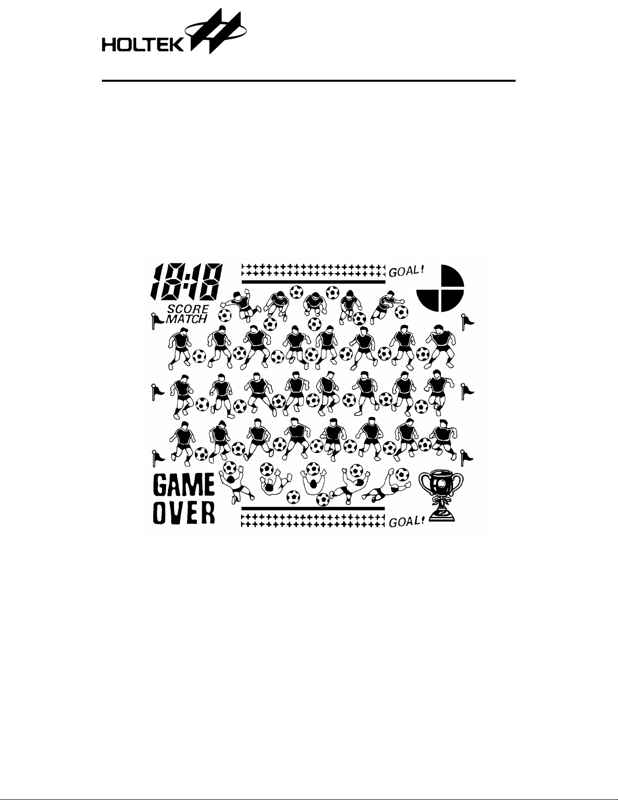
HT1136A is a football LC D GA ME de si gned by
HOLTEK. By using the play controls an exciting game can develop. In the defense, the player
LCD Pattern
HT1136A
Football LCD Game
•
RC oscillator
•
Auto power off mode
can control any team memb er; in offense, the
player can pass and kick as necessary.
1 17th Nov ’98

Functional Description
Key description
•
RESET
Press this key to re-initia lize the game. The
scoreboard is cleared to zero (data is lost) and
restarts the game from the beginning.
•
START/ON
When power is off, press this ke y to s tart the
game. When the game is in progress, pressing
this key has no effect.
•
MUTE
Pressing this ke y can turn off the music a nd
sound effects without disturbing the game.
Pressing it again restores the music and
sound effects.
•
OFF
Pressing this key at any time can turn off the
power. But the highest score is saved.
•
PAUSE
Pressing this key can temporarily stop the
game, freeze the screen and s top the sound
effects. Press it again and the game continues.
•
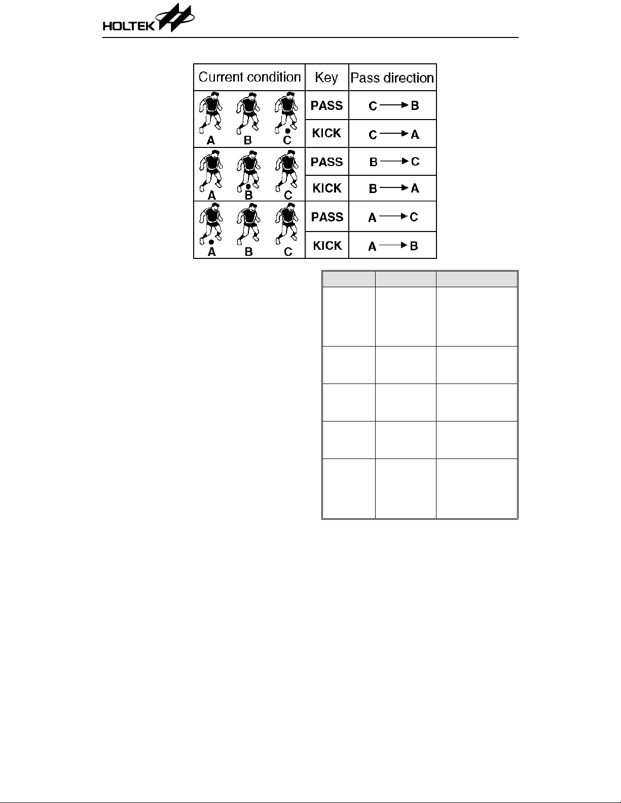
PASS
In defense, this key can control the team
members (which will be flashing) of the
player’s side. In offense, pressing this key can
pass the ball to the other team member in the
player’s side. The ball is passed in the direction given in the table.
•
KICK
In defense, this key can select a team member
on the player’s side, but it’s direction is different from the PASS key. For offense, if not in
the penalty area, pressing thi s key can pass
the ball to the other team member on the
player ’s side, but the pass direction is different from the PASS key. If within the penalty
area of the oppo ne nt’s side, it is goal shootin g
of which direction cann ot be controlled. The
ball is passed to the direction as ind icated in
the table.
HT1136A
•
UP
It moves the flashing team membe r upward.
If the flashing team member controls the ball,
the screen can go to the next.
•
DOWN
It makes the flashing team member move
down.
•
LEFT
It makes the flashing team member move to
the left, or controls the goal shooting direction
in the PK contest.
•
RIGHT
It makes the flashing team member move to
the right, or controls the goal shooting dire ction in the PK contest.
* At both sides’ penalty area, there are only two
team members. If in defense, it doesn’t matter
whether PASS or KICK key is pressed, it always
shifts the ball from one to the other team member.
In offense, at the other side’s penalty area, pressing the PASS key means to pass the ball to the
other team member , while pressing the KICK key
means “goal shooting”.
Operational desc r i p tion
•
Player assigns team members wearing dark
football shirts to contes t with the opponents
wearing light football shirts who is controlled
by the internal computer. Player’s team member should defend from the bottom to th e top
of the screen and defend the oppo nent’s goal
shooting at the bottom. During the contest,
opponents will use a lot of techniques to intercept the ball and approach the goal on the
bottom of the screen. Players can stop the
opponents and intercept the ball for a counterattack.
•
Press the START/ON key, the screen then
shows the highest score an d a prelude (start
music) is played. The highest score is shown
for 2 seconds and the current level is indicated. Press the START/ON key again and the
game starts. With a whistle sound, player
begins to attack.
2 17th Nov ’98
•
Each half lasts about 3 minutes. On the upper
right corner of the screen, there is a time
signal to remind the player how much time is
left. When only half a minute is left, the time
signal fl ashes. W hen tim e is up , the ga me is
over. If player’s score is higher than the opponent’s, a level is achieved and the passthrough-level music is played. The game goes
into the next level. If player’s score is l ower
than the opponent’s, the game is over and the
game-over music is played. When it is even, a
penalty kick contest is added to decide who is
the winner. During the contest, if one side is
winning by 5 goals, the game is over.
•
The football field is divid e d into five sectio ns .
Only one section can be seen on the scree n.
The five sections are first half, second half,
third half and both sides’ penalty areas. It is
indicated by flags and goal nets.
HT1136A
Section Sign Team member
Two team
Opponent’s
penalty
area
First half
Second
half
Third half
Player’s
penalty
area
Opponent’s
goal net
Two flags on
the t op of the
screen
Two flags on
the middle of
the screen
Two flags on
the bottom of
the screen
Player’s goal
net
members from
each side and o ne
opponent’s goal
keeper
Three team
members from
each side
Three team
members from
each side
Three team
members from
each side
Two team
members from
each side and o ne
player’s goal
keeper
3 17th Nov ’98

HT1136A
•
The contest starts from positions in section 3.
During the contest, UP, DOWN, LEFT,
RIGHT, PASS, and KICK keys can be selected
for attack or defense. Each side’s team member can move to the next section (but canno t
go backward) only in offense. At player’s penalty area, press the left or the right key to
move the player’s goal keep er to protect the
goal. When the player is in the opponent’s
penalty area, the shot to the goal canno t be
controlled.
•
When time is up and the score is even, a
penalty kick contest decides the winner. Each
side has 5 shots at goal. If any side wins over
3 balls, then the PK contest is over. If the 5
penalty shots are ta ken, an d th e score is sti ll
even, each side is given one more deciding
penalty kick. During the PK contest, the
RIGHT or the LEFT key can be held and then
press the KICK key to do goal shooting to the
desired direction.
•
When the player wins at the 5th, 10th, and
15th half , a champion ship cup is sh own on th e
screen and music is played. Whenever the
championship cup appears, the pace of the
remaining contest become s faster.
•
When the game is over, and the total of all the
games exceeds the current highest score record, the new total will replace this. When
GAME OVER i s shown on the screen and if
START/ON or OFF key is not pressed, after
two minutes it automatically goes into the
OFF condition.
Counting method
When a goal is scored, one point is awarded.
The score is displayed as a ratio. The left score
is the player ’s and the right score is the opponent’s. The highest score is shown by “half” to
indicate the highest winning half.
Sound effects
•
Game starting music
•
Short whistle sound
•
Team member moving sound
•
Ball moving sound
•
Pass through to the next level sound
•
Long whistle sound
•
Changing screen sound
•
Game over sound
•
Winning championship cup sound
4 17th Nov ’98

LCD Display Label
HT1136A
5 17th Nov ’98
HT1136A
LCD Pattern Contrast Table
Pad No. Pin No. COM0 COM1 COM2 COM3 SEGMENT
5 36 — — — COM3 COM3
6 35 — — COM2 — COM2
7 34 — COM1 — — COM1
8 33 COM0 — — — COM0
34 32 K1 S14 P13 P8 SEG0
35 31 S21 P17 S15 S9 SEG1
36 30 T3 F6 F5 F4 SEG2
37 29 GO1 P34 P33 P32 SEG3
38 28 S32 R24 R23 R22 SEG4
39 27 P27 S35 S34 S33 SEG5
40 26 S27 R21 R20 R19 SEG6
41 25 P22 P30 P29 P28 SEG7
42 24 C1 S30 S29 S28 SEG8
43 23 GO2 P25 P24 P23 SEG9
44 22 S31 R18 R17 R16 SEG10
45 21 P31 S24 S23 S22 SEG11
46 20 K2 — T2 T1 SEG12
47 19 S25 P20 P19 P18 SEG13
48 18 P26 R15 R14 R13 SEG14
49 17 S26 S18 S17 S16 SEG15
50 16 P21 P16 P15 P14 SEG16
51 15 S19 R12 R11 R10 SEG17
52 14 S20 S12 S11 S10 SEG18
53 13 P12 R9 R8 R7 SEG19
54 12 S13 P11 P10 P9 SEG20
55 11 P7 S7 S6 S5 SEG21
56 10 S8 R6 R5 R4 SEG22
57 9 OVER P6 P5 P4 SEG23
58 8 S4S3S2S1SEG24
59 7 MATCH R3 R2 R1 SEG25
6 17th Nov ’98
HT1136A
Pad No. Pin No. COM0 COM1 COM2 COM3 SEGMENT
60 6 SCORE P3 P2 P1 SEG26
61 5 1B,C F3 F2 F1 SEG27
62 4 2D 2F 2G 2E SEG28
63 3 COL 2A 2B 2C SEG29
64 2 4D 4F 4G 4E SEG30
65 1 3B,C 4A 4B 4C SEG31
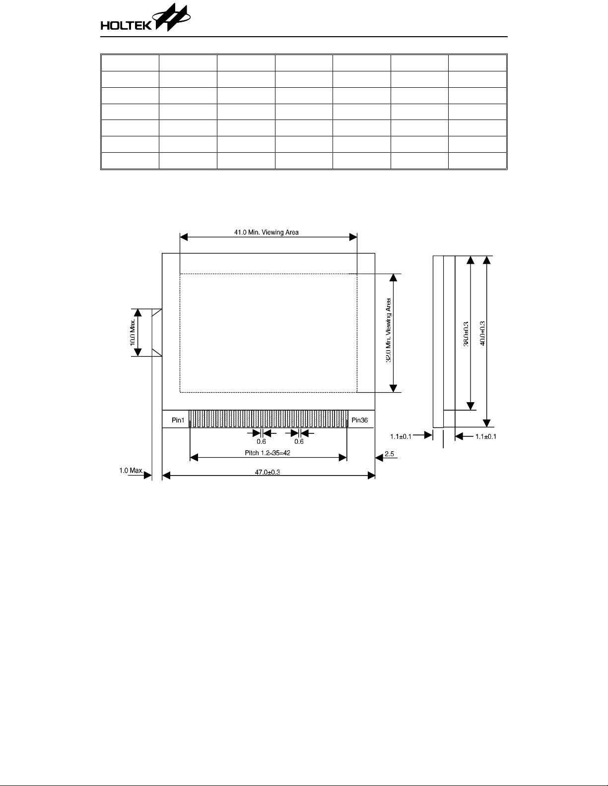
LCD Package Outline
Unit : mm
7 17th Nov ’98

Pad Assignment
HT1136A
Chip size: 2790 × 3000 (µm)
* The IC substrate should be connected to VSS in the PCB layout artwork.
8 17th Nov ’98
2

HT1136A
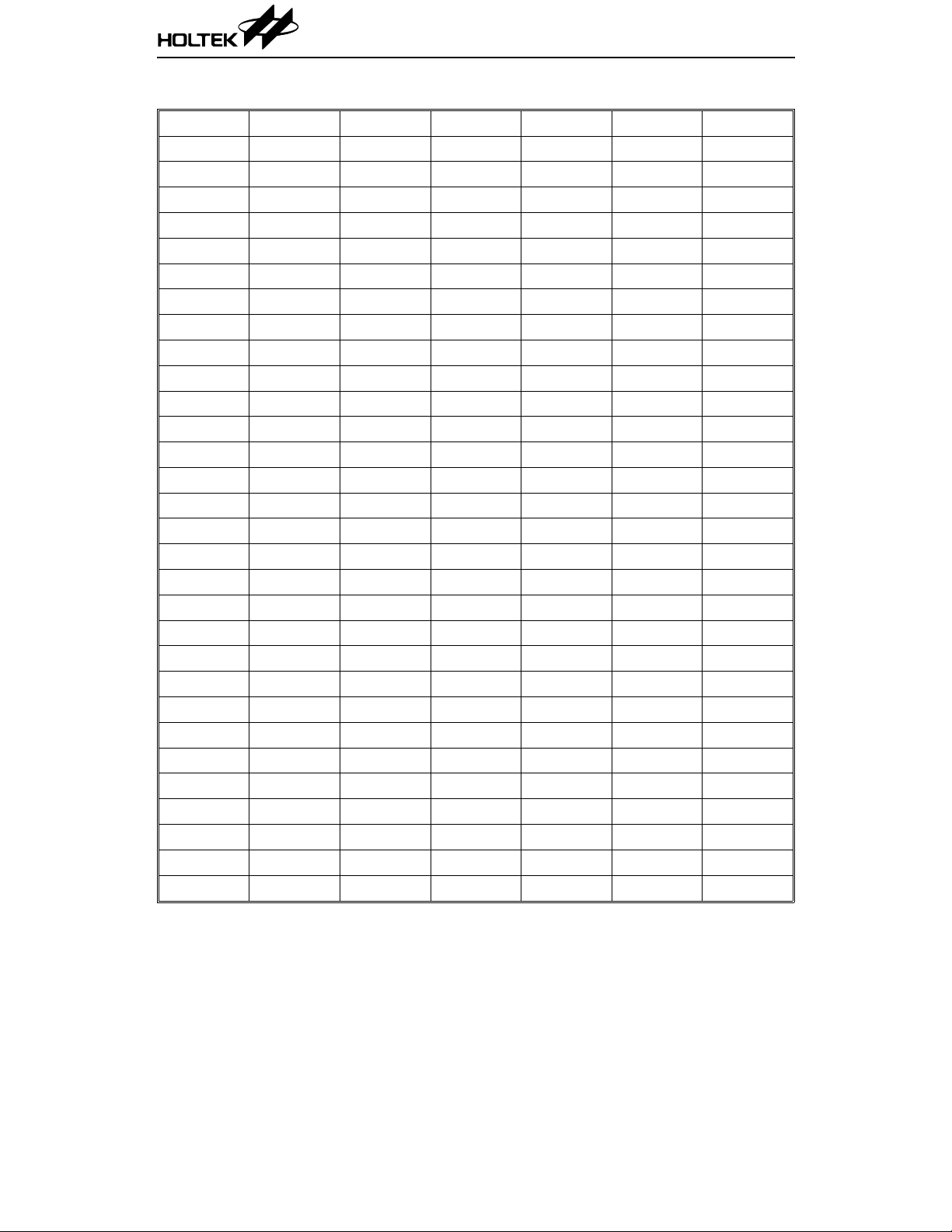
Pad Coordinates Unit: µm
Pad No. X Y Pad No. X Y
1 –1192.10 1305.20 34 1261.10 –1122.30
2 –1192.10 1 169.80 35 1261.10 –979.80
3 –1196.70 1019.80 36 1261.10 –836.30
4 –1261.10 873.70 37 1261.10 –693.80
5 –1261.10 731.20 38 1261.10 –550.30
6 –1261.10 587.70 39 1261.10 –407.80
7 –1261.10 445.20 40 1261.10 –264.30
8 –1261.10 301.70 41 1261.10 –121.80
9 –1261.10 159.20 42 1261.10 21.70
10 –1261.10 15.70 43 1261.10 164.20
11 –1261.10 –126.80 44 1261.10 307.70
12 –1261.10 –270.30 45 1261.10 450.20
13 –1261.10 –412.80 46 1261.10 593.70
14 –1261.10 –556.30 47 1261.10 736.20
15 –1261.10 –698.80 48 1261.10 879.70
16 –1261.10 –842.30 49 1261.10 1022.20
17 –1261.10 –984.80 50 1261.10 1165.70
18 –1261.10 –1128.30 51 1261.10 1311.20
19 –876.70 –1331.40 52 1001.00 1331.40
20 –719.70 –1331.40 53 858.50 1331.40
21 –542.10 –1241.00 54 715.00 1331.40
22 –406.70 –1241.00 55 572.50 1331.40
23 –276.30 –1241.00 56 429.00 1331.40
24 –140.90 –1241.00 57 286.50 1331.40
25 –10.50 –1241.00 58 143.00 1331.40
26 124.90 –1241.00 59 0.50 1331.40
27 284.90 –1331.40 60 –143.00 1331.40
28 427.40 –1331.40 61 –285.50 1331.40
29 570.90 –1331.40 62 –429.00 1331.40
30 713.40 –1331.40 63 –571.50 1331.40
31 856.90 –1331.40 64 –715.00 1331.40
32 999.40 –1331.40 65 –857.50 1331.40
33 1261.10 –1265.80 66 –990.50 1331.40
9 17th Nov ’98
HT1136A
Absolu te Maximu m R a tin g s *
Supply Voltage .......................VDD–0.3V to 5.5V Input Voltage.................VSS–0.3V to VDD+0.3V
Storage Temperature.................–50°C to 125°C Operating Temperature...................0°C to 70°C
*Note: These are stress ra tings on ly. Stresses exceeding the ra nge spe cified under “A bsolute M axi-
mum Ratings” ma y cause substantial damage to the device. Functional operation of this
device at other conditions beyond those listed in the specification is not implied and prolonged
exposure to extreme condition s may affect device reliability.
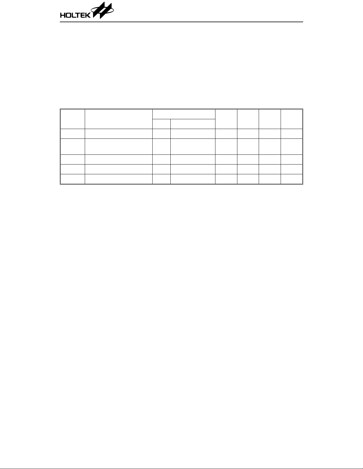
Electrical Characteristics Ta=25°C
Symbol Parameter
V
DD
I
DD
I
STB
V
LCD
f
SYS
Operating Voltage — — 2.4 3 3.3 V
Operating Current 3V
Standby Current 3V No load — 1µ 5µµA
LCD Supply Voltage 3V — — 3 — V
Operating Frequency 3V R=82kΩ — 230 — kHz
Test Conditions
V
DD
Conditions
No load,
f
=230kHz
SYS
Min. Typ. Max. Unit
— 200 330
µA
10 17th Nov ’98
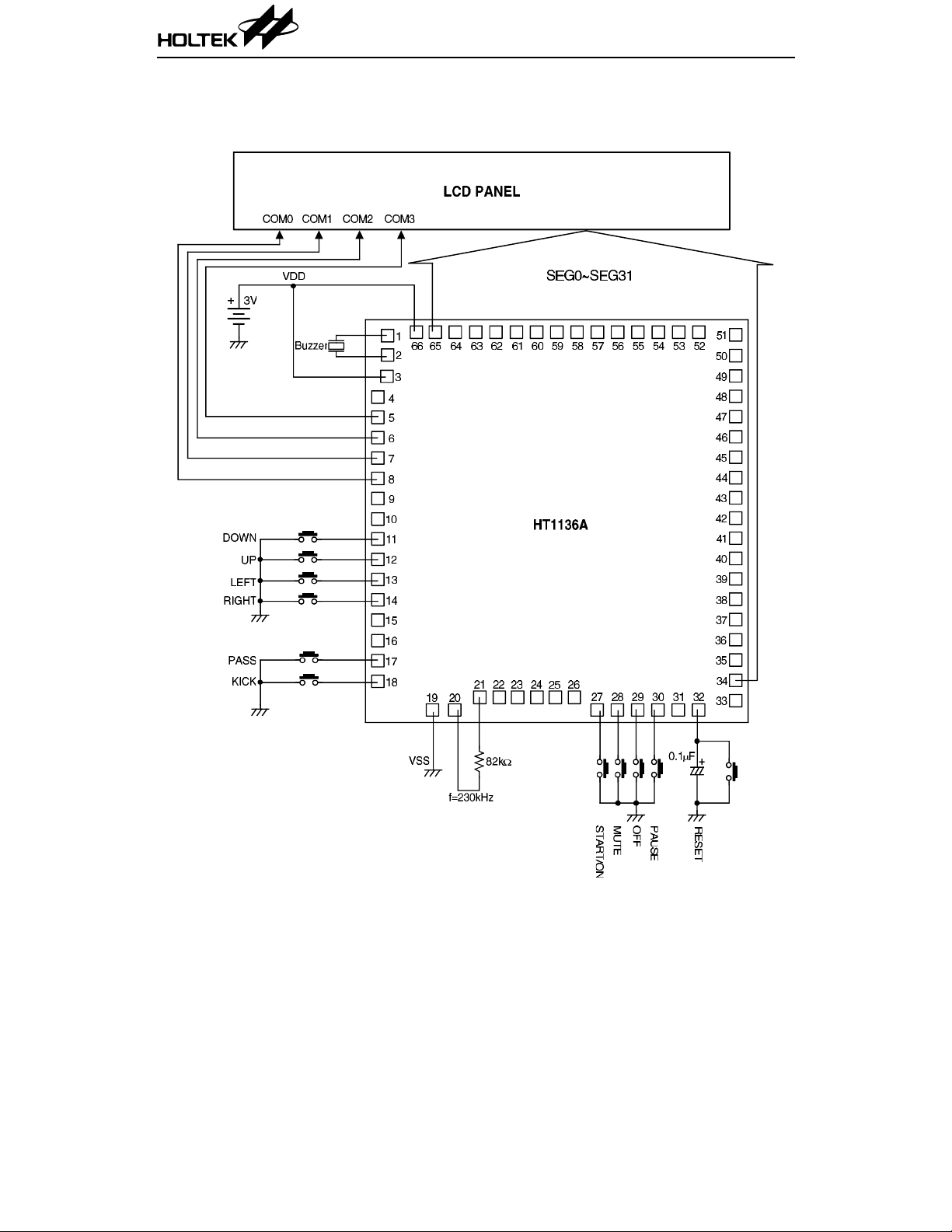
Application Circuits
Buzzer application
HT1136A
Note: The IC substrate should be connected to VSS in the PCB layout artwork.
11 17th Nov ’98
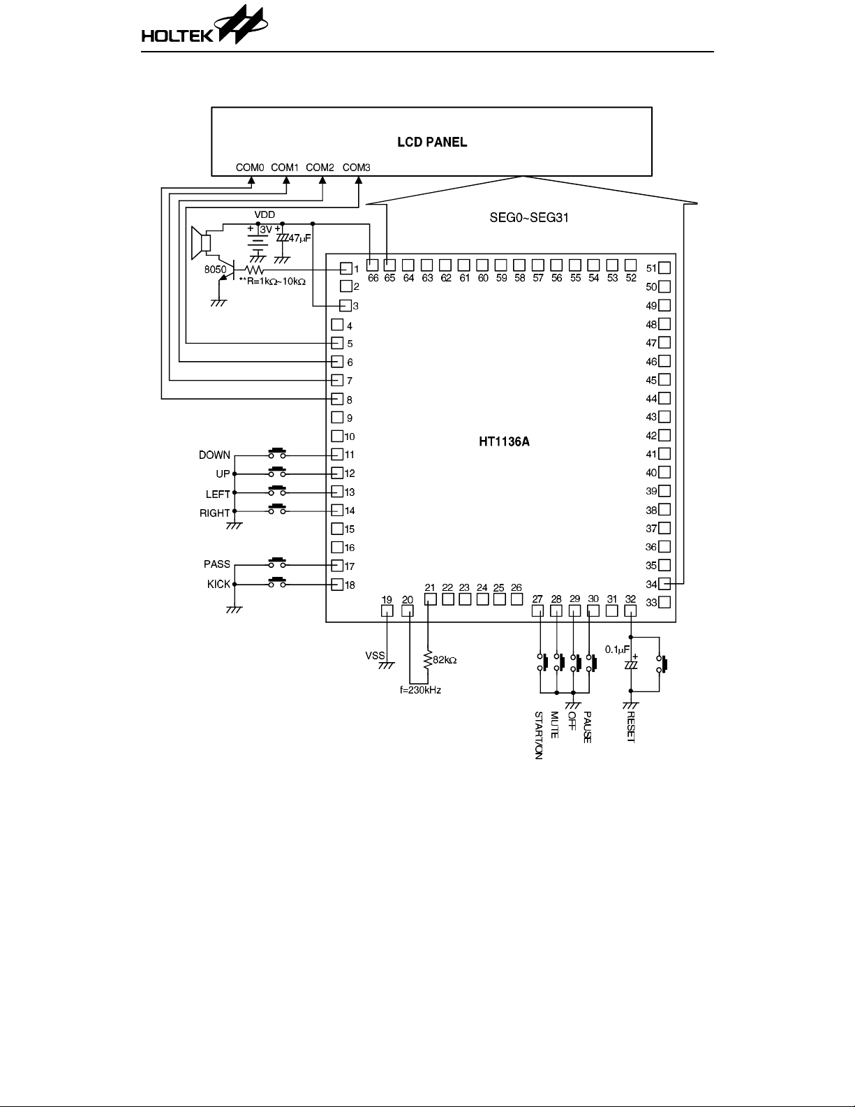
Speaker application
HT1136A
Notes: The IC substrate should be connected to VSS in the PCB layout artwork.
** User can change the volume by changing the resistance 1k
12 17th Nov ’98
Ω~10kΩ.
 Loading...