

Features
•
1/3 bias, 1/4 duty, 32×4 pattern,
3.0V LCD driver
General Description
HT1134A is an LCD Pin Ball game designed by
HOLTEK. It has a built-in sound effect driver to
create vivid resul ts. It is much like a real pin
ball. This game contains five levels. The higher
the level is, the faster is the speed. Wh en the
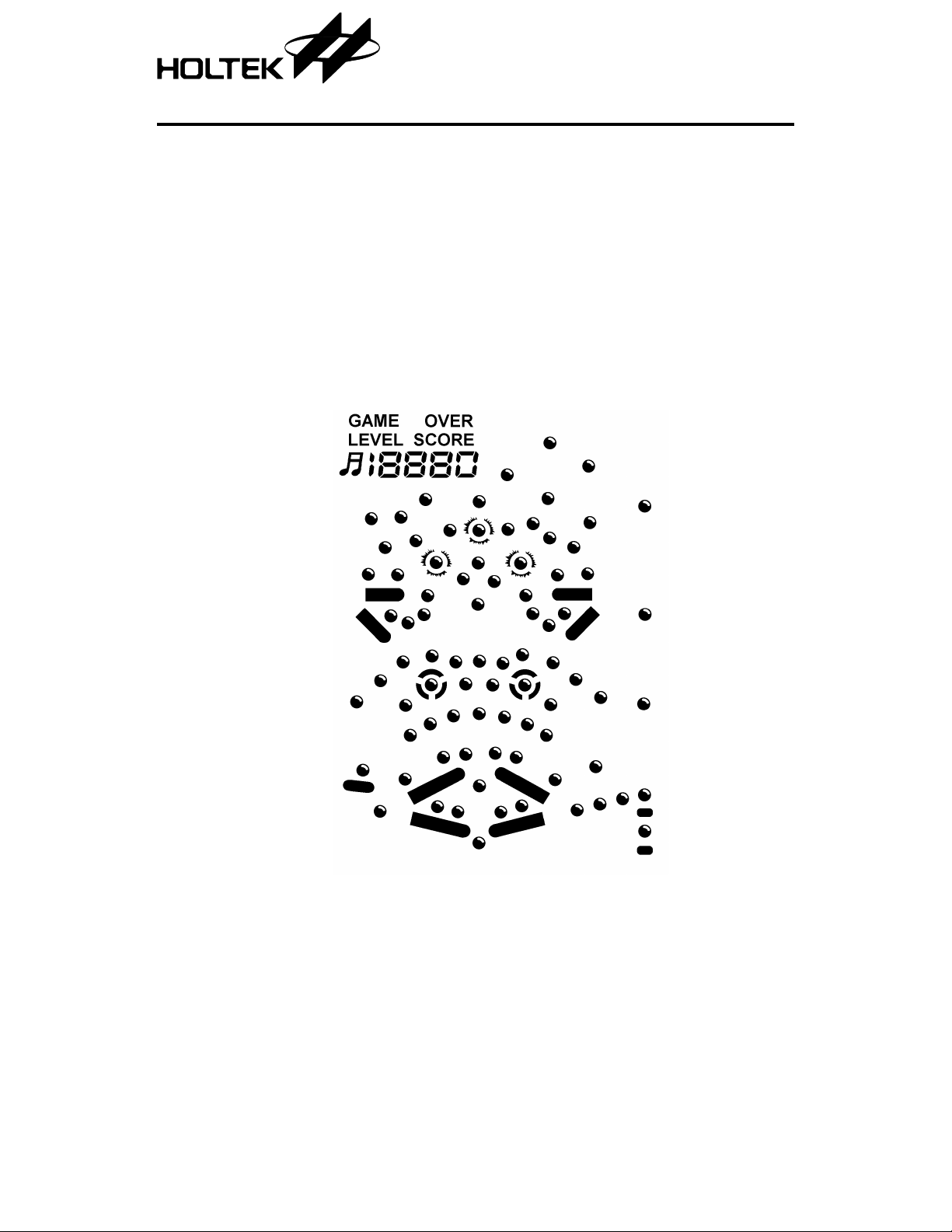
LCD Pattern
HT1134A
Pin Ball LCD Game
•
12 kinds of sound effects
•
RC oscillator
score reaches a certain number, the level goes
up. The highest score is up to 19990. The level
can be set up before the ga me starts. It is not
necessary to start from level 1-1.
1 24th Dec ’98

Functional Description
HT1134A
Key descripti o n
•
RESET
Pressing this key at any ti me resets the sys-
tem back to the starting condition and the
highest score is cleared.
•
PAUSE
Pressing this key any time after power on, can
temporarily stop the game, freeze the screen
and stop the sound effects. Press this key
again, and the game will continue. During the
pause condition, all the other keys have no
effect except OFF and RESET key.
•
OFF
Pressing this key any time after power on,
can clear the screen. Except turning on the
power again, all the other keys are disabled
and the entire system goes into the low power
mode. It is similar with the powe r off condition, however, the highest records are kept.
•
MUTE
This key can turn the sound effects on or off
without disturbing the game. Wh en power is
on, press this key to turn off the sound effects.
Press it again to restore the sound effects.
•
START/ON
When power is off, thi s key is to turn on the
power. When power is on, this key is to restart
the game.
•
LFLIP
Press this key to move up two flips on the left
of the screen. When it is released, the flips are
moved down.
•
RFLIP
At the beginning of the game, this functions as
in serving a ball. Wh en the b all gets into the
activity zone, it becomes a right flip which has
the same function as LFLIP.
Operationa l desc r i p t i o n
There are five levels in thi s game. Each level
has different shifting speed. The higher the
level is, the faster is the speed. When
START/ON key is pressed, the highest score is
shown and the initi al le vel is dis pla yed . P layer
can press RFLIP to select the level . After that,
press START/ON key to start the game. Press
RFLIP to serve the ball, when the ball drops,
depending on its position press LFLIP or RFLIP
to flip the ball and prevent it from droppi ng to
the goal. The strength to serve a ball depends on
the length of time alloted in pressing RFLIP
key . There is a gate at the bottom left side of the
screen. The gate will open or clos e at interva ls.
The ball should be prevented from dropping
down to the gate when it is open. There are only
three balls served in each level. When the score
reaches 3000 or 7000, one ball is relatively
added as bonus. When power is on, or player
has to select a level, or when the game is over, if
the player does not press any key at any one of
the three conditions, then it automatically goes
into free run within one minute. During free
run, if START/ON or OFF key is pressed, then
the game starts, or the power is off. Otherwise,
if the free run lasts about 4 minutes 20 seconds,
the power is automatically turned off. The highest score is lost only when RESET key is
pressed or when the battery is changed.
•
LCD test pattern
At any time, press LFLIP or RFLIP key simul-
taneously with RESET ke y, then release the
RESET key, all the LCD patterns are shown.
When LFLIP or RFLIP key is also release d,
the program goes back to normal.
2 24th Dec ’98

HT1134A
Counting method
•
10 score is counted wh en the ball is touched
once with left or right flip.
•
10 score is counted wh en the ball is touched
once with the three circles. 30 score is counted
if it gets into any one of the circles.
•
30 score i s counted whe n the ball is pa ssing
through the left or the right gate.
•
50 score is counted when the ball gets into the
two circles located between screen.
•
30 score is counted when the ball gets into the
gate at the bottom left.
•
When the ball is served, 10 or 20 or 30 score is
counted depending on the path it takes to get
into the activity zone. The smaller the
strength to serve the ball, the lower is the
score.
Sound effects
There are 12 kinds of sound effects in this game.
•
Power on sound
•
Game start
•
Sound of serving a ball
•
Sound that the ball is touch ed with circle or
right or left flip
•
Sound that the ball gets into the circle
•
Sound that the ball gets into the rotating circle
•
Sound that the ball is shifting
•
Sound that the ball is in the hole
•
Sound that the ball is passing through the
gate
•
Sound that the ball is dropping into the goal
•
Game over sound
•
Sound that the flips flip th e ball
3 24th Dec ’98
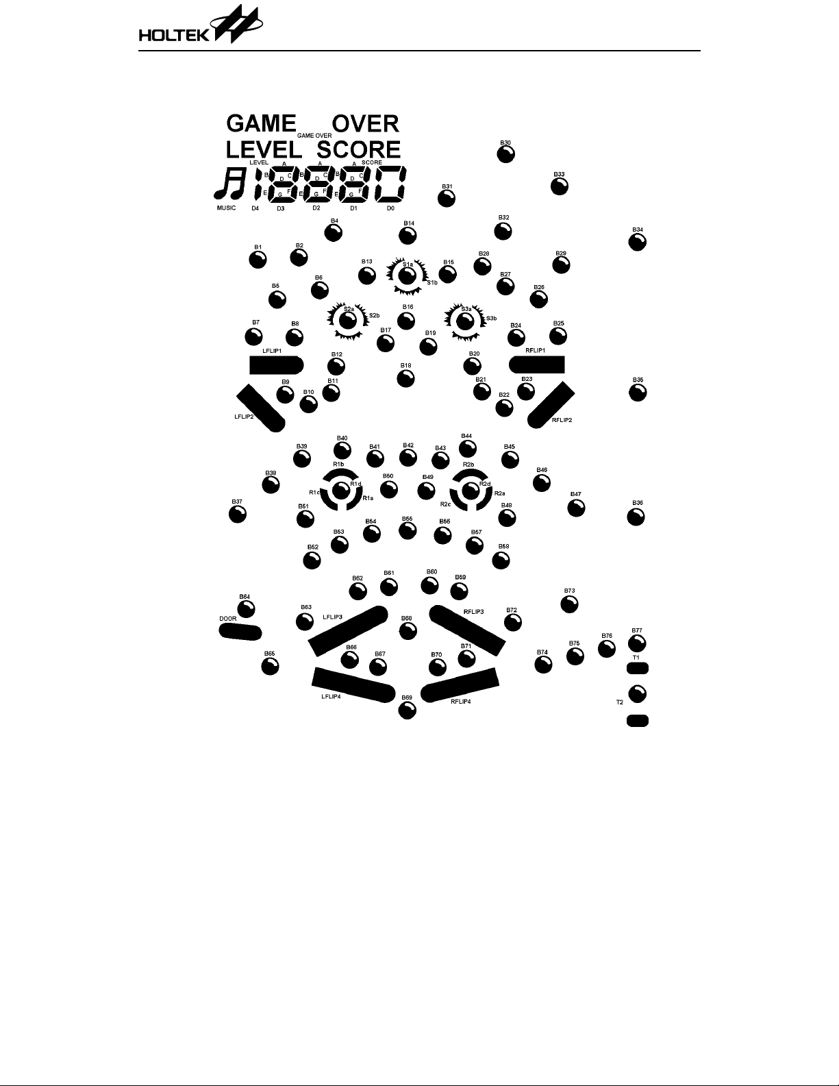
LCD Display Label
HT1134A
4 24th Dec ’98

HT1134A
LCD Pattern Contrast Table
Pad No. Pin No. COM1 COM2 COM3 COM4 SEGMENT
34 1 GAME OVER D3C D3D D3F 1
35 2 D2A D2B D2E D2G 2
36 3 SCORE D2C D2D D2F 3
37 4 D1A D1B D1E D1G 4
38 5 D0 D1C D1D D1F 5
39 6 B14 B4 B2 B1 6
40 7 S1B B13 B6 B5 7
41 8 S1A S2B S2A B8 8
42 9 B16 B17 B12 B7 9
43 10 B19 B18 B11 LFLIP1 10
44 11 B44 B42 B10 B9 11
45 12 B43 B41 B40 LFLIP2 12
46 13 B49 B50 R1B B39 13
47 14 B55 R1A R1D R1C 14
48 15 B60 B54 B51 B38 15
49 16 B59 B62 B53 B37 16
50 17 RFLIP3 B61 B63 B52 17
51 18 B71 B68 LFLIP3 B64 18
52 19 B70 B67 B66 DOOR 19
53 20 RFLIP4 B69 LFLIP4 B65 20
5 21 — — — COM4 COM4
6 22 — — COM3 — COM3
7 23 — COM2 — — COM2
8 24 COM1 — — — COM1
8 25 COM1 — — — COM1
7 26 — COM2 — — COM2
6 27 — — COM3 — COM3
5 28 — — — COM4 COM4
—29— ————
54 30 B76 B77 T1 T2 21
5 24th Dec ’98

HT1134A
Pad No. Pin No. COM1 COM2 COM3 COM4 SEGMENT
55 31 B74 B75 B72 B73 22
56 32 R2C B56 B57 B58 23
—33— ————
57 34 R2D R2A B48 B47 24
—35— ————
58 36 R2B B45 B46 B36 25
—37— ————
—38— ————
—39— ————
59 40 B21 B22 RFLIP2 B35 26
60 41 B20 B23 RFLIP1 B25 27
61 42 S3A B24 B26 B29 28
—43— ————
—44— ————
62 45 S3B B28 B27 B34 29
63 46 B15 B32 B30 B33 30
64 47 B31 LEVEL D4 MUSIC 31
65 48 D3A D3B D3E D3G 32
6 24th Dec ’98

HT1134A
LCD Package Outline Unit : mm
7 24th Dec ’98

Pad Assignment
HT1134A
Chip size: 2970 × 3000 (µm)
* The IC substrate should be connected to VSS in the PCB layout artwork.
8 24th Dec ’98
2

HT1134A
Pad Coordinates
Pad No. X Y Pad No. X Y
1 –1192 .1 0 1305.20 34 1261.10 –1122.30
2 –1192 .10 1169.80 35 1261.10 –979.80
3 –1196 .70 1019.80 36 1261.10 –836.30
4 –1261.10 873.70 37 1261.10 –693.80
5 –1261.10 731.20 38 1261.10 –550.30
6 –1261.10 587.70 39 1261.10 –407.80
7 –1261.10 445.20 40 1261.10 –264.30
8 –1261.10 301.70 41 1261.10 –121.80
9 –1261.10 159.20 42 1261.10 21.70
10 –1261.10 15.70 43 126 1.10 164.20
11 –1261 .1 0 –126.80 44 126 1.10 307.70
12 –1261.10 –270.30 45 1261.10 4 50 .20
13 –1261.10 –412.80 46 1261.10 5 93 .70
14 –1261.10 –556.30 47 1261.10 7 36 .20
15 –1261.10 –698.80 48 1261.10 8 79 .70
16 –1261.10 –842.30 49 1261.10 1022.20
17 –1261.10 –984.80 50 1261.10 1165.70
18 –1261.10 –1128 .3 0 51 1261.10 1311.20
19 –876.70 –1331.40 52 1001.00 1331.40
20 –719.70 –1331.40 53 8 58 .50 1 33 1.40
21 –542.10 –1241.00 54 7 15 .00 1 33 1.40
22 –406.70 –1241.00 55 5 72 .50 1 33 1.40
23 –276.30 –1241.00 56 4 29 .00 1 33 1.40
24 –140.90 –1241.00 57 2 86 .50 1 33 1.40
25 –10.50 –1241.00 58 143.00 1331.40
26 124.90 –1241.00 59 0.50 1331.40
27 284.90 –1331.40 60 –143.00 1331.40
28 427.40 –1331.40 61 –285.50 1331.40
29 570.90 –1331.40 62 –429.00 1331.40
30 713.40 –1331.40 63 –571.50 1331.40
31 856.90 –1331.40 64 –715.00 1331.40
32 999.40 –1331.40 65 –857.50 1331.40
33 1261.10 –1265.80 66 –990.50 1331.40
Unit: µm
9 24th Dec ’98

HT1134A
Absolute Maximum Ratings*
Supply Voltage...... ........................–0.3V to 5.5V
Input Voltage..................V
–0.3V to VDD+0.3V
SS
*Note: These are stress ra tings on ly. Stresses exceeding the range specified under “Absolute Maxi-
mum Ratings” may cause substantial damage to the device. Functional operation of this
device at other conditions beyond those listed in the specification is not implied and prolonged
exposure to extreme condition s may affect device reliability.
Electrical Characteristics Ta=25°C
Storage Temperature.................–50
Operating Temperature...................0
°C to 125°C
°C to 70°C
Symbol Parameter
V
I
I
V
f
DD
DD
STB
LCD
SYS
Operating Voltage — — 2.4 3 3.3 V
Operating Current 3V
Standby Current 3V No load — 1 5
LCD Supply Voltage 3V — — 3 — V
Operating Freq ue nc y 3V
Test Condition
V
DD
Condition
No load,
f
=256kHz
SYS
R=75k
Min. Typ. Max. Unit
— 250 500
µA
µA
Ω
—256—kHz
10 24th Dec ’98

Application Circuits
Buzzer application
HT1134A
Note: The IC substrate should be connected to VSS in the PCB layout artwork.
11 24th Dec ’98

Speaker application
HT1134A
Notes: The IC substrate should be connected to VSS in the PCB layout artwork.
** User can change the volume by changing the resistance 1k
12 24th Dec ’98
Ω~10kΩ.
 Loading...