

Page 1

MODEL HGC SERIES GAS CONVEYOR
OVENS
MODELS
HGC3018 ML-126180
HGC4018 ML-126181
HGC3624 ML-126182
HGC3632 ML-126183
HGC4824 ML-126184
HGC4832 ML-126185
HGC6024 ML-126186
HGC6032 ML-126187
701 S. RIDGE AVENUE
TROY, OHIO 45374-0001
FORM 34069 (6-98)
Page 2

IMPORTANT FOR YOUR SAFETY
THIS MANUAL HAS BEEN PREPARED FOR PERSONNEL QUALIFIED TO INSTALL GAS
EQUIPMENT, WHO SHOULD PERFORM THE INITIAL FIELD START-UP AND
ADJUSTMENTS OF THE EQUIPMENT COVERED BY THIS MANUAL.
POST IN A PROMINENT LOCATION THE INSTRUCTIONS TO BE FOLLOWED IN THE
EVENT THE SMELL OF GAS IS DETECTED. THIS INFORMATION CAN BE OBTAINED
FROM THE LOCAL GAS SUPPLIER.
IMPORTANT
IN THE EVENT A GAS ODOR IS DETECTED, SHUT
DOWN UNITS AT MAIN SHUTOFF VALVE AND
CONTACT THE LOCAL GAS COMPANY OR GAS
SUPPLIER FOR SERVICE.
FOR YOUR SAFETY
DO NOT STORE OR USE GASOLINE OR OTHER
FLAMMABLE VAPORS OR LIQUIDS IN THE
VICINITY OF THIS OR ANY OTHER APPLIANCE.
WARNING
IMPROPER INSTALLATION, ADJUSTMENT,
ALTERATION, SERVICE OR MAINTENANCE CAN
CAUSE PROPERTY DAMAGE, INJURY OR DEATH.
READ THE INSTALLATION, OPERATING AND
MAINTENANCE INSTRUCTIONS THOROUGHLY
BEFORE INSTALLING OR SERVICING THIS
EQUIPMENT.
IN THE EVENT OF A POWER FAILURE, DO NOT
ATTEMPT TO OPERATE THIS DEVICE.
© HOBART CORPORATION, 1998
— 2 —
Page 3

TABLE OF CONTENTS
GENERAL. . . . . . . . . . . . . . . . . . . . . . . . . . . . . . . . . . . . . . . . . . . . . . . . . . . . . . . . . . . . . . . . . . . . . . 4
INSTALLATION . . . . . . . . . . . . . . . . . . . . . . . . . . . . . . . . . . . . . . . . . . . . . . . . . . . . . . . . . . . . . . . . . 4
Unpacking . . . . . . . . . . . . . . . . . . . . . . . . . . . . . . . . . . . . . . . . . . . . . . . . . . . . . . . . . . . . . . . . 4
Location . . . . . . . . . . . . . . . . . . . . . . . . . . . . . . . . . . . . . . . . . . . . . . . . . . . . . . . . . . . . . . . . . 5
Installation Codes and Standards . . . . . . . . . . . . . . . . . . . . . . . . . . . . . . . . . . . . . . . . . . . . . 6
Assembly . . . . . . . . . . . . . . . . . . . . . . . . . . . . . . . . . . . . . . . . . . . . . . . . . . . . . . . . . . . . . . . . 7
Leveling . . . . . . . . . . . . . . . . . . . . . . . . . . . . . . . . . . . . . . . . . . . . . . . . . . . . . . . . . . . . . . . . . 8
Gas Connections . . . . . . . . . . . . . . . . . . . . . . . . . . . . . . . . . . . . . . . . . . . . . . . . . . . . . . . . . . 8
Testing the Gas Supply System . . . . . . . . . . . . . . . . . . . . . . . . . . . . . . . . . . . . . . . . . . . . . . 8
Electrical Connections . . . . . . . . . . . . . . . . . . . . . . . . . . . . . . . . . . . . . . . . . . . . . . . . . . . . . . 9
OPERATION . . . . . . . . . . . . . . . . . . . . . . . . . . . . . . . . . . . . . . . . . . . . . . . . . . . . . . . . . . . . . . . . . . 10
Controls . . . . . . . . . . . . . . . . . . . . . . . . . . . . . . . . . . . . . . . . . . . . . . . . . . . . . . . . . . . . . . . . 10
Alternate Controls . . . . . . . . . . . . . . . . . . . . . . . . . . . . . . . . . . . . . . . . . . . . . . . . . . . . . . . . 12
Before First Use . . . . . . . . . . . . . . . . . . . . . . . . . . . . . . . . . . . . . . . . . . . . . . . . . . . . . . . . . . 14
Lighting Instructions . . . . . . . . . . . . . . . . . . . . . . . . . . . . . . . . . . . . . . . . . . . . . . . . . . . . . . . 14
Using the Oven. . . . . . . . . . . . . . . . . . . . . . . . . . . . . . . . . . . . . . . . . . . . . . . . . . . . . . . . . . . 15
Cleaning . . . . . . . . . . . . . . . . . . . . . . . . . . . . . . . . . . . . . . . . . . . . . . . . . . . . . . . . . . . . . . . . 17
Conveyor Belt Assembling and Disassembling . . . . . . . . . . . . . . . . . . . . . . . . . . . . . . . . . 21
Cooking Chart . . . . . . . . . . . . . . . . . . . . . . . . . . . . . . . . . . . . . . . . . . . . . . . . . . . . . . . . . . . 22
MAINTENANCE . . . . . . . . . . . . . . . . . . . . . . . . . . . . . . . . . . . . . . . . . . . . . . . . . . . . . . . . . . . . . . . . 23
Inspection . . . . . . . . . . . . . . . . . . . . . . . . . . . . . . . . . . . . . . . . . . . . . . . . . . . . . . . . . . . . . . . 23
Service and Parts Information . . . . . . . . . . . . . . . . . . . . . . . . . . . . . . . . . . . . . . . . . . . . . . . 23
TROUBLESHOOTING GUIDE . . . . . . . . . . . . . . . . . . . . . . . . . . . . . . . . . . . . . . . . . . . . . . . . . . . . 24
— 3 —
Page 4

Installation, Operation and Care of
MODEL HGC SERIES GAS CONVEYOR OVENS
PLEASE KEEP THIS MANUAL FOR FUTURE USE
GENERAL
Hobart ovens are produced with quality workmanship and material. Proper installation, usage and
maintenance of your oven will result in many years of satisfactory performance.
It is suggested that you thoroughly read this entire manual and carefully follow all of the instructions
provided.
INSTALLATION
Before installing, verify that the electrical service and type of gas supply (natural or propane) agree with
the specifications on the rating plate located on the right front side panel. If the supply and equipment
requirements do not agree, do not proceed with the installation. Contact your Hobart service
representative immediately.
UNPACKING
This oven was inspected before leaving the factory. The transportation company assumes full
responsibility for safe delivery upon acceptance of the shipment. Immediately after unpacking, check
for possible shipping damage. If the oven is found to be damaged, save the packaging material and
contact the carrier within 15 days of delivery.
1. Tilt the oven on its back side.
2. Place the oven on a four-wheel dolly.
3. Move oven to its installation position.
4. Remove the oven from the dolly and place on two pieces of 2 x 4 wood.
5. Carefully unpack the oven.
Do not use the door or the handle to lift the oven.
— 4 —
Page 5

LOCATION
When the crate is turned on its side, the oven will pass through a 34" (86 cm) door opening (or 30" [76 cm]
opening without the crate). Verify that the doors and access routes into the kitchen area will permit
clearance.
The equipment area must be kept free and clear of combustible substances.
When installed, minimum clearance from combustible and non-combustible construction must be 2.5"
(63.5 mm) at the sides and 2.5" (63.5 mm) at the rear.
The installation location must allow adequate clearances for servicing and proper operation.
A minimum front clearance of 36" (914.4 mm) is required.
Do not obstruct the flow of combustion and ventilation air.
• Adequate clearance for air openings into the oven must be provided.
• Make sure there is an adequate supply of air in the room to replace air taken out by the ventilating
system.
• The ventilation hood should extend 6" (152 mm) minimum past the oven on the front, back, and
each side of the conveyor belt.
Information on the construction and installation of ventilating hoods may be obtained from the standard
for "Vapor Removal from Cooking Equipment," NFPA No. 96 (latest edition), available from the
National Fire Protection Association, Batterymarch Park, Quincy, MA 02269.
Exhaust: Approximately 2000 CFM required for double stacked ovens.
Approximately 1500 CFM required for single oven.
Make-up air should be 65% to 80% of the exhaust air rating.
Do not permit fans to blow directly at the oven.
• Wherever possible, avoid open windows next to the oven.
• Avoid wall-type fans which create air cross currents within the room.
— 5 —
Page 6

INSTALLATION CODES AND STANDARDS
The oven must be installed in accordance with:
In the United States of America:
1. State and local codes.
2. National Fuel Gas Code, ANSI-Z223.1 (latest edition). Copies may be obtained from The American
Gas Association, Inc., 1515 Wilson Blvd., Arlington, VA 22209.
3. National Electrical Code, ANSI/NFPA-70 (latest edition). Copies may be obtained from The
National Fire Protection Association, Batterymarch Park, Quincy, MA 02269.
In Canada:
1. Local codes.
2. CAN/CGA-B149.1 Natural Gas Installation Code (latest edition).
3. CAN/CGA-B149.2 Propane Installation Code (latest edition), available from the Canadian Gas
Association, 178 Rexdale Blvd., Etobicoke, Ontario, Canada M9W 1R3.
4. Canadian Electrical Code, CSA C22.2 No. 3 (latest edition). Copies may be obtained from The
Canadian Standard Association, 178 Rexdale Blvd., Etobicoke, Ontario, Canada M9W 1R3.
— 6 —
Page 7
ASSEMBLY
Ovens Mounted on Legs or Feet
To service the oven when mounted on legs or feet, a minimum clearance of 18" (457 mm) from service
compartment is required.
Ovens Mounted on Casters
NOTICE: In order to be able to service this appliance, it must be installed with the casters supplied,
a connector complying with ANSI Z21.69 or CAN/CGA-6.16, and a quick-disconnect device complying
with ANSI Z21.41 or CAN1-6.9. It must also be installed with restraining means to guard against
transmission of strain to the connector, as specified in the appliance manufacturer's installation
instructions.
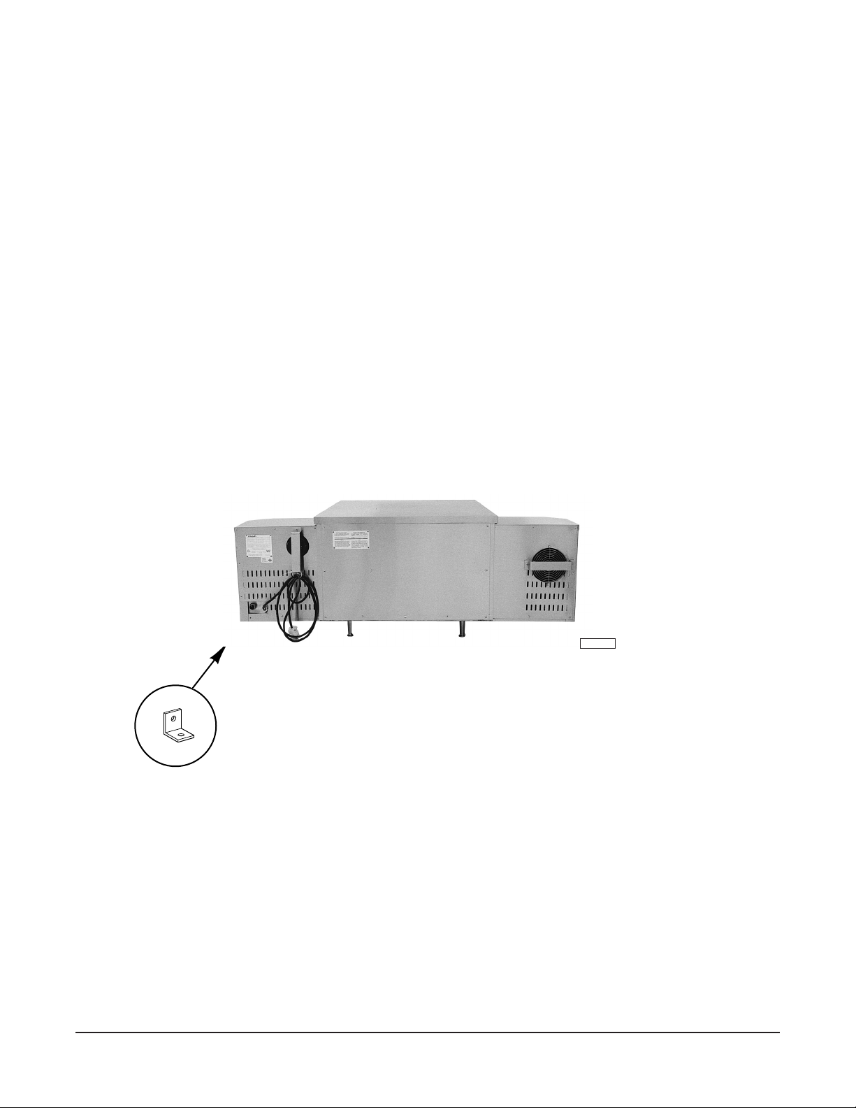
Attach the restraining device at the rear of the oven (Fig. 1).
If disconnection of the restraint is necessary:
1. Turn off the gas supply before disconnection.
2. Reconnect restraint before turning on the gas supply.
3. Return the oven to its installation position.
CONNECT GAS
LINE STRAIN
RELIEF HERE
Fig. 1
Installing Basic Oven
1. Attach the front legs by screwing them into the bottom of the oven.
2. Tilt oven forward resting it on the front legs.
3. Lift the oven from the rear.
4. Once the oven is lifted, attach the back legs.
5. Place the oven in its operating position.
PL-41122
— 7 —
Page 8

Installing Stacked Ovens
After basic oven is installed:
• Lift the top oven and place it on top of the bottom oven.
• No fasteners are required; the weight of the oven will keep it in place.
LEVELING
Casters for this oven are of the non-adjustable type. For best results, oven should be installed on a
level floor.
GAS CONNECTIONS
Gas supply connections and any pipe joint compound must be resistant to the action of propane gases.
3
Location of the
⁄4" gas inlet is at the back of the oven on the lower right side.
Codes require that a gas shutoff valve (available from Hobart) must be installed in the gas line ahead
of the oven.
Connect gas supply. Make sure the pipes are clean and free of obstructions.
The ovens are equipped with fixed burner orifices which coincide with installation elevation.
Natural gas and propane gas are preset at the factory for proper operation. Store line pressures are
preset for 7" W.C. (Water Column) (1.75 kPa) for natural gas and 11" W.C. (2.75 kPa) for propane gas.
WARNING: PRIOR TO LIGHTING, CHECK ALL JOINTS IN THE GAS SUPPLY LINE FOR LEAKS.
USE SOAP AND WATER SOLUTION. DO NOT USE AN OPEN FLAME.
After piping has been checked for leaks, all piping receiving gas should be fully purged to remove air.
TESTING THE GAS SUPPLY SYSTEM
• When gas supply pressure exceeds
1
/2 psig (3.45 kPa), the oven and its individual shutoff valve
must be disconnected from the gas supply piping system.
• When gas supply pressure is
1
/2 psig (3.45 kPa) or less, the oven should be isolated from the gas
supply system by closing its individual manual shutoff valve.
— 8 —
Page 9

ELECTRICAL CONNECTIONS
WARNING: ELECTRICAL AND GROUNDING CONNECTIONS MUST COMPLY WITH THE
APPLICABLE PORTIONS OF THE NATIONAL ELECTRICAL CODE AND/OR OTHER LOCAL
ELECTRICAL CODES.
WARNING: APPLIANCES EQUIPPED WITH A FLEXIBLE ELECTRIC SUPPLY CORD ARE
PROVIDED
WITH A THREE-PRONG GROUNDING PLUG. IT IS IMPERATIVE THAT THIS PLUG BE
CONNECTED INTO A PROPERLY GROUNDED THREE-PRONG RECEPTACLE. IF THE
RECEPTACLE IS NOT THE PROPER GROUNDING TYPE, CONTACT AN ELECTRICIAN. DO NOT
REMOVE THE GROUNDING PRONG FROM THIS PLUG.
The oven is equipped with a power supply cord for service at 120 volts and 20 amps. A 20 amp
receptacle and service is required for proper operation of the oven.
Do not connect the oven to electrical supply until after gas connections have been made.
— 9 —
Page 10

OPERATION
WARNING: THE OVEN AND ITS PARTS ARE HOT. BE VERY CAREFUL WHEN OPERATING,
CLEANING OR SERVICING THE OVEN.
CONTROLS (Fig's. 2 and 3)
TEMPERATURE DISPLAY
READ SET POINT BUTTON
TIME RANGE
SWITCH
POWER SWITCH
LOAD INDICATOR LIGHT
TIME DISPLAY
BELT SWITCH
TIME KNOB
PL-41154-1
Fig. 2
CYCLE TIME
MAN. RESET PROP. BAND
SET POINT
DOOR FLAP
PL-41155-1
Fig. 3
— 10 —
Page 11

Temperature Display — Displays actual oven cavity temperature during cooking cycle.
Read Set Point Button — Push to display set temperature.
Load Indicator Light — When lit, indicates that the heat is being provided to the oven.
Time Display — Displays actual cooking time in minutes and tenths of minutes.
Time Range Switch — Use to set cook time range from 2 to 8 minutes, 8 to 15 minutes, or 15
to 20 minutes. Switch must be on cook time range desired in order to
change belt speed.
Belt Switch — Press switch to ON to start the conveyor belt; press to OFF to stop the
conveyor belt.
Power Switch — Press to ON to start the oven; press to OFF to stop the oven. When
the power switch is pushed to ON, ignition occurs automatically.
Time Knob — After the Time Range Switch has been set to the desired time range,
turn the knob clockwise to increase the cook time or counterclockwise
to decrease the cook time until it reaches the time desired on the time
display.
Cycle Time — This is a service control only. Do not touch this control.
Man. Reset — This is a service control only. Do not touch this control.
Set Point — Set point adjustment control.
1. Locate the Set Point knob behind the doorflap to adjust the set
point.
2. Press the Read Set Point button so that the set point is displayed,
and at the same time, turn the Set Point knob until the desired set
point temperature appears in the digital display.
3. Release the Read Set Point button.
4. Do not make any other adjustments to this control.
Prop. Band — This is a service control only. Do not touch this control.
— 11 —
Page 12

ALTERNATE CONTROLS (Fig. 4)
SET POINT
TEMPERATURE DISPLAY
SET POINT
INDICATOR
LIGHT
SET POINT ARROWS
TIME DISPLAY
TIME RANGE
SWITCH
POWER SWITCH
CONTROL CIRCUIT FUSE
BELT SWITCH
TIME KNOB
DRIVE MOTOR FUSES
PL-41156-1
Fig. 4
— 12 —
Page 13

Temperature Display — Displays actual oven cavity temperature during cooking cycle.
Set Point — Press to display set temperature.
Set Point Arrows — 1. Press the Set Point button so that the set point is displayed, and
at the same time, press the Set Point Arrows up or down until the
desired set point temperature appears in the digital display.
2. Release the Set Point button. The actual oven cavity temperature
will display.
Set Point Indicator Light — When lit, indicates that the heat is being provided to the oven. When
set point is reached, light will go off.
Time Display — Displays actual cooking time in minutes and tenths of minutes.
Time Range Switch — Use to set cook time range from 2 to 8 minutes, 8 to 15 minutes, or 15
to 20 minutes. Switch must be on cook time range desired in order to
change belt speed.
Belt Switch — Press switch to ON to start the conveyor belt; press to OFF to stop the
conveyor belt.
Power Switch — Press to ON to start the oven; press to OFF to stop the oven. When
the power switch is pressed to ON, ignition occurs automatically.
Time Knob — After the Time Range Switch has been set to the desired time range,
turn the knob clockwise to increase the cook time or counterclockwise
to decrease the cook time until it reaches the time desired on the time
display.
Control Circuit Fuse — 25 Amp. / 250V. Time delay.
Drive Motor Fuses — 375 ma / 250V.
— 13 —
Page 14

BEFORE FIRST USE
1. Clean the protective metal oils from all surfaces of the oven.
2. Use a non-corrosive, grease dissolving commercial cleaner. Follow manufacturer's directions.
3. Rinse thoroughly with a clean damp cloth and wipe dry with a soft clean cloth.
• DO NOT hose down the oven.
• Do not use this oven if its controls have been wet. If the controls are wet, contact your Hobart
servicer.
LIGHTING INSTRUCTIONS
Turning the Oven On
The burner control is a solid state device that automatically ignites and monitors the pilot flame.
To turn the oven on:
1. Turn the gas combination valve (Fig. 5) to ON.
2. Push the Power Switch to ON.
3. Set the oven temperature to desired temperature.
GAS COMBINATION
CONTROL VALVE
Fig. 5
PL-41125-1
If the burner fails to light within 90 seconds:
• The burner control will shut off the gas combination valve and will lock out.
• To reset the burner control for restart, press the Power Switch to OFF and then to ON.
If the burner still fails to light:
• Turn the oven off.
• Wait 5 minutes before restarting.
If lockout occurs again, contact your local Hobart authorized servicer.
Turning the Oven Off
Turn Power Switch to OFF.
— 14 —
Page 15

Extended Shutdown
1. Turn Power Switch to OFF.
2. Turn gas combination valve to OFF.
3. Turn main gas shutoff valve to OFF.
USING THE OVEN
1. Turn the main power switch ON.
• The oven will begin operating at the factory set temperature of 525°F (273°C).
• The actual oven cavity temperature will appear in the temperature display.
• The Load Indicator Light will indicate if the heat is on.
2. Press and hold the Read Set Point or Set Point button to read the temperature set point.
• The set point will appear in the temperature display.
• To reset the set temperature, see Set Point or Set Point Arrows in the CONTROLS section.
If the conveyor belt stalls:
• The time display will indicate "O.L."
• The belt will automatically stop.
a. Remove the blockage.
b. Move the Belt Switch up and down to reset the control.
• The time should be indicated on the display again.
• The drive motor should restart.
A baffle (Fig. 6) is located on each end of the oven.
• It can be adjusted higher or lower to accommodate the height of the product being cooked.
• To raise or lower the baffles:
1. Loosen the two thumb screws (Fig. 6) - use insulated gloves.
2. Readjust baffle height.
3. Retighten the two thumb screws.
BAFFLE
THUMB SCREWS
(PL-41126-1)
PL-41126-1
Fig. 6
— 15 —
Page 16

Loading and Unloading the Oven
1. Place product in utensils (if required).
2. Set utensils or products on the entrance end of the belt; not in the oven tunnel.
3. Remove utensils or products from the oven after they completely clear the oven tunnel.
Air Distribution Panels
The oven is equipped with a top and a bottom air distribution panel.
• These panels regulate the quantity of air on the top and bottom of the product that is being cooked.
• They have been adjusted at the factory for proper baking performance.
• Some products may need additional panel adjustments. This should be done by a Hobart
authorized servicer.
— 16 —
Page 17

CLEANING
WARNING: DISCONNECT ELECTRICAL POWER SUPPLY BEFORE CLEANING.
Daily
Clean the outside of the oven daily by wiping with a clean damp cloth.
• Avoid using abrasive powders or pads; these cleaners may damage the finish.
Clean right-hand and left-hand crumb trays (Fig. 7).
1. Remove and wash in a sink as you would any normal utensil.
2. Replace crumb trays.
Clean center crumb tray (Fig. 7).
1. Remove the front panel.
a. Grasp each side of the door handle and lift up.
b. Swing the bottom of the front panel out.
c. Lower panel and pull away.
2. Loosen the conveyor belt (see Conveyor Belt Removal in this manual) and brush away the
crumbs under the belt.
3. Remove crumb tray.
4. Wash in a sink as you would any normal utensil.
5. Replace the tray and the front panel by reversing the procedure.
CRUMB TRAYS
PL-41127-1
Fig. 7
— 17 —
Page 18

Conveyor
To maintain proper belt tension, adjust the conveyor belt to remove any slack.
1. Locate the two adjustment screws (Fig. 8) on the right hand end (facing machine) of the
conveyor assembly.
2. Loosen the nuts on the inside of the conveyor rack and turn the adjusting screws clockwise to
increase belt tension. Be sure to adjust both screws an equal amount.
3. Retighten the nuts on the inside of the conveyor rack.
If the conveyor belt adjustment is at its maximum and the belt is still slack, remove one link from
the belt.
1. Locate the conveyor belt splicing strand and remove it as shown in the
ASSEMBLING AND
DISASSEMBLING (Fig. 12).
CONVEYOR BELT
2. Remove one conveyor link and set the tension screws at their minimum by turning them
counterclockwise. Adjust both screws an equal amount.
3. Reinstall the splicing strand as shown in the
CONVEYOR BELT ASSEMBLING AND
DISASSEMBLING (Fig. 12), and readjust the belt tensions with the adjusting screws.
Two ways to remove the conveyor for cleaning:
1. Conveyor Belt Removal
a. Loosen belt tension screws at the end of the belt track (Fig. 8).
b. Locate the wide end-hooks of the splicing strands where the belt should be disconnected.
c.
Remove splicing strands by following the directions shown in CONVEYOR BELT
ASSEMBLING AND
DISASSEMBLING in this manual.
d. Reverse this procedure to replace belt.
BELT TENSION SCREWS
Fig. 8
— 18 —
PL-41128-1
Page 19

2. Conveyor Assembly Removal
a. Remove conveyor crumb trays (see Fig. 7).
b. Remove cover where conveyor shaft enters the left-hand control box (Fig. 9).
REMOVE COVER
PL-41129-1
Fig. 9
c. Lift up the drive end of the conveyor assembly and slide the conveyor assembly into the
oven tunnel to remove the tension on the drive chain.
d. Slip the drive chain off the conveyor drive sprocket (Fig. 10).
Fig. 10
— 19 —
PL-41130
Page 20

e. Pull the entire conveyor assembly from the oven (Fig. 11).
Fig. 11
f. Take conveyor assembly to cleaning area.
g. Reverse this procedure to replace conveyor assembly.
PL-41131
Weekly
CAUTION: Intake fans and slots on the back of the oven and control box must be cleaned
weekly. Any obstructions may cause motor damage.
Use a long bristle brush to clean these areas.
— 20 —
Page 21

CONVEYOR BELT ASSEMBLING AND DISASSEMBLING (Fig. 12)
Install the conveyor belt so that it always runs in
the direction indicated by this arrow — the closed
end of the loop toward the direction of travel.
The arrows in the belt illustrate the movement of
the splicing strand between steps.
When bending the splicing strand, try to limit
bending to straight portions of the strand rather
than in the "Z" bend area.
1
2
3
Splice one side completely before starting the
other side.
After completely splicing the belt, it is advisable to
go along the width of the belt straightening the
spliced-in strand.
Depending upon the width of the belt, there might
be one, two, or three splicing strands.
4
5
6
7
— 21 —
PL-52997
Fig. 12
Page 22

COOKING CHART
The times and temperatures shown in this chart are suggested only. Experiment with your food
products to determine the cooking temperatures and times that give you the best results.
TYPE OF APPROX. TIME TEMP.
FOOD PRODUCT (IN MIN.) (°F) / (°C)
ITALIAN Pizza (par baked dough) 4 to 4.5 510 / 265
Pizza (fresh dough) 5.5 to 6.5 510 / 265
Pizza (thick pan type) 7.5 to 8.5 510 / 165
Calzone (fresh dough) 5 to 6 510 / 265
Pastas (precooked to gratin) 5 to 6 510 / 265
BREADS & SUBS Garlic Bread 2.5 to 3.5 510 / 265
Bread Sticks 2.5 to 3.5 510 / 265
Submarine Sandwiches 2.5 to 3.5 510 / 265
BAKERY Dinner Rolls (par baked) 4 to 4.5 390 / 199
Dinner Rolls (fresh) 7.5 to 8.5 390 / 199
Bagels (fresh) 12 to 13 390 / 199
Croissants (par baked) 4 to 4.5 390 / 199
Croissants (fresh) 9 to 10 390 / 199
Muffins (fresh) 12 to 13 390 / 199
Biscuits and Cookies (fresh) 4.5 to 6.5 390 / 199
MEAT & POULTRY Chicken Wings (precooked) 5.5 to 6.5 510 / 265
Chicken Wings (fresh) 18 to 20 390 / 199
Chicken Breasts (boneless) 5.5 to 6.5 510 / 265
B.B.Q. Ribs (fresh) 18 to 20 390 / 199
Hamburger Patties (fresh) 5.5 to 6.5 510 / 265
FISH & SEAFOOD Shrimp (fresh) 4.5 to 5.5 510 / 265
Fish Filets (fresh) 6.5 to 7.5 510 / 265
Tuna Steak (fresh) 8.5 to 9.5 510 / 265
Salmon Steak (fresh) 6 to 7.5 510 / 265
MEXICAN Burritos and Enchiladas 2.5 to 3.5 475 / 246
Nachos Assorted Styles 2.5 to 3.5 475 / 246
EGGS Souffles and Omelettes 5.5 to 6.5 510 / 265
Quiches 9 to 10 390 / 199
— 22 —
Page 23

MAINTENANCE
WARNING: THE OVEN AND ITS PARTS ARE HOT. BE VERY CAREFUL WHEN OPERATING,
CLEANING OR SERVICING THE OVEN.
WARNING: DISCONNECT ELECTRICAL POWER SUPPLY BEFORE PERFORMING ANY
MAINTENANCE ON THE OVEN.
INSPECTION
The oven should be inspected at least annually by a Hobart authorized servicer. More frequent
cleaning may be required due to oven grease vapors, dust, etc. It is imperative that control
compartments, burners, and circulating air passageways of the oven be kept clean.
SERVICE AND PARTS INFORMATION
To obtain service and parts information concerning this oven, contact your local Hobart Service Office.
— 23 —
Page 24

TROUBLESHOOTING GUIDE
PROBLEM
Power switch is on and oven
will not operate.
Burner is on but oven does
not start.
Speed control shows "OL".
Conveyor belt does not turn.
Conveyor belt jumps.
Burner does not ignite.
POSSIBLE CAUSES
• Gas combination valve is in
the OFF position.
• Temperature controller
setting not properly
adjusted.
• Problem with thermocouple.
• Conveyor belt is stuck.
• Problem with speed control.
• Gear loose.
• Chain too loose.
• Gas combination valve is in
the OFF position.
ACTION
Turn the valve to ON.
Adjust temperature controller.
Contact your Hobart servicer.
Check the belt.
Contact your Hobart servicer.
Contact your Hobart servicer.
Adjust belt tension screws
evenly
Turn the valve to ON.
(see Fig. 8).
Cooking is not even.
Oven gives off gas odors.
Oven is operating,
temperature controller is on,
and the burner goes off.
Excessive vibrations of the
circulating motor.
• Problem with centrifugal
switch or gas valve.
• Improper adjustment of the
fingers.
• Improper adjustment of the
burner flame.
• Axial fan problem.
• Fan circulating motor is
overloaded or overheated.
• Blower cage is unbalanced.
Contact your Hobart servicer.
Contact your Hobart servicer.
Contact your Hobart servicer.
Contact your Hobart servicer.
Contact your Hobart servicer.
Contact your Hobart servicer.
FORM 34069 (6-98) PRINTED IN U.S.A.
— 24 —
 Loading...