

Page 1

MODEL HGFC SERIES GAS FRYERS
N
S
T
R
U
C
T
I
O
N
S
I
MODELS
HGFC35 ML-126420
HGFC45 ML-126421
HGFC65 ML-126422
HGFC85 ML-126423
HGFO15 ML-126424
HGFO21 ML-126425
HGFO21S ML-126426
HGFC45
701 S. RIDGE AVENUE
TROY, OHIO 45374-0001
937 332-3000
www.hobartcorp.com
FORM 34086 Rev. A (Oct. 2000)
Page 2

IMPORTANT FOR YOUR SAFETY
THIS MANUAL HAS BEEN PREPARED FOR PERSONNEL QUALIFIED TO INSTALL GAS
EQUIPMENT, WHO SHOULD PERFORM THE INITIAL FIELD START-UP AND
ADJUSTMENTS OF THE EQUIPMENT COVERED BY THIS MANUAL.
POST IN A PROMINENT LOCATION THE INSTRUCTIONS TO BE FOLLOWED IN THE
EVENT THE SMELL OF GAS IS DETECTED. THIS INFORMATION CAN BE OBTAINED
FROM THE LOCAL GAS SUPPLIER.
IMPORTANT
IN THE EVENT A GAS ODOR IS DETECTED, SHUT
DOWN UNITS AT MAIN SHUTOFF VALVE AND
CONTACT THE LOCAL GAS COMPANY OR GAS
SUPPLIER FOR SERVICE.
FOR YOUR SAFETY
DO NOT STORE OR USE GASOLINE OR OTHER
FLAMMABLE VAPORS OR LIQUIDS IN THE
VICINITY OF THIS OR ANY OTHER APPLIANCE.
WARNING
IMPROPER INSTALLATION, ADJUSTMENT,
ALTERATION, SERVICE OR MAINTENANCE CAN
CAUSE PROPERTY DAMAGE, INJURY OR DEATH.
READ THE INSTALLATION, OPERATING AND
MAINTENANCE INSTRUCTIONS THOROUGHLY
BEFORE INSTALLING OR SERVICING THIS
EQUIPMENT.
IN THE EVENT OF A POWER FAILURE, DO NOT
ATTEMPT TO OPERATE THIS DEVICE.
© HOBART CORPORATION, 1998
– 2 –
Page 3

TABLE OF CONTENTS
GENERAL. . . . . . . . . . . . . . . . . . . . . . . . . . . . . . . . . . . . . . . . . . . . . . . . . . . . . . . . . . . . . . . . . . . . . . . . 5
HGFC Series Fryer . . . . . . . . . . . . . . . . . . . . . . . . . . . . . . . . . . . . . . . . . . . . . . . . . . . . . . . . . . . . 6
Battery Configurations . . . . . . . . . . . . . . . . . . . . . . . . . . . . . . . . . . . . . . . . . . . . . . . . . . . . . . . . . 6
HGF Series Frymate . . . . . . . . . . . . . . . . . . . . . . . . . . . . . . . . . . . . . . . . . . . . . . . . . . . . . . . . . . . 7
INSTALLATION . . . . . . . . . . . . . . . . . . . . . . . . . . . . . . . . . . . . . . . . . . . . . . . . . . . . . . . . . . . . . . . . . . . 8
Uncrating . . . . . . . . . . . . . . . . . . . . . . . . . . . . . . . . . . . . . . . . . . . . . . . . . . . . . . . . . . . . . . . . . . . . 8
Location . . . . . . . . . . . . . . . . . . . . . . . . . . . . . . . . . . . . . . . . . . . . . . . . . . . . . . . . . . . . . . . . . . . . . 8
Installation Codes and Standards . . . . . . . . . . . . . . . . . . . . . . . . . . . . . . . . . . . . . . . . . . . . . . . . 9
Assembly . . . . . . . . . . . . . . . . . . . . . . . . . . . . . . . . . . . . . . . . . . . . . . . . . . . . . . . . . . . . . . . . . . . . 9
Gas Connections . . . . . . . . . . . . . . . . . . . . . . . . . . . . . . . . . . . . . . . . . . . . . . . . . . . . . . . . . . . . . 10
Gas Pressures and Orifices . . . . . . . . . . . . . . . . . . . . . . . . . . . . . . . . . . . . . . . . . . . . . . . . . . . . 10
Testing Gas Supply Piping System . . . . . . . . . . . . . . . . . . . . . . . . . . . . . . . . . . . . . . . . . . . . . . 11
Leveling Fryer . . . . . . . . . . . . . . . . . . . . . . . . . . . . . . . . . . . . . . . . . . . . . . . . . . . . . . . . . . . . . . . 11
Flue Connections . . . . . . . . . . . . . . . . . . . . . . . . . . . . . . . . . . . . . . . . . . . . . . . . . . . . . . . . . . . . 11
Electrical Connections . . . . . . . . . . . . . . . . . . . . . . . . . . . . . . . . . . . . . . . . . . . . . . . . . . . . . . . . 11
OPERATION . . . . . . . . . . . . . . . . . . . . . . . . . . . . . . . . . . . . . . . . . . . . . . . . . . . . . . . . . . . . . . . . . . . . 12
Before First Use . . . . . . . . . . . . . . . . . . . . . . . . . . . . . . . . . . . . . . . . . . . . . . . . . . . . . . . . . . . . . 12
Filling Fry Tank with Shortening. . . . . . . . . . . . . . . . . . . . . . . . . . . . . . . . . . . . . . . . . . . . . . . . . 12
Melting Solid Shortening . . . . . . . . . . . . . . . . . . . . . . . . . . . . . . . . . . . . . . . . . . . . . . . . . . . . . . . 13
Electronic Igniter . . . . . . . . . . . . . . . . . . . . . . . . . . . . . . . . . . . . . . . . . . . . . . . . . . . . . . . . . . . . . 13
Frying . . . . . . . . . . . . . . . . . . . . . . . . . . . . . . . . . . . . . . . . . . . . . . . . . . . . . . . . . . . . . . . . . . . . . . 14
Daily . . . . . . . . . . . . . . . . . . . . . . . . . . . . . . . . . . . . . . . . . . . . . . . . . . . . . . . . . . . . . . . . . . . . . . . 15
Daily Filtering . . . . . . . . . . . . . . . . . . . . . . . . . . . . . . . . . . . . . . . . . . . . . . . . . . . . . . . . . . . . . . . 15
Shortening Life . . . . . . . . . . . . . . . . . . . . . . . . . . . . . . . . . . . . . . . . . . . . . . . . . . . . . . . . . . . . . . 17
High Limit Device . . . . . . . . . . . . . . . . . . . . . . . . . . . . . . . . . . . . . . . . . . . . . . . . . . . . . . . . . . . . 17
Controls . . . . . . . . . . . . . . . . . . . . . . . . . . . . . . . . . . . . . . . . . . . . . . . . . . . . . . . . . . . . . . . . . . . . 18
Power-up . . . . . . . . . . . . . . . . . . . . . . . . . . . . . . . . . . . . . . . . . . . . . . . . . . . . . . . . . . . . . . . . . . . 19
Fat Melt . . . . . . . . . . . . . . . . . . . . . . . . . . . . . . . . . . . . . . . . . . . . . . . . . . . . . . . . . . . . . . . . . . . . 19
Heating . . . . . . . . . . . . . . . . . . . . . . . . . . . . . . . . . . . . . . . . . . . . . . . . . . . . . . . . . . . . . . . . . . . . 19
To Begin Melt Cycle . . . . . . . . . . . . . . . . . . . . . . . . . . . . . . . . . . . . . . . . . . . . . . . . . . . . . . . . . . 20
Cooking . . . . . . . . . . . . . . . . . . . . . . . . . . . . . . . . . . . . . . . . . . . . . . . . . . . . . . . . . . . . . . . . . . . . 20
Manual Cooking Operation . . . . . . . . . . . . . . . . . . . . . . . . . . . . . . . . . . . . . . . . . . . . . . . . . . . . . 20
Cooking Time Remaining . . . . . . . . . . . . . . . . . . . . . . . . . . . . . . . . . . . . . . . . . . . . . . . . . . . . . . 21
Completion . . . . . . . . . . . . . . . . . . . . . . . . . . . . . . . . . . . . . . . . . . . . . . . . . . . . . . . . . . . . . . . . . 21
Successive Product Cooking . . . . . . . . . . . . . . . . . . . . . . . . . . . . . . . . . . . . . . . . . . . . . . . . . . . 21
During Slack Periods . . . . . . . . . . . . . . . . . . . . . . . . . . . . . . . . . . . . . . . . . . . . . . . . . . . . . . . . . 21
– 3 –
Page 4

Idle Mode . . . . . . . . . . . . . . . . . . . . . . . . . . . . . . . . . . . . . . . . . . . . . . . . . . . . . . . . . . . . . . . . . . . 21
Operator Advice . . . . . . . . . . . . . . . . . . . . . . . . . . . . . . . . . . . . . . . . . . . . . . . . . . . . . . . . . . . . . 21
Using Editor . . . . . . . . . . . . . . . . . . . . . . . . . . . . . . . . . . . . . . . . . . . . . . . . . . . . . . . . . . . . . . . . . 22
Programming the Controller . . . . . . . . . . . . . . . . . . . . . . . . . . . . . . . . . . . . . . . . . . . . . . . . . . . . 22
Definitions — Edit Product . . . . . . . . . . . . . . . . . . . . . . . . . . . . . . . . . . . . . . . . . . . . . . . . . . . . . 22
Overview of Programming . . . . . . . . . . . . . . . . . . . . . . . . . . . . . . . . . . . . . . . . . . . . . . . . . . . . . 23
Edit Product . . . . . . . . . . . . . . . . . . . . . . . . . . . . . . . . . . . . . . . . . . . . . . . . . . . . . . . . . . . . . . . . . 24
Sel Setback . . . . . . . . . . . . . . . . . . . . . . . . . . . . . . . . . . . . . . . . . . . . . . . . . . . . . . . . . . . . . . . . . 24
Calibrate . . . . . . . . . . . . . . . . . . . . . . . . . . . . . . . . . . . . . . . . . . . . . . . . . . . . . . . . . . . . . . . . . . . 24
Boil Out . . . . . . . . . . . . . . . . . . . . . . . . . . . . . . . . . . . . . . . . . . . . . . . . . . . . . . . . . . . . . . . . . . . . 25
Recovery . . . . . . . . . . . . . . . . . . . . . . . . . . . . . . . . . . . . . . . . . . . . . . . . . . . . . . . . . . . . . . . . . . . 25
Select Melt . . . . . . . . . . . . . . . . . . . . . . . . . . . . . . . . . . . . . . . . . . . . . . . . . . . . . . . . . . . . . . . . . . 25
Manual Setup . . . . . . . . . . . . . . . . . . . . . . . . . . . . . . . . . . . . . . . . . . . . . . . . . . . . . . . . . . . . . . . 25
Oil Shutdown . . . . . . . . . . . . . . . . . . . . . . . . . . . . . . . . . . . . . . . . . . . . . . . . . . . . . . . . . . . . . . . . 26
Oil Tmr/Cntr . . . . . . . . . . . . . . . . . . . . . . . . . . . . . . . . . . . . . . . . . . . . . . . . . . . . . . . . . . . . . . . . . 26
Error Messages . . . . . . . . . . . . . . . . . . . . . . . . . . . . . . . . . . . . . . . . . . . . . . . . . . . . . . . . . . . . . . 27
Cleaning. . . . . . . . . . . . . . . . . . . . . . . . . . . . . . . . . . . . . . . . . . . . . . . . . . . . . . . . . . . . . . . . . . . . 27
MAINTENANCE . . . . . . . . . . . . . . . . . . . . . . . . . . . . . . . . . . . . . . . . . . . . . . . . . . . . . . . . . . . . . . . . . . 28
Lubrication . . . . . . . . . . . . . . . . . . . . . . . . . . . . . . . . . . . . . . . . . . . . . . . . . . . . . . . . . . . . . . . . . . 28
Vent . . . . . . . . . . . . . . . . . . . . . . . . . . . . . . . . . . . . . . . . . . . . . . . . . . . . . . . . . . . . . . . . . . . . . . . 28
Service . . . . . . . . . . . . . . . . . . . . . . . . . . . . . . . . . . . . . . . . . . . . . . . . . . . . . . . . . . . . . . . . . . . . . 28
– 4 –
Page 5

Installation, Operation and Care of
MODEL HGFC SERIES GAS FRYERS
PLEASE KEEP THIS MANUAL FOR FUTURE USE
GENERAL
Hobart HGFC Gas Fryers are produced with quality workmanship and material. Proper installation,
usage, and maintenance of your fryer will result in many years of satisfactory performance.
It is suggested that you thoroughly read this entire manual and carefully follow all of the instructions
provided.
Hobart HGFC Series Gas Fryers are available in 4 sizes with an array of features and options for a
range of commercial fryer applications.
• The overall tank widths on the HGFC35 and HGFC45 are the same, but the HGFC45 with a deeper
tank area has a larger tank capacity than the HGFC35.
• The HGFC65 has a greater tank capacity than the HGFC45.
• The HGFC65 and HGFC85 are the same width, but the HGFC85 with a deeper tank area has a
larger tank capacity than the HGFC65.
Each gas burner tube has 30,000 BTU input rating.
No. BTU Lb. of Fry
Model Tubes Input Width Compound
HGFC35 3 90,000 151/2" (39 cm) 35-40 (16-18 kg)
HGFC45 4 120,000 151/2" (39 cm) 45-50 (20-23 kg)
HGFC65 5 150,000 21" (53 cm) 65-75 (29-34 kg)
HGFC85 5 150,000 21" (53 cm) 85-100 (39-45 kg)
HGFC Series Fryers can be freestanding or arranged in batteries of 2 to 5 units.
• The number preceding the model number of your HGFC Series Fryer refers to the number of units
in a battery.
• One of the units in a battery can be a Frymate Dump Station (only one per battery).
HGFC Fryers have a microprocessor (computer) thermostat and timer control.
• HGFS and HGFD Fryers, while part of the HGF Series, are covered in a separate manual.
– 5 –
Page 6

Feature options include: Finish Options Include:
• Basket Lift(s) with Timer(s) • S/S Sides and Flue
• Tri, Twin or Single Basket • S/S Tank
• Pilot or Electronic Igniter • Casters
• Filter Ready
• Battery Interplumbing
A Fat Melt cycle and S/S Legs are standard.
HGFC Series Fryer — Finish Options
All Models Front Door Ext. Sides & Flue Tank Legs
Standard Stainless Steel Painted Steel Carbon Steel Stainless Steel Legs
Optional Not Applicable Stainless Steel Stainless Steel Casters
HGFC Series Fryer — Features
Model
HGFC35, HGFC45
HGFC65, HGFC85 Std. Opt. Opt.
Igniter
Pilot Electronic
Opt. Std. Std. Computer Opt.
Fat Melt
Cycle
Thermostat Basket Lift(s)
Basket(s)
Twin Single Tri
Std. Opt. N/A
HGFC Series Fryer — Construction Features
Model Filter Ready
HGFC35 Opt. (Use HMF50.) Opt. Opt.
HGFC45 Opt. (Use HMF50.) Opt. Opt.
HGFC65 Opt. (Use HMF85.) Opt. Opt.
HGFC85 Opt. (Use HMF85.) Opt. Opt.
Battery Battery
Configuration Interplumbing
The Mobile Filter is covered in a separate Installation and Operation Manual.
BATTERY CONFIGURATIONS
Batteries of up to five units wide can be configured with any HGF Series Fryer or Frymate Dump Station
(either 15
1
⁄2" or 21" [39 cm or 53 cm] wide). Possible configurations showing positions A through E are
depicted below:
– 6 –
Page 7

NOTES:
= Dump Station; = Fryer.
*Indicates interplumbing is not applicable.
The filter can be located in any position within the battery, whether it is a Frymate Dump Station or fryer.
All options and accessories can be used in batteries.
Field Installable Accessories Factory Installed Only
Casters Electronic Pilot
Twin Baskets Basket Lift
Tri Baskets (HGFC65/HGFC85 only) S/S Tank
Single Baskets S/S Sides
Heat Lamp Battery Configuration
Flex Hose 4' (1.2 m) Battery Interplumbing
Flex Hose 5' (1.5 m)
S/S Vat Cover
Batter Tray
Tank Skimmer
Tank Scoop
HGF SERIES FRYMATE (Dump Station)
1
Model HGFO Frymate Dump Station can be configured in batteries with fryers in either 15
⁄2" or 21"
(39 cm or 53 cm) width.
Frymate provides a final prep area where excess oil drains away and product is seasoned, packaged,
and kept ready for sale.
HGFO Series Frymate — Finish Options
Model HGFO15, HGFO21 & HGFO21S* Front Door Sides & Dummy Flue Legs
Standard Stainless Steel Painted Steel Stainless Steel Legs
Optional Not Applicable Stainless Steel Casters
*Model HGFO15 is for use with all HGF35 and HGF45 Series Fryers.
Model HGFO21 is for use with all HGF65 Series Fryers.
Model HGFO21S is for use with all HGF85 Series Fryers.
HGFO Series Frymate — Features
Tops
Heat Lamp Drain Solid Pan Solid Pan Perforated Side Liners
Opt. Std. Opt. Opt. Opt. Opt.
– 7 –
Page 8

INSTALLATION
Before installing the fryer, verify that the type of gas (natural or propane) agrees with the specifications
on the fryer data plate which is located on the inside of the door panel. Also be sure the unit is built
for the installation elevation.
UNCRATING
This fryer was carefully inspected before leaving the factory. The transportation company assumes full
responsibility for safe delivery upon acceptance of the shipment.
Immediately after unpacking the fryer, check for possible shipping damage. If the fryer is found to be
damaged, save the packaging material and contact the carrier within 15 days of delivery.
Do not use the door or its handle to lift or move the fryer.
LOCATION
The equipment area must be kept free and clear of combustible substances.
Minimum clearance from combustible construction is 6" (15 cm) from the sides and 6" (15 cm) from the
back of the fryer.
Minimum clearance from non-combustible construction is 0" from the sides and 0" from the back of the
fryer.
There must be at least 16" (41 cm) clearance between the fryer and any open top flame units. Adequate
clearances for servicing and proper operation must be allowed.
The unit may be installed on combustible floors.
Install the fryer in an area with sufficient air supply for combustion of the gas at the fryer burners.
• Provide adequate clearance for air openings into the combustion chamber.
• Do not obstruct the flow of combustion and ventilation air.
Do not permit fans to blow directly at the fryer and avoid wall-type fans which create air cross currents
within the room.
Avoid open windows next to the sides or back.
– 8 –
Page 9

INSTALLATION CODES AND STANDARDS
The fryer must be installed in accordance with:
In the United States of America:
1. State and local codes.
2. National Fuel Gas Code, ANSI-Z223.1 (latest edition). Copies may be obtained from The
American Gas Association, Inc., 1515 Wilson Blvd., Arlington, VA 22209.
In Canada:
1. Local codes.
2. CAN/CGA-B149.1 Natural Gas Installation Code (latest edition).
3. CAN/CGA-B149.2 Propane Installation Code (latest edition), available from The Canadian Gas
Association, 178 Rexdale Blvd., Etobicoke, Ontario, Canada M9W 1R3.
ASSEMBLY
The fryer must be restrained to prevent tipping when installed in order to avoid the splashing of hot
liquid. The means of restraint may be the manner of installation, such as connection to a battery of
appliances or installing the fryer in an alcove, or by separate means, such as adequate ties.
Fryers Mounted on Legs
A fryer that is serviced from the rear (fryer with basket lift option) must have a minimum clearance of
18" (46 cm) from fryer when mounted on legs or feet.
1. Position fryer in an open space near the final installation area.
2. Tilt fryer on its side. Be careful not to scratch the finish.
3. Thread legs into mounting holes provided on bottom of fryer.
• Screw in a clockwise rotation until tight.
4. Carefully raise fryer to its normal position and place it in installing location.
Fryers Mounted on Casters
NOTICE: When the fryer is mounted on casters, it must be installed with the casters supplied,
a connector (not supplied by Hobart) complying with either ANSI-Z21.69 (latest edition) or
CAN/CGA 6.16 (latest edition), and a quick-disconnect device complying with either ANSI-Z21.41
(latest edition) or CAN1-6.9 (latest edition). It must also be installed with restraining means to guard
against transmission of strain to the connector, as specified in the appliance manufacturer's
instructions.
– 9 –
Page 10

Attach the restraining device at the rear of the fryer (Fig. 1).
If disconnection of the restraint is necessary:
1. Turn off the gas supply before disconnection.
2. Reconnect this restraint before turning the gas supply on.
3. Return the fryer to its installation position.
Separate instructions for installing casters to the fryer are included with the casters.
STRAIN RELIEF
FITTING FOR GAS LINE
THIS SIDE ONLY.
(Strain relief fitting
supplied by Hobart.
Chain to be supplied by
others.)
PL-52237
Fig. 1
GAS CONNECTIONS
CAUTION: All gas supply connections and any pipe joint compound must be resistant to the
action of propane gases.
The gas inlet is located at the lower right rear. Codes require that a gas shutoff valve be installed in
the gas line ahead of the fryer.
The gas supply line must be at least the equivalent of
1
⁄2" iron pipe.
• If using the optional quick-disconnect flex hose, 3⁄4" iron pipe must be used unless 3⁄4" to 1⁄2" reducing
fittings are used.
Make sure the pipes are clean and free of obstructions, dirt, and piping compound. A battery requires
one or two connections of appropriate size and type for the gas requirement.
WARNING: PRIOR TO LIGHTING, CHECK ALL JOINTS IN THE GAS SUPPLY LINE FOR LEAKS. USE
SOAP AND WATER SOLUTION. DO NOT USE AN OPEN FLAME.
After piping has been checked for leaks, fully purge gas pipes to remove air.
GAS PRESSURES AND ORIFICES
The standard orifices are set at 4" W.C. (Water Column) (1 kPa) pressure for natural gas and 10" W.C.
(2.46 kPa) pressure for propane gas. A pressure regulator is supplied as part of the gas control valve.
– 10 –
Page 11

TESTING THE GAS SUPPLY PIPING SYSTEM
When test pressures exceed
1
⁄2 psig (3.45 kPa), the fryer and its individual shutoff valve must be
disconnected from the gas supply piping system.
1
When test pressures are
⁄2 psig (3.45 kPa) or less, the fryer must be isolated from the gas supply piping
system by closing its individual shutoff valve.
LEVELING FRYER
1. Place a spirit level on top of the fryer once gas connections have been made.
2. Adjust the legs to ensure that the fryer is level front-to-back and side-to-side in the final installed
position.
FLUE CONNECTIONS
The fryer must be located under a hood which has an adequate connection to an exhaust duct. The
hood must extend 6" (15 cm) beyond fryer sides.
Adequate ventilation must be provided and must comply with Vapor Removal from Cooking Equipment,
ANSI-NFPA Standard #96 (latest edition), available from The National Fire Protection Association,
Batterymarch Park, Quincy, MA 02269.
Clearance above fryer should be adequate for products of combustion to be removed efficiently.
• An 18" (46 cm) minimum clearance should be maintained between the flue vent and the filters of
the hood venting system.
Never make flue connections directly to the fryer.
Do not obstruct the flow of the flue gases from the flue duct located at the rear of the appliance.
Adequate air should be provided in the kitchen to replace air taken out by the ventilating system. This
will prevent fryer function from being affected by a reduced atmospheric pressure.
ELECTRICAL CONNECTIONS
WARNING: ELECTRICAL AND GROUNDING CONNECTIONS MUST COMPLY WITH THE NATIONAL
ELECTRICAL CODE AND/OR OTHER LOCAL CODES.
WARNING: APPLIANCES EQUIPPED WITH ELECTRICAL SUPPLY CORD(S) ARE PROVIDED WITH
A THREE-PRONG GROUNDING PLUG WHICH MUST BE CONNECTED TO A PROPERLY GROUNDED
RECEPTACLE. IF THE RECEPTACLE IS NOT THE PROPER GROUNDING TYPE, CONTACT AN
ELECTRICIAN. DO NOT REMOVE THE GROUNDING PRONG FROM THE PLUG.
Some fryers (depending on options) are equipped with a 120volt/60hz/1phase cord and plug which
requires only that it be plugged into a properly grounded 120 volt receptacle.
Do not connect fryer to electrical supply until after gas connections have been made.
– 11 –
Page 12

OPERATION
WARNING: HOT OIL AND PARTS CAN CAUSE BURNS. USE CARE WHEN OPERATING,
CLEANING AND SERVICING THE FRYER.
WARNING: SPILLING HOT FRYING COMPOUND
FRYER WITHOUT DRAINING ALL FRYING COMPOUND FROM THE TANK.
BEFORE FIRST USE
Clean the Fryer
1. Clean the protective metal oils from all surface parts and the tank interior using a non-corrosive,
grease-dissolving commercial cleaner. Follow the cleaner manufacturer's directions.
2. Rinse thoroughly and drain by opening the drain valve accessible when the door is opened.
3. Wipe tank completely dry with a soft clean cloth.
4. Clean all fryer accessories.
5. Rinse all accessories thoroughly after cleaning and wipe dry.
Seasoning
Light seasoning of the backsplash area is required after every cleaning to avoid possible surface
corrosion.
CAN CAUSE SEVERE BURNS. DO NOT MOVE
Apply a thin layer of cooking oil over the entire backsplash area with a soft, lint-free cloth.
FILLING FRY TANK WITH SHORTENING
Liquid shortening may be used in all HGF Series Fryers.
Only fryers equipped with the MELT cycle may use solid shortening. The melt cycle MUST be used if
using solid shortening. (See MELTING SOLID SHORTENING in this manual.)
Tank warranty may be voided by improper operation.
Turn gas valve off when draining or filling.
– 12 –
Page 13

1. Fill the fryer tank to at least the MIN line but not past the MAX line on the back wall.
• The MIN line is located about 2" (5.1 cm) above the tank tubes (Fig. 2).
• The MAX line is about 3" (7.6 cm) above the tank tubes (Fig. 2).
2. Keep shortening between the MIN and MAX lines in fry tank.
3. Add fresh shortening as needed.
• Do not overfill tank past the MAX line level.
-MAX-
-MIN-
COLD ZONE
Fig. 2
PL-53135
MELTING SOLID SHORTENING
Melting solid shortening without using the melt cycle will damage the fry tank and scorch the shortening.
Only fryers equipped with the MELT cycle may use solid shortening.
Solid shortening must be gently warmed to the liquid state before heating to frying temperatures.
Press the MELT switch to begin the melt cycle.
ELECTRONIC IGNITER
CAUTION: Before turning the burners on, the fry tank must be filled with liquid or melted
shortening. If this is not done, the tank walls can be damaged. Warpage can cause leaks.
1. Plug the power cord into an appropriate grounded receptacle.
2. Turn the gas valve extension arm (Fig. 3) (located inside the cabinet door) to the OFF position.
3. Wait 5 minutes for unburned gas to vent.
ON
Fig. 3
– 13 –
OFF
PL-50578
Page 14

4. Turn the gas valve extension arm to the ON position.
5. Press power switch to the ON position.
6. If pilot fails to light within 90 seconds, press power switch to the OFF position and repeat steps
4 and 5 until the pilot lights.
7. Thirty seconds after the pilot ignites, the fryer will begin heating to 350°F (177°C).
Turning the Fryer OFF
1. Press power switch to the OFF position.
2. Turn the gas valve extension arm to the OFF position to shut off all gas to the system.
Extended Shutdown
1. Turn manual gas shutoff valve OFF.
2. Press power switch to the OFF position.
3. Unplug the fryer.
4. Turn gas valve extension arm to the OFF position.
5. Apply a thin coat of cooking oil to tank interior and tank back to prevent rust.
FRYING
1. Heat shortening to set temperature.
2. Fry pieces of product that are about the same size together to ensure the same doneness.
3. Drain or wipe dry raw or wet foods to minimize splatter when lowering into the hot oil.
4. Do not overfill baskets.
Recommended maximum capacities are:
Lb. of Total Lb. Total Lb.
Product of Product of Product
Models (1 Basket) (2 Baskets) (3 Baskets)
HGFC35 1
1
/2 (0.7 kg) 3 (1.4 kg) N/A
HGFC45 21/2 (1.1 kg) 5 (2.3 kg) N/A
HGFC65 3 (1.4 kg) 6 (2.7 kg) 9 (4.1 kg)
HGFC85 31/2 (1.6 kg) 7 (3.2 kg) 101/2 (4.8 kg)
– 14 –
Page 15

5. Carefully lower baskets into oil.
Doughnuts and Fritters – Turn product only once during frying.
French Fries or Onion Rings – Shake basket several times in a way that does not splatter the
shortening.
Batter-Covered Foods – Drop carefully, one by one, into shortening or basket.
• If you use the basket, first dip basket into shortening
to reduce batter build-up on basket surfaces.
Corn-On-The-Cob – Submerge to fry uniformly.
a. Place corn in bottom of basket.
b. Stack an empty basket on top of corn to keep it submerged.
6. When frying is completed:
a. Remove baskets or product.
b. Hang baskets on rear basket hangers.
c. Remove food and season it.
• Do not salt food over shortening because salt could cause a chemical change in oil.
DAILY
1. Keep level of shortening to at least the MIN line but not over the MAX line in the fry tank.
2. Add fresh shortening as needed.
DAILY FILTERING
Fryers Without Filter Ready Options
1. Turn gas valve off when draining or filling.
2. Always filter the shortening while liquefied.
• A cold fryer will not drain properly because the shortening under the cold zone tube area will
remain hard, even if the heat is on for a few minutes.
• If necessary, the clean-out rod may be used to carefully stir up hard fat to an area above the
cold zone (see Fig. 2) where it will melt.
3. Turn the fryer thermostat and gas valve off after the cold zone is liquefied.
4. Filter at least once a day or more often if needed to extend shortening life.
• A commercial power filter (available from other manufacturers) may be used. Follow the
manufacturer's operating instructions for draining, straining, and replacing shortening in the fry
tank.
• Another way to filter is to drain the shortening from the drain pipe through a filter bag, or cover
the receiving container with cheesecloth or other filtering material.
– 15 –
Page 16

Filtering Procedures (Not Filter Ready)
1. Turn fryer off.
2. Slowly remove baskets, especially if shortening is hot, to prevent splashing.
3. Open fryer door and attach the drain pipe to the drain valve.
4. Select a container of sufficient capacity and place it below the drain pipe.
5. If you are using a filter bag, tie it securely to the drain pipe. If a different filter medium is used, place
it in the container.
6. Open drain valve carefully so the oil stream is directed through the filter.
7. Flush out scraps and sediment in the fry tank with a small amount of warm shortening.
8. Drain the tank thoroughly and wipe clean.
9. Should it be necessary to clean the tank more thoroughly, follow the procedure shown in
CLEANING — WEEKLY OR AS REQUIRED in this manual.
10. Close the drain valve.
11. Pour strained shortening back into the tank.
12. Add shortening to at least the MIN line but not past the MAX line.
Filter Ready Fryers Only
Follow instructions in the MOBILE FILTER OPERATING MANUAL shipped with the mobile filter. If the
manual is not found, contact your dealer to obtain the manual before operating the mobile filter.
Battery Interplumbing (Optional)
A battery of fryers equipped with optional interplumbing connects the fry tanks to a common drain.
Each tank has an individual drain valve.
1. Open each drain valve one at a time. Always be sure you have adequate container capacity before
opening drain.
2. Monitor draining process.
3. Pump oil back into the individual tank after oil has filtered into the mobile filter.
a. Close drain valve.
b. Open valve on the return line (Fig. 4).
• Only one return valve should be opened at any one time.
– 16 –
Page 17
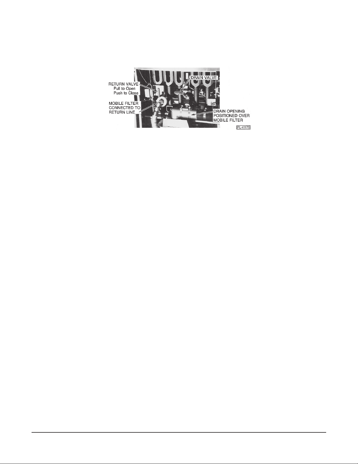
4. After oil is pumped back into individual tank:
a. Close return valve.
b. Fill tank to at least the MIN line but not past the MAX line on the back wall of the fry tank.
Fig. 4
SHORTENING LIFE
Shortening life may be extended by following these guidelines:
• Do not salt foods over the fryer.
• Use good quality shortening.
• Filter shortening daily at a minimum.
• Replace shortening if it becomes poorly flavored.
• Keep equipment and surroundings clean.
• Set thermostats correctly.
• Remove excess moisture and particles from food products before placing in fryer.
HIGH LIMIT DEVICE
If the shortening becomes overheated, a high temperature shutoff device will turn the gas valve off and
extinguish the pilot. DO NOT relight the pilot until the shortening temperature is below 300°F (149°C).
If this situation persists, contact your local Hobart authorized service office.
– 17 –
Page 18

CONTROLS — Models HGFC (Fig. 5)
START
STOP
OIL TEMP
IDLE
FRENCH FR I ES
12 3
45 6
78 9
MANUAL
START
STOP
ENTER EXIT
POWER
PL-52208
Fig. 5
DISPLAY — A twelve character display provides information during operation.
HEAT — HEAT indicator is lit when burners are on, not lit when off.
PRODUCT PADS (1-8)* — Programmable product pads select pre-programmed cooking
parameters.
MANUAL PRODUCT (9) — Manual product pad can be programmed or allows manual operation.
OIL TEMP — Press to display temperature of oil in vat.
IDLE — Toggles Idle mode on or off. Idle can be programmed to maintain
275°F or 350°F (135°C or 177°C).
▲
▲
— Green light, indicates left or right basket.
START/STOP — Starts or stops the cooking timer for a basket.
▲
▲▼, ENTER, EXIT — Moves around the menu system or edits product or system information.
▲
* Two sheets of peel-off labels with most common product names are supplied. Applicable product
names can be affixed to the appropriate Product Pad.
– 18 –
Page 19

POWER-UP
After being turned on:
1. The control executes a self-check routine (see Error Messages in this manual).
2. The control enters either Fat Melt or Heating mode.
FAT MELT
After power-up, if the oil temperature is below 135°F (52°C) and the Fat Melt mode is enabled, the fryer
enters Melt mode - MELT is displayed.
Whenever the oil temperature is below 135°F (52°C), if Fat Melt mode is enabled and the controller
is not timing a product, the fryer will be in the Melt mode. If you press Oil Temp, the oil temperature
will display.
If you will never be using solid shortening and use liquid shortening only, the controller can be
programmed so it will enter Heating mode without going into the Melt cycle. See Select Melt, Melt
Disabled in this manual.
HEATING
During Heating mode, the burners will heat to the set point of 350°F (176°C) or until a product cook
cycle is begun.
• WAIT displays and the HEAT indicator is lit.
• READY displays after reaching 335°F (168°C).
PRODUCT PADS (1-8) are used to select a product cooking cycle.
START/STOP initiates the timed cycle for either left or right basket and indicates time remaining. The
oil temperature is controlled by the programmed temperature for the selected product. After a product
cycle has begun, the product name will display with an arrow indicating left or right basket.
MANUAL PRODUCT (9) allows you to set the time and temperature for the batch.
IDLE changes to Idle mode (sets temperature back to 275°F (135°C) if programmed (see SEL
SETBACK in this manual).
OIL TEMP is pressed to display the oil temperature.
– 19 –
Page 20

TO BEGIN MELT CYCLE
1. Fill vat with shortening.
2. Press power switch ON.
DISPLAY
3. If Fat Melt is enabled and oil
temp. is below 135°F (57°C)…
MELT
4. Allow the cooking oil to heat… WAIT
5. After oil temperature reaches
335°F (168°C), a buzzer sounds…
READY
COOKING
1. Press a Product Pad [1 - 8]…
FRENCH FRIES
2. Load Basket. Press left or right
START/STOP Pad and lower XX:XX
basket. Timer counts down…*
3. When finished, buzzer sounds…* DONE
4. Press left or right START/STOP
Pad to stop buzzer.
* Display indicates left or right basket. When both baskets are in use, count down time and DONE for
the left basket are displayed on left, right basket info is displayed on right.
MANUAL COOKING OPERATION
This allows the operator to select the cooking time and temperature to cook a batch of product.
With at least one basket not in use, press the Manual pad (9).
If the previous time and temperature were OK, press START/STOP to begin cooking.
If you want to set the time and temperature, use the editor…
DISPLAY INSTRUCTION
▲▼
▲
TIME = 00:10 Use to edit the time.
▲
Press ENTER.
TEMP = XXX°F Use ; edit temperature.
▲▼
▲
▲
Press ENTER.
Press START/STOP to
begin cooking.
– 20 –
Page 21

COOKING TIME REMAINING
XX:XX YY:YY Left basket displays on left; right basket on right; time is in Minutes:Seconds. If
only one basket is cooking, the other will indicate READY or WAIT. XX:XX READY
COMPLETION
After the timer counts down to 00:00, a buzzer sounds and the display prompts DONE on the left or
right side of the display, indicating which basket is done.
Press START/STOP to remove the DONE message and stop the tone.
SUCCESSIVE PRODUCT COOKING
After selecting a product by pressing its Product Pad (1 - 8), the timer can be started by pressing the
START/STOP pad. If the START/STOP pad is pressed during a cooking cycle, the product cycle is
terminated. Fryer returns to READY.
DURING SLACK PERIODS
If the fryer is not going to be used for an extended period, oil life is enhanced by pressing Idle if Setback
is enabled. With the setback feature enabled, after 30 minutes of non-use, the fryer automatically
assumes Idle mode where it maintains 275°F (135°C) temperature. If Setback is disabled, the fryer
does not automatically go into Idle mode and will continue to maintain the last cook cycle temperature.
IDLE MODE
If setback is enabled, during idle mode, the Setback temperature of 275°F (135°C) will be maintained
until Idle is pressed.
IDLE MODE WILL SETBACK - PRESS IDLE TO RESUME
If the setback is not enabled, 350°F (177°C) is maintained during Idle mode.
IDLE MODE - PRESS IDLE TO RESUME
The purpose of the setback temperature is to extend oil life during slack periods.
OPERATOR ADVICE
OIL indicates the programmed number of hours has expired and reminds the operator that the oil
should be changed or filtered.
Reset the timer to a non-zero value to remove the message. A zero setting turns the oil timer off.
TOO HI or TOO LOW indicate invalid edit entry.
– 21 –
Page 22

USING EDITOR
Names or Messages use the 12 character alpha-display. When entering data …
▲ begins at A and increments thru the alphabet.
▼ begins with Z. Select the correct letter.
▲
moves Right one character or space.
moves Left.
▲
▲▼
▲
Use a series of to display the name or message you want.
▲
Time or Temperature …
▲▼ increment up or down (0-9). Select the correct number.
▲
moves Right one space.
moves Left.
▲
°F or °C …
▲▼ toggle between Fahrenheit and Celsius; temperature is automatically converted.
All temperatures display in the most recently edited temperature scale.
PROGRAMMING THE CONTROLLER
Enter the menu system by pressing Product Pads 2 and 3 at the same time until -FUNCTIONSis displayed. The controller must not be in a timed product cycle to enter the menu system.
▼
Step through the program using
. If you go too far, ▲will return one step.
EDIT PRODUCT RECOVERY
SEL SETBACK SELECT MELT
CALIBRATE MANUAL SETUP
BOIL OUT OIL SHUTDOWN
OIL TMR/CNTR
Description of each program element follows.
DEFINITIONS — EDIT PRODUCT
PRODUCT KEY — The Product Pad, (1 - 8).
PRODUCT NAME — Any 12 alpha characters.
COOK TIME — Minutes:Seconds of cooking duration. Controls basket lifts and buzzer.
Elastic time compensates for under- or over-temperature.
COOK TEMP — Fryer burner thermostat control.
DUTY TIME — Time between start and the duty message.
DUTY MSG — Displays after duty time lapses during cooking cycle, e.g. "shake basket".
HOLD TIME — Amount of time after the last batch is processed before product begins to
stale. Buzzer notifies when Hold Time is over.
CLR PRODUCT? — ENTER erases product from memory.
– 22 –
Page 23

OVERVIEW OF PROGRAMMING
-FUNCTIONS- EDIT PRODUCT # CHARS - TYPE UNITS - LIMITS
PRODUCT NAME 12 - ALPHA CHARACTERS [ A - Z ]
COOK TIME XX:XX - TIME MINUTES:SECONDS - [ 00:00 - 99:59 ]
COOK TEMPERATURE XXX - TEMPERATURE [ °F OR °C ] - [ 250 - 375°F ]
or [ 121 - 191°C ]
DUTY TIME XX:XX - TIME MINUTES:SECONDS - [ 00:00 - 99:59 ]
DUTY MESSAGE 12 - ALPHA CHARACTERS [ A - Z ]
HOLD TIME XX:XX - TIME MINUTES:SECONDS - [ 00:00 - 99:59 ]
SEL SETBACK ↑ ↓ - TOGGLE SETBACK - [ ON - OFF ]
ON = IDLE @ 275°F (135°C) With AUTO
OFF = IDLE @ LAST TEMP. Without AUTO
CALIBRATE XXX- TEMPERATURE °F or °C - [ XXX ± 30°F ]
or [ YYY ± 17°C ]
BOIL OUT XXX- TEMPERATURE °F or °C - [ 190 - 205°F ]
or [ 88 - 96°C ]
RECOVERY XX:XX - TIME MINUTES:SECONDS - [ 00:00 - 99:59 ]
SELECT MELT ↑ ↓ - TOGGLE MELT - [ ON - OFF ]
MANUAL SETUP ↑ ↓ - TOGGLE MANUAL - [ ON - OFF ]
OIL SHUTDOWN ↑ ↓ - TOGGLE COUNT - [ ON - OFF ]
OIL TMR/CNTR XXX - NUMERIC HOURS - [ 0 = OFF, 1 - 255 ]
– 23 –
Page 24

EDIT PRODUCT
SEL SETBACK
To Add or Change a Product Cook Cycle…
DISPLAY INSTRUCTION
READY Press 2 & 3 simultaneously.
-FUNCTIONS- Press
▼ .
EDIT PRODUCT Press ENTER.
PRODUCT KEY Press Pad Number (1-8).
PRODUCT NAME Press ENTER.
Enter the product name.
▲▼
▲
Use . When the
▲
display is OK, press EXIT.
PRODUCT NAME Press
▼ .
COOK TIME Press ENTER.
TIME = XX:XX Enter the time. Use .
▲▼
When OK, press EXIT.
COOK TIME Press
▼ .
COOK TEMP Press ENTER.
TEMP = XXX°F Enter the temperature. Use
▲▼
▲
▲
. When OK, press EXIT.
COOK TEMP Press
▼ .
DUTY TIME Press ENTER.
DT TM = XX:XX Enter duty time. Use .
▲▼
When OK, press EXIT.
ON sets the Idle temperature at 275°F (135°C); fryer
will automatically go into Idle after 30 minutes. OFF
sets the Idle temperature at 350°F (177°C) and will
not automatically enter Idle after 30 minutes. Use
▲
or ▼ to toggle SETBACK ON or SETBACK OFF.
DISPLAY INSTRUCTION
READY Press 2 & 3 simultaneously.
-FUNCTIONS- Press
EDIT PRODUCT Press
▼ .
▼ .
SEL SETBACK Press ENTER.
SETBACK OFF Press
▲ or ▼.
SETBACK ON Press EXIT.
SEL SETBACK Press EXIT.
▲
▲
-FUNCTIONS- Press EXIT.
READY
CALIBRATE
This feature allows the operator to calibrate the
temperature sensors in the fryer. Before calibrating,
temperature must be stable at 350°F (177°C).
▲
▲
DISPLAY INSTRUCTION
READY Press 2 & 3 simultaneously.
DUTY TIME Press
▼ .
DUTY MSG Press ENTER.
Enter the message. Use
▲▼
▲
▲
. When OK, press EXIT.
DUTY MSG Press
▼ .
HOLD TIME Press ENTER.
▲▼
HD TM = XX:XX Enter hold time. Use .
▲
When OK, press EXIT.
HOLD TIME Press
▼ .
CLR PRODUCT? Press EXIT.
DO NOT press ENTER unless you want to erase
the product from memory.
-FUNCTIONS- Press Exit.
READY
▲
– 24 –
-FUNCTIONS- Press
EDIT PRODUCT Press
SEL SETBACK Press
▼ .
▼ .
▼ .
CALIBRATE Press ENTER.
TEMP = 347°F Measure the vat
(175°C) temperature with a
thermometer device. Use
▲▼
▲
▲
to edit the displayed
temperature so it agrees
with the measurement.
When OK, press EXIT.
CALIBRATE Press EXIT.
-FUNCTIONS- Press EXIT.
READY
Page 25

BOIL OUT
SELECT MELT
BOIL OUT heats water in the vat for cleaning purposes
for 15 minutes. If operating at a higher altitude, the
boiling temperature may be lowered.
DISPLAY INSTRUCTION
READY Press 2 & 3 simultaneously.
-FUNCTIONS- Press
EDIT PRODUCT Press
SEL SETBACK Press
CALIBRATE Press
▼ .
▼ .
▼ .
▼ .
BOIL OUT Press ENTER.
START BOIL - To change boil temperature,
press
▼.
CH BOIL TEMP Press ENTER.
▲▼
TEMP = 195°F Alter boil temp. Use .
▲
When OK, Press EXIT.
CH BOIL TEMP Press
START BOIL
- To begin boil, press ENTER.*
▼ .
▲▼ toggles MELT DISABLE or MELT ENABLE.
ENABLE is required when using solid shortening to
automatically Melt if below 135°F (57°C).
DISPLAY INSTRUCTION
READY Press 2 & 3 simultaneously.
-FUNCTIONS- Press ▼ .
EDIT PRODUCT Press
SEL SETBACK Press
CALIBRATE Press
BOIL OUT Press
RECOVERY Press
▼ .
▼ .
▼ .
▼ .
▼ .
SELECT MELT Press ENTER.
MELT ENABLE Press
▲
MELT DISABLE When OK, press EXIT.
▲ or ▼ to toggle.
SELECT MELT Press EXIT.
-FUNCTIONS- Press EXIT.
READY
BOIL OUT
TIME = 15:00 Time Counts down or EXIT.
DRAIN VAT Suspends operation. Turn
fryer OFF.
* To return to -FUNCTIONS- press EXIT.
RECOVERY
Displays the previous recovery time, the time it takes
to recover from 275 - 325°F (135 - 163°C).
DISPLAY INSTRUCTION
READY Press 2 & 3 simultaneously.
-FUNCTIONS- Press
EDIT PRODUCT Press
SEL SETBACK Press
CALIBRATE Press
BOIL OUT Press
▼ .
▼ .
▼ .
▼ .
▼ .
RECOVERY Press ENTER.
REC TM = XX:XX Press EXIT.
-FUNCTIONS- Press EXIT.
READY
MANUAL SETUP
▲▼ toggles MANUAL ON or MANUAL OFF. ON
allows time/temp entry for the batch. OFF disables
manual operation and allows the manual pad (9) to
be reprogrammed as a regular product pad.
DISPLAY INSTRUCTION
READY Press 2 & 3 simultaneously.
-FUNCTIONS- Press
EDIT PRODUCT Press
SEL SETBACK Press
CALIBRATE Press
BOIL OUT Press
RECOVERY Press
SELECT MELT Press
▼ .
▼ .
▼ .
▼ .
▼ .
▼ .
▼ .
MANUAL SETUP Press ENTER.
MANUAL OFF Press
▼ or ▲ to toggle.
MANUAL ON When OK, press EXIT.
MANUAL SETUP Press EXIT.
-FUNCTIONS- Press EXIT.
READY
– 25 –
Page 26

OIL SHUTDOWN
OIL TMR/CNTR
The oil service has two modes:
Oil Shutdown = ON
Counter with Shutdown: The operator sets the
number of product cook cycles before oil service
action is taken by the controller. After that number
of cook cycles has elapsed, the heat will be shut
off, a SERVICE OIL message will be flashed on
the display, and the keypad will be locked out.
Turning the fryer off, then on, will clear the condition
and restore the count number set by COUNT =
XXX in the following section.
Oil Shutdown = OFF
Timer without Shutdown: The controller keeps
track of the number of hours since OIL TM = XXX
HR was set by the operator. When the time has
elapsed, a small oil indicator light will turn on.
Service of the fryer is not interrupted. The oil
indicator remains lit until a time is re-entered for
OIL TM = XXX HR in the following section. Turning
the fryer off, then on, will clear the indicator.
DISPLAY INSTRUCTION
READY Press 2 & 3 simultaneously.
-FUNCTIONS- Press ▼ .
EDIT PRODUCT Press
SEL SETBACK Press
CALIBRATE Press
BOIL OUT Press
RECOVERY Press
SELECT MELT Press
MANUAL SETUP Press
OIL SHUTDOWN Press
▼ .
▼ .
▼ .
▼ .
▼ .
▼ .
▼ .
▼ .
OIL TMR/CNTR Press ENTER.
OIL TM = XXX HR/
COUNT = XXX Use
timer
▲ or ▼
or counter. When set
to reset the
time/count is OK, press EXIT.
OIL TMR/CNTR Press EXIT.
-FUNCTIONS- Press EXIT.
READY
DISPLAY INSTRUCTION
READY Press 2 & 3 simultaneously.
-FUNCTIONS- Press
EDIT PRODUCT Press
SEL SETBACK Press
CALIBRATE Press
BOIL OUT Press
RECOVERY Press
SELECT MELT Press
MANUAL SETUP Press
▼ .
▼ .
▼ .
▼ .
▼ .
▼ .
▼ .
▼ .
OIL SHUTDOWN Press ENTER.
COUNT ON Press
▲ or ▼ to toggle.
COUNT OFF When OK, press EXIT.
OIL SHUTDOWN Press EXIT.
-FUNCTIONS- Press EXIT.
READY
If Oil Shutdown is OFF:
The controller will alert the operator when the oil
needs to be changed. OIL TM = XXX sets the
number of hours before the alert will be given.
If Oil Shutdown is ON:
The controller will shut off the heat, lock out the
keypad, and signal to service the oil. The fryer
must be turned off to clear this condition. COUNT
= XXX sets the number of cook cycles before
shutoff. Turning the fryer off, then on, automatically
restores COUNT = XXX to the number originally
set by the operator.
– 26 –
Page 27

ERROR MESSAGES
TEMP TOO HI indicates that the fryer has operated at a higher than normal temperature and has shut
down and become inoperable.
CALL SERVICE indicates that the fryer has a problem that demands the attention of a Hobart
authorized servicer. The fryer will shut down and become inoperable.
Arrows flashing indicates RAM failure. If any failures are present, the fryer remains in back-up mode.
CLEANING
WARNING: UNPLUG FRYER BEFORE CLEANING.
Daily
1. Clean all exterior surfaces of your fryer at least once daily.
2. Use a damp cloth with warm water and a mild soap or detergent.
3. Rinse thoroughly, then polish with a soft dry cloth.
4. Keep the fryer exterior clean and free of accumulated grease to prevent stubborn stains from
forming. If regular cleaning is neglected, grease will be burned on and discolorations may form.
• Remove discolorations by washing with any detergent or soap and water.
• Use a self-soaping scouring pad for particularly stubborn discolorations.
• Always rub with the GRAIN in a horizontal direction.
5. Minimize fingerprints by applying a cleaner that will leave a thin, oily or waxy film.
• Fingerprints are sometimes a problem on highly polished surfaces of stainless steel.
6. DO NOT use a scouring pad or harsh cleaners on the computer keypad, especially the display area.
Weekly or as Required
1. Once the shortening has been drained, flush out scraps and sediment with a small amount of warm
shortening.
2. Allow the tank to drain thoroughly.
3. Close the drain valve and fill the tank with a non-corrosive, grease-dissolving commercial cleaner.
Follow the manufacturer's instructions.
4. Set the thermostat at a temperature recommended by the manufacturer of the commercial cleaner
and boil the solution for 15 to 20 minutes.
• If cleaner is a water based chemical, temperature may be 190 - 212°F (80 - 100°C). Set the
temperature as low as possible.
5. Monitor boiling to prevent overflow.
6. Drain the cleaning solution from the tank.
7. Close the drain valve and refill the tank with water.
8. Add 1 cup (227 mL) of vinegar to neutralize alkaline left by the cleaner.
9. Bring the solution to a boil and allow it to stand for a few minutes.
– 27 –
Page 28

10. Drain the tank.
11. Rinse tank thoroughly with clear, hot water. All traces of cleaner must be removed.
12. Dry the tank thoroughly.
13. Close the drain valve.
14. Add shortening to at least the MIN line but not past the MAX line.
The fryer is now ready for use.
MAINTENANCE
WARNING: HOT OIL AND PARTS CAN CAUSE BURNS. USE CARE WHEN OPERATING, CLEANING
AND SERVICING THE FRYER.
WARNING: SPILLING HOT FRYING COMPOUND CAN CAUSE SEVERE BURNS. DO NOT MOVE
FRYER WITHOUT DRAINING ALL FRYING COMPOUND FROM THE TANK.
WARNING: DISCONNECT ELECTRICAL POWER SUPPLY BEFORE SERVICING THE FRYER.
LUBRICATION
Motors used on basket lifts are permanently lubricated.
VENT
Annually, when fryer is cool, check the flue and clear any obstructions.
SERVICE
Contact your local Hobart Service office.
FORM 34086 Rev. A (Oct. 2000) PRINTED IN U.S.A.
– 28 –
 Loading...