

Page 1
s
OM-257 074C
2014−02
Pro Series
Auto-Darkening Welding Helmet
www.HobartWelders.com
Page 2

TABLE OF CONTENTS
SECTION 1 − WELDING HELMET SAFETY PRECAUTIONS − READ BEFORE USING 1.....
1-1. Symbol Usage 1.............................................................
1-2. Arc Welding Hazards 1.......................................................
1-3. Proposition 65 Warnings 3....................................................
1-4. Lens Shade Selection Table 3.................................................
1-5. Principal Safety Standards 3..................................................
SECTION 2 − SPECIFICATIONS 4.....................................................
SECTION 3 − OPERATING INSTRUCTIONS 5..........................................
3-1. Helmet Controls 5...........................................................
3-2. Reset Button And Low Battery Indicator 5.......................................
3-3. Lens Delay Control 6.........................................................
3-4. Variable Shade Control (No. 8 − 13) 6...........................................
3-5. Sensitivity/Grind Mode Control 7...............................................
SECTION 4 − ADJUSTING HEADGEAR 8..............................................
SECTION 5 − REPLACING THE LENS COVERS 9......................................
5-1. Replacing Outside Lens Cover 9...............................................
5-2. Replacing Inside Lens Cover 10................................................
SECTION 6 − REPLACING THE BATTERY 11..........................................
SECTION 7 − INSTALLING OPTIONAL MAGNIFYING LENS 12..........................
SECTION 8 − MAINTENANCE 12.....................................................
SECTION 9 − TROUBLESHOOTING 13................................................
SECTION 10 − PARTS LIST 14.......................................................
SECTION 11 − LIMITED WARRANTY 15...............................................
Page 3
SECTION 1 − WELDING HELMET SAFETY PRECAUTIONS −
READ BEFORE USING
helmet 2013-09
Protect yourself and others from injury — read, follow, and save these important safety
precautions and operating instructions.
1-1. Symbol Usage
DANGER! − Indicates a hazardous
situation which, if not avoided, will
result in death or serious injury. The
possible hazards are shown in the
adjoining symbols or explained in
the text.
Indicates a hazardous situation
which, if not avoided, could result in
death o r serious injury. The possible
hazards are shown in the adjoining
symbols or explained in the text.
NOTICE − Indicates statements not related to
personal injury.
Indicates special instructions.
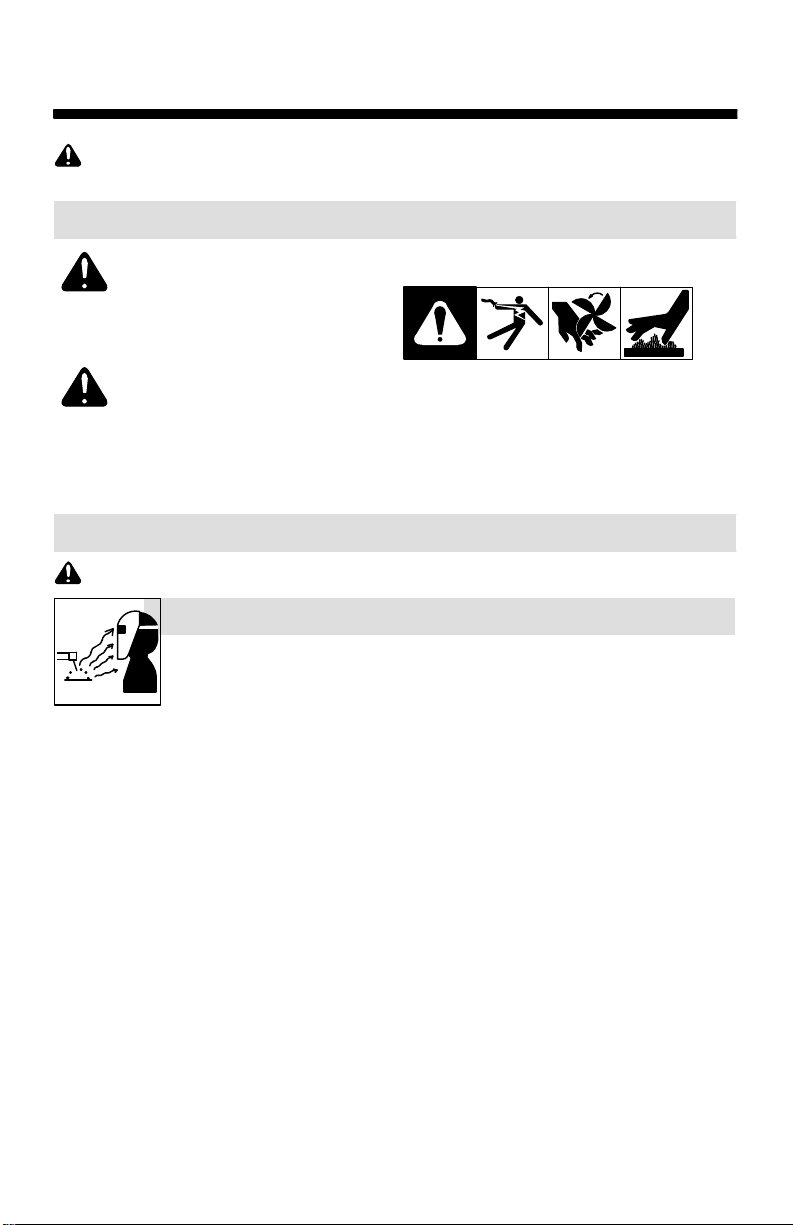
This group of symbols means Warning! W atch
Out! ELECTRIC SHOCK, MOVING PARTS,
and HOT PARTS hazards. Consult symbols
and related instructions below for necessary
actions to avoid the hazards.
1-2. Arc Welding Hazards
Only qualified persons should install, operate, maintain, and repair this unit.
ARC RAYS can burn eyes and skin.
Arc rays from the welding process produce intense visible and invisible (ultraviolet and infrared) rays that can burn eyes and skin. Sparks fly off from the weld.
Wear a welding helmet fitted with a proper shade of filter to protect your face and eyes when
welding or watching (see ANSI Z49.1 and Z87.1 listed in Safety Standards). Refer to Lens
Shade Selection table in Section 1-4.
Wear approved safety glasses with side shields under your helmet.
Use protective screens or barriers to protect others from flash, glare, and sparks; warn
others not to watch the arc.
Wear body protection made from durable, flame−resistant material (leather, heavy cotton,
wool). Body protection includes oil-free clothing such as leather gloves, heavy shirt, cuffless
trousers, high shoes, and a cap.
• Before welding, adjust the auto-darkening lens sensitivity setting to meet the application.
• Stop welding immediately if the auto-darkening lens does not darken when the arc is struck.
See the Owner’s Manual for more information.
OM-257 074 Page 1
Page 4
WELDING HELMETS do not provide unlimited eye, ear, an
d
t
face protection.
Arc rays from the welding process produce intense visible and invisible (ultraviole
and infrared) rays that can burn eyes and skin. Sparks fly off from the weld.
Use impact resistant safety spectacles or goggles and ear protection at all times when using
this welding helmet.
Do not use this helmet while working with or around explosives or corrosive liquids.
Do not weld in the overhead position while using this helmet.
Inspect the auto-lens frequently. Immediately replace any scratched, cracked, or pitted cover
lenses or auto-lenses.
NOISE can damage hearing.
Noise from some processes or equipment can damage hearing.
W ear approved ear protection if noise level is high.
READ INSTRUCTIONS.
Read and follow all labels and the Owner’s Manual carefully before in-
stalling, operating, or servicing unit. Read the safety information at the beginning of the manual and in each section.
Use only genuine replacement parts from the manufacturer.
Perform maintenance and service according to the Owner’s Manuals, industry standards,
and national, state, and local codes.
FUMES AND GASES can be hazardous.
Welding produces fumes and gases. Breathing these fumes and gases can be
hazardous t o your health.
Keep your head out of the fumes. Do not breathe the fumes.
If inside, ventilate the area and/or use local forced ventilation at the arc to remove welding
fumes and gases. The recommended way to determine adequate ventilation is to sample f or
the composition and quantity of fumes and gases to which personnel are exposed.
If ventilation is poor, wear an approved air-supplied respirator.
Read and understand the Safety Data Sheets (SDSs) and the manufacturer’s instructions for
adhesives, coatings, cleaners, consumables, coolants, degreasers, fluxes, and metals.
Work in a confined space only if it is well ventilated, or while wearing an air-supplied respirator.
Always have a trained watchperson nearby. Welding fumes and gases can displace air and
lower the oxygen level causing injury or death. Be sure the breathing air is safe.
Do not weld in locations near degreasing, cleaning, or spraying operations. The heat and rays
of the arc can react with vapors to form highly toxic and irritating gases.
Do not weld on coated metals, such as galvanized, lead, or cadmium plated steel, unless the
coating i s removed from the weld area, the area is well ventilated, and while wearing an airsupplied respirator. The coatings and any metals containing these elements can give off toxic
fumes if welded.
OM-257 074 Page 2
Page 5

1-3. Proposition 65 Warnings
Welding or cutting equipment produces fumes or gases which contain chemicals known
to the State of California to cause birth defects and, in some cases, cancer. (California
Health & Safety Code Section 25249.5 et seq.)
This product contains chemicals, including lead, known to the state of California to cause
cancer, birth defects, or other reproductive harm. Wash hands after use.
1-4. Lens Shade Selection Table
Process
Shielded Metal Arc
Welding (SMAW)
Gas Metal
Arc Welding
(GMAW)
Flux Cored
Arc Welding
(FCAW)
Gas Tungsten Arc
Welding (TIG)
Air Carbon
Arc Cutting (CAC-A)
Plasma Arc
Cutting (PAC)
Plasma Arc Welding
(PAW)
Electrode Size
in. (mm)
Less than 3/32 (2.4)
3/32−5/32 (2.4−4.0)
5/32−1/4 (4.0−6.4)
More than 1/4 (6.4)
Light
Heavy
Arc Current
in
Amperes
Less than 60
60−160
160−250
250−550
Less than 60
60−160
160−250
250−500
Less than 50
50−150
150−500
Less than 500
500−1000
Less than 20
20−40
40−60
60−80
80−300
300−400
400−800
Less than 20
20−100
100−400
400−800
Minimum
Protective
Shade No.
7
8
10
11
7
10
10
10
8
8
10
10
11
4
5
6
8
8
9
10
6
8
10
11
Suggested
Shade No.
(Comfort)*
−−
10
12
14
−−
11
12
14
10
12
14
12
14
4
5
6
8
9
12
14
6−8
10
12
14
Reference: ANSI Z49.1:2005
* Start with a shade that is too dark to see the weld zone. Then, go to a lighter shade which gives a
sufficient view of the weld zone without going below the minimum.
1-5. Principal Safety Standards
Safety in Welding, Cutting, and Allied Processes, ANSI Standard Z49.1, is available as a free download f r o m the American W elding Society at http://www.aws.org or purchased from Global Engineering
Documents (phone: 1-877-413-5184, website: www.global.ihs.com).
Safe Practice For Occupational And Educational Eye And Face Protection, ANSI Standard Z87.1,
from American National Standards Institute, 25 West 43rd Street, New York, NY 10036 (phone:
212-642-4900, website: www.ansi.org).
OM-257 074 Page 3
Page 6

SECTION 2 − SPECIFICATIONS
Viewing Field 3.82 x 2.36 in. (97 x 60mm)
Reaction Time 0.0000333sec (1/30,000)
Available Shades Darkened State: No. 8 − No. 13 / Light State: No. 3
Sensitivity/Grind Mode Control Adjusts for varying ambient light and welding arc
Delay Control Slows lens dark-to-light state between 0.1 and
Automatic Power Off Shuts lens Off 15−20 minutes after last arc is struck
Low Battery Indicator Red LED light illuminates to indicate 2−3 days
Power Supply CR2450 Lithium Batteries (Two Required)
Sensors Independent/Redundant (Four)
Operating Temperature 23F to 131F / −5C to +55C
provides continuous UV and IR protection
1.0 seconds
remaining battery life
When stored in extremely cold temperatures, warm
helmet t o ambient temperature before welding.
Storage Temperature −14F to 158F / −10C to +70C
When stored in extremely cold temperatures, warm
helmet t o ambient temperature before welding.
Total Weight 19.9 oz. (565 g)
Standards ANSI Z87.1-2010 and DIN/CSA/TUV
Warranty Two years from date of purchase (see Section 11)
OM-257 074 Page 4
Page 7
SECTION 3 − OPERATING INSTRUCTIONS
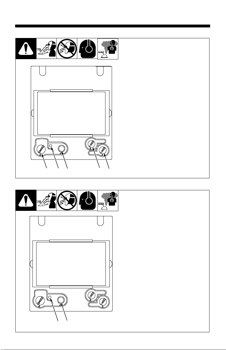
3-1. Helmet Controls
21 53
4
3-2. Reset Button And Low Battery Indicator
1 Reset Button (See Section 3-2)
2 Low Battery Indicator
(See Section 3-2)
3 Variable Shade Control (See
Section 3-4)
4 Sensitivity/Grind Mode Control
(See Section 3-5)
5 Lens Delay Control
(See Section 3-3)
21
The auto-darkening lens
turns on (darkens) automatically when welding begins
and turns off 15 − 20 minutes
after welding stops.
1 Reset Button
Press Reset button to check if
the lens is working properly.
When the Reset button is
pressed, the lens should darken
twice and return to the clear
state. Do not use the helmet if the
lens does not function as described. (See Section 9, T roubleshooting.)
2 Low Battery Indicator
The low battery indicator lights
when 2−3 days of battery life remain.
If battery power is low , install new
CR2450 lithium batteries (see
Section 6).
OM-257 074 Page 5
Page 8

3-3. Lens Delay Control
1
3-4. Variable Shade Control (No. 8 − 13)
1 Lens Delay Control
The lens delay control is used to ad-
just the time for the lens to switch to
the clear state after welding.
The delay is particularly useful in
eliminating bright after-rays present
in higher amperage applications
where the molten puddle remains
bright momentarily after welding.
Lens delay adjusts from min (0.10
second) to max (1.0 second).
OM-257 074 Page 6
1 Variable Shade Control
(No. 8 − 13)
Use the control to adjust the lens
shade in the darkened state. Use
the table in Section 1-4 to select
proper shade control setting
based on your welding process.
Start at shade 12 and adjust lighter
to suit the welding application and
your personal preference.
1
Page 9

3-5. Sensitivity/Grind Mode Control
1
1 Sensitivity/Grind Mode Control
Weld Mode
Use control to make the lens more responsive to d i fferent light levels in various welding processes. Use a Mid-Range or
30−50% sensitivity setting for most ap-
plications.
It may be necessary to adjust helmet sensitivity to accommodate different lighting conditions or i f lens is flashing On and Off. Adjust helmet sensitivity as follows:
Adjust helmet sensitivity in lighting con-
ditions helmet will be used in.
Turn sensitivity control to lowest
setting.
Press Reset button to turn helmet On.
Helmet lens will darken twice and then
clear.
Face the helmet in the direction of use,
exposing i t t o the surrounding light conditions.
Gradually turn sensitivity setting clock-
wise until the lens darkens, then turn
sensitivity control counterclockwise
until slightly past setting where lens
clears. Helmet is ready for use. Slight
readjustment may be necessary for
certain applications or if lens is flashing
on and off.
Grind Mode
Do not weld in the Grind mode; the lens
will not darken.
To use the Grind mode, turn the Sensitivity
control clockwise to the far right position
(Grind). To resume welding, return the control to the desired sensitivity setting.
Recommended Sensitivity Settings
Stick Electrode Mid-Range
Short Circuiting (MIG) Low/Mid-Range
Pulsed & Spray (MIG) Mid-Range
Gas Tungsten Arc (TIG) Mid/High-Range
Plasma Arc Cutting/Welding Low/Mid-Range
Grind Mode Grind Position − Far Right (Clockwise)
OM-257 074 Page 7
Page 10

SECTION 4 − ADJUSTING HEADGEAR
There are four headgear
1 Headgear Top
1
2
4
Adjusts headgear for proper
depth on the head to ensure
correct balance and stability.
2 Headgear Tightness
To adjust, turn the adjusting
knob located on the back of
the headgear left or right to
desired tightness.
3 Angle Adjustment (Not
Seven slots on the right side
of the headband provide adjustment for the forward tilt of
the helmet. To adjust, lift and
reposition the control arm to
the desired position.
4 Distance Adjustment
Adjusts the distance be-
tween the face and the lens.
To adjust, press black tabs
on the top and bottom of the
pivot point and use other
hand to slide headgear forward or backward. Release
tabs. (Both sides must be
equally positioned for proper
vision.)
Numbers on the adjust-
adjustments: headgear
top, tightness, angle adjustment, and distance
adjustment.
Shown)
ment slides indicate set
position so both sides
can be adjusted equally.
OM-257 074 Page 8
Page 11
SECTION 5 − REPLACING THE LENS COVERS
l
-
.
t
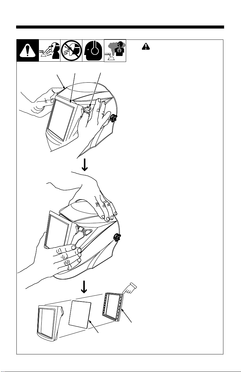
5-1. Replacing Outside Lens Cover
2
1
2
! Never use the auto-darkening
lens without the inside and
outside lens covers properly
installed. Welding spatter wil
damage the auto-darkening
lens and void the warranty.
1 Front Lens Holder
2 Release Points
3 Lens Cover
4 Gasket
Remove fr o n t l e n s h o l d e r b y p r e s s
ing release points and pulling the
holder away from the helmet.
Remove lens cover and gasket from
the holder. Replace lens cover and
reinstall gasket and lens in holder
Reinstall holder in helmet.
Be sure the holed side of gaske
faces the lens cover.
Be sure the holed side of gasket
faces the lens cover.
4
3
OM-257 074 Page 9
Page 12

5-2. Replacing Inside Lens Cover
! Never use the auto-darkening
lens without the inside and outside lens covers properly
installed. Welding spatter will
damage the auto-darkening
lens and void the warranty.
1 Lens Assembly
2 inside Lens Cover
Remove the lens cover holder (see
Section 5-1). Remove lens assembly.
Remove the inside lens cover by pry-
ing the cover up at either thumbnail
opening at each side of the cover.
Slide cover it out of either side of
frame. Replace lens cover and reinstall the assembly in the helmet by r e versing the above procedure.
Be sure the cover lens is seated
properly (flat) to prevent fogging.
2
1
1
804 817 / 804 818
OM-257 074 Page 10
Page 13

SECTION 6 − REPLACING THE BATTERY
To replace the batteries, remove
the auto-darkening lens
assembly (see Section 5).
1 Battery Tray
1
++
After removing the lens assembly,
slide the battery holding trays out
and remove the old batteries.
Replace with CR2450 lithium batteries (two required).
Be sure Positive (+) side of the
battery faces up (toward inside
Be sure Positive (+)
side of battery faces up.
of helmet).
Reinstall the battery trays. To test,
press the Reset button. The lens
should flash dark twice. Reinstall
the lens assembly.
Left and right battery trays are
not interchangeable. The
auto−darkening helmet will not
work if battery trays are
installed on the wrong sides.
OM-257 074 Page 11
Page 14

SECTION 7 − INSTALLING OPTIONAL MAGNIFYING LENS
1 Optional Magnifying Lens
Starting a t the bottom, slide magni-
fying lens into the helmet retaining
brackets. Align the magnifying lens
with the auto-darkening lens assembly.
Remove lens holding frame
(with auto-darkening lens)
from helmet shell.
Remove auto-darkening
lens from lens holder.
Position lens holder with
magnifying lens holding
tabs facing toward you.
From the bottom up, slide
magnifying lens into position. (Slide magnifying lens
up or down slightly as desired.)
Reinstall the auto-darkening
1
lens in the lens holder.
Reverse procedure to re-
move magnifying lens.
T o prevent lens fogging, install
flat side of magnifying lens toward auto-darkening lens.
804 818
SECTION 8 − MAINTENANCE
NOTICE − Never use solvents or abrasive cleaning detergents.
NOTICE − Do not immerse the lens assembly in water.
The helmet requires little maintenance. However, for best performance clean
after each use. Using a soft cloth dampened with a mild soap and water solution,
wipe the cover lenses clean. Allow to air dry. Occasionally, the filter lens and
sensors should be cleaned by gently wiping with a soft, dry cloth.
OM-257 074 Page 12
Page 15
SECTION 9 − TROUBLESHOOTING
Trouble Remedy
Auto lens not ON – autolens will not darken momentarily when the Reset
button is pressed.
Not switching – auto-lens
stays light and will not
darken when welding.
Not Switching – auto-lens
stays dark after the weld
arc is extinguished, or the
auto-lens stays dark when
no arc is present.
Sections of the auto-lens
are not going dark, distinct
lines separate the light and
dark areas.
Switching or Flickering –
the auto-lens darkens then
lightens while the welding
arc is present.
Inconsistent or lighter
auto-lens shading in the
dark-state, noticeable on
the outside edges and corners.
Check batteries and verify they are in good condition and installed
properly. Also, check battery surfaces and contacts and clean if
necessary. Check battery for proper contact and gently adjust
contact points if necessary. This is particularly important if the
helmet has been dropped. Verify left and right battery trays are
installed on the correct sides.
Stop welding immediately: Press the Reset button if lens is AutoOn type. If lens if Manual-On type, make sure the lens is turned
On. If power is on, review the sensitivity recommendations and
adjust sensitivity. Clean lens cover and sensors of any obstructions. Make sure the sensors are facing the arc; angles of 45 or
more may not allow the arc light to reach the sensors.
Fine-tune the sensitivity setting by making small adjustments to
the control by turning it toward the “min” setting. In extreme light
conditions, it may be necessary to reduce the surrounding light
levels.
Stop welding immediately: The auto-lens may be cracked which
can be caused by the impact of dropping the helmet. Weld spatter
on the auto lens may also cause cracking. (The lens may need to
be replaced; most cracked lenses are not covered by warranty).
Review the sensitivity setting recommendations and increase the
sensitivity if possible. Be sure the arc sensors are not being
blocked from direct access to the arc light. Check the lens cover
for dirt and spatter that may be blocking the arc sensors. Increasing Lens Delay 0.1 − 0.3 second may also reduce switching.
Referred to as an angle of view effect, auto-darkening lenses
have an optimum viewing angle. The optimum viewing angle is
perpendicular or 90 to the surface of the auto-lens. When that
angle of view varies in the dark-state, welders may notice slightly
lighter areas at the outside edges and the corners of the lens. This
is normal and does not represent any health or safety hazard.
This effect may also be more noticeable in applications where
magnifying lenses are used.
OM-257 074 Page 13
Page 16
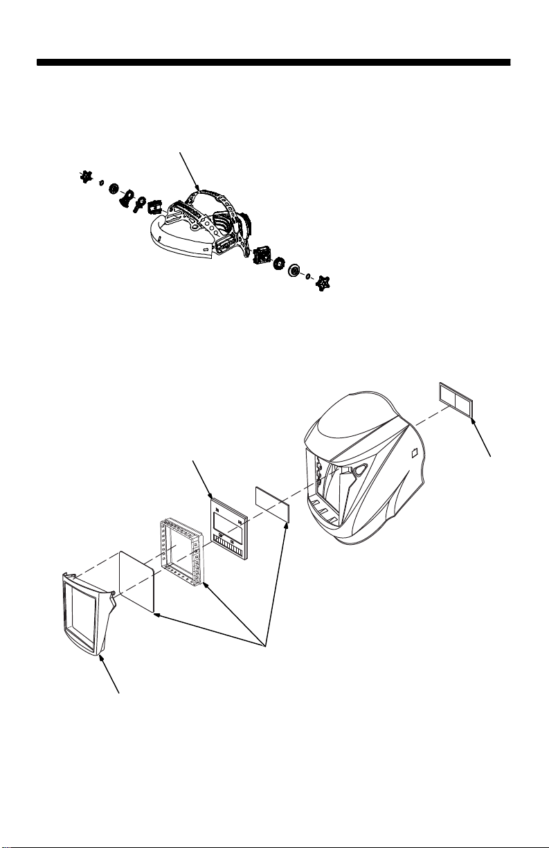
SECTION 10 − PARTS LIST
1
5
Figure 10-1. Pro Series Auto-Darkening Welding Helmet
OM-257 074 Page 14
4
3
2
Page 17

Item
No. Quantity
Part
No.
Description
Figure 10-1. Pro Series Auto-Darkening Welding Helmet
1 770759 Headgear, Gray 1........ .... .........................................
2
♦770274 Diopter Lens 150X 1........ ... ......................................
♦770275 Diopter Lens 175X 1.......... ... ......................................
♦770276 Diopter Lens 200X 1.......... ... ......................................
♦770277 Diopter Lens 250X 1.......... ... ......................................
3 770612 Cover Lens (Includes Front Lens Cover Gasket, 1........ .... .............
4 770764 Auto-Darkening Lens 1........ .... ....................................
5 770615 Front Lens Holder 1........ .... .......................................
Front Lens Covers, 2 Inside Lens Covers)
Battery, Lithium CR2450 (Not Shown) 2...................... ......................
♦ Optional
SECTION 11 − LIMITED WARRANTY
LIMITED WARRANTY – Subject to the terms and conditions below. Hobart Brothers
Co., Troy, Ohio, warrants to its original retail purchaser that the new Hobart equipment sold after the effective date of this limited warranty is free of defects in material
and workmanship at the time it is purchased at the retailer. THIS WARRANTY IS EXPRESSL Y IN LIEU OF ALL OTHER WARRANTIES, EXPRESS OR IMPLIED, INCLUDING THE WARRANTIES OR MERCHANTABILITY AND FITNESS.
Hobart auto-darkening lens helmets are warranted for two (2) years from the date
of purchase. Proof of purchase is required for warranty transactions so it is
imperative that a copy of the original invoice or sales receipt be retained.
For warranty transactions, contact your original Hobart retailer or call
1−800−332−3281
Hob Helm 2014-01
Effective January 1, 2014
OM-257 074 Page 15
Page 18

Notes
Work like a Pro!
Pros weld and cut
safely. Read the
safety rules at
the beginning
of this manual.
Page 19

Notes
Work like a Pro!
Pros weld and cut
safely. Read the
safety rules at
the beginning
of this manual.
Page 20

Hobart Brothers Co.
2200 Corporate Drive
Troy, OH 45373 USA
Phone: 800-332-3281
Visit our website at
www.HobartWelders.com
ORIGINAL INSTRUCTIONS − PRINTED IN USA © 2014 Hobart Welders 2014-01
 Loading...