

Page 1

INSTRUCTION MANUAL
.
.
.
with Replacement Parts
DISHWASHER
(INCLUDES MOTOR PARTS)
THlS MANUAL REPLACES AND SHOULD BE USED
INSTEAD OF FORM
PRIOR ML'S COVERED
12364C
IN
(9-80)
THlS MANUAL:
A
product
FORM
13830 15-81
of
HOBART CORPORATION
TROY,
OHIO
45374
Page 2

pue
slapow ayl
zt-~\d
~zL-I/u\~
.sAayseMys!p asu !A Aa$eM ysaA4 '3!$ecuolne
-!was aAe
1
aY1
y$!~
pue
'01)
z
1-fly
OM$
AO$OU
'a~n~e~ad
e
e
a$e~od~o3u! hay
$UOAJ
pa3ueleq~a$uno3-uou
.s~aua$se4 ou sa~!nb
3!~01$3a13 apls p!los
-II!~ paw!$ pue uo!~a$o~d
'5)
s~oop ap!s pa3ueleq~a$uno3
10~~~103
-wa$ Aa$eM 'apA3 paw!$ ayl sa$elnEia~ y3!y~ cua$sAs
AayseMys!p n~y~$y6!e~$s e s! lapow
(1
'6!j
~oop uo!$3adsu!
-aA jaued ~uoi4 pJE?pue$s ayl'(l '6!j
Page 3

INSTRUCTIONS
AM-12
HEATER PROTECTION
A float
turn off the heat supply if the water level
low. Once the water level returns to
the heating circuit
is
located in the wash tank to automatically
a
safe level,
is
operational if heat
is
is
too
de-
manded.
is
Tank water
heated by steam, gas, or electricity.
REDUCED VOLTAGE CONTROL (STANDARD)
is
A control transformer
used to provide low
voltage for the solid state control circuits. This
control transformer also supplies 1 15 V.A.C. to the
control components.
INSTALLATION
LOCATION
Adequate space must be available to open and
(6,
Fig. 1
).
service the control box
is
mounted 4-518" below the dish table height
when shipped from the factory. It can be changed
12-518" below the dish table by removing two
to
bolts and reinstalling in the two lower holes
provided.
Set the dishwasher in
its
desired location. Adjust
the height and level by turning the threaded feet
(7, Fig. 1). Make sure the dishwasher
making plumbing connections.
The control box
is
level before
Drain
Connect the drain to the sewer using
Left-hand drain
is
standard. Interchange plug
for a right-hand drain. If a grease trap
by code,
of 42 gallons per minute.
it
should have a minimum flow capacity
.
2" pipe.
is
required
Water Supply
The supply water should have a temperature of
180"-195" F. minimum and have a flow pressure
of 15 to 25
P.S-I. at the pressure gauge tee beside
the fill (solenoid) valve.
Use
314" pipe for connecting the water supply line
to line strainer which
is
assembled directly ahead
of the fill (solenoid) valve. The line strainer pre-
vents foreign matter from reaching the solenoid
25
valve. If flow pressure exceeds
P.S.I., a pressure
reducing valve (not furnished) must be installed in
the water supply line.
Gas Heat
Check gas data plate (9, Fig.
1) attached to dish-
washer or tag attached to gas burner tubing for
type of
Connect gas burner to
gas
to be used.
gas
supply. Check gas burner
compression fittings to assure they have not
loosened during shipment.
Dish tables (1, Fig. 2) should be turned down and
fit into the dishwasher. Use a sealer between table
and tank lip to prevent leakage. Fasten the dish
tables to the tank lip with truss head screws.
Plumbing connections must comply with applicable sanitary, safety and plumbing codes.
U
Fig.
2
is
A capped "tee" (not supplied)
recommended to
catch loose particles in front of the valve.
The burner
not adjustable. If line pressure
is
is
above 7" W.C. (natural gas) or 1 1 " W.C. (L.P. gas),
an additional regulator valve (not supplied) must
be installed.
The burner
circuitry. There
is
ignited automatically by solid state
is
no pilot light. Gas flow
is
regu-
lated by the temperature control circuit through a
solenoid valve.
If a failure occurs in the gas heat control board or
gas pressure, the reset button, located on the side
of the gas burner control box, will pop out. This
completely shuts off the gas heat system. To reset,
push the button in. If system does not reset,
contact an authorized Hobart service office.
Steam Heat
The steam supply must be between 15 and 50 P.S.
flowing pressure. Steam flow
solenoid valve
as
well
as
a
is
controlled by
mechanical globe valve.
I.
a
Page 4
AM-1 2 INSTRUCTIONS
A
314"
union connection, for steam supply line,
is located behind the control box.
A solid state circuit board controls the steam valve
is
to provide shut-off. When the dishwasher
not in
use, close the globe valve in the line ahead of the
solenoid valve.
ELECTRICAL COhINECTIONS
Before making electrical connections, check the
(4,
Fig.
1)
specifications on machine data plate
to
assure they agree with those of your electrical
service.
Electrical and grounding connections must comply
with the
trical
a~~licable ~ortions of the National Elec-
cod;' and/or 'other local electrical codes.
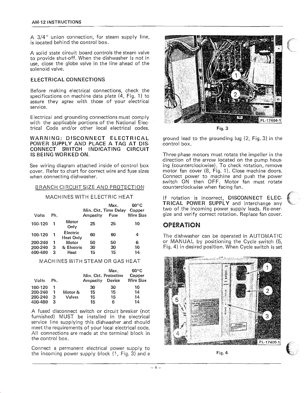
Fig.
3
WARNIIVG: DISCONNECT ELECTRICAL
POWER SUPPLY AND PLACE A TAG AT DISCONNECT SWITCH
.INDICATING CIRCUIT
IS BEING WORKED ON.
See wiring diagram attached inside of control box
cover. Refer to chart for correct wire and fuse sizes
when connecting dishwasher.
CI
BRANCH
MACHINES
Volts Ph.
100-120
100-120
200-240
200-240
400480
RCUlT SIZE AND PROTECTION
WITH ELECTRIC HEAT
Max.
25
60 4
1
1
3
3
Motor
Only
Electric
Heat Only
Motor
&
Electric
Heat
Min. Ckt. Time Delay Copper
Ampacity Fuse Wire Size
25
50 50
30 30 10
15 15 14
60°C
6
MACHIkIES WITH STEAM OR GAS HEAT
Volts Ph.
100-120
200-240
2013-240
4.00-480 3 15
I
1
3
Motor
Valves
Min. Ckt. Protective Copper
Ampacity Device Wire Size
30
15
&
15 15 14
Max.
30
15
6
6G°C
a
o
14
14
ground lead to the grounding lug
(2,
Fig.
3)
in the
control box.
Three-phase motors must rotate the impeller in the
direction of the arrow located on the pump hous-
ing (counterclockwise). To
(5,
motor fan cover
Fig.
check rotation, remove
1
).
Close machine doors.
Connect power to machine and push the power
switch ON then OFF. Motor fan must rotate
counterclockwise when facing fan.
If rotation is incorrect,
TRlCAh POWER SUPPLY
DISCONNECT ELEC-
and interchange any
two of the incoming power supply leads. Re-energize and verify correct rotation. Replace fan cover.
OPERATION
The dishwasher can be operated in AU-TORIIATIC
or MANUAL by positioning the Cycle switch
Fig.
4)
in desired position. When Cycle switch
is
(5,
set
$-
k-
A fused disconnect switch or circuit breaker (not
furnished) MUST be instailed in the electrical
service
l'ine supplying this dishwasher and should
meet the requirements of your local electrical c~de.
,411
connections are made
at
the terminal blocl< in
the control box.
Connect
the incoming power
a
permanent electrical power supply to
sr-lpply b!ock
(1,
Fig.
3)
and
a
Fig.
4
Page 5

for AUTOMATIC, the WASHIRINSE switch (4,
Fig. 4) must be in the OFF position. When Cycle
switch
accomplished when WASHIR INSE switch
is
set
for MANUAL, wash operation
is
is
in
WASH position. To rinse in MANUAL operation,
WASH/R\NSE switch in RINSE position for
hold
desired rinse time.
When operating the dishwasher in AUTOMATIC
1)
setting, close door (5, Fig.
(3,
Fig.
4)
pilot light
If cycle
is
interrupted, such as opening and closing
the door to add
goes off, cycle
a
dish, the timer resets and starts
new cycle. This feature provides
to start cycle. When
is
comp!eted.
a
complete
cycle to insure proper cleaning ~f an added article.
6efore opening the door during a cycle, first turn
off POWER switch;
then wait
10
seconds to avoid
water splashing from the wash arms.
a
INSTRUCTIONS
Fig.
6
AM-12
model, the front inspection door (10, Fig.
I)
must
be closed before counterbalanced doors can be
lowered.
Push POWER switch
release timed
Fl LL switch
(1, Fig.
automatic fill operation. Wait a full 2 minutes
4)
to ON. Push and
(2,
Fig. 4) to start
18
seconds for the timed fill cycle to complete and
shut off.
The wash thermometer
(1, Fig. 1) should register
150"-168" F. during wash cycle. The rinse ther-
mometer
(1 1, Fig.
I),
during rinsing operation,
should register 180"-195" F. minimum. These tem-
pera-tures are necessary for dishwashing and sanitization.
Fig.
5
PREPARATION
Place overflow tube
(2,
Fig.
5),
overflow cover (1,
Scrape the dishes to remove large partic!es of food
and debris. Water-scrape the dishes by means of
spray of water from the water system or by
Fig. 5), end cover (1, Fig. 6), slanted strainer (2, stream of recirculating water before or after
Fig. 6) and strainer bucket
(3,
Fig. 6) in position.
Scatter the initial charge of detergent on the When racking dishes DO
slanted strainer. Replenish as needed unless
auto-
matic detergent dispenser has been added by others.
racking the dishes.
NOT stack one on top of
another. Water must have free access to both sides
of every dish.
a
a
Close the counterbalanced doors (5, Fig. 1) which
automatically closes the drain. On straight-thru
Stand plates and flat dishes up edgewise in mixed
dish rack (Fig.
7).
Page 6
AM-12
INSTRUCTIONS
Cups, glasses, and bowls should be placed open-side
down (bottoms up) in cup, glass, and silver rack
7).
(Fig.
Knives, forks, spoons and small pieces should be
scattered loosely over screen bottom of cup, glass,
and silver rack.
After filling rack, raise the doors (5, Fig. 1) and
slide rack into dishwasher. Close the doors. Wash
and rinse cycle starts automatically and stops after
completion.
CLEANING
Push POWER switch (1, Fig.
4)
to OFF.
Open doors. Clean off "soiled" and "clean" dish
tables into dishwasher. Drain machine by pulling
drain lever (3, Fig. 5).
Remove and empty slanted strainer (2, Fig. 6) and
strainer basket (3, Fig. 6). Wash and rinse thoroughly.
Raise overflow cover (1, Fig. 5) and remove over-
(2,
flow tube
Fig. 5). Thoroughly cleanse and flush
dishwasher interior. Wash and rinse overflow tube
inside and out.
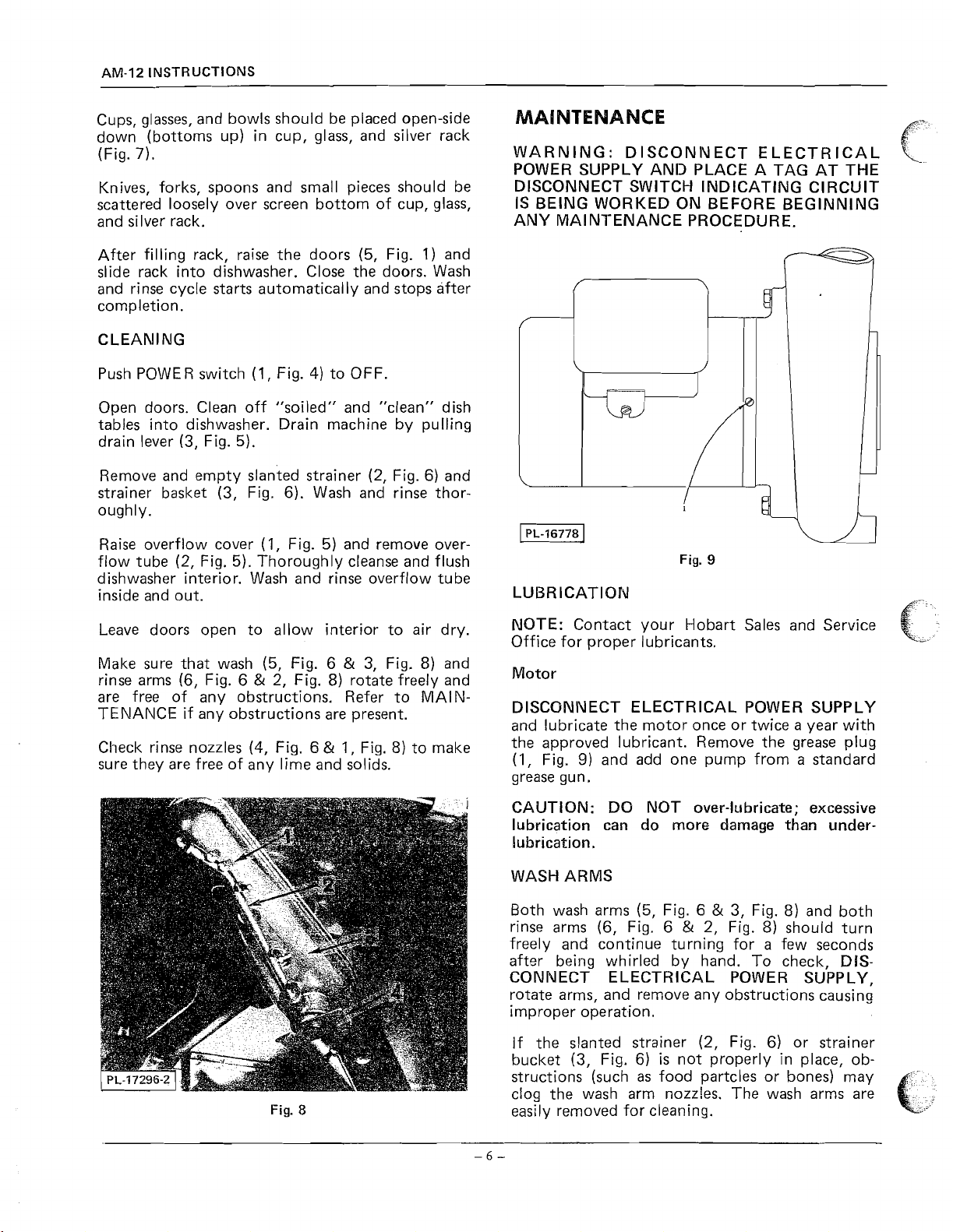
MAINTENANCE
WARNING: DISCONIVECT ELECTRICAL
POWER SUPPLY AND PLACE A TAG AT THE
DISCONNECT SWITCH INDICATING CIRCUIT
IS BEING WORKED ON BEFORE BEGINNING
ANY MAINTENANCE PROCEDURE.
Fig.
9
LUBRICATION
B
\
Leave doors open to allow interior to air dry.
Make sure that wash (5, Fig. 6
&
rinse arms (6, Fig. 6
2, Fig. 8) rotate freely and
&
3, Fig. 8) and
are free of any obstructions. Refer to MAINTENANCE if any obstructions are present.
Check rinse nozzles
(4,
Fig. 6 & 1, Fig. 8) to make
sure they are free of any lime and solids.
Fig.
8
NOTE: Contact your Hobart Sales and Service
Office for proper lubricants.
Motor
DISCONIVECT ELECTRICAL POWER SUPPLY
and lubricate the motor once or twice a year with
the approved lubricant. Remove the grease plug
(1,
Fig.
9)
and add one pump from a standard
grease gun.
:
CAUTION
lubrication can do more damage than
DO NOT over-lubricate; excessive
under-
lubrication.
WASH ARMS
Both wash arms
rinse arms (6, Fig. 6
(5,
Fig. 6 & 3, Fig. 8) and both
&
2, Fig.
8)
should turn
freely and continue turning for a few seconds
after being whirled by hand. To check, DISCONNECT ELECTRICAL POWER SUPPLY,
rotate arms, and remove any obstructions causing
improper operation.
If the slanted strainer
bucket (3, Fig. 6)
structions (such
as
(2,
Fig. 6) or strainer
is
not properly in place, ob-
food partcles or bones) may
clog the wash arm nozzles. The wash arms are
easily removed for cleaning.
Page 7
To remove the lower wash arm (5, Fig.
lift off the rinse arm
dowel (or end of punch) unscrew the rinse
bearing pin
arm. It
located on lower wash arm shaft.
The upper wash arm (3, Fig. 8)
unscrewing the hand knob
moving upper rinse arm and wash arm together.
Be careful not to drop these arms.
(7,
Fig. 6) and lift off lower wash
is
not necessary to remove the spacer
(6, Fig.
6),
is
(4,
Fig. 8) and re-
6),
first
then using a
arni
removed by
TROUBLESHOOTING
NOTE: If symptom persists after possible causes
have been checked-out, contact an authorized
Hobart Service Office.
-
SYMPTOM
POSSIBLE CAUSE:
Insufficient wash water due to drain obstruc-
'I.
tion preventing proper drain closing.
Dishes not clean
INSTRUCT1 ONS
4.
Excessively hard water.
5. lncorrect detergent for water conditions.
SYMPTOM
POSSIBLE CAUSE:
1. Dirty line strainer causing .reduced water flow.
Turn off water supply, remove strainer cap,
withdraw and clean screen. Reassemble.
2.
Low supply line pressure.
A
final rinse piping. Pressure should be 15-25
P.S.I. (20 P.S.I.
pressure, turn the
line) during final rinse.
pet cock be closed (perpendicular to the line)
by the end of the rinse cycle or damage to the
gauge may result.
SYMPTOM
POSSIBLE CAUSE:
-
Inadequate Rinse
pressure gauge (3, Fig. 1)
is
nominal). To check the rinse
petcock
It
is
-
Leaking valve (except solenoid type)
is
provided in the
90"
(parallel to the
important thst the
AM-12
2.
b
.
&.
2.
Worn or torn drain
water to drain.
3. Loss of water pressure due to pump obstructions.
DlSCONNECT ELECTRICAL POWER SUPPLY and drain tanks. Check for any obstruction
4.
lncorrect water temperature. Check circuit
breaker to electric heat supply, or main steam
valve. Make certain valve
Iiicorrect detergent dispensing. Contact your
5.
detergent representative
SYMPTOM
dishes
POSSIBLE CAUSE:
l mproperly loaded racks.
1.
2.
lncorrect rinse water temp. (min. 180"
3. Loss of water pressure due to pump obstruction.
DISCONNECT ELECTRICAL POWER SUPPLY and drain tanks. Check for any ob-
struction
at
the pump intake.
-
Spotting of silverware, glasses and
at
the pump intake.
"0"
ring allowing wash
is
completely open.
F.)
1. Foreign material preventing proper valve
operation.
NOTE:
tion when pipe compound or metal shavings
may lodge at the valve seat. Shut off supply
line. Unscrew and lift bonnet from valve body.
Clean valve and reassemble.
If a solenoid valve
2.
ommended that authorized Hobart Service
personnel be contacted.
SYMPTOM
POSSIBLE CAUSE:
1. The machine
safety device which shuts off the heat if water
level drops. Check for proper water level.
2.
Circuit breaker to heat system tripped.
3. Gas line closed.
4.
Steam valve not open completely.
SYMPTOM
POSSIBLE CAUSE:
1. Blown fuse or tripped circuit breaker
supply.
A
critical period
is
malfunctioning
-
No wash tank heat
is
equipped with a low water
-
No machine operation
is
soon after installa-
it
is
at
power
rec-
Page 8

Page
9
11
13
15
17
19
2 1
23
2
5
2 6
27
29
3
1
33
35
36
37
38
39
4
1
43
45
47
49
5
1
5 3
5 5
5 6
Description
Conduit (R.H. Controls)
Conduit (L.H. Controls)
Control Box
AM-12 Motor
AM-1 2A Motor
Motor Parts
Lower Wash Arm (Thrust Washer Type)
Lower Wash Arm (Ball Bearing Type)
Upper Wash Arm (Thrust Washer Type)
Upper Wash Arm (Ball Bearing Type
Upper Wash Arm (Ball Bearing Type
Outside Rinse Piping
lnside Rinse Piping
Inside Rinse Piping (Low Water Consumption)
Door Interlock
Door (Straight
Door (Corner)
Door Lift Unit (Straight
Door Lift Unit (Corner)
Strainers
Track Unit
Miscellaneous
Low Water Protection
Electric Heat
Gas Burner Unit
Flue
&
Igniter Control (Gas)
Steam Injector
Dish Racks
&
&
&
-
Thru)
Drain
Pump
Pump
-
Thru)
WIStationary Rinse)
WIRotating Rinse)
Page 9

REPLACEMENT PARTS
AM-12
ILLUS.
PL-16176
"*lo P-77657-39
**I2 FE-8-23
**I4 FE-8-11
PART
NO.
1 P-77657-38
2 FE-8-25
3 FE-8-11
4 FE-8-24
5 FE-8-11
**6 FE-8-25
*7 FE-8-33
**8 FE-8-11
*9 FE-8-12
*11 C-104192-9
*13 FE-8-31
*15 FE-8-12
CONDUIT
(R.H.
CORITROLS)
NAME
Conduit - 314" x 32" (Waterproof)
Connector 90' "Sealtite" (314" Male Thd. x 314" Flex. Cnd.)
314" Gasket Assy
Connector
314" Gasket Assy
Con~lector - 90' "Sealtite" (314" Male Thd. x 314" Flex. Cnd.)
Connector 90' "Sealtite" (1" Male Thd. x 1" Flex. Cnd.)
314" Gasket Assy ............................................. 1
1" Gasket Assy
Conduit
Conduit
Connector -Straight "Sealtite" (314" Male Thd. x 314" Flex. Cnd.)
Connector - Straight "Sealtite" (1" Male Thd. x
314" Gasket Assy
1"
*110-120
**200
.
.............................................
-
45' "Sealtite" (314" Male Thd. x 314" Flex. Cnd.)
.............................................
.
..............................................
-
314" x 10" (Waterproof)
-
1"
x 9-114" (Waterproof)
.............................................
Gasket Assy .............................................. 1
v.
V.
&
Above.
OF
PART AMT.
...................................
..................
..................
..................
.....................
...................................
..................................
................
1"
Flex. Cnd.)
..................
1
1
1
1
1
1
1
1
1
1
1
1
1
(i,
Page 10

Page 11

CONDUIT
(L.H. CONTROLS)
REPLACEMENT PARTS AM-12
I
LLUS
.
PL-16177
1
2
3
4
5
PART
NO
.
FE-8-11
'
FE-8-25
P-77657-1
FE-744
FE-7-32
C-119190-1
FE-8-11
FE-7-35
FE-8-11
FE-7-35
C-119190-2
FE-646
SC-21-23
WL-6-7
FE-7-32
FE-7-44
P-77657-5
FE-8-24
FE-8-11
FE-8-12
FE-8-32
C-104192-10
FE-14-37
FE-7-33
B-122915
B-119311-1
FE-7-33
FE-7-30
FE-7-33
B-119311-2
FE-8-12
FE-7-36
NAME
OF
PART AMT
314" Gasket Assy
Connector 90' "Sealtite" (314" Male Thd x 314" Flex Cnd.)
Conduit 314" x 18" (Waterproof) 1
Connector Straight "Sealtite" (314" Female Thd x 314" Flex Cnd.)
Connector -Straight (314" Male Thd x 314" Thinwall)
Conduit 314" Thinwall (Control Box to Coupling) 1
314" Gasket Assy
Ell 90' Short (314" Male Thd x 314" Thinwall) 1
314" Gasket Assy
Ell . 90' Short (314" Male Thd . x 314" Thinwall)
Conduit . 314" Thinwall (Control Box to Coupling)
Clamp
Mach . Screw . #lo-24 x 112" Rd Hd
Lock Washer
Connector . Straight (314" Male Thd . x 314" Thinwall)
Connector -Straight "Sealtite" (314" Female Thd . x 314" Flex . Cnd.)
Conduit
Connector . 45' "Sealtite" (314" Male Thd . x 314" Flex Cnd.)
Connector . 45' "Sealtite" (1" Male Thd
Conduit . 1"
Connector -Straight (1" Female Thd . x 1" Flex . Cnd.)
Connector -Straight (1" Male Thd
Clamp
Conduit . 1"
Connector -Straight (1" Male Thd . x 1" Thinwall)
Ell
Connector
Conduit
Ell
.
.
.
.
314" Conduit
.
314" Gasket Assy
Gasket Assy
1"
.
1"
.
90' x 1" Pulling
1" Gasket Assy
.
.
90' Short (1" Male Thd
.............................................
.
.
.
..................
...................................
.
.
.
..............
....................... .
.........................
.............................................
.
..........................
.............................................
..........................
.........................
..........................................
.
.
#
10 Medium
.......................................
.................................
.......................
..............
314" x 22" (Waterproof)
...................................
.
..................
.............................................
...............................................
x 24-112" (Waterproof)
1"
Flex Cnd.)
.
.
x
..................................
....................
.......................
Conduit
x 16" (Thinwall)
...........................................
1" Thinwall)
.....................................
..........................
.
x
..........................
...........................................
.
Straight (1" Male Thd . x 1" Thinwall)
1" x 4" (Thinwall) (Pulling Ell to Control Box)
..........................
......................
..............................................
.
x
1" Thinwall)
.............................
.
1
1
1
1
1
1
1
1
2
1
1
1
1
1
1
1
1
1
1
1
1
1
1
1
1
1
1
1
1
*110-120
**200
V
.
&
v
.
Above
.
Page 12
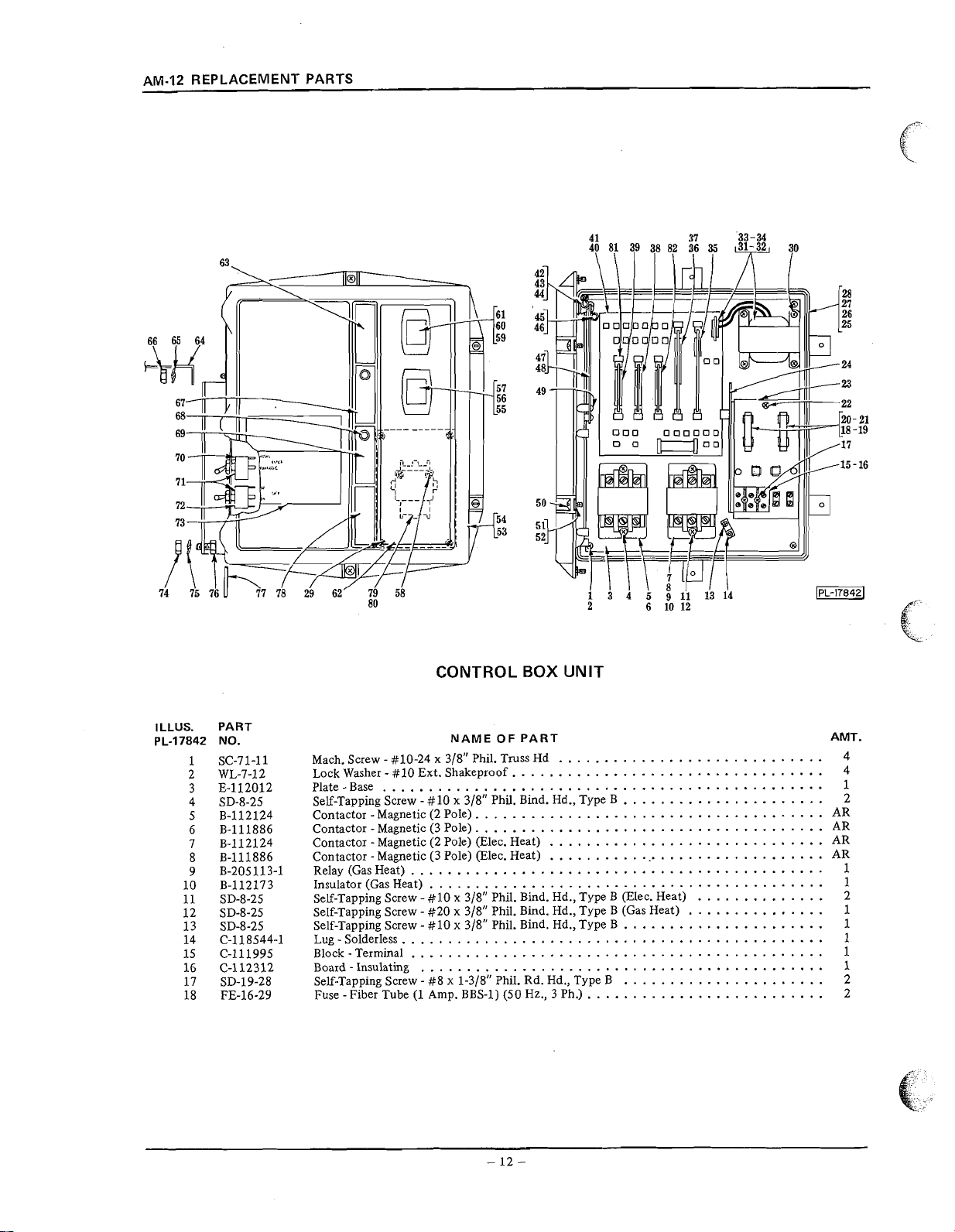
AM-12 REPLACEMENT PARTS
ILLUS. PART
PL-17842 NO.
1
SC-71-11
2 WL-7-12
3 E-112012
4 SD-8-25
5 B-112124
6 B-111886
7 B-112124
8 B-111886
9 B-205113-1
10 B-112173
11 SD-8-25
12 SD-8-25
13 SD-8-25
14 C-118544-1
15 C-111995
16 C-112312
17 SD-19-28
18 FE-16-29
CONTROL BOX UNIT
NAME OF PART AMT.
Mach. Screw - #lo-24 x 318" Phil. Truss Hd
Lock Washer - #10 Ext. Shakeproof.
Plate-Base
Self-Tapping Screw
Contactor - Magnetic (2 Pole)
Contactor
Contactor - Magnetic (2 Pole) (Elec. Heat)
Contactor
Relay (Gas Heat)
Insulator (Gas Heat)
Self-Tapping Screw
Self-Tapping Screw
Self-Tapping Screw - #10 x 318" Phil. Bind. Hd., Type B
Lug - Solderless
Block
Board - Insulating
Self-Tapping Screw - #8 x 1-318" Phil. Rd. Hd., Type B
Fuse
................................................
-
#
10 x 318" Phil. Bind. Hd., Type B
.
. . .
-
Magnetic (3 Pole)
-
Magnetic (3 Pole) (Elec. Heat)
. . . .
.
. . . . . . .
. . .
.
-
$10 x 318" Phil. Bind. Hd., Type B (Elec. Heat)
-
#20 x 318" Phil. Bind. Hd., Type B (Gas Heat)
-
. . . . .
Terminal
-
Fiber Tube (1 Amp. BBS-1) (SO Hz., 3 Ph.)
. . .
. . . .
. . . . . . . . . . . . . . . . . . . . .
.
.
.
. . .
.
.
. .
. .
. . . . . . . .
.
.
. . . . . . .
. . . . .
. . . . . . .
.
.
. . .
. . . . .
.
. . . .
. . . . . .
. .
.
. .
. . . .
. . . .
. .
.
.
.
. . .
.
. .
.
. .
.
. . . . . . . . . . . . .
. . . . . . . , . . . . . . . . . . . . . . .
.
.
. .
. . . . . . .
.
.
.
. . . . . .
. . . . .
.
. . . .
. . . . . . . .
. . . . . .
.
. .
. .
. . . . . . . . . .
. . . . . . . . . . .
. . . . . . . . .
. .
. .
.
..
.
. . . . . . .
. . .
. .
.
. .
.
. . . .
.
.
. . . . . . .
. . . . .
. . . .
. .
. . .
.
. . . . . .
. . . . .
. . . . . . . . . . . . .
. . .
. . . . .
.
.
. . . .
.
. . .
. . .
.
. .
. . . . . .
. .
. . . . . . . . . . .
. . . . . .
. . . . . . . .
. . . . . .
.
. . . . .
. . . . .
.
.
.
.
. . . . . .
. . . . . . . . . .
.
.
. . .
. . . . .
. . . . . . . . . .
. .
. . . . . . . . .
. . . . . . . . .
.
. . . . . .
. .
. . .
.
. .
. . . . .
. . . .
. .
.
. .
.
. . . .
. . . . . . . . .
.
. . . . . . . . . .
.
. . .
.
. . . . .
.
.
. .
.
.
.
.
.
.
.
4
4
1
2
AR
AR
AR
AR
1
1
2
1
1
1
1
1
2
2
Page 13

I
LLUS
.
PL-17842
19
20
2 1
22
23
24
"
"25
*:"6
*27
"28
29
30
31
PART
.
NO
FE-16-30
FE-19-48
FE-19-50
SD-8-18
C-118300
D-112059
E-119092-1
E-119138-1
E-119309
D-119182
SD-12-4
SD-8-25
C-111983-1
REPLACEMENT PARTS AM-12
CONTROL BOX UNIT (Cont.)
NAME OF PART AMT
Fuse . Fiber Tube (2 Amp . BBS-2) (50 Hz.. 1 Ph.)
Fuse -Fiber Tube (.8 Amp
Fuse -Fiber Tube (1.6 Amp
Self-Tapping Screw
Terminals
Insulator
Control Box (R.H. Controls)
Control Box
Control Box (R.H. Controls)
Control Box (L.H. Controls)
Self-Tapping Screw - $8-32 x 318" Phil . Truss Hd., Type 23
Self-Tapping Screw
Power Input Board Assy
Circuit)
Power Input Board Assy
3Ph.)
Power Input Board Assy
Power Input Board Assy
Power Supply Board
Timer Board Assy
Timer Board Assy
Motor Protector Board Assy
Temperature Control Board Assy
Master Board Assy
Master Board Assy
Retainer
Clamp-Wire
Self-Tapping Screw
Clamp-Wire
Self-Tapping Screw
Reed Mounting Board Assy
Switch-Reed
Self-Tapping Screw
Screw - Captive 4
Retainer
Spacer - Lid 4
Lid
Gasket
Start Switch Assy
Self-Tapping Screw
Lock Washer
Self-Tapping Screw
On/Off Switch Assy . (Maintained)
Self-Tapping Screw . #6-19 x 318" Phil . Pan Hd . "Plastite"
Lock Washer
Plate
Plate
Bracket -Control Box
Lock Washer
Full Nut
Plate
Solid State Pilot Light Assy . (Timed Fill)
Plate - Identification (Cycle) (Timed Fill)
Toggle Switch
Lock Washer
Toggle Switch
Plate-Data
Full Nut
Lock Washer
Cap Screw
Pin
Plate
Contactor (Soap Dispenser)
Insulator
Edge Guide
Timed Fill Board Assy
Wiring Harness (Not Shown)
Fuse (3 Amp., 32
&
Mounting Board Assy
-
Terminal Board
(L.H. Controls)
..................................................
...................................................
.
.
.
Clamp
.............................................
...............................................
...............................................
...............................................
..............................................
-
Captive Screw
.................................................
&
Gasket Assy . (Incls . item #54)
-
Control Box
.
.
#6 Ext . Shakeproof
-
.
.
.
#6 Ext . Shakeproof
Base (Dispenser Contactor)
Identification (Power)
-
114" Light
.
114"-20 Hex Fin
Identification (Fill) (Timed Fill)
&
Label Assy . (Cycle)
-
112" Int . Shakeproof
&
Label Assy . (On/Off)
................................................
.
5116"-18 Hex Fin
-
511 6" Light
.
5116"-18 x 314" Hex Hd . (Control Box to Support)
.
Control Box & Lid
.
Identification (Blank)
..................................................
-
P.C. Board
V.)
.
BBS.8) (60'Hz., 3 Ph.)
.
-
BBS.1.6) (60 Hz., 1 Ph.)
#8 x 318" Phil . Bind . Hd., Type B
...................................
........................................
.............................
......................................
......................................
......................................
.
#
10 x 318" Phil . Bind . Hd., Type B
.
(110-120
.
(200-230
.
(115
.
(220
Assy
........................................
(ML-18500 & ML-18501)
(ML-31819 & ML-31820)
V.,
60 Hz., 1 Ph.) (200-230
V.,
60 Hz., 3 Ph
V.,
50 Hz., 1 Ph.) (220
V.,
50 Hz.. 3 Ph
......................................
...................................
.
(ML-18500 & ML-18501)
.
(ML-31819 & ML-31820)
.
#8 x 318" Phil . Bind . Hd., Type B
-
#8-32 x 112'' Phil . Truss Hd., Type 23
.
(Incls . item #48)
.
#8-32 x 318" Phil . Truss Hd., Type 23
........................................
.................................
..........................................
(Momentary) (Timed Fill)
.
#6-19 x 318" Phil . Pan Hd . "Plastite"
..................................
-
#10 x 318" Phil . Bind . Hd., Type B
...................................
..................................
...................................
......................................
..........................................
........................................
.......................................
................................
.................................
..................................
................................
......................................
.......................................
.........................................
......................................
.......................................
.........................................
..........................................
......................................
(Use in Power Input Board) 1
..........................
.........................
.......................
.......................
;
........
.....................
.....................
V.,
.
.
W/Pilot Circuit) (400-460
V.,
..
W/Pilot Circuit) (380
50 Hz., 1 Ph
60 Hz., 1 Ph
..
V.,
.
.
W/Pilot
V.,
60 Hz.,
W/Pilot Circuit)
50 Hz., 3Ph.)
...
....
.............................
.............................
.............................
............................
.......................
....................
............................
....................
............................
.....................
......................
.....................
...............................
...............................
..................
..........................
:
10
.
2
2
2
1
1
1
1
1
1
1
4
4
1
1
1
1
1
1
1
1
1
1
1
1
1
1
2
2
1
2
2
4
1
1
1
2
2
2
1
2
2
1
1
1
2
2
1
1
1
1
2
1
1
2
2
2
3
1
1
1
1
1
*110-120
**200
V
.
&
v
.
Above
.
-
13
-
Page 14
Page 15
REPLACEMENT PARTS AM-12
PART
.
NO
NS-246
WL-6-32
WS-21-1
D-118968
D-121567-2
KW-3-3
A-104329
D-67500-7
FP-64-15
ML-18491
SC41-11
WL-6-22
B-119265
E-118961
C-119054
C-119050
C-118960
WL-6-22
SC-41-11
SC41-11
WL-6-22
WS-17-8
SC41-5
WL-6-17
WS-348
B-119051
B-119299-1
B-119299-2
B-119299-3
B-1192994
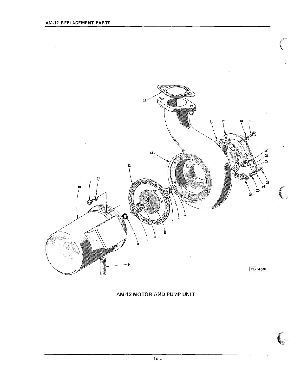
AM-12 MOTOR
PRIOR TO SERIAL NO . 23-028-320 (AM-12)
NAME OF PART AMT
Acorn Nut . 7116"-20
Lock Washer . 7/16" Light
Washer
...................................................
Impeller (60 Hz.)
Impeller (50 Hz.).
Key . #404 Woodruff
Shaft Seal Assy
-0"Ring
Nipple . 318" x 2-114" Lg . (S.T.O.E.)
Motor (Give Electrical Spec.)
Cap Screw . 5/16"-18 x 314" Hex Hd
Lock Washer
Gasket Kit (Motor to Pump) (One Set consists of: 1 Blue
and 1 Yellow
Shell-Pump
Gasket . Pump Discharge
Gasket . Pump Intake
Shroud . Pump Intake
Lock Washer . 5/16" Light
Cap Screw 5116"-18 x 314" Hex Hd 4
Cap Screw
Lock Washer
Washer
Cap Screw
Lock Washer
Washer
Gasket
AM-12 Motor & Impeller Assy . (60 Hz., 1 Ph.) (Incls . items #1,2,3,4,6,7,
AM-12 Motor & Impeller Assy . (60 Hz., 3 Ph.) (Incls . items
AM-12 Motor & Impeller Assy . (50 Hz., 1 Ph.) (Incls . items #1,2, 3,5,6,7, 8 & 10)
AM-12 Motor & Impeller Assy . (50 Hz., 3 Ph.) (Incls . items #l,2, 3,5,6,7, 8 & 10)
.................................................
.
5/16" Light
(.020" Thk.))
...............................................
.
.
5116"-18 x 314" Hex Hd
.
5/16" Light
...................................................
.
114"-20 x 518" Hex Hd
.
...................................................
.
Pump Drain Hole
........................................
.......................................
.............................................
............................................
..........................................
..
518"
..........................................
.......................................
.......................................
........................................
..........................................
..........................................
.......................................
.......................................
114" Medium
........................................
AND PUMP UNIT
12-052-786 (AM-1 2)
12-052-922 (AM-1 2C)
..................................
......................................
.................................
(.005" Thk.); 1 Brown (.OIOn Thk.);
.................................
.................................
..................................
......................................
8
&
10)
#I,
2,3,4,6,7, 8 & 10)
.....
.....
.....
.....
1
Set
.
1
1
1
1
1
1
1
1
1
1
6
6
1
1
1
1
4
2
2
2
2
2
2
1
1
1
1
1
*Select gasket to obtain . 005" to . 015" clearance between pump and impeller
.
Page 16
SlkiVd lN3VU33VId3tl ZL-VUV
Page 17

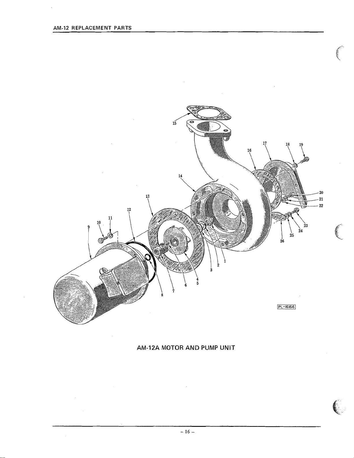
AM-12A MOTOR AND PUMP UNIT
FIRST SERIAL NO . 23-028-320 (AM-12)
12-052-786 (AM-1 2)
12-052-922 (AM-IZC)
REPLACEMENT PARTS AM-12
l-
\
ILLUS . PART
PL-16166 NO
1
2 WL-6-32
3 WS-21-1
4 D-118968
5 D-121567-2
6 KW-3-3
7 A-104329
8 D-67500-7
9 ML-34217
10 SC-41-29
11 WL-6-27
12 D-67500-97
*13 B-277836
14 E-276281
15 C-119054
16 C-119050
17 C-118960
18 WL-6-22
19
20 SC-41-11
21 WL-6-22
22 WS-17-8
23 SC-41-5
24 WL-6-17
25 WS-3-48
26 B-119051
.
NS-24-6
SC-41-11
B-277786-1
B-277786-2
B-277786-3
B-277786-4
NAME
OF
PART AMT .
Acorn Nut . 7116"-20
Lock Washer . 7/16" Light
Washer
...................................................
Impeller (60 Hz.)
Impeller (50 Hz.)
Key . #404 Woodruff
Shaft Seal Assy
"0"Ring
Motor (Give Elec
Cap Screw 318"-16 x 718" Hex Hd
Lock Washer
"0"Ring
Shim Kit (Motor to Pump) (One Set consists of: 1 Blue (.005" Thk.); 1 Brown (.010" Thk.);
and 1 Yellow
Shell-Pump
Gasket -Pump Discharge
Gasket . Pump Intake
Shroud -Pump Intake
Lock Washer
Cap Screw 5116"-18 x 314" Hex Hd 4
Cap Screw
Lock Washer
Washer
Cap Screw
Lock Washer
Washer
Gasket
AM-12A Motor & Impeller Assy . (60 Hz.. 1 Ph.) (Incls . items #1.2.3.4.6,7.8. 9 & 12)
AM-12A Motor &Impeller Assy
AM-12A Motor & Impeller Assy . (50 Hz., 1 Ph.) (Incls . items #1.2.3.5.6,7.8. 9 & 12)
AM-12A Motor &Impeller Assy . (50 Hz., 3 Ph.) (Incls . items #1.2.3.5.6.7.8,
.................................................
.
.
.................................................
(.020" Thk.))
.
511 6" Light
.
.
5116"-18 x 314" Hex Hd
-5116" Light
..................................................
.
114"-20 x 518" Hex Hd
.
...................................................
-Pump Drain Hole
..........................................
.......................................
.............................................
..............................................
..........................................
..
518"
..........................................
.
Spec.)
........................................
..................................
318" Light
........................................
.......................................
...............................................
........................................
........................................
..........................................
........................................
.................................
.................................
.......................................
..................................
114" Medium
......................................
........................................
...
.
(60 Hz., 3 Ph.) (Incls. items #1.2. 3.4,6,7.8. 9 & 12)
9
...
...
&
12)
...
1 Set
1
1
1
1
1
1
1
1
1
2
2
1
1
1
1
1
4
2
2
2
2
2
2
1
1
1
1
1
*Select shims to obtain . 005" to . 012" clearance between pump and impeller
.
Page 18

Page 19

REPLACEMENT PARTS AM-12
MOTOR
(AM-1 2A = M L-34217)
(AM-1 2
PART
NO
.
C-119858-2 Switch Starting (Stationary Part) 1
SC-949
D-114379-3 Bracket
D-114379-2 Bracket
D-111493-1 Fan . Ventilating
R-77067 Cover -Motor End
SC-9-65
SL-24 Loading Spring
RR4-17 Retaining Ring
BB-20-18 Ball Bearing
SC-81-76 Mach Screw #lo-24 x 7" Rd Hd 4
WL-8-13 Lock Washer #10 Int Shakeproof 4
D-113403 Box
SD-15-27
WL-7-12 Lock Washer #10 Ext Shakeproof 2
SD-1245
M-60395 Grommet
M-79118 Bushing
M-80369 Bushing . Snap (Field Ring)
SD-1245 Self-Tapping Screw #8-32 x 5/16" Pan Hd., Type 23 2
C-113405 Cover -Terminal Box
B-114811 Gasket . Terminal Box Cover
C-113417 Connector Block Assy
C-113552 Terminal Block Base Assy
D-65477-147-1 Stator Assy (100-1 15 V.1200.230 V 60 Hz.) 1
D-65477-147-2 Stator Assy (110-120 V.1220.240 V 50 Hz.) 1
D-65478-110-1 Stator Assy (200-230 V./400-460 V 60 Hz.) 1
D-65478-112-1 Stator Assy (200-240 V./346-415 V 50 HZ.) 1
C-22275-208 Rotor Assy
C-22275-207 Rotor Assy (100-120 V./200.240 V 50 Hz.)
C-15747-288 Rotor Assy (200-230 V./400.460 V 60 Hz.) (200-240 V.1346.415 V 50 Hz.) 1
B-104725 Capacitor Cover
D-704876 Capacitor
M-89258 Retainer . Capacitor
SD-15-3 Self-Tapping Screw #lo-24 x 114" Pan Hd "Taptite" 2
WS-2-15 Washer (Shims screw to prevent bottoming) 2
BB-20-18 Ball Bearing
E-121191-1 Bracket Bearing (Pump End) (60 Hz.) (AM-12A Only) 1
E-121191-2 Bracket Bearing (Pump End) (50 Hz.) (AM-1 2A Only) 1
E-118969-1 Bracket Bearing (Pump End) (60 Hz.) (AM-12 Only) 1
E-118969-2 Bracket Bearing (Pump End) (50 Hz.) (AM-1 2 Only) 1
B-118070-1
.
.
Screw . #6-32 x 318" Rd . Hd
Mach
.
Bearing (Fan End)
.
Bearing (Fan End)
.............................................
.
Screw . #8-32 x 1/4" Rd . Hd
Mach
............................................
.
N.D. #S-17
..............................................
.
N.D. #77503
.
.
.
.
Terminal
Self-Tapping Screw
Self-Tapping Screw
..............................................
.
.
.
.................................................
.
Snap (Field Ring)
.
. ..
.
.
.
.
(1
00-1 20 V./200.230 V 60 HZ.) 1
.
.
&
Insulator Assy
................................................
.
.
N.D. #77503
.
.
.
Plug (Not Shown) (Use with items
.
NAME
......................................
......................................
......................................
.......................................
.
.
#lo-24 x 5/16" Pan Hd . "Taptite"
.
#8-32 x 5/16" Pan Hd., Type 23
.......................................
.......................................
..........................................
......................................
..........................................
........................................
...........................................
.......................................
UNIT
=
ML-18491)
OF
PART AMT
...................................
..................................
..................................
..................................
..................................
......................
..................................
.......................
.......................
............................
..
..
..
..
..
..
............................
............................
............................
............................
............................
..
........
...................................
.
.......................
.............................
......................
......................
.......................
#38,39, 40 & 41)
.......................
........................
.
2
1
1
1
1
2
1
1
1
1
2
2
1
1
1
1
1
1
1
1
1
1
1
1
1
*1 Phase
**3 Phase
.
.
Page 20

LNUV HSVM U3MO1
llNn
Page 21

REPLACEMENT PARTS AM-12
ILLUS . PART
PL-16196
NO
.
1 D-119032
2 D-67500-57
3 SC-41-30
4 WL-6-28
5 E-118973-2
6 B-119034
7 B-119229
8 C-119222
9 B-119227
10 D-119198
11 WL-6-7
12 SC-21-21
13 M-24160
14 M-22731-3
15 M-74046
16 R-89159
17 C-119087
18 M-21110
19 V-21137
20 SC-21-14
21 D-67500-57
22 WL-6-1
23 SC-50-26
24 R-89158
C-119113
LOWER WASH ARM
UNIT
(THRUST WASHER TYPE)
NAME
OF
PART
Tube-Wash
"0"Ring
Cap Screw 318"-16 x 1" Hex Hd
Lock Washer
Tee . Lower Wash
Shaft . Lower Wash Arm
Spring . Compression
HubAssy
Washer . Thrust
Wash Arm & Hub Assy . (Incls . items #8,9, 11 & 12)
Lock Washer #10 Medium
Mach Screw #lo-24 x 114" Rd Hd
Rinse Arm Bearing Pin & Thrust Washer Assy
Nozzle Rinse
Plug Rinse Arm
Arm
Rinse Arm Body Assy . (Incls . item #18)
Bearing . Rinse Arm
Plate . Pivot Bearing
Mach Screw #8-32 x 318" Rd Hd
"0"Ring
Lock Washer #8 Light
Set Screw #lo-24 x 318" Sq Hd., Cup Pt
Arm Outside Rinse
Lower Rinse Arm Assy
................................................
.................................................
.
.
318" Medium
...................................
......................................
............................................
........................................
..........................................
.................................................
..............................................
.
.
.
.......................................
.
.................................
............................
.
.
.
Inside Rinse
..............................................
..............................................
............................................
...............................
...........................................
...........................................
.
.
.
..................................
.................................................
.
.
.
.........................................
.
..............................
...........................................
.
(Incls . items #14 thru 20,22, 23 & 24)
........................
..................
AMT
1
.
Page 22

Page 23

REPLACEMENT PARTS AM-12
LOWER WASH ARM
UNIT
(BALL BEARING TYPE)
ILLUS . PART
PL-17806-1
i
:
\
.
NO
.
1
D-119032
D-67500-57
2
3 SC-41-30
WC6-28
4
5 E-118973-2
6 B-119034
7 B-286944
8 D-286948
9 BA-2-40
10 D-67500-19
11 C-286947
12 D-287987
13 WL-6-7
14 SC-21-23
15 B-286946
16 B-122440
17 M-22731-3
18 C-122443-2
19 D-122633
20 V-21137
21 SC-21-14
22 D-67500-57
23 WL-6-1
SC-110-44
24
25 C-122442-2
D-122635-2
Tube-Wash
"0"Ring
Cap
Screw . 318"-16
Lock Washer
Tee
.
Shaft
Spacer
Hub
.
Ball
uO"Ring
Retainer
Wash Arm &Hub Assy . (Incls . items #8, 9.10.11. 13 & 14)
Lock Washer
Mach
Bearing Pin & Washer Assy
Pug-RinseArm
Nozzle . Rinse
Arm
Body
Plate
Mach . Screw . #8-32 x 318" Rd . Hd
"OWRing
Lock Washer . #8 Light
Set Screw
Arm
Lower Rinse Arm Assy . (Incls . items #16 thru 21.23, 24 & 25)
................................................
.................................................
.
Lower Wash
.
318'' Medium
............................................
Lower Wash Arm
...................................................
....................................................
114" Dia
.............................................
.................................................
.
Ball
..............................................
.
#
.
Screw
10 Medium
.
#
10-24 x 112" Rd . Hd
.............................................
..............................................
.
Rinse (4 Nozzle Holes)
.
Lower Rinse Arm
.
Pivot Bearing
.................................................
.
5116"-18 x 318" Soc . Hdls., Cone Pt
.
Rinse
(5
Nozzle Holes)
x
1"
Hex Hd
NAME
OF
PART AMT
...................................
......................................
........................................
...................
.......................................
.................................
.
:
.....................................
......................................
........................................
...........................................
..................................
.........................................
...........................
......................................
..................
.
1
1
2
2
1
1
1
1
13
1
1
1
2
2
1
2
9
1
1
1
4
1
4
2
1
1
Page 24

H3ddfl
HSVM
WtJV
LINT\
(MA1 kl3HSWM 1SnklHl)
Page 25

REPLACEMENT PARTS AM-12
PART
NO
.
SC-41-9
WL-6-22
E-118972-2
C-119033
C-119222
B-119227
D-119198
WL-6-7
SC-21-21
C-118978
R-14524
P-103952
UPPER
Cap Screw . 5/16"-18 x 112" Hex Hd
Lock Washer
.
Upper Wash
Ell
Shaft . Upper Wash Arm
HubAssy
Washer-Thrust
Wash Arm & Hub Assy . (Incls . items #5.6. 8 & 9)
Lock Washer . #10 Medium
Mach
Nut -Wash Arm
Core . Rinse Nozzle
Top . Rinse Nozzle
.
5/16" Light
.............................................
.................................................
............................................
.
Screw . #lo-24 x 114" Rd . Hd
.............................................
...........................................
............................................
WASH ARM
(THRUST WASHER TYPE)
NAME
OF
PART AMT
.................................
.......................................
.........................................
........................................
.................................
UNIT
.........................
.
2
2
1
1
1
1
1
2
2
1
1
1
Page 26

AM-12 REPLACEMENT PARTS
ILLUS. PART
PL-17075-1 NO.
1 SC-41-9
2 WL-6-22
3 E-118972-2
4 C-119033
5 D-286948
6 D-67500-19
7 BA-2-40
8 C-286947
9 D-286943
10 WL-6-7
11 SC-21-23
12 C-118978
13 R-14524
14 P-103952
UPPER
(WITH STATIONARY RINSE)
Cap Screw - 5116"-18 x 112" Hex Hd
Lock Washer - 5/16" Light
Ell - Upper Wash
Shaft - Upper Wash Arm.
Hub
....................................................
"0"Ring
Ball - 1/4" Dia
Retainer - Ball
Washer Arm & Hub Assy. (Incls. itmes #5,6,7,8, 10 & 11)
Lock Washer - #10 Medium
Mach. Screw
Nut-WashArm
Core - Rinse Nozzle
Top - Rinse Nozzle
. .
. . . . . . . .
.................................................
.
. . . . . . . . .
.
. . . .
-
#
10-24 x 1/2" Rd. Hd
.............................................
. . . . .
. . . . . .
WASH
(BALL BEARING TYPE)
NAME OF PART
.
. .
. . . . . . . . . . . . . . . . . . .
. . . .
.
.
. . .
. . .
. .
ARM
UNIT
.
. . . . .
. .
. . . . . . . . . . . . . . .
. .
. . . . . . . . . .
. . . .
. . . . . .
. .
. . . . . . . . . . . . . . . . . . . . . . . . . . . . . . . .
. . . . . .
.
. . . . .
. .
.
.
. .
. . . . . . . . . . . .
. . . . . .
. .
. . . . .
. . . . . . . . . . .
. . . . . . . . .
.
.
.
. . .
. . . . . . . . . . . . . . . . .
. . . . . . . . . . .
. .
. . . . . .
. . . . . . .
. . .
. .
.
.
. .
. . . . . . . . . . . . . .
.
. . . . .
. . . . .
.
. . . . . .
. . . . . . .
. . . . . . .
. . . . .
. .
. .
.
. . .
.
.
. .
. . .
. . . . . . . . . . . .
. . .
. . . . . . . . .
.
. . . . .
. . . .
.
. . .
. . . . . . . . .
. . .
. . . . . . .
. . . . .
. .
. . . .
. .
.
. . . .
. . . .
. .
.
.
. .
.
.
.
.
.
AMT.
2
2
1
1
1
1
13
Page 27

REPLACEMENT PARTS AM-12
-1
@-
2
3
.
ILLUS
.
PL-17106-2
PART
1 SC-41-9
2 WL-6-22
3 E-118972-2
4
B-122437
5 D-286948
6 D-67500-19
7 BA-240
8 C-286947
9 D-287987
10 WL-6-7
11 SC-21-23
12 B-122438
13 D-122401
1.4 C-287908
15 B-122440
16 SC-11044
17 B-122632
18 C-122445
19 RR-11-3
20 M-22731-3
21 C-287913
C-287932-2
NO
UPPER
WASH
ARM
UNIT
(BALL BEARING TYPE)
(WITH
.
Cap Screw . 5/16"-18 x 112" Hex Hd
Lock Washer
.
Upper Wash
Ell
Shaft
Hub
"0"Ring
Ball . 1/4" Dia
Retainer
Washer Arm & Hub Assy . (Incls . items #5.6.7.8. 10 & 11)
Lock Washer . #10 Medium
Mach
Upper Rinse Shaft Assy
Hub-RinseArm
Arm
Plug . Rinse Arm
Set Screw 5/16"-18 x 3/8" Soc Hdls., Cone Pt "Nylok"
Washer -Thrust
Handle
Retaining Ring
Nozzle
Arm
Rinse Arm Assy
.
5/16" Light
.............................................
.
Upper Wash Arm
....................................................
.................................................
..............................................
.
Ball
..............................................
.
Screw . #lo-24 x 112" Rd . Hd
.............................................
.
Outside Rinse (5 Nozzle Holes)
.............................................
.
..............................................
...................................................
..............................................
.
Rinse
-Inside Rinse (6 Nozzle Holes)
..............................................
.
(Incls . items #12 thru 21)
ROTATING RINSE)
NAME
OF
PART AMT
.................................
.......................................
.........................................
....................
.......................................
.................................
.........................................
.................................
.
.
.....................
..................................
.............................
2
2
1
1
1
1
1
3
1
1
2
2
1
1
1
2
2
1
1
1
11
1
1
.
Page 28

Page 29

OUTSIDE RINSE PlPllVG UNIT
REPLACEMENT PARTS AM-12
PART
NO
.
C-119290
A-119127
SC41-13
WL-6-22
D-67500-12
SC41-16
WS-17-8
SC41-5
WS-3-48
WL-6-17
NS-15-1
D-119292
D-67500-12
P-63262-26
WL-6-22
NS-15-11
A-106468-5
P-86218
C-119066
A-102516
M-82231
A-102517
M-82236
M-82238
D-67500-59
FE-8-10
FE-6-45
D-119004-2
FE-645
FE-76
P-6819068
FE-7-3
FE-8-10
C-277915
NS-15-11
WL-6-22
SC41-15
C-276678
B-277 11 2
B-118270
C-119291
M-74338
A-104729
*M-74343
B-112062-1
NAME OF PART AMT
Connector Assy . (Rinse to Vacuum Breaker)
.
118" Sq
.
Plug
Cap Screw
Lock Washer
"0"Ring
Cap Screw . 5/16"-18 x 1-318" Hex Hd
Washer
Cap Screw
Washer
Lock Washer
Full Nut
Bracket
"0"Ring
Flange & Nipple Assy
Lock Washer
Full Nut . 5116"-18 Hex Fin
Solenoid Valve
Pet Cock
.....................................................
Tee
Line Strainer (314") (Incls . items #21,22, 23, 24 & 25)
Screen
.
Plate
Clamp
Thumb Screw
"0"
Ring (314" Line Strainer)
112" Gasket Assy
Connector
Conduit
Connector
Connector . Straight "Sealtite" (112" Female Thd
Conduit . 3/23'' x 25" (Waterproof)
Connector . 90' "Sealtite" (112" Male Thd . x 318" Flex Cnd.)
112" Gasket Assy
Gauge -Water Pressure
Full Nut . 5/16"-18 Hex Fin
Lock Washer
Cap Screw . 5116"-18 x 1-114" Hex Hd
Connector Assy . (Vacuum Breaker to Solenoid)
Vacuum Breaker . 314" (Incls . item #40)
Float Assy & Bonnet Gasket Service Kit (Vacuum Breaker)
Connector Assy . (Vacuum Breaker to Solenoid) 1
Vacuum Breaker
Cap
.
Vacuum Breaker
Vacuum Breaker Float
.
Solenoid (1 15 V.)
Coil
Hd . Pipe
.
5116"-18 x 1" Hex Hd
.
5/16" Light
.................................................
..................................................
.
114"-20 x 518" Hex Hd
..................................................
.
114" Medium
.
114"-20 Hex Fin
.
Outside Rinse Piping
.................................................
.
5/16" Light
.
.
114"
(314" Line Strainer)
Seal (314" Line Strainer)
(314" Line Strainer)
......'.........................................
.
Straight (112" Male Thd . x 112" Thinwall)
.
112" (Low Water Protection Box to Coupling)
.
Straight (112" Male Thd . x 112" Thinwall)
.
5/16" Light
.
.........................................
...................................
.......................................
......................................
.......................................
.....................................
..........................................
.......................................
.......................................
314" (1 15
V.,
50160
..............................................
.......................................
....................................
.......................................
.....................................
.............................................
...................................
.............................................
..........................................
......................................
.......................................
.
314" (Incls . item #43)
..........................................
&
Seal Assy
.........................................
.............................
................................
..................................
Hz.)
..............................
......................
.......................
......................
.......................
.
x
318" Flex . Cnd.)
.
..............
..................
................................
...........................
...............................
....................
...........................
...............................
..................................
.
'
1
1
2
2
1
1
1
2
2
2
2
1
1
1
1
1
1
1
1
1
1
1
1
1
1
1
1
1
1
1
1
1
1
1
1
1
1
1
1
1
1
1
1
1
*Use with SLOAN Vacuum Breaker
**Use with WATTS Vacuum Breaker
.
.
Page 30

SltlVd lN3VU33Vld3tl ZL-WV
Page 31

ZL-INV SlHVd .LN3VU33Vld3H
srni
I
T
Z
E
L
OT
ZT
E
T
LT
OZ
IHV~
'ON
1-9LOLL-ld
ZZ-12-3s
L-9-TM
P668IT-'3
OLO6IT-3 P
IT-ST-SN S
ZZ-9-?M 9
ZZ-9-TM 8
OPTV3S 6
PZSPT-ZI
ZS6EOT-d 11
01-TV3S
ZZ-9-TM
6-OOSL9-a PT
PE89LZ-a ST
7-S6681T-3
6-OOSL9-a 81
ZZ-9-?M 67
01-IV3S
~301
ZT-OOSL9-a
ZT-OOSL9-a 91
"0.9
aro3
do^
de3
"O,,
"O,,
"O,,
-
j~oddns
-
JnN Ttnd
%ux
Ma13S de3
-
-
-
~u!ZI
2ux
ZU!~
Mal3S de3
-
Mal3S 'Y3eH
-
IaqseM
-
ra9seM Wo'I
-
WseM Vo?
-
-
Mal3S
-
IazlseM Wo?
-
IaqseM V0-I
-
/S
rol3auuo3 asu!x
T
OT#
Lssv ad!d as48 ~addn
,,9T/S
aIzzoN asy
a1zzoN asux
9
Lssv ropauuo3 asu!X
'
mn!paK
ad!d asurx raddn
u!d XaH 81-,,9T/S
lzl8!1,,9
l@!?
l9%!1,,9 I/S
Lssv alue~d
lzl211 ,,9T/S
dO
3WVN
PH 'PZI ,,8/£ x PZ-OT#
PH XaH ,,8/S x 81-,,9T/S
.
PH XaH ,,8/S x 81-,,9I/S
PH XaH ,,8/S x 81-,,91/S
IHVd
.................................
......................................
.........................................
.......................................
......................................
.......................................
.................................................
.......................................
.................................
...........................................
............................................
................................
.......................................
.................................................
.....................................
.................................................
...........................................
.................................................
.......................................
.................................
Page 32

Page 33

INSIDE RllUSE PIPING UNIT
(LOW WATER CONSUMPTION)
REPLACEMENT PARTS AM-12
ILLUS. PART
PL-17807-1 NO.
1
D-67500-12
2 WL-6-22
3 SC-41-10
4 D-287947
5 SC-41-9
6 WL-6-22
7 D-67500-9
8 D-276834
9 D-67500-9
10 WL-6-22
11 SC-41-9
NAME OF PART AMT.
"0"Ring
Lockwasher-5/16"Light
Cap Screw
Upper Rinse Pipe Assy
Cap Screw - 5/16"-18 x 112" Hex
Lock Washer
"0"Ring
Rinse Connector
"0"Ring
Lock Washer - 5/16" Light
Cap Screw
.................................................
-
5116"-18 x 518" Hex Hd
-
5/16" Light
. . . . . . . . . . . .
. .
.
. .
.
.
.................................................
&
Flange Assy
.................................................
.
-
5/16"-18 x 112" Hex Hd
.
. . . .
. . .
.
. . . .
.
..
. . .
.
.
.
.
. . . . . . . . . . . . . . . . . . . . . . . . . . . . .
Hd
.
.
. . . . . . . . . . . . . . . . . . . . .
. . .
. . . . . . . . . . .
. . . .
. . . . .
. .
. . . . . . . . . . .
. . . . . . . . . . . . . . . . . . . . .
.
.
. .
.
. .
. . . . . .
. . .
.
. .
.
. .
. . . .
.
.
.
. . . . . . . . . .
. . .
.
. . . . . . . . . . . .
. . .
.
.
. . . . . . . . . .
. . . . . . . . . . . . . . .
.
.
. . . . .
. .
.
.
.
..
. . . .
.
. .
. . .
.
. .
.
.
. . . . .
.
. .
.
.
. .
. .
. .
.
.
.
.
.
. .
1
.
2
.
2
.
1
.
2
2
1
1
1
.
2
2
Page 34

Page 35

DOOR INTERLOCK UNIT
REPLACEMENT PARTS AM-12
PART
NO
.
13-119062
VJL-6-17
NS-15-1
FE-8-10
FE-6-45
D-119004-1
B-119065-1
FE-6-45
FE-7-6
P-68190-5
FE-7-1
WL-6-7
WS-19-6
SC-21-34
D-288490
SC-2 1-25
B-288455
WS-29-10
WL-6-7
NS-11-18
B-106803
B-288456
SD-25 -1 2
B-119075
C-119057
B-119300
SD-12-35
NAME OF PART AMT
Retainer . Conduit
Lock Washer
Full Nut
112" Gasket Assy
Connector . Straight (112" Male Thd
Conduit . 112" Thinwall (Heat Box to Coupling)
Bracket
Connector
Connector
Conduit . 318" x 11" (N"v'terproof)
Connector
Lock Washer
Washer
Mach
Housing
Mach
Spacer
Washer
Lock Washer
Mach
Gasket
Interlock Switch
Self-Tapping Screw
Retainer
Magnet -Door Interlock Switch
Gasket
Self-Tapping Screw
.
114"-20 Hex Fin
.
Conduit
.
.
.
...................................................
.
Screw . #lo-32 x 1-314" Rd . Hd
.
Interlock Switch
.
Screw
&
Insert Assy
...................................................
.
Nut . #lo-24 Hex
.
Interlock Switch
.
Magnet
.
Magnet Retainer
............................................
.
114'' Medium
......................................
.......................................
.............................................
.
x
1/2" Thinwall)
.......................
...........................
............................................
Straight (112" Male Thd . x 112" Thinwall)
Straight "Sealtite" (112" Male Thd . x 318'' Flex . Cnd.)
.......................
................
...................................
Straight "Sealtite" (112'' Male Thd . x 318'' Flex . Cnd.)
.
#10 Medium
.......................................
................
................................
.......................................
.
#
10-24 x 314" Rd . Hd
.................................
...........................................
.
#
10 Medium
.......................................
........................................
........................................
&
Cover Assy
.
#8-18 x 112" Phil . Pan Hd . "Shakeproof"
.....................................
..................
............................................
....................................
........................................
.
#8-32 x 1/2" Phil . Pan Hd., Type 23
.....................
.
1
1
1
1
1
1
1
1
1
1
1
2
2
2
1
2
1
2
2
2
1
1
2
1
1
1
2
Page 36

AM-12 REPLACEMENT PARTS
PART
NO.
E-119006-2
B-119103
PC-5-2
C-119236
D-112378-23
E-119006-1
D-119133
NS-18-6
WS-17-8
C-119168
SC-21-23
WL-6 -7
C-119086
B-119007
DOOR
(STRAIGHT THRU INSTALLATION)
NAME
Door
-
Counterbalanced (L.H.) .
-
Flat Hd
Rivet
Cotter Pin
Latch - Inspection Door
Guide-Door
Door - Counterbalanced (R.H.)
Door
&
Jam Nut
Washer
Bracket
Mach. Screw - #lo-24 x 1/2" Rd. Hd
Lock Washer
Bumper -Door Stop
Door Stop Assy
. . . .
-
1/16" x 112"
. . . . . . .
.
.
. . . . . . . . . .
.
. .
.
..............................................
Lift Assy. (NonCounterbalanced) .
-5116"-18 Hex Fin . .
..................................................
-
Door Lock .
-
.
. . .
#I0 Medium.
.
. . . .
. . . . . .
. .
. . . . .
. .
.
. . .
UNIT
OF
PART AMT
. . . . .
. . . . . . . . . . . . . . . .
. . .
. .
. . . . .
. . . . .
. . . .
.
. . . . .
. . . . . . .
. . .
. .
.
.
. . . . . . . . . . . . . . . . . . . . . . . . . . . . . .
. . .
. .
. . . . . .
. . .
.
. . . . . . . .
. .
.
. . . .
. .
. .
. . . . . . . . . . . . . . . . . . .
. . .
. . .
. . .
. . .
. . . . . . . . . . . .
. . .
. .
. . . . . . . . . . . . . . . .
. . . . .
. . .
. . . . . . . . .
. . . . . . . .
. . . . . . . . . . .
. .
. . .
. . . . .
. .
.
. .
. . . . . . . .
. . .
. .
. . . . .
. .
.
.
. . . . .
.
. .
.
. . .
.
. . . . .
. . . .
. . . . . . . . . . . . . . . .
.
.
.
. . . .
. . . .
. . . . . . . .
. .
.
. . . . . . . . . . .
. .
. .
. .
. . . .
. .
. . . . . .
. . . . .
. .
. . .
. .
. . . . .
. . .
.
.
. . . . . . . .
. . . . . . . . . .
. . .
. .
. . .
. . . . . . . . .
.
. 1
.
.
.
1
1
1
6
1
1
2
2
1
2
2
2
2
Page 37

REPLACEMENT PARTS AM-12
ILLUS. PART
PL-14405
NO.
1 E-119005
2 E-119098
3 E-119006-1
4 D-112378-23
5 SC-21-23
6 WL-6-7
7 C-119086
8 B-119007
Door - Inspection.
Door
-
Counterbalanced (Front)
-
Counterbalanced (R.H.)
Door
Guide-Door
Mach. Screw
Lock Washer
Bumper
Door Stop
...............................................
-
#lo-24 x 112" Rd. Hd
-
#10 Medium
-
Door Stop
Assy
. . . . . . .
DOOR
(CORNER INSTALLATION)
NAME
. .
. . . .
. . .
URllT
OF
PART AMT.
. . .
. . .
. .
. .
.
. . .
. . .
.
. . .
.
. . . . . . . . . . . . . .
.
.
.
. .
.
.
.
. . .
.
. . . . . . . . .
. . . .
. .
.
. . . . . . . . . . . . .
. . . .
. . . . . . . .
.
. . .
.
. .
. .
. . .
. . . . . . .
.
.
. . . .
. . . . .
. . . .
.
.
. . . . . .
. .
. . . . . . .
.
. . . . . . . . . . . . . . .
. . .
. . . .
.
.
.
. . . .
. . . .
.
. . . . . . .
. . . . . . .
. . . .
.
.
. .
. . . . . .
. . .
.
.
. . . . .
. .
. . . . . . . . . .
. . . .
.
.
. . . . . .
. .
.
. . . . . .
.
. . .
. .
.
. .
.
.
. .
1
.
1
.
1
6
2
.
2
2
2
Page 38

AM-12 REPLACEMENT PARTS
PART
NO
.
NS-15-11
C-119071
D-119079-1
P-79008
B-119055
E-119016
NS-15-11
WL-6-22
SC-5 3-16
B-11905 3
B-119017
B-119104
NS-32-35
M-74068
B-119011
WL-6-22
NS-25-9
B-119012
B-119076
DOOR
(STRAIGHT THRU INSTALLATION)
NAME
Full Nut 5116"-18 Hex Fin
Hook-Spring
Spring . Counterbalance
Hanger . Spring
Button Bearing 2
Door Lift Assy
Full Nut
Lock Washer . 5/16" Light
Mach Screw 5116"-18 x 518" Truss Hd
Gasket . Door Lift
Bearing Bracket
Bushing
Stop Nut
Spacer
Link-Door
Lock Washer
Acorn Nut -5116"-18
Spacer
Plug-Handle
.
...............................................
.........................................
..............................................
.
.............................................
........................................
.
5116"-18 Hex Fin
.
.
............................................
&
.
Door Lift Pin
.
.
Door Link
Pin Assy
.........................................
5116"-18 "Flexloc"
............................................
................................................
.
5/16" Light
..........................................
.
Door
...............................................
...............................................
LIFT
UNIT
OF
PART AMT
......................................
......................................
.......................................
...............................
.......................................
.....................................
.......................................
.
2
1
1
1
1
4
4
4
2
2
2
2
2
2
2
2
2
2
Page 39

REPLACEMENT PARTS AM-12
PART
NO
.
B-119076
B-119046
WS-5-32
NS-25-9
WL-6-22
B-119042
B-119048
NS-32-35
NS-15-11
C-119071
D-119079-2
B-119072
WS-17-8
PC-5-11
SC-53-16
B-119272
WS-17-8
WL-6-22
NS-15-11
M-74532
WS-1042
E-119095
DOOR
(CORNER INSTALLATION)
NAME OF PART AMT
Plug-Handle
Pin -Door Lift 2
Washer 2
Acorn Nut 5116"-18 2
Lock Washer 5/16" Light 2
Link -Door Lift
Spacer Door Link 2
Stop Nut 5116"-18 "Flexloc" 2
Full Nut 5116"-18 Hex Fin 2
Hook Spring (Lower)
Spring Counterbalance
Hook Spring (Upper) 1
Washer 1
Cotter Pin 3/32" x 314" 1
.
Mach Screw 5116"-18 x 518" Truss Hd 8
Pivot Assy 2
Washer 8
Lock Washer 5/16" Light 8
Full Nut 5116"-18 Hex
Bushing
Washer
Door Lift Assy 1
...............................................
..............................................
...................................................
.
.
..........................................
..........................
.
.
.
.
.
.
............................................
..........................................
.........................................
...........................................
...................................................
.
.
........................................
.................................................
...................................................
.
.
Fin
..................................................
...................................................
..............................................
LIFT
UNIT
.......................................
..................
;
.....................................
......................................
...............................
.......................................
......................................
AR
.
2
2
1
1
8
2
Page 40

Page 41

STRAINERS AND DRAIN URIIT
REPLACEMENT PARTS AM-12
I
LLUS
.
PL-I6170
1
2
3
4
5
6
7
8
9
10
!
1
12
13
14
15
PART
.
NO
D-118964
C-118967
D-118999
D-119035
SC-41-11
WL-6-22
WS-17-8
FP-28-32
D-118976
C-119239
D-67500-82
D-67500-89
E-119099-1
C-277025
NS-18-1
WL-6-17
C-119119
NS-15-1
WL-6-17
NAME OF PART AMT
Sump Cover & Retainer
.
Strainer
Strainer Basket Assy 1
Overflow Cover Assy 1
Cap Screw 5116"-18 x 314" Hex Hd 8
Lock Washer 5/16" Light 8
Washer
Plug
Body-Drainvalve
Sleeve
"OnRing
"0"
Tube . Overflow
Overflow Guide Assy
Jam Nut
Lock Washer
Rod
Full Nut . 114"-20 Hex Fin
Lock Washer
Axle
Drain Lever Assy
Washer
Lock Washer
Mac11 . Screw . #lo-24 x 318" Rd . Hd
Slanted
.
.
...................................................
.
2" Sq . Hd . Pipe
.
Drain Valve Body
.................................................
Ring (Overflow Tube)
.
114"-20 Hex Fin
.
.
Overflow Lift
.
114" Medium
.
114" Medium
Drain Lever
..................................................
.
#10 Medium
.........................................
.............................................
...........................................
...........................................
.................................
.......................................
..........................................
............................................
........................................
.......................................
........................................
..........................................
.......................................
......................................
...........................................
.......................................
......................................
............................................
.............................................
.......................................
.................................
.
1
1
8
1
1
1
1
1
1
1
2
2
1
1
1
1
1
1
1
1
Page 42

Page 43

REPLACEMENT PARTS AM-12
ILLUS.
PL-14071 NO.
PART
*1 S-74528
*2 E-119093
*3 NS-36-5
*4 SC-22-27
*5 D-119129
*6 S-74527
*7 E-119080
**8 E-119084
Track R.H. Rack
Track -Front Rack
Stop Nut
Mach. Screw
Support
Track - L.H. Rack
Track - Rear Rack
Track-Rack
**Straight
-
#12-24 "Elastic"
-
#12-24 x 518" Flat Hd
-
Track.
...............................................
*Corner Installation.
Thru Installation.
TRACK
NAME OF PART AMT.
UNIT
............................................
............................................
......................................
.................................
.............................................
............................................
............................................
1
1
6
6
1
1
1
2
Page 44

SltlVd lM3VU33Vld3tl ZL-VUV
-
PP-
Page 45

MISCELLANEOUS
REPLACEMENT PARTS AM-12
PART
NO
.
E-119183
B-119244
D-67500-31
B-119254
WL-6-17
NS-15-1
A-119237
SC-53-20
B-119047
C-119083
WL-6-22
NS-15-11
C-119081
.
iiij
<:<
=
'
k
.
C-119082
A-119043
WL-6-7
NS-11-18
A-107218
A-103746
C-119139
C-119137
C-286684
M-74348
SC-53-2
D-119041
C-119039
C-286687
D-276923-5
D-276923-6
B-288059
B-288174
D-288192
WLd-17
NS-15-1
Panel . Front
Cap & Stud Assy
"0"Ring
Retainer
Lock Washer
Full Nut
Adjusting Foot Assy
Mach
.
Spacer
Insert
Lock Washer . 5/16" Light
Full Nut
Insert
Insert
Guard Capillary Tube 4
Lock Washer
.
Mach
Coupling
Nut (Capillary Retainer)
Retainer
Retainer
Ring -Wash Identification
Speed Nut . #lo-24 Type
.
Mach
Housing
Thermometer Panel Assy
Ring . Rinse Identification
Thermometer . 3 Ft
Thermometer
Baffle-Vent
Bumper . Button
Deflector -Vent
Lock Washer . 114" Medium
.Full Nut . 114"-20 Hex Fin
...............................................
.................................................
.
Cap
..............................................
.
114" Medium
.
114"-20 Hex Fin
Screw . 5116"-18 x
.
Tank & Chamber
.
Tank Corner (R.H. Rear)
.
5116"-18 Hex Fin
.
Tank Corner (Front)
.
Tank Corner (L.H. Rear)
.
#10 Medium
Nut . #lo-24 Hex
.
Thermometer
.
Cap . Tube (L.H.)
.
Cap . Tube (R.H.)
Screw . #lo-24 x 112" Truss Hd
.
Thermometer
.
8 Ft
...............................................
NAME
OF
PART AMT
.............................................
......................................
.......................................
...........................................
1"
Truss Hd
.................................
........................................
....................................
.......................................
......................................
......................................
....................................
.........................................
.......................................
........................................
........................................
.........................................
.......................................
.......................................
........................................
"U"
.....................................
................................
.........................................
........................................
.......................................
........................................
............................................
.............................................
.............................................
......................................
.......................................
1
3
3
3
3
3
4
6
6
1
6
6
2
1
4
4
1
2
2
2
1
3
3
1
1
1
1
1
1
1
1
2
2
Page 46

Page 47

LOW WATER PROTECTION UNIT
REPLACEMENT PARTS AM-12
I
LLUS
.
PL-17844
1
2
3
4
5
6
7
8
9
10
11
12
13
14
15
PART
NO
.
SD-12-20
C-288466-2
C-112005
NS-15-1
WL-6-17
NS-18-28
WL-14-31
B-111944
D-288468-2
D-288485-1
D-288468-1
B-119294
B-113420
A-112146
D-67500-72
B-119270
C-112467
RR-10-13
C-122674
B-119271
NAME
OF
PART
Self-Tapping Screw #8-32 x 112"
Lid & Gasket Assy (Incls item #3)
Gasket (Lid)
Full Nut . 114"-20 Hex Fin
Lock Washer . 114" Medium
Jam Nut . 112"-20 Hex Fin
Lock Washer 112" Ext Shakeproof
Washer-Thrust
Heat Box (Use with Steam & Gas Heat)
Heat Box (Use with Elec . Heat) (110-120 V.)
Heat Box (Use with Elec Heat) (200 V & Above)
.
Clamp Cable (Tie)
Terminal -Male (Double) (200 V & Above)
Retainer -Terminal (200 V
"0"Ring
Probe & Switch Assy
Retainer . Float
RetainingRing
FloatAssy
Kit . Low Water Protection (Incls . items #6,7, 8,15,16,17, 18 & 19)
.................................................
.
.
.
...............................................
.......................................
......................................
.......................................
.
.
..............................................
.
...........................................
.
&
...........................................
..............................................
..............................................
.................................................
.
Phil
Truss Hd.. Type 23
..................................
..................................
................................
............................
.
.
Above)
.................................
.........
.............................
....................
................
;
..............
AMT
6
1
1
4
4
1
1
1
1
1
1
2
4
4
1
1
1
1
1
AR
.
Page 48

Page 49

ELECTRIC HEAT
REPLACEMENT PARTS AM-12
ILLUS . PART
PL-17863 NO
1 M-77612
*2 FE-6-9
*3 FE-8-11
*4 FE-6-6
*5 FE-5-84
*6 C-119240
*7 SC-21-37
*8 WL-6-16
**9 FE-6-6
**lo WS-13-45
"*I1 B-122909
""12 C-119308
**13 WS-13-45
**I4 FE-6-27
**I5 NS-15-1
2:*16 WL-6-16
17 NS-15-13
18 WL-6-27
rig
-.
k
19 P-86444
20 NS-9-30
21
22 B-119274
23 B-119275
24 B-119276
25 B-277983-1
.
WL-14-7
Lug . Solderless
Bushing
314" Gasket Assy
Lock Nut 314" Conduit 2
Conduit
Junction Box
. Screw
Mach
Lock Washer 114" Light 4
Lock Nut
Washer
Gasket
Box -Junction
Washer
Nipple
-
Full Nut
Lock Washer
Full Nut
Lock Washer
Insulator -Terminal (Above 250 V.)
.
Nut . #lo-32 Hex
Mach
Lock Washer
Strap -Jumper (Short)
Strap -Jumper (Long)
Gasket
-
Heater -Electric (100-120 V., 60 Hz., 1 Ph
&24)
Heater -Electric (200-230 V., 60 Hz., 1
W/Pilot Circuit) (Incls . items #20,22, 23 & 24)
Heater -Electric (380 V., 50 Hz., 3 Ph.) (Incls items #20, 22, 23 & 24)
Heater -Electric (400-460
..............................................
.
314" Conduit
.
.
314" x 2-13/16" Lg . (R.T.F.L.)
...............................................
.
114"-20 x 318" Rd . Hd
.
.
314" Conduit
.................................................
...................................................
..............................................
...............................................
314" Conduit
.
114"-20 Hex Fin
.
114" Light
-
318"-16 Hex Fin
.
318" Light
.
#10 Ext . Shakeproof
Heater
..............................................
...................................................
NAME OF PART AMT
.........................................
.............................................
........................................
...............................
.................................
........................................
........................................
..........................................
.......................................
........................................
.......................................
........................................
..................................
........................................
..................................
..........................................
..........................................
.
.
115 V., 50 Hz., 1 Ph.) (Incls . items #20, 22, 23
&
3 Ph., W/Pilot Circuit; 220 V., 50 Hz., 1 & 3 Ph.,
....
.
V.,
60 Hz., 3 Ph.) (Incls items #20, 22, 23 & 24)
......................
.............
.
..........
.
2
2
2
1
1
4
1
1
1
1
1
1
2
2
1
1
1
AR
AR
AR
AR
1
1
1
1
1
*L.H. Controls .
**R.H.Controls.
(Items #1 thru 16. 115 V.)
Page 50

Page 51

GAS
BURRIER UNIT
REPLACEMENT PARTS AM-12
PART
.
NO
P-23963-11
FP-47-36
FP-24-45
FP-35-46
FP-19-10
FP-35-63
FP-35-60
FP-22-6
FP-35 -6
1
C-277809
WL-6-6
SC-21-22
B-277872
FP-35-46
FP-35-62
FP-11-15
FP-35-46
FP-22-6
C-119301
IVL-6-17
NS-15-1
C-119278
SC-41-10
FP-35-65
FP-13-11
NS-15-11
WL-6-23
FP-35-49
C-121025
SC-21-44
WL-6-17
A-119151
B-119171
SD-8-18
E-119146
A-105763-1
A-105763-4
D-105 172-1
D-105172-2
D-119296
B-105045-1
B-105045-2
SC-21-80
WL-6-7
SC-21-80
WL-6-7
C-119295
C-119284
WL-6-1
SC-2
1-9
1
SC-21-23
WL-6-7
WL-6-17
NS-15-1
WS-19-6
NAME
OF
PART AMT
.
Tube 114" O.D. Gas
.
Elbow 90' (118" Male Pipe x 1/4" Tube)
Coupling 318" to 118" Reducing
Nipple 318" x 1" Lg (T.B.E.)
Tee-318"
Nipple 318" x 4-112" Lg (T.B.E.)
Nipple 318" x 3-114" Lg (T.B.E.)
Union 318" (Grd . Seat)
Nipple 318" x 3-112" Lg (T.B.E.)
Bracket Control Box Mounting 2
Lock Washer . #10 Light
Mach . Screw . $10-24 x 318" Rd . Hd
Valve . Gas (120 V.. 60 Hz.)
Nipple 318"
Nipple 318" x 4-118" Lg (T.B.E.) (L.P. Gas)
Gas Cock 318" (Lever Handle)
Nipple . 318"
Union 318" (Grd Seat)
Bracket Pipe Support
Lock Washer . 114" Medium
Full Nut . 114"-20 Hex Fin
Support -Pipe
Cap Screw 5116"-18 x 518" Hex Hd
Nipple 318" x 5-118" Lg (T.B.E.)
Elbow . 318" x 90'
Full Nut 5116"-18
Lock Washer . 5/16" Medium
Nipple 318" x 1-112" Lg (T.B.E.) (Nat or Nixed Gas)
Regulator -Pressure (Nat . or Mixed Gas)
Mach . Screw . 114"-20 x 1-112" Rd . Hd
Lock Washer . 114" Medium
Spacer . Burner
Cover . Pilot Hole
Self-Tapping Screw . #8 x 318" Phil . Bind . Hd., Type B
Burner Housing Assy
Jet . Gas Burner (Nat . or Mixed Gas) 8
Jet
Gas Burner Assy
Gas Burner Assy . (LP . Gas) (Incls . item #37)
Support . Pilot
Pilot (Nat . or Mixed Gas)
Pilot (L.P. Gas)
Mach . Screw . #lo-32 x 318" Rd . Hd
Lock Washer -#lo Medium 2
Mach . Screw . #lo-32 x 318" Rd . Hd 2
Lock Washer
Bracket
Electrode Assy
Lock Washer . #8 Lisht
Mach
Mach
Lock Washer
Lock Washer
Full
IVasher
.
.
.................................................
.
.
.
.
.
.
x
.
.
x
.
.
.
.
.
.
.
Gas Burner (L.P. Gas)
.
.
Pilot Support
.
Screw . #8-32 x 5/16" Rd . Hd
.
Screw . #lo-24 x 112" Rd . Hd
.
Nut . 114"-20 Hex Fin
.
...................................................
..........................................
..............................
...................................
.
.....................................
.
.
...................................
...................................
.........................................
.
...................................
....................................
........................................
.................................
......................................
.
1"
Lg
(T.B.E.) (Nat or Mixed Gas)
.
.
.........................
.............................
....................................
1"
Lg . (T.B.E.)
.
.....................................
.........................................
..........................................
......................................
.......................................
..............................................
.................................
.
...................................
............................................
ex
......................................
Fin
......................................
.
.
.......................
...............................
................................
....................................
..............................................
............................................
.......................
...........................................
.................................
.......................................
.
(Nat . or Mixed Gas) (Incls . item #36)
......................
............................
..............................................
...........................
;
............
..............................................
.................................
.......................................
.................................
#10 Medium
..............................................
.......................................
.........................................
.........................................
.................................
.................................
#lo
Medium
114" Medium
.......................................
......................................
.......................................
;
.
.
1
1
1
1
1
1
1
1
1
4
4
1
1
1
1
1
1
1
1
1
1
1
1
1
1
1
1
1
1
1
1
1
1
1
8
1
1
1
i
1
2
2
1
1
2
2
2
2
4
4
4
*R.H. Controls
""L.H.
Controls
.
.
Page 52

Page 53

REPLACEMENT PARTS AM-12
PART
NO
.
SD-12-20
C-288466-3
C-112005
D-288469
B-276636
FE-6-5
FE-6-5
1
SC-7-49
D-121028
C-119282
13-121 027
WL-3-12
NS-9-12
FE-8-10
FE-7-5
P-7765845
FE-7-7
FE-8-10
B-121040
WL-8-27
FE-8-11
FE-844
P-72654-13
FE-844
NS-15-1
WL-6-17
SC-41-50
D-119090
NS-15-13
WL-6-27
B-119153
B-119152
SC-41-29
NS-15 -1
WL-6-17
FLUE
Self-Tapping Screw $8-32 x 112" Phil Truss Hd.. Type 23
Lid & Gasket Assy (Incls item #3) (Use With Gas Heat) 1
Gasket (Lid)
Box-Control
Lead Wire Assy . (Grounding)
Lock Nut
Lock Nut
Mach Screw $8-32 x 1-118"
Gas Heat Igniter Circuit Assy (Incls item # 19)
Insulator (Igniter Circuit)
Spacer Control Board 3
Lock Washer #8 Medium 3
Mach
112" Gasket Assy
Connector 45O "Sealtite" (112" Male Thd x 112" Flex Cnd.)
Conduit
Connector
112'' Gasket Assy
Switch
Lock Washer
314" Gasket Assy
Connector
Conduit . 314'' x 2" (Thinwall)
Connector
Full Nut
Lock Washer
Cap Screw
FlueAssy
Full Nut
Lock Brasher
Plate
Gasket
Cap Screw
Full Nut
Lock Washer
.
112" Conduit
.
314" Conduit
.
.
.
Nut . #8-32 Hex
.
.
112" x 12" Lg . (Waterproof)
.
.
Thermal
.
.
.
114"-20 Hex Fin
.
.................................................
.
318"-16 Hex Fin
.
Electric Heater Cover
.
Cover Plate
.
.
1/4"-20 Hex Fin
AND
IGNITER CONTROL UNIT
(GAS HEAT)
NAME OF PART AMT
.
. .
.................... .
......................
...............................................
...............................................
......................................
........................................
........................................
.
.
.
.................................
Rd
Hd 3
.
...........................
........................................
..........................................
.
.......................................
.........................................
.............................................
.
.
................................
90° "Sealtite" (112" Male Thd . x 112'' Flex . Cnd.)
.............................................
.............................................
.
318" Int . Sllakeproof
..................................
.............................................
45O (314" Male Thd . x 314" Thinwall)
..........................
.....................................
45O (314" Male Thd . x 314" Thinwall)
..........................
.......................................
.
1/4" Medium
1/4",- 20 s 112" Hex Hd
......................................
..................................
.......................................
.
318" Light
........................................
......................................
...........................................
318"-16 x 718" Hex Hd
..................................
.......................................
.
114" Medium
......................................
..................
..................
.
6
1
1
1
1
1
1
1
3
1
1
1
1
1
1
1
1
1
1
1
2
2
2
1
1
1
1
1
1
2
2
Page 54

Page 55

I
LLUS
.
P L-16175
1
2
3
4
5
6
7
8
9
10
11
12
13
14
15
16
17
18
PART
.
NO
FP-13-22
FP-36-92
FP-22-17
FP-36-10
FP-19-79
P-86218
C-277915
FP-36-6
FP-13-22
FP-36-92
A-114683
FP-9-8
P-70149-2
FP-36-92
FP-36-92
IvI-82228
M-82231
M-82234
M-82236
M-82238
D-67500-59
A-108156-3
FP-36-92
FP-13-22
FP-36-92
P-74696
FP-36-92
FP-13-20
FP-36-5
FP-13-22
FP-36-92
FE-7-3
P-68190-38
FE-7-3
FE-8-10
NS-15-13
IVL-6-27
B-119153
B-119152
SC-41-29
P-67039-2
FP-54-30
FP-49 -1 5
FP-54-44
R-8 3 06 3
FP-54-35
NS-186
WL-6-22
P-67036
P-67039-2
SC-4 1-1 7
B-112066-1
REPLACEMENT PARTS AM-12
STEAM IRIJECTOR
NAME OF PART AMT
Elbow . 314" x 90°
.
Nipple
Union
Nipple
Tee
Pet Cock
Gauge -Water Pressure
Nipple
Elbow
Nipple
Valve
Disc
Handle
Nipple
Nipple
Line Strainer
Screen
Plate
Clamp
Thumbscrew
Solenoid Valve
Nipple
Elbow
Nipple
Valve
Nipple
Elbow . 314" x 45'
314" x 1-318" Lg . (T.B.E.)
.
314" (Grd . Seat)
.
314" x 4-314" Lg . (T.B.E.)
.
314" x 1/4" x 314" Reducing
.
114" (T Handle)
.
314" x 3-112" Lg . (T.B.E.)
.
314" x 90°
.
314" x 1-318'' Lg . (T.B.E.)
.
314" Globe (Incls . item #12)
.
314" Valve
.
314" Valve
.
314" x 1-3/8" Lg . (T.B.E.)
.
314" x 1-318" Lg . (T.B.E.)
(314" Line Strainer)
-Seal (314" Line Strainer)
(314" Line Strainer)
"0"
Ring (314" Line Strainer)
.
314" x 1-318'' Lg . (T.B.E.)
.
314" x 90°
.
314" x 1-318" Lg . (T.B.E.)
.
314" Check
.
314" x 1-318" Lg . (T.B.E.)
.
Nipple
Elbow.3/4"x90°
Nipple
Connector
Conduit
Connector
112" Gasket Assy
Full Nut
Lock Washer
Plate
Gasket
Cap Screw
Plate
Nipple
Elbow
Nipple
Heater -Water
Nipple
Jam Nut 5116"-18 Hex Fin 4
Lock Washer 5/16" Light 4
Gasket
Plate . Adapter
Cap Screw 5116"-18 x 1-112" Hex Hd 4
Coil
314" x 3" Lg . (T.B.E.)
.
314" x 1-318" Lg . (T.B.E.)
.
.
318" x 8-318'' (Waterproof)
.
.
318"-16 Hex Fin
.
Cover
.
Cover Plate
.
.
Adapter
.
314" x 3" Lg . (T.B.E.)
.
314" x 90'
.
314" x 2-112" Lg . (T.B.E.)
.
1" x 10" Lg . (S.T.O.E.)
.
.
Adapter Plate
.
.
Solenoid Valve (1 15 V.)
............................................
...................................
.........................................
...................................
...................................
.......................................
..........................................
............................................
.............................................
...........................................
.
314" (Incls . items #17 thru 21)
...............................................
-314"
(1
15 V., 50160 Hz.) (Pilot Circuit)
............................................
............................................
............................................
............................................
90' "Sealtite" (112" Male Thd . x 318" Flex . Cnd.)
90' "Sealtite" (112" Male Thd
.............................................
.
318" Light
...............................................
...........................................
318"-16 x 718" Hex Hd
..............................................
...........................................
..............................................
.
..........................................
..............................................
..................................
...................................
..................................
...................................
...................................
............................
.......................................
....................................
.......................................
.....................................
......................
...................................
...................................
...................................
.....................................
...................................
..................
.................................
.
x
318" Flex . Cnd.)
..................
.......................................
........................................
..................................
.....................................
...................................
....................................
......................................
.......................................
................................
.....................................
.
1
1
1
1
1
1
1
1
1
1
1
1
1
1
1
1
1
1
1
1
1
1
1
1
1
1
1
1
1
1
1
1
1
1
1
1
1
1
1
1
1
1
1
1
1
1
1
1
1
Page 56

AM-12 REPLACEMENT PARTS
PART
NO.
A-105113
A-105114
Rack-Peg
Rack -Combination
.................................................
DISH
RACKS
NAME OF PART AMT.
...............................
............
1
1
 Loading...