

Page 1

AHP SERIES ROLL-IN PROOF BOXES
MODEL
Proofers
AHP1S
AHP2S
AHP3S
AHP1D
AHP2D
Proofer-Retarders
AHPR1S
AHPR2S
AHPR3S
AHPR1D
AHPR2D
Thaw Proofers
AHTP1S
AHTP2S
AHTP3S
AHTP1D
AHTP2D
701 S. RIDGE AVENUE
TROY, OHIO 45374-0001
937 332-3000
www.hobartcorp.com
FORM 19410 Rev.A (Aug. 2000)
Page 2

Table of Content
GENERAL. . . . . . . . . . . . . . . . . . . . . . . . . . . . . . . . . . . . . . . . . . . . . . . . . . . . . . . . . . . . . . . . 3
ACCOMMODATION. . . . . . . . . . . . . . . . . . . . . . . . . . . . . . . . . . . . . . . . . . . . . . . . . . . . 3
INSTALLATION . . . . . . . . . . . . . . . . . . . . . . . . . . . . . . . . . . . . . . . . . . . . . . . . . . . . . . . . . . . 4
ASSEMBLY . . . . . . . . . . . . . . . . . . . . . . . . . . . . . . . . . . . . . . . . . . . . . . . . . . . . . . . . . . 4
PLUMBING CONNECTIONS. . . . . . . . . . . . . . . . . . . . . . . . . . . . . . . . . . . . . . . . . . . . . 6
WATER SUPPLY . . . . . . . . . . . . . . . . . . . . . . . . . . . . . . . . . . . . . . . . . . . . . . . . . . . . . . 6
DRAIN CONNECTION. . . . . . . . . . . . . . . . . . . . . . . . . . . . . . . . . . . . . . . . . . . . . . . . . . 6
ELECTRICAL CONNECTION . . . . . . . . . . . . . . . . . . . . . . . . . . . . . . . . . . . . . . . . . . . . 6
Assembly Drawings
Models AHP2S, AHPR2S, & AHTP2S . . . . . . . . . . . . . . . . . . . . . . . . . . . . . . . . . . 7
Models AHP3S & AHPR3S . . . . . . . . . . . . . . . . . . . . . . . . . . . . . . . . . . . . . . . . . . 10
Models AHP1D, AHPR1D, & AHTP1D. . . . . . . . . . . . . . . . . . . . . . . . . . . . . . . . . 13
Models AHP2D & AHPR2D. . . . . . . . . . . . . . . . . . . . . . . . . . . . . . . . . . . . . . . . . . 16
Models AHPR- . . . . . . . . . . . . . . . . . . . . . . . . . . . . . . . . . . . . . . . . . . . . . . . . . . . . 19
OPERATION. . . . . . . . . . . . . . . . . . . . . . . . . . . . . . . . . . . . . . . . . . . . . . . . . . . . . . . . . . . . . 22
CONTROLS . . . . . . . . . . . . . . . . . . . . . . . . . . . . . . . . . . . . . . . . . . . . . . . . . . . . . . . . . 22
AHP Model . . . . . . . . . . . . . . . . . . . . . . . . . . . . . . . . . . . . . . . . . . . . . . . . . . . . . . . 22
AHPR Model . . . . . . . . . . . . . . . . . . . . . . . . . . . . . . . . . . . . . . . . . . . . . . . . . . . . . 22
AHTP Model. . . . . . . . . . . . . . . . . . . . . . . . . . . . . . . . . . . . . . . . . . . . . . . . . . . . . . 22
Temperature Controller (E5CX) . . . . . . . . . . . . . . . . . . . . . . . . . . . . . . . . . . . . . . 22
7 DAY TIME SWITCH (H5S) — Model AHPR Proofer-Retarder only . . . . . . . . 23
To Erase Times Stored in P1 and P2 . . . . . . . . . . . . . . . . . . . . . . . . . . . . . . . 23
Timer Memory Capacity . . . . . . . . . . . . . . . . . . . . . . . . . . . . . . . . . . . . . . . . . . 23
Setting the Current Day-of-the-Week and Time-of-Day. . . . . . . . . . . . . . . . . 24
Programming Start and Stop Times for P1: Proofer Functions . . . . . . . . . . . 25
Programming Start and Stop Times for P2: Retarder Functions. . . . . . . . . . 27
Programming a Pause or Time Delay Between Two Programs . . . . . . . . . . 29
Planning Your Weekly Schedule . . . . . . . . . . . . . . . . . . . . . . . . . . . . . . . . . . . 29
Programming an Operation For Longer Than One Day. . . . . . . . . . . . . . . . . 30
Reviewing and Changing the Set Times for either P1 or P2 . . . . . . . . . . . . . 30
Reviewing the Set Times for Both P1 and P2 from the Run Position . . . . . . 30
Day Override: Temporarily Copying Program(s) from One Day-Of-The-Week
to Another. . . . . . . . . . . . . . . . . . . . . . . . . . . . . . . . . . . . . . . . . 31
Running a Program . . . . . . . . . . . . . . . . . . . . . . . . . . . . . . . . . . . . . . . . . . . . . 32
In Case of Power Failure . . . . . . . . . . . . . . . . . . . . . . . . . . . . . . . . . . . . . . . . . 32
HUMIDIFIER, HEATER, AIR FILTER, AND FAN UNIT. . . . . . . . . . . . . . . . . . . . . . . 33
DOOR CLOSER . . . . . . . . . . . . . . . . . . . . . . . . . . . . . . . . . . . . . . . . . . . . . . . . . . . . . . 33
RETARDING . . . . . . . . . . . . . . . . . . . . . . . . . . . . . . . . . . . . . . . . . . . . . . . . . . . . . . . . 34
PROOFING . . . . . . . . . . . . . . . . . . . . . . . . . . . . . . . . . . . . . . . . . . . . . . . . . . . . . . . . 34
CLEANING . . . . . . . . . . . . . . . . . . . . . . . . . . . . . . . . . . . . . . . . . . . . . . . . . . . . . . . . 34
SERVICE . . . . . . . . . . . . . . . . . . . . . . . . . . . . . . . . . . . . . . . . . . . . . . . . . . . . . . . . . . . 35
– 2 –
Page 3

Installation, Operation, and Care of
AHP SERIES PROOFERS
SAVE THESE INSTRUCTIONS
GENERAL
The AHP Series Roll-In Proof Boxes proof racks of dough products under controlled temperature and
humidity prior to baking. The proof boxes have three basic equipment options: Proofers (AHP models)
are equipped to proof dough only; Thaw-Proofers (AHTP models) are equipped to proof and/or to
re-awaken frozen dough; and Proofer-Retarders (AHPR models) are equipped to proof the dough and
then chill it or slowly thaw and then proof the dough prior to delayed baking. A programmable 7 day
time switch controls proof and retard cycles on AHPR models; two individual timers, operating
sequentially, control thaw and then proof cycles on AHTP models. All AHP Series Proofers have easyto-clean stainless steel interior and exterior panels with sandwiched urethane foam insulation.
Different size proof boxes accommodate rack(s) as follows:
NOITADOMMOCCA
SNOISNEMIDREBMAHC
LEDOM
)sehcni()sehcni(
)sehcni()sehcni(
)sehcni(
S1PHA
S1PTHA
S1RPHA
S2PHA
S2PTHA
S2RPHA
S3PHA
S3PTHA
S3RPHA
D1PHA
D1PTHA
D1RPHA
D2PHA
D2PTHA
D2RPHA
ledoMegatloVPHtnaregirfeR
S1RPHA5113/1431R
S2RPHA0222/1431R
S3RPHA0224/3431R
D1RPHA0222/1431R
D2RPHA0224/3431R
thgieHxhtpeDxhtdiWthgieHxhtpeDxhtdiW
thgieHxhtpeDxhtdiWthgieHxhtpeDxhtdiW
thgieHxhtpeDxhtdiW
57x9.23x5.321
57x9.23x5.322
57x9.23x5.323
57x52.64x52.331
57x52.64x52.332
FOREBMUN
SREBMAHCSREBMAHC
SREBMAHCSREBMAHC
SREBMAHC
SNOISNEMIDNAP
htdiWxhtgneLhtdiWxhtgneL
htdiWxhtgneLhtdiWxhtgneL
htdiWxhtgneL
)sehcni()sehcni(
)sehcni()sehcni(
)sehcni(
ro62x81
03x02
ro62x81
03x02
ro62x81
03x02
ro62x81
03x02
ro62x81
03x02
epyTtnaregirfeR&snoitacificepStinUrosserpmoC
SKCARFOREBMUN
DETADOMMOCCADETADOMMOCCA
DETADOMMOCCADETADOMMOCCA
DETADOMMOCCA
kcaRelgniS1
skcaRelgniS2
skcaRelgniS3
skcaRelgniS2roelbuoD1
elgniS4ro,skcaRelbuoD2
2sulpkcaRelbuoD1ro,skcaR
skcaRelgniS
– 3 –
Page 4

INSTALLATION
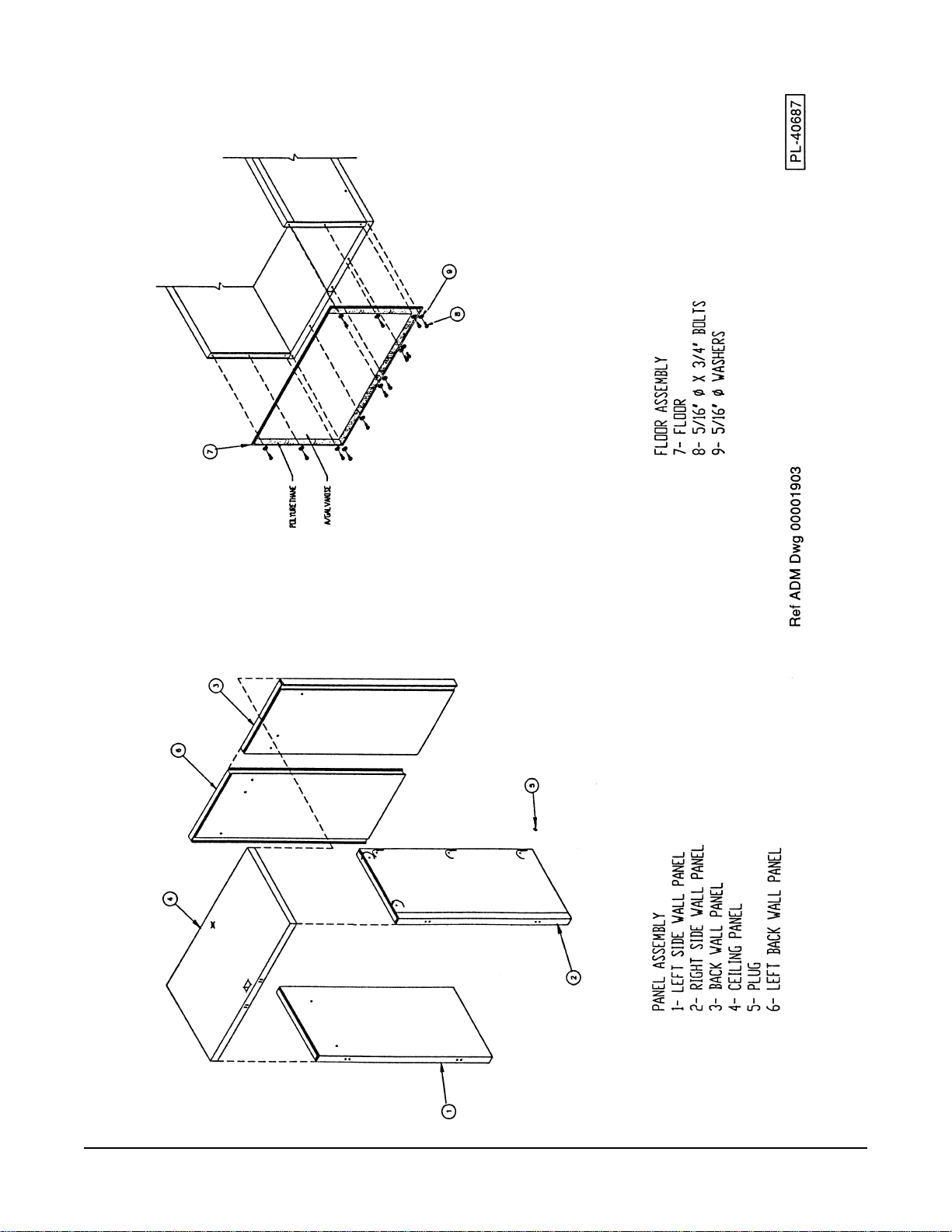
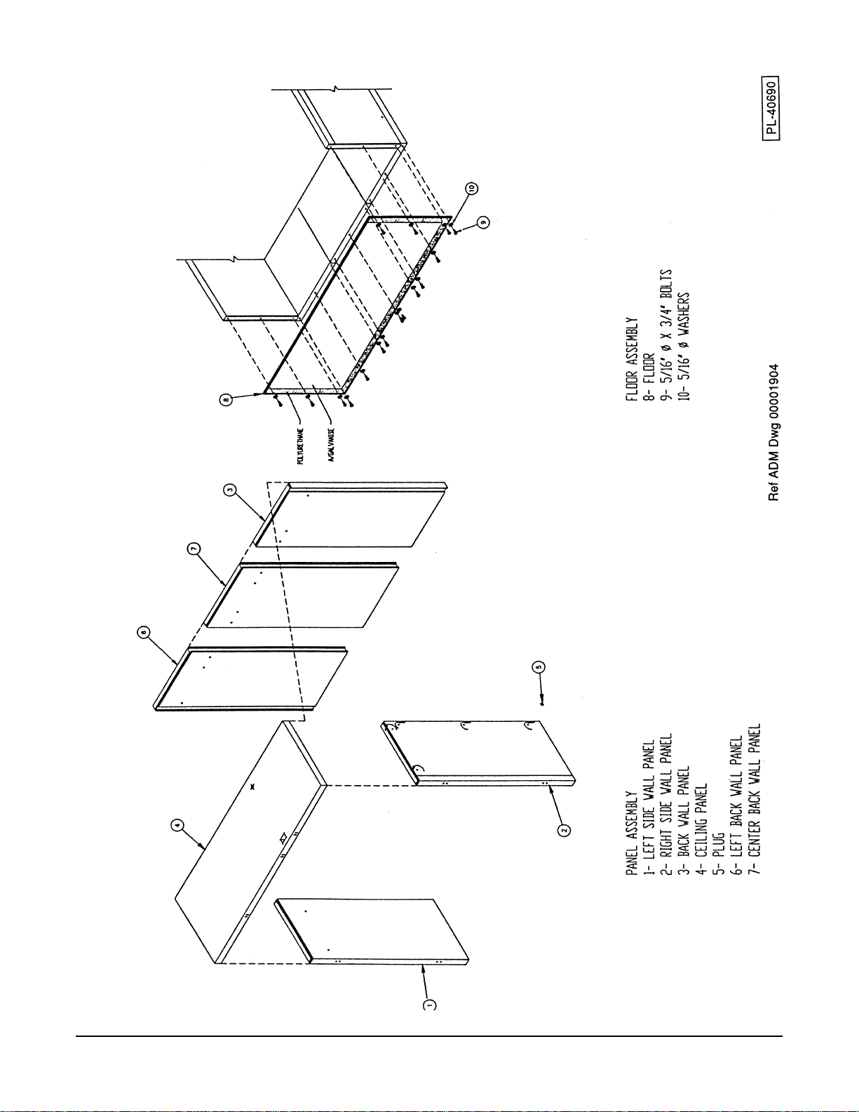
ASSEMBLY
Models AHP1S, AHPR1S, and AHTP1S are shipped completely assembled from the factory. Other
AHP Series Proofers are shipped knocked-down for installation on the job site. Ceiling and wall panels
are locked together with cam-locks; the floor is fastened to the wall panels with stainless steel screws.
Correctly install proofers following these step-by-step instructions:
1. If there are two or more back panels, place the back panels [B] in vertical, upright position. Insert
the hex wrench in the lock hole and turn clockwise until the locking arm strikes the pin in the adjacent
panel, locking panels together. If lock fails to engage, turn wrench counterclockwise and again turn
wrench clockwise until panels are properly locked together.
2. Tilt the assembled back panel(s) and lay them on the floor with the exterior side down.
3. Select the left side wall panel [S1]; place it in position with the back panel assembly; and, lock them
together with the cam lock by turning the hex wrench clockwise. Make sure top and bottom edges
of side and back panels are flush.
4. Repeat step 3 with the right side wall panel [S2].
5. Fasten the floor to the bottom of the back and side panels with stainless steel screws.
6. Place the roof panel [C] in position with the walls. First lock the roof panel [C] and the left side wall
panel [S1] by turning the hex wrench clockwise; then, lock the roof panel [C] and the right side wall
panel [S2] by turning the hex wrench counterclockwise.
7. The proofer box can now be put in an upright position.
8. For AHP and AHTP models: Lock the roof panel [C] to the back wall assembly by turning the hex
wrench clockwise.
9. For AHPR models:
a. Unlock the roof and side panel cam locks and install the mullion module (see pages 19 – 21).
b. Lock the roof and side panel cam locks.
c. Seal all joints between panels, ceiling, and floor with an NSF approved sealant, provided.
d. Assemble brass couplers, sight glass, and filter to the refrigeration lines on the evaporator and
condensing unit.
e. Install permagum around the refrigeration lines, add fiberglass insulation, and install sheet metal
covers on the ceiling (inside) and roof (outside) where refrigeration lines go through the ceiling.
f. Set the condensing unit on the top of the cabinet with the condensing coil facing front and the
refrigeration lines aligned. Fasten the condensing unit in place.
g. Connect the electric wires from the condensing unit to the controls: Pass wires through ceiling
to the opening for the controls and attach them to the terminal block. (220Volt: Wire 12 to
Wire 16 to
h. After completing steps 11 - 21, charge the refrigeration system with appropriate R22 or R134
refrigerant and install the condensing unit cover to the front at the top of the cabinet. For all
models: Low pressure Cut-Out = 13 psig; High pressure Cut-In = 22 psig.
10. For AHP and AHTP models: Seal all joints between panels, ceiling, and floor with an NSF approved
silicone sealant, provided. Slide the humidifying unit into place and fasten it to the ceiling and the
floor; the top and bottom cover plates of the control panels should be removed to allow access to
the mounting slots. It is recommended that the side cover of the humidifying unit be removed during
installation. On completion, seal humidifying unit at ceiling and floor using an NSF approved
silicone sealant, provided.
TB16, and Gnd to Gnd. 120Volt: Wire N to TBN, Wire 16 to TB16 and Gnd to Gnd).
TB12,
– 4 –
Page 5

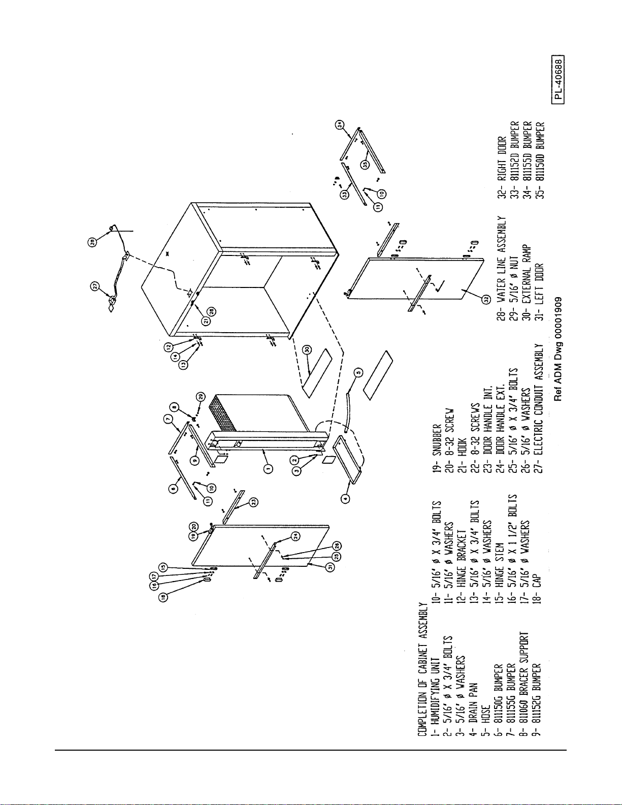
Steps 11 - 22 apply to all models:
11. Mount the bumper(s) at the upper part of the humidifying unit; fasten at front and back of control
panel by screwing bracket(s) to the wall with two stainless steel screws, each. Also mount the
bumpers on the back and side panels. Seal bumpers to walls and doors with an NSF approved
silicone sealant, provided.
12. Mount the hinge pin assembly to the front side wall(s). Place one nylon spacer behind each hinge
pin assembly.
13. Mount the white plastic halves with spacers on the door(s) but do not tighten screws.
14. Hang the door on the hinge pin assemblies: Carefully align the door with the door frame; press
against the door to make sure the seals are tight against the frame; and, tighten the white plastic
halves of the hinges making sure they are straight. If there are two or more doors, mount them in
the same way.
15. Mount the outside door handle/bumper and the inside bumper by screwing to the door and sealing
with an NSF approved silicone sealant, provided.
16. Mount the bracket for the door closer on the top of the door. Mount the hydraulic door closer (see
Fig. 47 on page 33.
17. Place the drain pan at the bottom of the humidifying unit. Fasten the plastic hose to the drain pan
with a hose clamp. Remove insulation from the knockout on either the left or right side wall panels;
pass the hose through the hole and continue to a floor drain. Refer to page 6.
18. Install the water supply line and solenoid assembly. A water filter (not supplied) is recommended
to remove particulates ahead of the spray nozzles in the humidifier. The water pressure should be
at least 43 psig (2 kg/cm
2
). Refer to page 6.
19. Install ramp(s).
20. Refer to page 6 for Electrical Connection information.
21. When the proofer has been set and leveled in its final installed position, seal all around the proofer
perimeter where it contacts the building floor with an NSF approved silicone sealant, provided.
Wipe off any excess sealant.
Refer to the drawings for your proofer:
Size (model number suffix) 2S — see pages 7 – 9.
Size (model number suffix) 3S — see pages 10 – 12.
Size (model number suffix) 1D — see pages 13 – 15.
Size (model number suffix) 2D — see pages 16 – 18.
Models AHPR — see pages 19 – 21.
– 5 –
Page 6

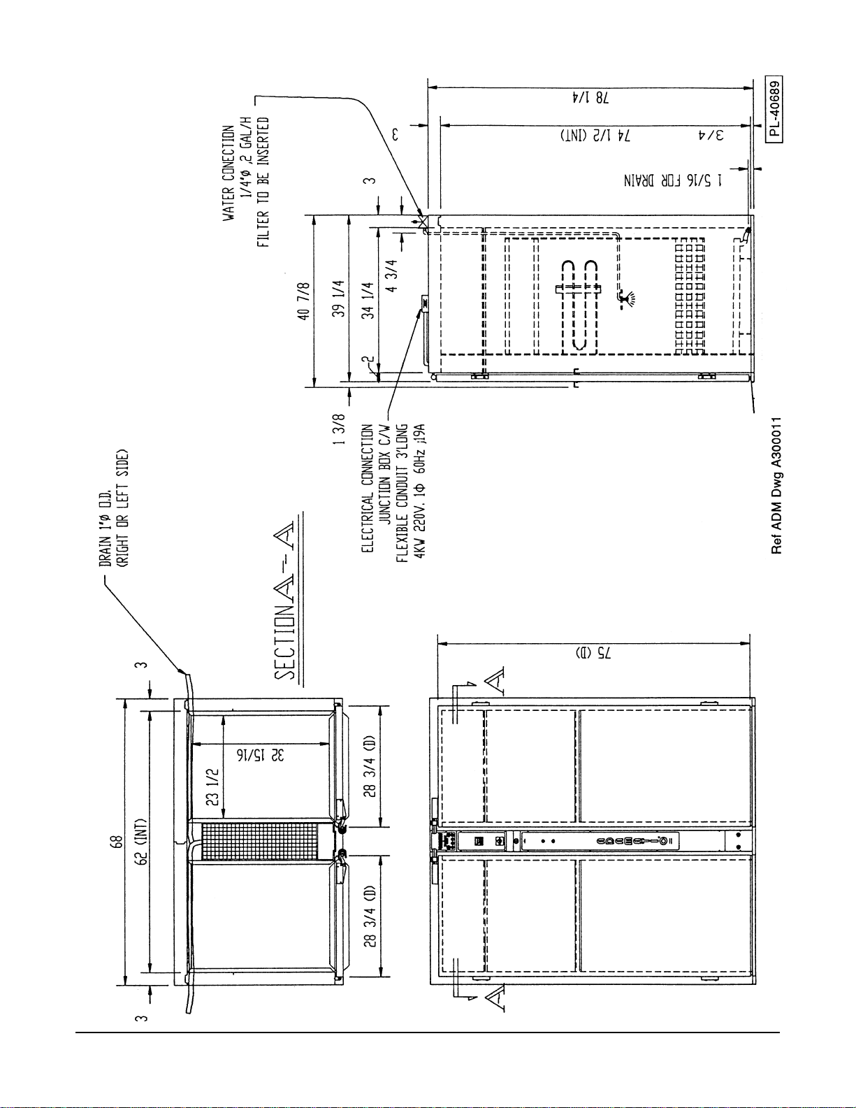
PLUMBING CONNECTIONS
WARNING: PLUMBING CONNECTIONS MUST COMPLY WITH APPLICABLE SANITARY, SAFETY,
AND PLUMBING CODES.
WATER SUPPLY
Water must be proper hardness and pH. The recommended hardness is 4 – 6 grains per gallon. The
recommended pH is 6.5 – 8.0. Consult your local water company and/or water conditioner dealer
before installing the AHP Series Roll-In Proof Box to make sure the water supply meets these
conditions.
Connect potable water supply to the
1
/4" NPT supply connection; the flow rate is 2 gallons per hour.
DRAIN CONNECTION
The drain hose connects to the 1" O.D. fitting at the bottom of the drain pan on the humidifying unit.
Overflow drain knockouts are provided on both ends of the cabinet to allow drain installation on either
end. Run the hose to a floor drain.
ELECTRICAL CONNECTION
WARNING: ELECTRICAL AND GROUNDING CONNECTIONS MUST COMPLY WITH THE
APPLICABLE PORTIONS OF THE NATIONAL ELECTRICAL CODE AND/OR OTHER LOCAL
ELECTRICAL CODES.
WARNING: DISCONNECT ELECTRICAL POWER SUPPLY AND PLACE A TAG AT THE DISCONNECT
SWITCH INDICATING THAT YOU ARE WORKING ON THE CIRCUIT.
ATADLACIRTCELE
esahP-ztreH-stloV
1-06-802/0211-06-802/021
1-06-802/0211-06-802/021
1-06-802/021
:srefoorP
S1PHA
S2PHA
S3PHA
D1PHA
D2PHA
:sredrateRrefoorP
S1RPHA
S2RPHA
S3RPHA
D1RPHA
D2RPHA
:srefoorPwahT
S1PTHA
S2PTHA
S3PTHA
D1PTHA
D2PTHA
0252AN
esahP-ztreH-stloV
1-06-042/0211-06-042/021
1-06-042/0211-06-042/021
1-06-042/021
02
02
03
02
03
02
03
02
03
03
03
04
03
04
esahP-ztreH-stloV
1-06-8021-06-802
1-06-8021-06-802
1-06-802
yticapmAtiucriCmuminiM
eciveDevitcetorPmumixaMeciveDevitcetorPmumixaM
eciveDevitcetorPmumixaMeciveDevitcetorPmumixaM
SPMASPMA
SPMASPMA
SPMA
eciveDevitcetorPmumixaM
52
52
04
52
04
AN
52
04
52
04
04
04
05
04
05
esahP-ztreH-stloV
1-06-0421-06-042
1-06-0421-06-042
1-06-042
51
51
02
51
02
AN
AN
02
AN
02
02
02
52
02
52
esahP/ztreH/stloV
1-06-0841-06-084
1-06-0841-06-084
1-06-084
– 6 –
.)noitidetsetal,07APFN(edoClacirtcelElanoitaNehthtiwecnadroccanidelipmoC
Page 7
MODELS AHP2S, AHPR2S, & AHTP2S
– 7 –
Page 8
MODELS AHP2S, AHPR2S, & AHTP2S
– 8 –
Page 9
MODELS AHP2S, AHPR2S, & AHTP2S
– 9 –
Page 10
MODELS AHP3S & AHPR3S
– 10 –
Page 11
MODELS AHP3S & AHPR3S
– 11 –
Page 12

MODELS AHP3S & AHPR3S
– 12 –
Page 13

MODELS AHP1D, AHPR1D, & AHTP1D
– 13 –
Page 14

MODELS AHP1D, AHPR1D, & AHTP1D
– 14 –
Page 15

MODELS AHP1D, AHPR1D, & AHTP1D
– 15 –
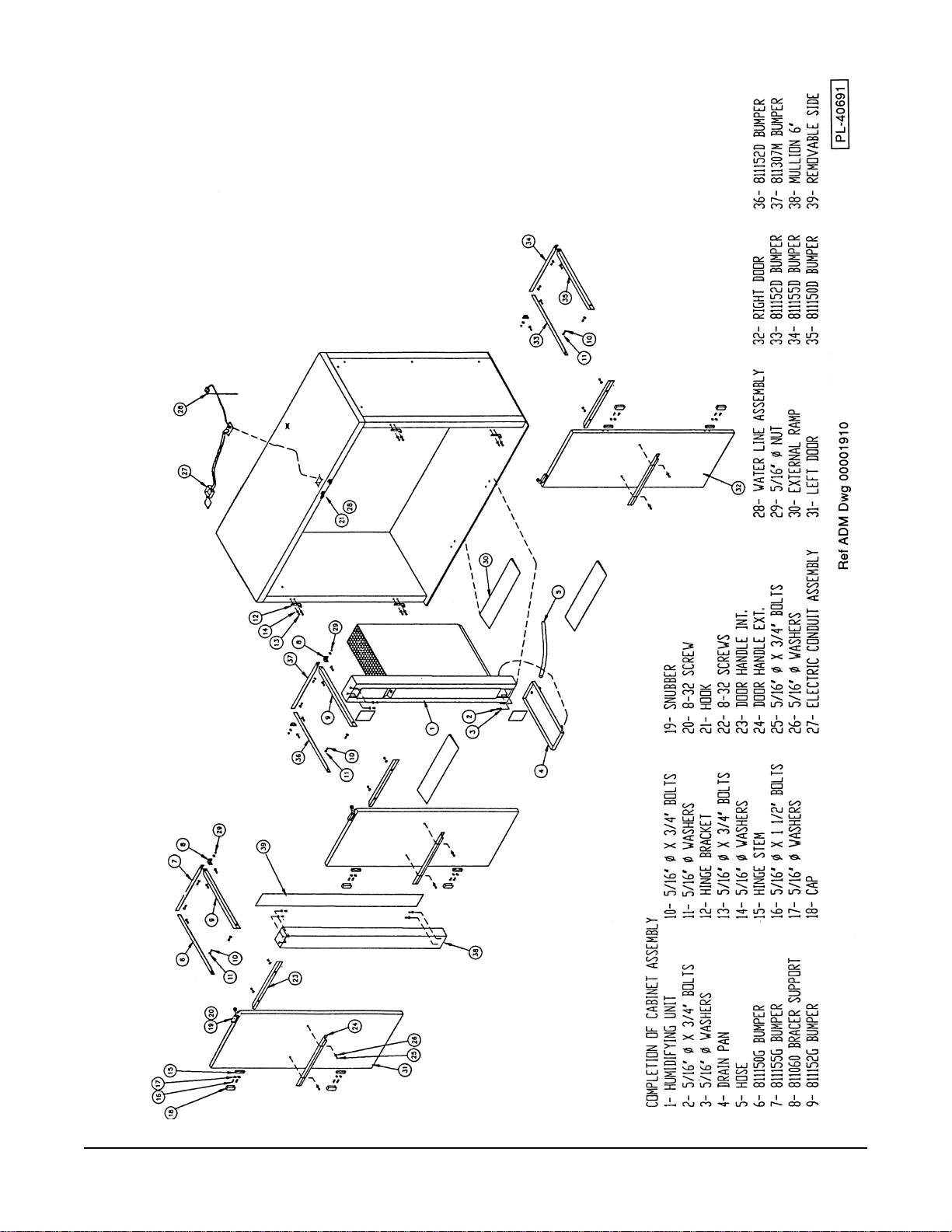
Page 16

MODELS AHP2D & AHPR2D
– 16 –
Page 17

MODELS AHP2D & AHPR2D
– 17 –
Page 18

MODELS AHP2D & AHPR2D
– 18 –
Page 19

MODEL AHPR2D SHOWN
– 19 –
Page 20

MODEL AHPR2D SHOWN
– 20 –
Page 21

MODELS AHPR2S, AHPR3S, AHPR1D, AHPR2D
– 21 –
Page 22

OPERATION
CONTROLS (Figs. 1, 2, & 3)
AHP models AHPR models AHTP models
Proofer Temperature
Main On-Off Switch
% Humidity
Pilot Light
Reset Button
On position uses the Proofer
Temperature Controller (E5CX)
and % Humidity.
7 Day Time Switch
Retarder Temperature
Proofer Temperature
Auto / Man Proof / Man Retard
Selector Switch
% Humidity
Main On-Off Switch
Pilot Light
Reset Button
Auto uses the 7 Day Time Switch discussed
on pages 23 – 32. Retard uses P2 and the
Retarder Temperature Controller (E5CX).
Proof uses P1, the Proofer Temperature
Controller (E5CX) and % Humidity.
Man Proof uses the Proofer Temperature
Controller (E5CX) and % Humidity.
Man Retard uses the Retarder Temperature
Controller (E5CX).
Thaw Temperature
Proofer Temperature
Auto / Off / Manual
Selector Switch
Proofer % Humidity
Thaw % Humidity
Pilot Light
Reset Button
Thaw Timer
Proofer Timer
Auto selects Timed Thawing followed by
Timed Proofing: Thawing uses Thaw
Timer and Thaw Temperature Controller
(E5CX); Proofing uses Proofer Timer,
Proofer Temperature Controller (E5CX),
and % Humidity.
Manual Proof uses the Proofer Temperature
Controller (E5CX) and % Humidity.
Fig. 1
Temperature Controller (E5CX) . . . For proofing, retarding, or thawing.
Actual Temperature
1234
Set Temperature
Use the Up and Down arrow keys
1234
OUT AT HB ALM
∨
∨
▲
∨
∨
Fig. 2
AT
to set the temperature.
Changed data becomes
effective 2 seconds after the
Up or Down key is released.
– 22 –
Page 23

7 Day Time Switch (H5S) — Models AHPR: Proofer-Retarder only (pages 23 – 32)
ON
Indicator Light
Write Key
Check Key
P1 - On Auto Off
Selector Switch
P2 - On Auto Off
Selector Switch
Time Adjust Key
Mode Selector
(Not Used)
SUN MON TUE WED THU FRI SAT
OUT
1 OUT 2
ON
AUTO
OFF
TIMER 1 2 MAN
MODE BOOT
■■
PULSE 1 2 AUTO
Cycle / Pulse Key
■
(Not Used)
SHIFT
DAY
SET/RESET
PROG
CHECK WRITE
TIME ADJ
CYCLE /PULSE COPY CLR
P1
P2
RUN
Copy Key
h
m
Day Shift Key
Day Set / Reset Key
Hour Set Key
Minutes Set Key
P1 P2 Run
Selector Switch
Clear Key
Fig. 3
NOTE: Times stored in P1 control Proofer functions; P2 time settings control the Retarder. The timer
prevents P1 (Proofer) and P2 (Retarder) set times from overlapping.
TO ERASE TIMES STORED IN P1 AND P2
RUN
P1
P2
P1
P2
RUN
P1
P2
RUN
Select P1 and press the CLR (Clear) key — this erases P1 memory.
Select P2 and press the CLR (Clear) key — this erases P2 memory.
NOTE: Use the RUN position during automatic operations to control the
Proofer-Retarder using the programmed start and stop times for each day
of the week.
TIMER MEMORY CAPACITY
The timer can be programmed for up to 24 events
in all. An event is a start date-time or a stop datetime. A start date-time and a stop date-time are the
two required events for every program. When 12
programs have been entered, the Event Number
(Fig. 4) will be reduced to 0 and no more programs
can be entered.
NOTE: The zero hour (0:00) on this timer is the
twelfth hour on most clocks. For example: 0:01 0:59 AM is 12:01 - 12:59 AM, just after midnight.
Also, 0:01 - 0:59 PM is 12:01 - 12:59 PM, afternoon.
SUN MON TUE WED THU FRI SAT
▼
— — — — — — —
— : — —
____________
_____↑
— : — — — : — —
Fig. 4
↓____24
Event
Number
1
PROG
– 23 –
Page 24

SETTING THE CURRENT DAY-OF-THE-WEEK AND TIME-OF-DAY
P1
P2
RUN
• Press the Time Adjust key for 2 to 3 seconds. The clock flashes (Fig. 6).
• Press the Day Shift key until the arrow,
• Press the Day Set / Reset key once to accept the Day-of-the-Week (Fig. 7).
Select the RUN position.
The display indicates the day
and time: Fig. 5 indicates it is
Tuesday, 8:15 am. If this is not
the correct Date and Time, reset
as follows:
SUN MON TUE WED THU FRI SAT
▼
— — — — — — —
▼
, is positioned on today's Day-of-the-Week.
SUN MON TUE WED THU FRI SAT
— — — — — — —
AM
_____↑
SUN MON TUE WED THU FRI SAT
— — — — — — —
8 : 1 5
___________ _
— : — — — : — —
Fig. 5
▼
↓____
AM
• Press the Hour Set key until the hour (and AM or PM) is displayed.
• Press the Minutes Set key until the minutes are displayed (Fig. 8).
• Press the Write key to validate (accept) the date and time (Fig. 9).
SUN MON TUE WED THU FRI SAT
— — — — — — —
PM
8 : 1 5
Fig. 6 Fig. 7
▼
2 : 2 1
AM
SUN MON TUE WED THU FRI SAT
— — — — — — —
PM
_____↑
8 : 1 5
▼
2 : 2 1
___________ _
↓____
— : — — — : — —
Fig. 8 Fig. 9
– 24 –
Page 25

PROGRAMMING START AND STOP TIMES FOR P1: PROOFER FUNCTIONS
P1
P2
RUN
Select the P1 position.
The display (Fig. 10) indicates that 24 events
SUN MON TUE WED THU FRI SAT
▼
— — — — — — —
or 12 programs can be entered (no programs
have been entered). The
P1-P2-RUN switch is
positioned on P1, indicated by
.
1
BLINKING
_____↑
— : — —
____________
The flashing date line and up arrow,↑,
indicate that the start date and time can be
— : — — — : — —
programmed. Once the start date and time
have been programmed, the flashing down
Fig. 10
arrow, ↓, prompts for the stop date and time.
▼
☞ Press the Day Shift key until the arrow,
, is positioned on the start day-of-week (Fig. 11).
• Press the Day Set / Reset key once to accept the start day-of-week (Fig. 12).
↓____24
1
PROG
SUN MON TUE WED THU FRI SAT
— — — — — — —
▼
— : — —
____________
BLINKING
_____↑
— : — — — : — —
Fig. 11 Fig. 12
↓____24
1
PROG
SUN MON TUE WED THU FRI SAT
— — — — — — —
▼
— : — —
____________
BLINKING
_____↑
— : — — — : — —
↓____24
1
PROG
• Press the Hour Set key until the start hour and AM or PM are displayed.
• Press the Minutes Set key until the start minutes are displayed (Fig. 13).
• Press the Write key to validate (accept) the start date and time (Fig. 14). The event number
changes from 24 to 23.
SUN MON TUE WED THU FRI SAT
— — — — — — —
▼
SUN MON TUE WED THU FRI SAT
— — — — — — —
▼
AM
8 : 2 0
____________
BLINKING
_____↑
— : — — — : — —
Fig. 13 Fig. 14
↓____24
1
PROG
_____↑
— : — —
____________
AM
8 : 2 0 — : — —
Programming the stop date and time for P1 continues on the next page.
– 25 –
BLINKING
↓___ _ 23
1
PROG
Page 26

NOTE: Skip the next two steps if the stop day-of-week is the same as the start day-of-week.
▼
• Press the Day Shift key until the arrow,
, is positioned on the stop day-of-week (Fig. 15).
• Press the Day Set / Reset key once to accept the stop day-of-week (Fig. 16).
SUN MON TUE WED THU FRI SAT
— — — — — — —
▼
— : — —
_____↑
AM
___________ _
8 : 2 0 — : — —
Fig. 15
BLINKING
↓____ 23
1
PROG
SUN MON TUE WED THU FRI SAT
— — — — — — —
▼
— : — —
_____↑
AM
___________ _
8 : 2 0 — : — —
Fig. 16
BLINKING
↓____ 23
1
• Press the Hour Set key, beginning at the start time (Fig. 17) and continue pressing
until the stop hour and AM or PM are displayed (Fig. 18).
SUN MON TUE WED THU FRI SAT
— — — — — — —
AM
_____↑
AM
▼
8 : 2 0
___________ _
8 : 2 0 — : — —
BLINKING
↓____ 23
PROG
1
SUN MON TUE WED THU FRI SAT
— — — — — — —
PM
_____↑
AM
▼
4 : – –
___________ _
↓____ 23
8 : 2 0 — : — —
BLINKING
1
PROG
PROG
Fig. 17 Fig. 18
• Press the Minutes Set key until the stop minutes are displayed (Fig. 19).
• Press the Write key to validate (accept) the stop date and time (Fig. 20). The display reverts
to Fig. 10 with the event number changed from 23 to 22.
SUN MON TUE WED THU FRI SAT
— — — — — — —
PM
_____↑
AM
▼
4 : 5 0
___________ _
8 : 2 0 — : — —
Fig. 19 Fig. 20
BLINKING
↓____ 23
PROG
1
The program is now complete. To enter another P1 program, repeat from ☞ on page 25; or, exit P1.
– 26 –
SUN MON TUE WED THU FRI SAT
— — — — — — —
▼
— : — —
____________
_____↑
AM
8 : 2 0 4 : 5 0
↓____ 22
PM
PROG
1
Page 27

PROGRAMMING START AND STOP TIMES FOR P2: RETARDER FUNCTIONS
SUN MON TUE WED THU FRI SAT
▼
— — — — — — —
RUN
P1
P2
Select the P2 position.
Fig. 21 indicates 18 events (9
programs) can yet be programmed.
P1-P2-RUN switch is set on P2.
The
The flashing date line and up arrow,↑,
_____↑
— : — —
____________
BLINKING
↓____18
indicate that the start date and time can be
programmed. Once the start date and time
— : — — — : — —
have been programmed, the flashing down
arrow, ↓, prompts you to program the stop
Fig. 21
date and time.
▼
☞ Press the Day Shift key until the arrow,
, is positioned on the start day-of-week (Fig. 22).
• Press the Day Set / Reset key once to accept the start day-of-week (Fig. 23).
SUN MON TUE WED THU FRI SAT
— — — — — — —
▼
— : — —
SUN MON TUE WED THU FRI SAT
— — — — — — —
▼
— : — —
2
PROG
BLINKING
_____↑
____________
↓____18
2
PROG
— : — — — : — —
Fig. 22 Fig. 23
_____↑
____________
BLINKING
— : — — — : — —
↓____18
2
PROG
• Press the Hour Set key until the start hour and AM or PM are displayed.
• Press the Minutes Set key until the start minutes are displayed (Fig. 24).
• Press the Write key to validate (accept) the date and time (Fig. 25). The event number
changes from 18 to 17.
SUN MON TUE WED THU FRI SAT
— — — — — — —
PM
▼
5 : 3 0
___________ _
BLINKING
_____↑
— : — — — : — —
↓ ____18
2
PROG
SUN MON TUE WED THU FRI SAT
— — — — — — —
▼
— : — —
_____↑
PM
____________
5 : 3 0 — : — —
BLINKING
↓____ 17
2
PROG
Fig. 24 Fig. 25
Programming the stop date and time for P2 continues on the next page.
– 27 –
Page 28

NOTE: Skip the next two steps if the stop day-of-the-week is the same as the start date.
▼
• Press the Day Shift key until the arrow,
, is positioned on the Day-of-the-Week (Fig. 26).
• Press the Day Set / Reset key once to accept the new Day-of-the-Week (Fig. 27).
SUN MON TUE WED THU FRI SAT
— — — — — — —
▼
— : — —
_____↑
PM
___________ _
5 : 3 0 — : — —
Fig. 26
BLINKING
↓____ 17
2
PROG
SUN MON TUE WED THU FRI SAT
— — — — — — —
▼
— : — —
_____↑
PM
___________ _
5 : 3 0 — : — —
Fig. 27
BLINKING
↓____ 17
2
• Press the Hour Set key, beginning at the start time (Fig. 28) and continue pressing
until the 'stop' hour and AM or PM are displayed (Fig. 29).
SUN MON TUE WED THU FRI SAT
— — — — — — —
PM
_____↑
PM
5 : 3 0
___________ _
5 : 3 0 — : — —
▼
BLINKING
↓____ 17
PROG
2
SUN MON TUE WED THU FRI SAT
— — — — — — —
AM
_____↑
7 : – –
___________ _
PM
5 : 3 0 — : — —
▼
BLINKING
↓____ 17
2
PROG
PROG
Fig. 28 Fig. 29
• Press the Minutes Set key until the stop minutes are displayed (Fig. 30).
• Press the Write key to validate (accept) the stop date and time (Fig. 31). The display reverts
to Fig. 10 with the event number changed from 17 to 16.
SUN MON TUE WED THU FRI SAT
— — — — — — —
AM
_____↑
7 : 3 0
___________ _
5 : 3 0 — : — —
PM
Fig. 30
▼
BLINKING
↓____ 17
PROG
2
The program is now complete. To enter another P2 program, repeat from ☞ on page 27; or, exit P2.
– 28 –
SUN MON TUE WED THU FRI SAT
— — — — — — —
▼
— : — —
___________ _
_____↑
PM
5 : 3 0 7 : 3 0
Fig. 31
↓____ 16
AM
PROG
2
Page 29

PROGRAMMING A PAUSE OR TIME DELAY BETWEEN TWO PROGRAMS
To program a pause between the stop time of one program and the start time of the next, set the stop
time prior to the next start time as shown in the following examples:
EXAMPLE MODE START DAY START TIME STOP DAY STOP TIME
1 P1: Proofer Monday 8:00 AM Monday 5:00 PM
2 P2: Retarder Monday 5:30 PM Tuesday 7:30 AM
3 P1: Proofer Tuesday 8:00 AM Tuesday 5:00 PM
Between the stop time for example 1 and the start time for example 2, a 30 minute delay has been
scheduled. Also, a 30 minute delay is scheduled between the stop time for example 2 and the start
time for example 3. During this time delay, the fans will continue to run for a maximum of 30 minutes.
PLANNING YOUR WEEKLY SCHEDULE
If several days of the week have the same schedule, they can all be in the same program. When
selecting the start days of the week, merely repeat the selection (use the Day Shift key followed by the
Day Set / Reset key repeatedly). Then select the start hour and minutes only once since they are to
be the same. Do the same for the stop days of the week and the stop hours and minutes. For example,
if the P1 Proofer function were to be the same as example 1 above for Monday, Tuesday, Wednesday,
Thursday, and Friday the final set displays would look like Figs. 32, 33.
SUN MON TUE WED THU FRI SAT
— — — — — — —
AM
8 : 0 0
▼
___________ _
_____↑
AM
8 : 0 0 – : – –
Fig. 32 Fig. 33
↓____ 23
PROG
1
SUN MON TUE WED THU FRI SAT
— — — — — — —
PM
5 : 0 0
▼
___________ _
_____↑
AM
8 : 0 0 5 : 0 0
↓____ 22
PM
PROG
1
If scheduling example 2 for five overnight retarder mode functions, the final set displays would look like
Figs. 34, 35. Notice the removal of Monday and inclusion of Saturday in the stop day selection.
SUN MON TUE WED THU FRI SAT
— — — — — — —
PM
5 : 3 0
▼
___________ _
_____↑
AM
5 : 3 0 – : – –
↓____ 21
PROG
2
SUN MON TUE WED THU FRI SAT
— — — — — — —
AM
7 : 3 0
▼
___________ _
_____↑
5 : 3 0 7 : 3 0
↓____ 20
AMPM
PROG
2
Fig. 34 Fig. 35
– 29 –
Page 30

PROGRAMMING AN OPERATION FOR LONGER THAN ONE DAY
The timer can be programmed to start one day and stop several days later. For example, to start at
8:30 AM Monday and stop at 11:30 AM Wednesday, the final set displays would look like Figs. 36 & 37.
Use the Day Set / Reset key to remove the Monday designation when setting the stop day. Then use
the Day Shift key twice and the Day Set / Reset key once to fix the stop day on Wednesday.
SUN MON TUE WED THU FRI SAT
SUN MON TUE WED THU FRI SAT
▼
— — — — — — —
AM
8 : 3 0
___________ _
_____↑
AM
8 : 3 0 – : – –
Fig. 36 Fig. 37
BLINKING
↓____ 23
— — — — — — —
AM
_____↑
PROG
1
AM
▼
1 1 : 3 0
____________
↓____ 22
8 : 3 0 1 1 : 3 0
AM
REVIEWING AND CHANGING THE SET TIMES FOR EITHER P1 OR P2
P1
P2
RUN
The set times for P1 can be reviewed and changed, if necessary, by setting the P1-P2-
UN switch on P1 and pressing the Write key. If necessary, change the settings using
R
the appropriate keys; then, press the Write key to continue. Each time the Write key is
pressed, the set times are displayed in the sequence they were set. Press the Write key
P1
P2
RUN
after all set times have been displayed.
Set the P1-P2-R
UN switch on P2 to review and change the settings for P2.
REVIEWING THE SET TIMES FOR BOTH P1 AND P2 FROM THE RUN POSITION
PROG
1
P1
P2
RUN
P1
P2
RUN
The set times for today can be reviewed with the P1-P2-R
UN switch on Run, by pressing
the Check key. First, the set times for P1 are displayed, starting from the earliest start
time. Then the set times for P2 are displayed. Press the Check key after all the set times
have been reviewed to return to the Run display. If the control is left untouched for 20
seconds, the Run display automatically returns.
To review the set times for a day-of-the-week other than today, press the Day Shift key
▼
until the arrow,
, is positioned on the desired day-of-week; then press the Day Set key.
Press the Check key to step through the
set times for this day in sequence. The
start times and stop times for P1 are
displayed beginning with the earliest start
SUN MON TUE WED THU FRI SAT
— — — — — — —
▼
times (Fig. 38). Then the start and stop
times for P2 are displayed. After all set
times have been displayed, the display
returns to the Run display. If the control
is left untouched for 20 seconds, the Run
display automatically returns.
– 30 –
___________ _
_____↑
AM
8 : 3 0 1 1 : 3 0
Fig. 38
AM
↓____ 22
1
PROG
Page 31

DAY OVERRIDE: Temporarily Copying Program(s) From One Day-Of-The-Week To Another
Both P1 and P2 program(s) can be copied from one day-of-the-week to another; the original settings
are restored after one week. This allows you to temporarily copy Sunday's program(s) to a holiday that
falls in the middle of the week and resume the normal schedule the next week. After copying, review
the settings as described on the previous page. The example copies Sunday's program(s) to
Wednesday.
UN switch positioned on Run, (display looks like Fig. 39), hold down the
RUN
With the P1-P2-R
P1
P2
Copy key for at least one second. Fig. 40 should display.*
Select the day you want to copy to (Wednesday); use Day Shift and Day Set / Reset keys
to select the day. Fig. 41 displays. Press the Write key. Fig. 42 displays.
Select the day you want to copy from (Sunday); use Day shift and Day Set / Reset keys
to select the day. Fig. 43 displays. Press the Write key. Fig. 44 displays.
*
NOTE: If Fig. 42 displays, a day override for the week has already been programmed; this can be cleared and reset.
SUN MON TUE WED THU FRI SAT
▼
— — — — — — —
AM
8 : 3 0
SUN MON TUE WED THU FRI SAT
▼
— — — — — — —
BLINKING
___________ _
_____↑
AM
9 : 0 0 5 : 0 0
Fig. 39 Fig. 40
SUN MON TUE WED THU FRI SAT
PM
↓____ 11
PROG
1
SUN MON TUE WED THU FRI SAT
PROG
— — — — — — —
SUN MON TUE WED THU FRI SAT
▼
— — — — — — —
▼
Fig. 41 Fig. 42
Fig. 43 Fig. 44
PROG
PROG
▼▼▼▼▼▼▼
BLINKING
— — — — — — —
SUN MON TUE WED THU FRI SAT
▼
— — — — — — —
AM
8 : 4 1
____________
_____↑
AM
9 : 0 0 5 : 0 0
↓____ 11
1
PM
PROG
PROG
– 31 –
Page 32

RUNNING A PROGRAM (Fig. 45)
SUN MON TUE WED THU FRI SAT
P1 (Proofing) is ON
P1 & P2 Switches on AUTO
▼
— — — — — — —
AM
_____↑
■■
AM
■
OUT
1
1 OUT 2
ON
AUTO
OFF
TIMER 1 2 MAN
MODE BOOT
PULSE 1 2 AUTO
Boot Switch on AUTO
9 : 3 0
____________
↓____ 11
9 : 0 0 5 : 0 0
PM
CHECK WRITE
Fig. 45
1
TIME ADJ
SHIFT
DAY
SET/RESET
h
m
PROG
RUN Position
P1
P2
RUN
The Current Time is 9:30 AM Monday.
P1 (Proofing) is operating. It started at 9:00
AM and will stop at 5:00 PM.
NOTE: When P2 (Retarding) is ON, 2 is displayed in the OUT and PROG boxes.
NOTE: When neither P1 nor P2 is running and P1 (Proofing) is the next program to be started,
1 is displayed in the PROG box and the programmed start and stop times are displayed. When
neither P1 nor P2 is running and P2 (Retarding) is the next program to be started, 2 is displayed
in the PROG box and the programmed start and stop times are displayed.
IN CASE OF POWER FAILURE
The Time Switch maintains memory during a power failure but there is no output, the display is off, and
the ON indicator light is not lit. With the BOOT switch on AUTO, the time switch resumes its operation
as programmed after power recovery. If the BOOT switch is on MANUAL, the keyhole indicator blinks
on the display screen after power recovery and the output does not turn on until the BOOT switch is
set on the AUTO position.
– 32 –
Page 33

HUMIDIFIER, HEATER, AIR FILTER, AND FAN UNIT (Fig. 46)
TEMPERATURE AND HUMIDITY PROBE
IS LOCATED IN RETURN AIR STREAM.
FANS CIRCULATE AIR DOWN
THROUGH HEATING ELEMENTS
AND THE AIR IS HEATED.
THE HEATED AIR STREAM
FLOWS THROUGH A FINE
MIST WATER SPRAY,
PICKING UP MOISTURE.
ANY LARGE WATER DROPS ARE
TRAPPED BY THE AIR FILTER.
HOT MOIST AIR IS DELIVERED TO
THE PROOFING CHAMBER.
CONTINUOUS RECIRCULATION
GENTLY REPEATS THE CYCLE.
EXCESS WATER
FLOWS TO DRAIN.
DOOR CLOSER (Fig. 47)
Fig. 46
Fig. 47
– 33 –
Page 34

RETARDING
The retarder temperature is usually set at 38°F. Defrosting frozen dough at retarder temperatures
takes 6 hours minimum; dough products can be stored for as long as 48 hours in the retarder using the
cool humid air so dough products do not dry out. Dough should not be refrozen after thawing. The
retarder slows the yeast fermentation process, reduces gas formation, and inhibits raising of dough.
Products removed from the retarder should be left at room temperature for 5 – 7 minutes before being
put in the proofer. This will reduce moisture condensation when cold metal pans are placed in the warm
humid proofer.
PROOFING
Controlled temperature and humidity in the proofer promotes yeast fermentation which generates gas
and causes the dough to rise. Proofing takes from 45 – 60 minutes depending on the product. A
temperature setting of 95°F and humidity at 85% are typical but will vary slightly depending on the
product being proofed. The chart below is for guidelines only — ask your dough supplier for technical
product reports to set up your own chart.
Proofing Baking
Product
Rolls 95°F 85% 55 min 375°F 12 sec 12 min
French Crust Bread
14 oz
French Crust Bread
10 oz
Bagels 85°F 85% 50 min 400°F 20 sec 15 min
Croissants 75°F 70% 30 min 360°F 0 12 min
Temperature
°F
90°F 90% 45 min 375°F 15 sec 20 min
90°F 85% 45 min 360°F 12 sec 18 min
% Humidity
Proof Time
Minutes
Temperature°FSteam Time
Seconds
Bake Time
Minutes
CLEANING
Clean the inside of the cabinet and the doors weekly with a warm water solution of mild household liquid
dishwashing detergent (such as Palmolive green or Ivory). Do not use anything containing grit,
abrasive materials, bleach, or harsh chemicals. Be cautious with new or improved formulas; use only
products approved for stainless steel. Rinse thoroughly and dry with a clean soft cloth. Do not use
steel wool to clean surfaces.
Remove the filter and rinse clean weekly. Replace filter when necessary.
NOTE: Failure to follow use, care and maintenance instructions may void your Hobart warranty.
– 34 –
Page 35

SERVICE
Contact your local Hobart-authorized service office for any repairs or adjustments needed on this
equipment.
– 35 –
Page 36

NOTES
FORM 19410 Rev.A (Aug. 2000) PRINTED IN U.S.A.
– 36 –
 Loading...