


查询HMC203供应商
5
MICROWAVE CORPORATION
Typical Applications
The HMC203 is ideal for:
• 18 GHz TVRO
• 23 GHz Telecom Radios
• Military Systems
Functional Diagram
v01.0801
HMC203
GaAs MMIC DOUBLE-BALANCED
MIXER, 14 - 23 GHz
Features
Conversion Loss: 10 dB
LO / RF Isolation: 38 dB
Passive: No DC Bias Required
Small Size: 0.87 mm x 1.48 mm
General Description
The HMC203 chip is a miniature double-balanced
mixer which can be used as an upconverter or
downconverter. Excellent isolations are provided
by on-chip baluns, which require no external components and no DC bias. The mixer chip can
be integrated directly into MMIC hybrid applications. Unless otherwise stated, all data was measured with the mixer mounted in a MMIC test
fi xture. The MMIC was connected to thinfi lm 50
ohm transmission lines with 1 mil diameter wirebonds of <10 mils in length.
MIXERS - CHIP
Electrical Specifi cations, T
Frequency Range, RF & LO 14 - 23 15 - 21 GHz
Frequency Range, IF DC - 2 DC -2 GHz
Conversion Loss 10 12 8.5 10 dB
Noise Figure (SSB) 10 12 8.5 10 dB
LO to RF Isolation 30 38 30 38 dB
LO to IF Isolation 35 45 35 45 dB
RF to IF Isolation 12 17 12 17 dB
IP3 (Input) 18 18 dBm
IP2 (Input) 40 40 dBm
1 dB Gain Compression (Input) 7 7 dBm
5 - 28
= +25° C, LO Drive = +15 dBm
A
Parameter Min. Typ. Max. Min. Typ. Max. Units
For price, delivery, and to place orders, please contact Hittite Microwave Corporation:
12 Elizabeth Drive, Chelmsford, MA 01824 Phone: 978-250-3343 Fax: 978-250-3373
Order Online at www.hittite.com
MICROWAVE CORPORATION
v01.0801
HMC203
GaAs MMIC DOUBLE-BALANCED
MIXER, 14 - 23 GHz
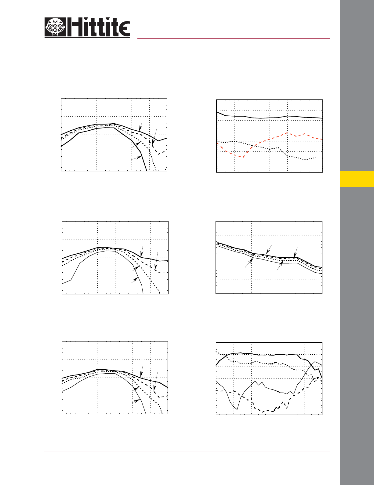
Conversion Loss vs LO Drive
0
-5
-10
-15
CONVERSION LOSS (dB)
-20
13 15 17 19 21 23 25
FREQUENCY (GHz)
+15 dBm
+12 dBm
+10 dBm
+8 dBm
Conversion Loss @ +85 C vs. LO Drive
0
-5
-10
-15
CONVERSION LOSS (dB)
-20
13 15 17 19 21 23 25
FREQUENCY (GHz)
+15 dBm
+12 dBm
+10 dBm
+8 dBm
Isolation, LO = +15 dBm
0
-10
-20
-30
-40
ISOLATION (dB)
-50
-60
-70
13 15 17 19 21 23 25
LO/RF
LO/IF
FREQUENCY (GHz)
RF/IF
IF Bandwidth LO = 18 GHz @ +15 dBm
0
-5
+15 dBm
-10
-15
CONVERSION LOSS (dB)
-20
-25
0246
+8 dBm
IF FREQUENCY (GHz)
+10 dBm
+12 dBm
5
MIXERS - CHIP
Conversion Loss @ -55 C vs LO Drive
0
-5
-10
-15
CONVERSION LOSS (dB)
-20
13 15 17 19 21 23 25
FREQUENCY (GHz)
For price, delivery, and to place orders, please contact Hittite Microwave Corporation:
12 Elizabeth Drive, Chelmsford, MA 01824 Phone: 978-250-3343 Fax: 978-250-3373
+15 dBm
+12 dBm
+10 dBm
+8 dBm
Order Online at www.hittite.com
RF Coplanar Probe Data LO = +12 dBm
0
-10
-20
-30
-40
-50
-60
CONVERSION LOSS AND ISOLATION (dB)
10 15 20 25 30 35 40
CONVERSION LOSS
RF/IF ISO
LO/RF ISO
LO/IF ISO
FREQUENCY (GHz)
5 - 29

5
MICROWAVE CORPORATION
v01.0801
Absolute Maximum Ratings
RF / IF Input +13 dBm
LO Drive +27 dBm
Storage Temperature -65 to +150 °C
Operating Temperature -55 to +85 °C
Outline Drawing
HMC203
GaAs MMIC DOUBLE-BALANCED
MIXER, 14 - 23 GHz
MIXERS - CHIP
5 - 30
NOTES:
1. ALL DIMENSIONS ARE IN INCHES [MM].
2. DIE THICKNESS IS .004”.
3. BOND PADS ARE .004” SQUARE.
4. BOND PAD SPACING CENTER TO CENTER IS .006”.
5. BACKSIDE METALLIZATION: GOLD.
6. BOND PAD METALLIZATION: GOLD.
7. BACKSIDE METAL IS GROUND.
8. CONNECTION NOT REQUIRED FOR UNLABELED BOND PADS.
For price, delivery, and to place orders, please contact Hittite Microwave Corporation:
12 Elizabeth Drive, Chelmsford, MA 01824 Phone: 978-250-3343 Fax: 978-250-3373
Order Online at www.hittite.com

MICROWAVE CORPORATION
v01.0801
HMC203
GaAs MMIC DOUBLE-BALANCED
MIXER, 14 - 23 GHz
Handling Precautions
Follow these precautions to avoid permanent damage.
Cleanliness: Handle the chips in a clean environment. DO NOT attempt to clean the chip using liquid cleaning systems.
Static Sensitivity: Follow ESD precautions to protect against > ± 250V ESD strikes.
Transients: Suppress instr ument and bias supply transients while bias is applied. Use shielded signal and bias cables to minimize
inductive pick-up.
General Handling: Handle the chip along the edges with a vacuum collet or with a sharp pair of bent tweezers. The surface of the
chip has fragile air bridges and should not be touched with vacuum collet, tweezers, or fi ngers.
Mounting
The chip is back-metallized and can be die mounted with AuSn eutectic preforms or with electrically conductive epoxy. The mounting
surface should be clean and fl at.
Eutectic Die Attach: A 80/20 gold tin preform is recommended with a work surface temperature of 255 °C and a tool temperature
of 265 °C. When hot 90/10 nitrogen/hydrogen gas is applied, tool tip temperature should be 290 °C. DO NOT expose the chip
to a temperature greater than 320 °C for more than 20 seconds. No more than 3 seconds of scr ubbing should be required for
attachment.
Epoxy Die Attach: Apply a minimum amount of epoxy to the mounting surface so that a thin epoxy fi llet is obser ved around the
perimeter of the chip once it is placed into position. Cure epoxy per the manufacturer’s schedule.
Wire Bonding
RF bonds made with 0.003” x 0.0005” ribbon are recommended. These bonds should be thermosonically bonded with a force of 4060 grams. DC bonds of 0.001” (0.025 mm) diameter, thermosonically bonded, are recommended. Ball bonds should be made with
a force of 40-50 grams and wedge bonds at 18-22 grams. All bonds should be made with a nominal stage temperature of 150 °C. A
minimum amount of ultrasonic energy should be applied to achieve reliab le bonds. All bonds should be as short as possible, less than
12 mils (0.31 mm).
5
For price, delivery, and to place orders, please contact Hittite Microwave Corporation:
12 Elizabeth Drive, Chelmsford, MA 01824 Phone: 978-250-3343 Fax: 978-250-3373
Order Online at www.hittite.com
MIXERS - CHIP
5 - 31
 Loading...