


MACHINING CENTER
VS40/50/60
INSTRUCTION MANUAL
APC
SEIKI - SEICOS å16M/18M
OB-2781-1-8001-E-1-01
18 Edition 1.01 02-2001
Hitachi Seiki Deutschland
Werkzeugmaschinen GmbH
2
CONTENTS
1. OUTLINE AND FEATURES ................................................................... |
1 -1 |
|
1-1 Configuration...................................................................................................................... |
1 -1 |
|
1-2 Name of Each Section ....................................................................................................... |
1 -2 |
|
2. SPECIFICATION .................................................................................... |
2 -1 |
|
2-1 Table of the Specifications ................................................................................................. |
2 -1 |
|
2-2 Main Dimension Diagram ................................................................................................... |
2 -2 |
|
2-3 Pallet Dimension Diagram ................................................................................................. |
2 -5 |
|
2-4 Workpiece Interference Range ........................................................................................ |
2 -11 |
|
3. OPERATION 3 -1 |
|
|
3-1 |
Operation Procedure ......................................................................................................... |
3 -1 |
3-2 Individual Movement (At MDI or Maintenance Mode) ....................................................... |
3 -4 |
|
3-3 Treatment at Power Failure or Emergency Stop ................................................................ |
3 -5 |
|
3-4 APC Program ..................................................................................................................... |
3 -8 |
|
4. TRANSPORTATION AND INSTALLATION OF THE MACHINE ........... |
4 -1 |
|
4-1 Transportation of the Machine ........................................................................................... |
4 -1 |
|
4-2 Environment for Machine Installation ................................................................................. |
4 -5 |
|
4-3 Construction of Foundation ................................................................................................ |
4 -6 |
|
4-4 Installation of Machine ..................................................................................................... |
4 -10 |
|
5. INSPECTION AND ADJUSTMENT ....................................................... |
5 -1 |
|
5-1 |
Daily Inspection ................................................................................................................. |
5 -1 |
5-2 |
Diagnosis No. .................................................................................................................... |
5 -2 |
5-3 |
Hydraulic · Pneumatic Circuit Diagram ............................................................................. |
5 -3 |
5-4 Expendable Parts List ........................................................................................................ |
5 -5 |
|
i
ii

1. OUTLINE AND FEATURES
This APC (automatic pallet changer) unit is based on “hydraulic unit less” system realized by VS series standard model, and is featured by its ECO, ECO (ecology and economy) specifications with high speed and high reliability. It enables men to relieve from periodic maintenance of hydraulic oil required by the conventional system and to reduce the running cost.
1-1 Configuration
1-1-1 Saddle (Pallet Table)
For the pallet clamp/unclamp action, high pressure (about 40kgf/cm2) hydraulic power converted from compressed air amplified by air hydro-unit is used. Use of air pressure for the purpose requiring high power such as pallet clamp unit has hitherto been generally considered unsuitable, however, this problem has been solved by converting air pressure energy into hydraulic pressure.
1-1-2 APC Main Unit
For the APC main unit, rotary arm type exchange system is adopted. The relative movement of a rotary arm driven by an inverter motor and two lines of groves on the pallet runs the system. Compared with the conventional hydraulic system, this system enables smoother and quicker pallet change and, furthermore, higher reliability is achieved with simple construction by reducing the number of parts nearly to a half.
1-1-3 Splash Cover
The processing area is covered with splashguard up to the ceiling as a fully enclosed space. The processing area is separated from the APC rearranging area by an automatic shutter driven by an electric motor for protection against the splash of coolant and chips.
1 - 1

1-2-1 |
2-1 |
Machine Whole |
Each of Name |
|
Section |
|
11 |
Automatic door |
|
|
|
|
|
|
10 |
Left pallet |
|
1 |
|
|
|
9 |
Pallet guide |
||
2 - |
|||
|
|
||
8 |
Right pallet |
||
|
|||
|
|
|
|
|
7 |
APC individual |
|
|
operation panel |
||
|
|
||
|
|
|
|
|
6 |
Guard |
|
|
|
|
|
|
5 |
Chip box |
|
|
|
|
|
|
4 |
Coolant tank |
|
|
|
|
|
|
3 |
Base |
|
|
|
|
|
|
2 |
Saddle |
|
|
|
|
|
|
1 |
Air hydro-unit |
|
|
|
|
|
|
No. |
Name |
|
|
|
|
APC : Option

3 - 1
Name of Each Part of APC Unit
Rotary arm
Guide rail
Temporary fixing plunger
Pallet (T-groove specification)
Middle point positioning pin
*The photograph is taken with the left pallet removed for convenience of explanation of explanation.
2-2-1

4 - 1
3-2-1
Name of Each Part of Air Hydro-unit
Regulator |
Check valve |
Solenoid valve
Reservoir tank
Clamp booster
Flow rate valve
Unclamp booster
Rapid air release valve
*Photograph shows the air hydro-unit at the back of the machine proper. The cover is detached for convenience of explanation.
2. SPECIFICATION
2-1 Table of the Specifications
|
|
VS40 |
VS50 |
VS60 |
|||
|
|
|
|
|
|
|
|
Pallet size |
mm |
800 × |
400 |
1000 × |
450 |
1200 × |
560 |
|
|
|
|
|
|
|
|
Contour of pallet top (Type 1) |
|
M16 × |
P80 |
M16 × |
P80 |
M16 × |
P100 |
|
|
|
|
|
|||
(Type 2) |
|
18mm T-grove × 3 |
18mm T-grove × 4 |
18mm T-grove × 5 |
|||
|
|
|
|
|
|
|
|
No. of pallet |
|
2 |
|
2 |
|
2 |
|
|
|
|
|
|
|
|
|
Max. loading capacity of |
kg |
250 |
400 |
750 |
|||
|
|||||||
pallet |
|
|
|
|
|
|
|
|
|
|
|
|
|||
Pallet clamping power |
kg |
1850 |
3700 |
3700 |
|||
|
|
|
|
|
|||
Distance from spindle end to |
mm |
80 ~ 530 |
100 ~ 550 (Type 1) |
130 ~ 580 |
|||
|
|
|
|
|
|||
pallet top surface |
mm |
60 ~ 510 |
80 ~ 530 (Type 2) |
130 ~ 580 |
|||
|
|
|
|
|
|||
Changing system |
|
Rotary arm type |
Rotary arm type |
Rotary arm type |
|||
|
|
|
|
|
|
|
|
|
|
parallel shuttle |
parallel shuttle |
parallel shuttle |
|||
|
|
|
|
|
|||
Distance from floor level to |
mm |
950 (Type 1) |
1000 (Type 1) |
1020 (Type 1) |
|||
|
|
|
|
|
|||
pallet top surface |
mm |
970 (Type 2) |
1020 (Type 2) |
1020 (Type 2) |
|||
|
|
|
|
|
|||
Machine weight (gross) |
kg |
8300 |
9200 |
12300 |
|||
|
|
|
|
|
|
|
|
2 - 1
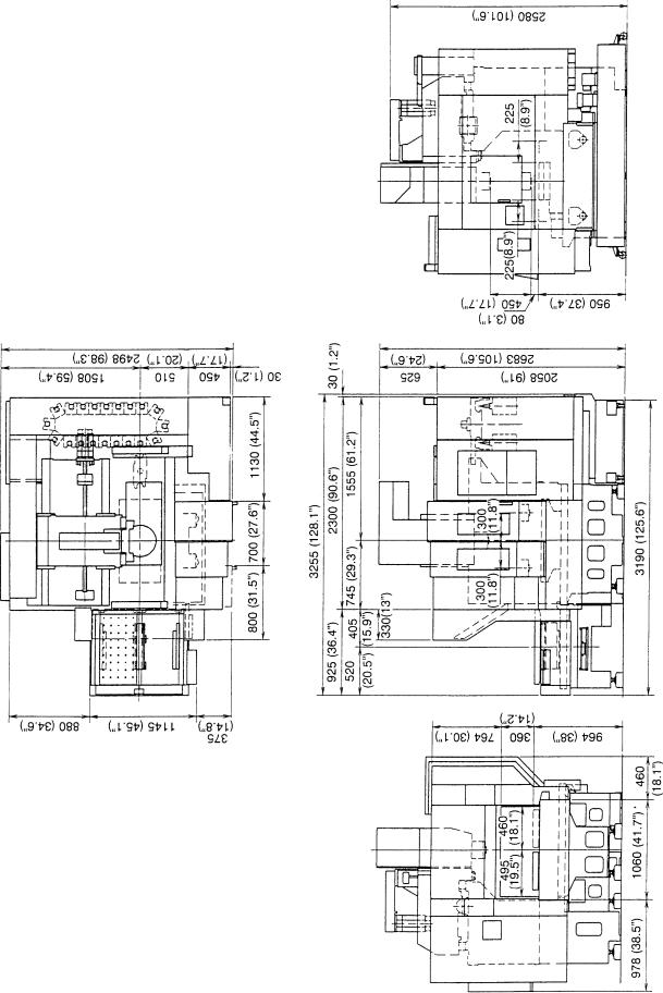
2-2 Main Dimension Diagram
2 - 2
VS50
2 - 3

2 - 4
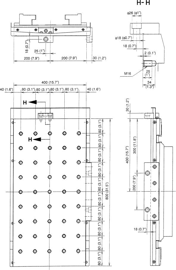
2-3 Pallet Dimension Diagram
VS40 Pallet Tapping Hole Specification
Dimension : metric (mm) Inch ( ” )
2 - 5
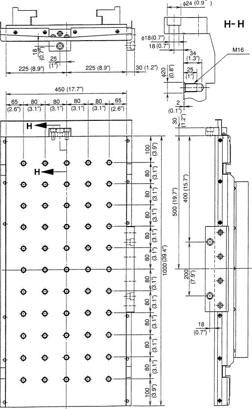
VS50 Pallet Tapping Hole Specification
Dimension : metric (mm)
Inch ( ” )
2 - 6
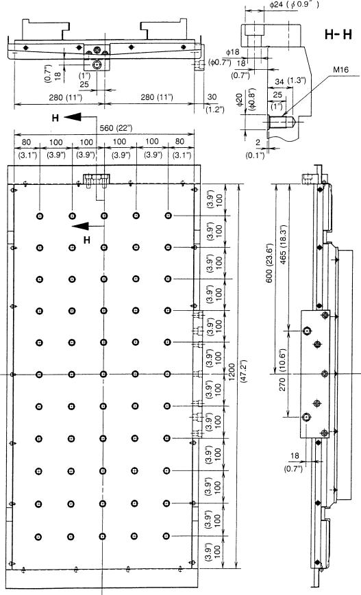
VS60 Pallet Tapping Hole Specification
Dimension : metric (mm)
Inch ( ” )
2 - 7
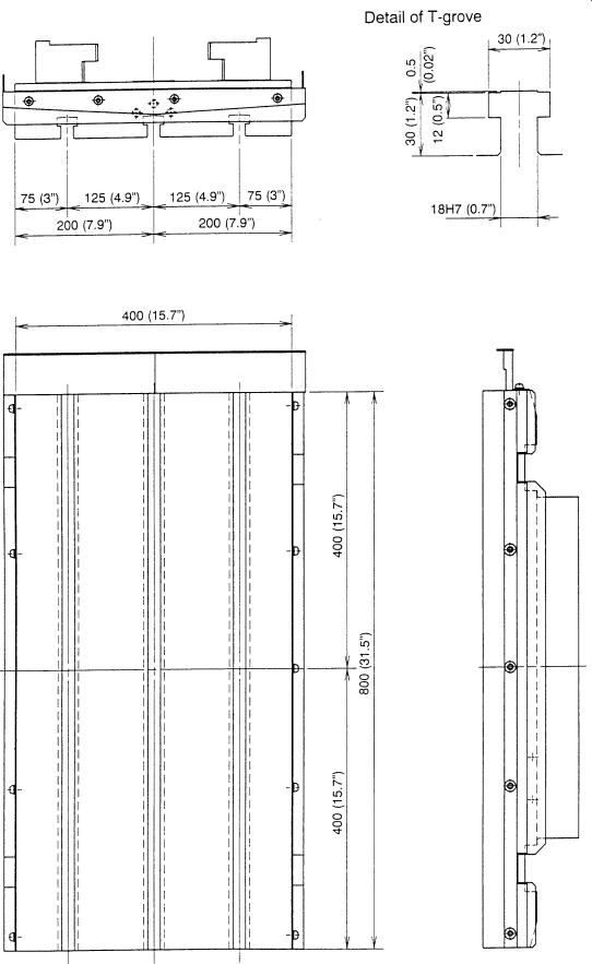
VS40 Pallet T-groove Specification
Dimension : metric (mm)
Inch ( ” )
2 - 8
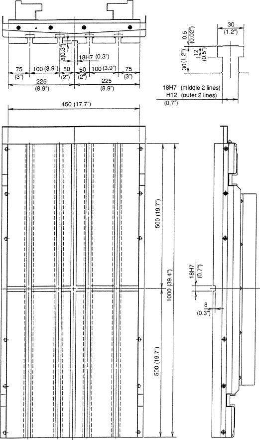
VS50 Pallet T-groove Specification
Detail of T-grove
Dimension : metric (mm) Inch ( ” )
2 - 9
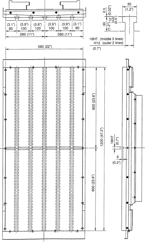
VS60 Pallet T-groove Specification
Detail of T-grove
Dimension : metric (mm) Inch ( ” )
2 - 10
 Loading...