


INVERTED VERTICAL TURNING CELL
CS20/25
INSTRUCTION MANUAL
57 SPECIFICATION
SEIKI - SEICOS å21L
Edition 2.02
Hitachi Seiki Deutschland
Werkzeugmaschinen GmbH
Introduction
Thank you for your having purchased the machine, favoring our product lines for your use.
This manual contains fundamental information on the specification. Please read and fully understand the contents for your safe machine operation.
In particular, the contents of the items concerning safety in this manual and the descriptions on the “caution plates” attached to the machine are important. Please follow the instructions contained and keep them always in mind to ensure safe operation.
The reference record papers on adjusting setting values such as a parameter list are attached to the machine unit and enclosed in the packing. These are necessary for maintenance and adjustment of the machine later on. Please keep them safely not to be mislaid.
The design and specifications of this machine may be changed to meet any future improvement. As the result, there may arise some cases where explanations in this manual could become partly inconsistent with the actual machine. Please note this point in advance.
In this manual, items on the standard and optional specifications are handled indiscriminately. Please refer to the “delivery note” for the detailed specification of your machine confirmation.
CONTENTS
1. General Precautions ........................................................................... |
1 - 1 |
|
1-1 Precautions on Machine Operation ................................................................................... |
1 - 1 |
|
1-2 Electric Equipment and NC Unit ........................................................................................ |
1 - 4 |
|
1-3 Weights and Measures Table ............................................................................................ |
1 - 5 |
|
2. SPECIFICATIONS ............................................................................... |
2 - 1 |
|
2-1 Machine Outline ................................................................................................................ |
2 - 1 |
|
2-2 Component Units .............................................................................................................. |
2 - 2 |
|
2-3 Machine Specifications ..................................................................................................... |
2 - 3 |
|
2-4 NC Unit Specifications ....................................................................................................... |
2 - 6 |
|
2-5 Major Dimensions ........................................................................................................... |
2 - 10 |
|
3. REQUIRED DIMENSION FOR MACHINE ........................................... |
3 - 1 |
|
3-1 Spindle Traveling Range ................................................................................................... |
3 - 1 |
|
3-1-1 12-station Base Holder Turret Head Type ................................................................. |
3 - 1 |
|
3-1-2 12-station VDI/VDI Rotating Tool Turret Head Type .................................................. |
3 - 6 |
|
3-2 Output Diagram .............................................................................................................. |
3 - 13 |
|
3-3 Chucking Pressure-Gripping Force Diagram .................................................................. |
3 - 16 |
|
3-4 Method of Obtaining Tool Center Height ......................................................................... |
3 - 18 |
|
4. Tooling System ................................................................................... |
4 - 1 |
|
4-1 |
CS20 12-station Base Holder Turret Head Assembly Tools (Standard) ........................... |
4 - 1 |
4-2 |
CS20 12-station Base Holder Turret Head Assembly Tools (Selected) ........................... |
4 - 2 |
4-3 |
CS25 12-station Base Holder Turret Head Assembly Tools (Standard) ........................... |
4 - 4 |
4-4 |
CS25 12-station Base Holder Turret Head Assembly Tools (Selected) ........................... |
4 - 5 |
4-5 |
CS20 12-station VDI Turret Head Assembly Tools (Standard) ......................................... |
4 - 7 |
4-6 |
CS25 12-station VDI Turret Head Assembly Tools (Standard) ......................................... |
4 - 8 |
4-7 |
CS20/25 12-station VDI Turret Head Assembly Tools (Selected) .................................... |
4 - 9 |
4-8 |
CS20 12-station VDI Rotating Tool Turret Head Assembly Tools (Standard) ................. |
4 - 11 |
4-9 |
CS25 12-station VDI Rotating Tool Turret Head Assembly Tools (Standard) ................. |
4 - 12 |
4-10 |
CS20/25 12-station VDI Rotating Tool Turret Head Assembly Tools (Selected) .......... |
4 - 13 |
i

1. General Precautions
General descriptions is very useful for making working environment against accidents and increase productivity.
1.Be sure to put safety goggles on.
2.Be sure to put safety shoes on.
3.Operate with proper dressing, such as putting a utility cap on, fixing the sleeves and the cuffs of working clothes.
4.Don’t operate the machine with gloves.
5.Make clean and neat environment by lighting up and keeping dry around the machine. Also don’t put any obstacles.
6.Remove dust and chips on the machine, high voltage control panel and NC unit. Also remove them on the floor. Avoid using compressed air as much as possible for these cleanings.
7.Use a strong enough table to be put around the machine, and take anti-sliding measures on the surface.
8.Don’t put tools, workpieces, and other items on the machine as well as on the moving parts of the machine.
9.Don’t give any remodeling to the machine without our permission.
1-1 Precautions on Machine Operation
When conducting trial run, read the manual applied to the machine carefully for full understanding beforehand. Witness of our operation instructor is most preferable.
Maintenance
1.An operator and maintenance personnel should read the precautions on the caution plate fitted to the machine and observe them.
Don’t stain, damage or remove the caution plate becomes hard to read, contact Hitachi Seiki.
2.Close all the doors and covers except when adjusting work is made.
As for the doors of the NC unit and the power control cabinet, be sure to close them with special care.
3.Don’t remove or modify the limit switches for the stroke end, for the travelling axes and the mechanism, or the electric circuit employed for safety.
4.Use regular wrenches and spanners for adjusting or repairing work.
5.When repairing the machine, be sure to perform lock-out or tag-out so that power switch may not be operated.
1 - 1

Coolant
This machine doesn’t mix coolant with lubrication oil by using the economy pack. But, the soluble cutting fluid is decomposed due to the factors such as propagation of microorganisms, which causes various troubles by lowering cutting and rust prevention performance.
When using soluble cutting fluid, care must be taken of the following points.
1.When selecting soluble cutting fluid, carefully consider lubrication, infiltration, rust prevention, bubble prevention, separability against oil and safety needs.
2.Before operation starts and after operation ends, not only remove chips, but also wipe off soluble cutting oil adhered to each slideway, the rotating parts, the saddle and cross-slide of the machine and then be sure to apply lubrication oil thinly to those parts.
3.Replace soluble cutting fluid immediately if it becomes vitiated.
4.Remove the covers every 6 months and clean each slideway, X, Y, Z axes ball-screws, each limit switch and feed motors etc.
5.As soluble cutting oil is considered for rust prevention, it may be no problem when the workpiece is wet. However, when dry, it is apt to rust.
Therefore, it is recommendable to apply rust preventive oil before the workpiece dries after finished machining.
6.Since soluble oil is alkalescent and has a strong decreasing action, the operator is apt to develop dermatitis.
Therefore, the operator should take appropriate precautions.
7.As for the diluting method and soluble cutting fluid, diluting water they are different depending on the type of soluble cutting oil, so use it in accordance with the recommendations of the cutting fluid manufacturer.
8.Since there are instances where extensive micro-organisms are detected in industrial water, it is recommendable either to check it before use as water for dilution or to use service water.
9.Do not use a chemical solution type (synthetic type) in water-soluble cutting agents, because it causes detachment of coating anf affects sealing materials and resin materials adversely.
10.The influences of difference kinds of oil on coolant are as follows: Carefully monitor the condition the coolant fluid.
|
|
|
|
|
|
|
Mixture |
|
|
|
|
Instabilization |
|
|
Density |
|
|
|
|
|
|
|
||
Different kinds of oil |
|
|
(Emulsification) |
|
|
|
|
of liquid |
|
|
abnormality |
|
|
|
|
|
|
|
||||||
|
|
|
|
|
|
|
|
|
|
|
|
|
|
|
|
|
|
|
|
|||||
|
|
|
|
|
|
|
|
|
|
|
|
|
|
|
|
|
|
|
||||||
|
|
|
|
|
|
|
|
|
|
|
|
|
|
|
|
|
|
|
||||||
|
|
|
|
|
|
|
|
|
|
|
|
|
|
|
|
|
|
|
|
|
|
|
|
|
|
|
|
|
|
|
|
|
|
|
|
|
|
Adhesion to |
|
|
|
Propagation of |
|
|
|
|
|
||
|
|
|
|
|
|
|
|
|
|
|
|
|
machine |
|
|
|
bacilli |
|
|
|
|
|
||
|
|
|
|
|
|
|
|
|
|
|
|
|
|
|
|
|
|
|
|
|
||||
Lubrication oil |
|
|
|
|
|
|
|
|
|
|
|
|
|
|
|
|
|
|
|
|
|
|
|
Petrifaction, |
|
|
|
|
|
|
|
|
|
|
|
|
|
|
|
|
|
|
|
|
|
|
|
||
|
|
|
|
|
|
|
|
|
|
|
|
|
|
|
|
|
|
|
|
|
|
|
|
|
|
|
|
|
|
|
|
|
|
|
|
|
|
|
|
|
|
|
|
|
|
|
|
|
rust & others |
|
|
|
|
|
|
|
|
|
|
|
|
|
|
|
|
|
|
|
|
|
|
|
|
|
|
|
|
|
|
|
|
Nutritive source of |
|
|
Propagation of |
|
Lowering of density |
|
|
|
|||||||||
|
|
|
|
|
|
|
micro-organism |
|
|
bacilli |
|
Lowering of pH |
|
|
|
|||||||||
Rust preventive oil |
|
|
|
|
|
|
|
|
|
|
|
|
|
|
|
|
|
|
|
|
|
|
|
|
|
|
|
|
|
|
|
|
|
|
|
|
|
|
|
|
|
|
|
|
|
|
|
||
|
|
|
|
|
|
|
|
|
|
|
|
|
|
|
|
|
|
|
|
|
|
|
|
|
|
|
|
|
|
|
|
|
|
|
|
|
|
|
|
|
|
|
|
|
|
|
|
|
|
|
|
|
|
|
|
|
Seal due to |
|
|
|
|
|
|
|
|
|
Formation of state |
|
|
|
||||
|
|
|
|
|
|
|
surfacing |
|
|
|
|
|
|
|
|
of aversion |
|
|
|
|||||
|
|
|
|
|
|
|
|
|
|
|
|
|
|
|
|
|
|
|
|
|||||
|
|
|
|
|
|
|
|
|
|
|
|
|
|
|
|
|
|
|
|
|
|
|
|
|
1 - 2

Operation
1.Be aware of the position of the push button for emergency stop so that the operator may be able to press it instantly.
2.As for the operation of the machine, proceed in accordance with the procedure described later.
3.During operation, keep hands away from the rotating sections and movable sect ions.
4.When disposing of chips that wound round tooling or fell onto the chip brow, etc. it is dangerous to grasp and pull them. Further, when disposing of chips, be sure to do it after stopping the machine.
5.When adjusting the position of the coolant nozzle, do it after stopping the machine.
Tool Setting
1.When setting up tools, stop a spindle as well as the feed in each axis.
2.Be very careful of tool length when setting them up. Do not set the tools over their specified lengths because their tool edges may interfere with a bed, carriage, cover, tailstock, etc. when indexing a turret.
3.Mount tools in a well balance condition. Due to high-speed turret indexing when their mounting is unbalanced, it may lead to improper turret indexing.
4.When setting a tool to the rotating tool, it is feared that the driving side may be damaged, if it is performed in the machine.
Whenever tools are set, be sure to do it at the outside of machine.
Workpiece Chucking
1.When chucking a workpiece, be careful of its balance. Do not turn the spindle if the mounting of the workpiece is unbalanced badly.
2.Use standard soft jaws. Mount the jaws so that they may stay within the outer diameter of the chuck.
3.To set pressure of chuck cylinder, determine it referring to “Chucking Pressure-Gripping Force Diagram”.
Take note that the chuck gripping force will be suddenly reduced due to a centrifugal force when the spindle runs at a high speed.
4.When forming the soft jaws, pay full attention to a forming ring gripping position and a shape to which the jaws are to be formed.
After forming, check that the jaws properly grip the workpiece and that a chucking pressure is adequate.
5.When chucking and centering a shaft work, take special note of a workpiece weight, a size of center hole and a thrust force.
If a heavy workpiece is held with a small center hole and a load is applied, the tip of the center may be damaged, allowing the workpiece to jump out.
1 - 3

Operation Finish
1.After operation of the machine is over, be sure to switch the power OFF in the prescribed order, clean the machine and apply rust preventive oil to each section of the machine such as the slide ways.
When soluble cutting fluid is used, perform these jobs with special care.
1-2 Electric Equipment and NC Unit
When operating the machine or carrying out maintenance checks, pay special attention to the following points, concerning the electric equipment and NC unit.
1.Do not give shocks to the NC unit, power control cabinet and other machine parts.
2.For the primary wiring of the machine, use the cable size specified in the maintenance manual. Do not use an excessively long cabtire cable.
When the primary wiring has to be put on the floor, protect it with a cover against damage by cutting chips and other sharp objects.
3.While test running the machine, be sure the setting parameter of the NC unit coincides with the parameter sheet attached to the machine.
4.Do not change the current set values of thermal relays in the power control cabinet, various control knobs or the parameter data.
5.Do not apply excessive force, e.g. bending force etc., to the connector portion of plugs, flexible conduits (tubes) or cabtire cables etc.
6.When carrying out maintenance checks on the electric equipment, turn off the EMERGENCY STOP button on the operation panel, the power of the NC unit, the main switch of the power control cabinet and the power switch installed in your factory, in this order.
Start maintenance work after making sure that these switches are turned off.
Lock the power switches in the OFF state as much as possible or put up warning signs. In additions, place a “DO NOT TOUCH” tag near the operation buttons of the machine to forbid other personnel from operating the machine.
7.Handle electric equipment of the machine with particular care and exercise extreme caution not to allow the machine to get wet.
8.For equipment inside the power control cabinet, use those specified by Hitachi Seiki. Use always specified fuses. Never use fuses with a higher capacity.
9.Never leave the control cabinet door open, because direct sunshine or camera’s strobe flash rays may enter the cabinet and damage internal equipment.
10.In case of turning on the power again, execute power on went by equal to or more than two seconds after power turned off. If the power is turned on during discharge from control devise by power off, pay attention to the alarm of the machine is displayed some time, due to normal process is not available.
1 - 4

1-3 Weights and Measures Table
(Metric and English Conversion)
1. Liner measure
1m (meter) = 39.37 inches = 3.2808 feet = 1.0936 yards 1cm (centimeter) = 0.3937 inch
1mm (millimeter) = 0.03937 inch
2.Square measure
1m2 (square meter) =10.764 square feet = 1.196 square yards 1cm2 (square centimeter) = 0.155 square inch
1mm2 (square millimeter) = 0.00155 square inch
3.Cubic measure
1m3 (cubic meter) |
= 35.315 cubic feet |
= 1.308 cubic yards |
|
|
= 264.2 U.S. gallons |
= 220.0 U. K. gallons |
|
1 (liter, cubic decimeter) |
= 0.0353 cubic foot |
= 61.023 cubic inches |
|
|
= 0.2642 U.S. gallon |
= 1.0567 U. S. quarts |
|
|
= 0.2200 U.K. gallon |
=0.02745 bushel |
|
1cm3 (cubic centimeter) |
= 0.061 cubic inch |
|
|
4. Weight |
|
|
|
1 ton (metric ton) |
= 0.9842 U. S. (long) ton |
= .2204.6 pounds |
|
=1.1023 U. K. (short) ton
1kg (kilogram) = 2.2046 pounds = 35.274 ounces avoirdupois
5.Others
0.098 MPa (Mega-Pascal) = 14.223 pounds per square inch 9.8 N.m (Newton-meter) = 7.233 foot-pounds
1 - 5

2. SPECIFICATIONS
2-1 Machine Outline
The equipment has two sets of vertical headstocks and drum type tool posts of the same structure installed on the integral bed. The reversing unit is installed in the center of the equipment to allow the left and right machines to mutually transfer the work between them. The left and right machines are simultaneous 2-axis control NC lathes for chuck work, respectively.
The following lists the features of the equipment:
1.The vertical headstock can move in the X- and Z-axis directions. In addition to cutting, it loads and unloads the workpieces through X-directional movement to the outside of the machine and Z-axis movement. Basic movements are as follows:
The workpiece is introduced from the feeder of the left machine. Once the workpiece is finished with machining, it moves to the right machine via the reversing unit. After 1stand 2nd-process machining is completed, the finished workpiece is unloaded onto the feeder of the right machine.
2.The workpiece can be passed not only from the left to the right, but the other way around. The left and right machines can also machine different workpieces independently. The tools used and the machine operating methods are common to both left and right machines.
3.An AC inverter motor is used for the spindle to allow a wide range of stepless speed change.
4.The inner-diameter tools are radially arranged, offset from the outer-diameter tools to ensure that the tools do not interfere with the workpiece within the standard machining diameter.
5.The electromechanical structure integrated with the coolant tank and circular stocker saves the space and facilitates transportation/move.
6.A diagnostic function is added.
7.A machining range can be further expanded by adding optional accessories.
Outline of Equipment Structure
1.Mechanical Construction
The headstock is vertically suspended and moves along the X- and Z-axis.
The X-axis is provided long enough to allow the headstock to move to a workpiece loading position outside the machine.
The tool post is secured under the headstock and performs only indexing.
2.Headstock
A high-torque built-in motor allows a wide range of automatic speed change as follows:
{CS20 30} to 5,000 min-1 CS25 30 to 4,000 min-1
3.Tool Post
High indexing accuracy is ensured by a unique coupling system.
Indexing operation is driven by a servo motor and clamping operation by a hydraulic unit, respectively, to improve certainty of operations.
4. The 12-face VDI rotary tool post allows you to mount the X- and Z-directional rotary tools to any turret faces.
Simultaneous 3-axis control is enabled by adding a spindle C-axis control function. 2 - 1
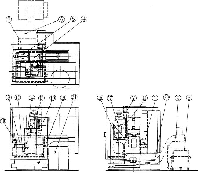
2-2 Component Units
1 |
Oil pressure unit |
7 |
Z axis feed motor |
13 |
Turret |
19 |
Bed |
|
|
|
|
|
|
|
|
2 |
Coolant tank |
8 |
Chip box (OP) |
14 |
Q-setter |
20 |
Spindle cooling |
|
|
|
|
|
|
|
system |
|
|
|
|
|
|
|
|
3 |
X axis feed motor |
9 |
Chip conveyor(OP) |
15 |
Spindle |
21 |
Stoker |
|
|
|
|
|
|
|
|
4 |
Saddle |
10 |
Operating panel |
16 |
|
|
|
|
|
|
|
|
|
|
|
5 |
Coolant pump |
11 |
Cross slide |
17 |
Headstock |
|
|
|
|
|
|
|
|
|
|
6 |
Power control cabinet |
12 |
Tool post |
18 |
Chuck pressure |
|
|
|
|
|
|
|
adjustment manifold |
|
|
2 - 2
2-3 Machine Specifications
1.Machine Specifications 1) CS20
|
Item |
|
|
Unit |
12-st. base holder |
12-st. VDI type |
12-st. VDI rotating |
||
|
|
|
|
|
|
type turret |
turret |
|
tool type turret |
Capacity |
Max. spindle swing |
mm (inch) |
|
350 (13.8”) |
|
|
|||
|
|
|
|
|
|
|
|
|
|
|
Chuck outer diameter |
mm (inch) |
|
210 (8.25”) |
|
|
|||
|
|
|
|
|
|
|
|
||
|
Max. machining diameter |
mm (inch) |
|
φ 350 (φ 13.8”) |
|||||
|
|
|
|
|
|
|
|
|
|
|
Max. machining length |
mm (inch) |
|
150 (6”) |
|
|
|||
|
|
|
|
|
|
|
|
|
|
Travel |
X axis travel |
|
|
mm (inch) |
1310(51.5”)(Cutting area:190 |
||||
|
|
|
(7.5”),Loader area:1120 (44”)) |
||||||
|
|
|
|
|
|
||||
|
|
|
|
|
|
|
|
|
|
|
Z axis travel |
|
|
mm (inch) |
|
370 (14.5”) |
|
|
|
|
|
|
|
|
|
|
|
|
|
Spindle |
Spindle speed |
|
|
min-1 (rpm) |
|
30 ~ 5000 |
|
|
|
|
Spindle speed range |
|
|
Stepless |
|
|
|||
|
|
|
|
|
|
|
|
|
|
|
Spindle nose (Type, NO.) |
JIS |
|
A2-6 |
|
|
|||
|
|
|
|
|
|
|
|
|
|
|
Diameter of spindle through |
mm(inch) |
|
φ 59 (φ 2.3”) |
|
|
|||
|
hole |
|
|
|
|
|
|||
|
|
|
|
|
|
|
|
||
|
|
|
|
|
|
|
|
|
|
|
Spindle bearing inside |
mm (inch) |
|
φ 100 (φ 4”) |
|
|
|||
|
diameter |
|
|
|
|
|
|||
|
|
|
|
|
|
|
|
||
|
|
|
|
|
|
|
|
|
|
Turret |
Type of turret |
|
|
|
12-st. base holder |
12-st. VDI |
|
12-st. VDI |
|
|
|
|
|
rotating tool |
|||||
head |
No. of tool |
|
|
|
12 pcs.(O.D. 6, I.D. 6) |
|
12 |
||
|
|
|
|
|
|
|
|
|
|
|
Shank size of O.D. tool |
mm (inch) |
|
25 (1”) |
|
|
|||
|
|
|
|
|
|
|
|
|
|
|
Boring ber size |
|
|
mm (inch) |
32(B/H hole dia. 40) / |
||||
|
|
|
1-1/4” (HOLE 1.5”) |
||||||
|
|
|
|
|
|
||||
|
|
|
|
|
|
|
|
|
|
Feedrate |
Rapid traverse |
|
X axis |
m/min (ipm) |
|
30 (1181) |
|
|
|
|
|
|
|
|
|
|
|
|
|
|
|
|
|
Z axis |
m/min (ipm) |
|
30 (1181) |
|
|
|
|
|
|
|
|
|
|||
|
Cutting feed (Per revolution) |
mm/rev (ipr) |
0.001 ~ 1000 (0.001 ~ 40) |
||||||
|
|
|
|
|
|
|
|
|
|
|
Jog feed |
|
|
mm/min (ipm) |
0 ~ 5000 (0 ~ 200) |
||||
|
|
|
|
|
|
|
|
|
|
Motor |
Spindle motor |
|
|
AC-kW (HP) |
|
11/7.5 (15/10) |
|||
|
(40%ED/continuous) |
|
|||||||
|
|
|
|
|
|
||||
|
|
|
|
|
|
|
|
||
|
For Rotary tools(15 minutes |
AC-kW (HP)E |
---- |
---- |
|
3.7/2.2(5/3) |
|||
|
rated/continuous) |
|
|||||||
|
|
|
|
|
|
||||
|
|
|
|
|
|
|
|
|
|
|
Axis feed motor |
|
X axis |
AC-kW(HP) |
|
2.8 (3.8) |
|
|
|
|
|
|
|
|
|
|
|
|
|
|
|
|
|
Z axis |
AC-kW (HP) |
|
3.8 ( 5 ) |
|
|
|
|
|
|
|
|
|
|
||
|
Turret indexing motor |
kW (HP) |
|
2.2 (2.9) |
|
|
|||
|
|
|
|
|
|
|
|
||
|
Oil pressure pump |
kW (HP) |
|
0.4 (0.5) |
|
|
|||
|
|
|
|
|
|
|
|
||
|
Coolant fluid motor |
kW (HP) |
|
1.1 (1.5) |
|
|
|||
|
|
|
|
|
|
|
|
||
|
Spindle coolant pump |
W (HP) |
|
0.4 (0.5) |
|
|
|||
|
|
|
|
|
|
|
|
|
|
Power |
Power supply |
|
|
kVA |
|
23 |
|
|
|
|
|
|
|
|
|
|
|
|
|
Source |
Pneumatic |
Pressure |
MPa (psi) |
|
0.5 (70) |
|
|
||
|
|
|
|
|
|
|
|
|
|
|
source |
Rate of flow |
N /min (gal/min) |
|
150 (40) |
|
|
||
|
|
|
|
|
|
|
|
|
|
Machine |
|
|
|
|
kg ( bs) |
|
5000 (11000) |
||
weight |
|
|
|
|
|
||||
|
|
|
|
|
|
|
|
|
|
|
|
|
|
|
|
|
|
|
|
|
|
|
|
|
2 - 3 |
|
|
|
|

2) CS25
|
Item |
|
|
Unit |
12-st. base holder |
12-st. VDI type |
12-st. VDI rotating |
|||
|
|
|
|
|
|
type turret |
turret |
|
tool type turret |
|
Capacity |
Max. spindle swing |
mm (inch) |
|
|
350 (13.8”) |
|
|
|||
|
|
|
|
|
|
|
|
|
|
|
|
Chuck outer diameter |
mm (inch) |
|
|
254 (10”) |
|
|
|||
|
|
|
|
|
|
|
|
|
|
|
|
Max. machining diameter |
mm (inch) |
|
|
φ 350 (φ 13.8”) |
|||||
|
|
|
|
|
|
|
|
|
|
|
|
Max. machining length |
mm (inch) |
|
|
150 (6”) |
|
|
|||
|
|
|
|
|
|
|
|
|
|
|
Travel |
X axis travel |
|
|
mm (inch) |
1310(51.5”)(Cutting area:190 |
|||||
|
|
|
(7.5”),Loader area:1120 (44”)) |
|||||||
|
|
|
|
|
|
|||||
|
|
|
|
|
|
|
|
|
|
|
|
Z axis travel |
|
|
mm (inch) |
|
|
370 (14.6”) |
|
|
|
|
|
|
|
|
|
|
|
|
|
|
Spindle |
Spindle speed |
|
|
min-1 (rpm) |
|
|
30 ~ 4000 |
|
|
|
|
Spindle speed range |
|
|
|
Stepless |
|
|
|||
|
|
|
|
|
|
|
|
|
|
|
|
Spindle nose (Type, NO.) |
JIS |
|
|
A2-8 |
|
|
|||
|
|
|
|
|
|
|
|
|
|
|
|
Diameter of spindle through |
mm(inch) |
|
|
φ 78 (φ 3.1”) |
|
|
|||
|
hole |
|
|
|
|
|
|
|||
|
|
|
|
|
|
|
|
|
||
|
|
|
|
|
|
|
|
|
|
|
|
Spindle bearing inside |
mm (inch) |
|
|
φ 130 (φ 5.1”) |
|||||
|
diameter |
|
|
|
|
|||||
|
|
|
|
|
|
|
|
|
||
|
|
|
|
|
|
|
|
|
|
|
Turret |
Type of turret |
|
|
|
12-st. base holder |
12-st. VDI |
|
12-st. VDI |
||
|
|
|
|
rotating tool |
||||||
head |
No. of tool |
|
|
|
12 pcs.(O.D. 6, I.D. 6) |
|
12 |
|||
|
|
|
|
|
|
|
|
|
|
|
|
Shank size of O.D. tool |
mm (inch) |
|
|
25 (1”) |
|
|
|||
|
|
|
|
|
|
|
|
|
|
|
|
Boring ber size |
|
|
mm (inch) |
32(B/H hole dia. 40) / |
|||||
|
|
|
1-1/4” (HOLE 1.5”) |
|||||||
|
|
|
|
|
|
|||||
|
|
|
|
|
|
|
|
|
|
|
Feedrate |
Rapid traverse |
|
X axis |
m/min (ipm) |
|
|
30 (1181) |
|
|
|
|
|
|
|
|
|
|
|
|
|
|
|
|
|
|
Z axis |
m/min (ipm) |
|
|
30 (1181) |
|
|
|
|
|
|
|
|
|
|
|
||
|
Cutting feed (Per revolution) |
mm/rev (ipr) |
0.001 ~ 1000 (0.001 ~ 40) |
|||||||
|
|
|
|
|
|
|
|
|
|
|
|
Jog feed |
|
|
mm/min (ipm) |
0 ~ 5000 (0 ~ 200) |
|||||
|
|
|
|
|
|
|
|
|
|
|
Motor |
Spindle motor |
|
|
AC-kW (HP) |
15/18.5 (25/20) |
|||||
|
(40%ED/continuous) |
|||||||||
|
|
|
|
|
|
|
||||
|
|
|
|
|
|
|
|
|
||
|
For Rotary tools(15 minutes |
AC-kW (HP)E |
---- |
|
---- |
3.7/2.2(5/3) |
||||
|
rated/continuous) |
|
||||||||
|
|
|
|
|
|
|
||||
|
|
|
|
|
|
|
|
|
|
|
|
Axis feed motor |
|
X axis |
AC-kW(HP) |
|
|
2.8 (3.8) |
|
|
|
|
|
|
|
|
|
|
|
|
|
|
|
|
|
|
Z axis |
AC-kW (HP) |
|
|
3.8 ( 5 ) |
|
|
|
|
|
|
|
|
|
|
|
||
|
Turret indexing motor |
kW (HP) |
|
|
2.2 (2.9) |
|
|
|||
|
|
|
|
|
|
|
|
|
||
|
Oil pressure pump |
kW (HP) |
|
|
0.4 (0.5) |
|
|
|||
|
|
|
|
|
|
|
|
|
||
|
Coolant fluid motor |
kW (HP) |
|
|
1.1 (1.5) |
|
|
|||
|
|
|
|
|
|
|
|
|
||
|
Spindle coolant pump |
W (HP) |
|
|
0.4 (0.5) |
|
|
|||
|
|
|
|
|
|
|
|
|
|
|
Power |
Power supply |
|
|
kVA |
|
|
26 |
|
|
|
|
|
|
|
|
|
|
|
|
|
|
Source |
Pneumatic |
Pressure |
MPa (psi) |
|
|
0.5 (70) |
|
|
||
|
|
|
|
|
|
|
|
|
|
|
|
source |
Rate of flow |
N /min (gal/min) |
|
|
150 (40) |
|
|
||
|
|
|
|
|
|
|
|
|
|
|
Machine |
|
|
|
|
kg ( bs) |
|
|
5400 (11900) |
||
weight |
|
|
|
|
|
|
||||
|
|
|
|
|
|
|
|
|
|
|
|
|
|
|
|
|
|
|
|
|
|
|
|
|
|
|
2 - 4 |
|
|
|
|
|
2.Standard Accessories
1. |
Q-Setter ........................................................................ |
1 set |
2. |
CS20: φ 210 Solid chuck (With chuck open/close |
|
|
confirmation equipment) ............................................... |
1 set |
|
CS25: φ 254 Solid chuck (With chuck open/close |
|
|
confirmation equipment) ............................................... |
1 set |
3. |
Soft jaw ......................................................................... |
1 set |
4. |
Work light ...................................................................... |
1 set |
5. |
Leveling block ............................................................... |
1 set |
6. |
Spindle override ............................................................ |
1 set |
7. |
Call light (yellow) ........................................................... |
1 set |
8. |
Spindle load meter (on screen) ..................................... |
1 set |
9. |
Electric leakage breaker ............................................... |
1 set |
10. |
Spindle positioning device (two position indexing electric |
|
|
system) ......................................................................... |
1 set |
11 |
Chuck side air blow confirmation .................................. |
1 set |
12 |
Jet coolant .................................................................... |
1 set |
13 |
Operator side door interlock ......................................... |
1 set |
14 |
Chuck open/close M function ........................................ |
1 set |
15 |
Chuck open/close confirmation .................................... |
1 set |
16 |
Spindle speed meter (on screen) .................................. |
1 set |
17 |
Machining completion pre-call ...................................... |
1 set |
18 |
Work counter (on screen) ............................................. |
1 set |
19 |
Run hour display (on screen) ........................................ |
1 set |
20 |
Spinners & wrenches .................................................... |
1 set |
3.Optional Accessories
• |
Chip conveyor backward delivery |
• |
External power transformer 32 kVA |
• |
Chip wagon |
• |
Work tools |
• |
Automatic power shut-off device |
• |
Coolant gun |
• |
SEIKI DON FD card |
• |
Tool post coolant/air changeover (M-code) |
• |
Magnet piece (In the coolant tank) |
• |
Chucking pressure 2-step changeover |
• |
Chip conveyor intermittent feeder |
• |
Work pusher |
• |
Chuck-side coolant/air changeover (M-code) • |
Spindle tachometer (Standalone) |
|
• |
Work airtightness checker |
• |
Rotary tool tachometer (Standalone) |
• |
Counter |
• |
Spindle load meter (Standalone) |
• |
Addition of the call light |
• |
Rotary tool spindle load meter (Standalone) |
• |
Buzzer alarm |
• |
Weekly timer |
•Safety measure specifications
2 - 5
2-4 NC Unit Specifications
Refer to the NC unit specifications list of SEIKI SEICOS instruction manual (operating section) for details of specifications.
Item |
|
Standard specification |
1 |
Controlled axis |
2 axis, axis simultaneous |
|
|
|
2 |
Least input increment |
0.001mm/0.0001” |
|
|
|
3 |
Interpolation |
Positioning, Linear, Circular |
|
|
|
4 |
Inch/Metric conversion |
|
|
|
|
5 |
Tape code |
EIA/ISO auto.recognition |
|
|
|
6 |
Designation |
INC./ABS. |
|
|
|
7 |
Decimal point programming |
|
|
|
|
8 |
Buffer register |
|
|
|
|
9 |
Feedrate command |
F code/feedrate direct |
|
|
|
10 |
Rapid traverse override |
0, 1, 10, 50, 100% |
|
|
|
11 |
Feedrate override |
0~200% (10% step) |
|
|
|
12 |
Override cancel |
|
|
|
|
13 |
Spindle override |
50~150% (10% step) |
|
|
|
14 |
Threading function |
F/E code direct |
|
|
|
15 |
Manual feed function |
Rapid, Jog feed, Handle |
|
|
|
16 |
Manual pulse generator |
× 1, × 10, × 100 (inch=× 50) |
17 |
Part program storage |
80m |
|
|
|
18 |
Add. registered programs |
100 pcs. |
|
|
|
19 |
Back ground editing |
|
|
|
|
20 |
Extended program edit |
(Program copy) |
|
|
|
21 |
Display |
9.5" Monochrome |
|
|
|
22 |
Memory lock |
|
|
|
|
23 |
Language display |
English/German |
|
|
|
24 |
Tape mode operation |
RS232C*1 |
25 |
I/O interface |
RS232C*1 |
26 |
Function |
G3, M3, T4 |
|
|
|
27 |
Spindle speed command |
S code/speed direct |
|
|
|
28 |
Constant surface speed control |
|
|
|
|
2 - 6
Item |
|
Standard specification |
|
|
|
|
|
29 |
Automatic tool nose radius |
|
|
|
compensation |
|
|
|
|
|
|
30 |
Grooving width offset |
|
(I.D., O.D., Face) |
|
|
|
|
31 |
Tool offsets |
|
32 sets |
|
|
|
|
32 |
Q-setter repeat function |
|
|
|
|
|
|
33 |
Cutting point coordinate system |
|
|
|
setting |
|
|
|
|
|
|
34 |
Reference point return |
|
Manual, Auto G27~29 |
|
|
|
|
35 |
2nd reference point return |
|
G30 |
|
|
|
|
36 |
Graphic display |
|
Before and synchronized machining |
|
|
|
|
37 |
16-character program name |
|
|
|
|
|
|
38 |
Single block |
|
|
|
|
|
|
39 |
Block skip |
|
Total 9 pcs. (with switch 5 pcs.) |
|
|
|
|
40 |
Optional stop |
|
|
|
|
|
|
41 |
Program check function |
|
Dry run + Spindle stop + coolant stop |
|
|
|
|
42 |
Machine lock |
|
|
|
|
|
|
43 |
Program number |
|
O 8 digit |
|
|
|
|
44 |
Program number search |
|
|
|
|
|
|
45 |
Sequence number search, |
|
|
|
Sequence number comparison |
|
|
|
|
|
|
46 |
Program comparison |
|
|
|
|
|
|
47 |
Manual absolute |
|
[ON] fixed |
|
|
|
|
48 |
Custom macro |
|
Common variable 300 pcs. |
|
|
|
|
49 |
Soft jaws forming function |
|
|
|
by graphic |
|
|
|
|
|
|
50 |
Fixed cycle |
|
G90, G92, G94 |
|
|
|
|
51 |
Multiple repetitive cycle |
|
G70~G76 |
|
|
|
|
52 |
Mirror image |
|
Setting via screen |
|
|
|
|
53 |
Chamfering/corner R any angle |
|
|
|
|
|
|
54 |
Radius designation on arc |
|
|
|
|
|
|
55 |
Exact stop |
|
G09 G61 G64 |
|
|
|
|
56 |
Programmable data input |
|
G10 |
|
|
|
|
2 - 7
Item |
|
Standard specification |
|
|
|
57 |
Backlash compensation |
|
|
|
|
58 |
Run hour display/Spindle |
(On screen) |
|
speed display |
|
|
|
|
59 |
Cycle completion pre-call |
(On screen) |
|
|
|
60 |
Cycle time display |
(On screen) |
|
|
|
61 |
Work counter |
(On screen) |
|
|
|
62 |
Following up |
|
|
|
|
63 |
Stored stroke limit 1• 2• 3 |
|
|
|
|
64 |
NC self diagnostics |
|
|
|
|
|
*1 : Interface only. |
|
|
Not include cable. |
|
2 - 8
Item |
|
Optional specification |
1 |
Direct tapping |
(Rotating tool) |
|
|
|
2 |
Variable lead threading |
|
|
|
|
3 |
Thread cutting cycle retract |
|
|
|
|
4 |
Multiple start thread cutting |
|
|
|
|
5 |
Custom macro |
Common variable 600 pcs. |
|
|
|
6 |
Drilling cycle |
(Rotating tool) G80~89 |
|
|
|
7 |
Macro print func. |
(Need printer w/ RS232C I/F) *1 |
8 |
Tool diameter compensation |
(Rotating tool) |
|
|
|
9 |
Part program storage |
Total 160 m |
|
|
|
10 |
Part program storage |
Total 320 m |
|
|
|
11 |
Add. registerable prog. |
Total 200 pcs. (Need 160m) |
|
|
|
12 |
Add. registerable prog. |
Total 400 pcs. (Need 320m) |
|
|
|
13 |
Tool offset |
Total 64 pcs. |
|
|
|
14 |
Tool offset |
Total 99 pcs. |
|
|
|
15 |
Return to cycle interrupted |
|
|
point |
|
|
|
|
16 |
48-character program name |
|
|
|
|
17 |
Program restart |
|
|
|
|
18 |
Angle program for linear |
|
|
interpolation |
|
|
|
|
19 |
Cylindrical interpolation |
(Including tool diameter compensation) |
|
|
|
20 |
Polar coordinate interpolation |
(Including tool diameter compensation) |
|
|
|
21 |
External data input |
Need technical discussion |
|
|
|
22 |
Skip function |
High-speed |
|
|
|
23 |
Tool life management (Count |
|
|
only)/Spare tool call |
|
|
|
|
24 |
Each program, cycle time |
10 pcs. (On screen) |
|
display |
|
|
|
|
25 |
Each program, cycle time |
50 pcs. (On screen) |
|
display |
|
|
|
|
26 |
Cutting monitor |
(Incl. tool llife management (Count only) / Spare tool call) |
|
|
|
27 |
C-axis control |
(Rotating tool and C-axis must needed) *2 |
28 |
Multiple axis control |
*2 |
*1 : Interface only. Not include cable.
*2 : When selected C axis must choose multiple axis control
2 - 9
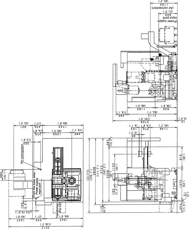
2-5 Major Dimensions
1.CS20/25 Major Dimension
(1) 12-station Base Holder Turret Head Type
Dimension : metric (mm)
inch (”)
2 - 10

(2) 12-station VDI/VDI Rotating Tool Turret Type
Dimension : metric (mm)
inch (”)
2 - 11
 Loading...