


SEIKI - SEICOS
å10/16/18/21 INSTRUCTION MANUAL
MAINTENANCE
41 Edition 1.01 11-2000
Hitachi Seiki Deutschland
Werkzeugmaschinen GmbH
CONTENTS
I-I SEICOS Σ 10 UNIT ............................................................................. |
1 - 2 |
|
1. OVERVIEW ......................................................................................................................... |
1 - 3 |
|
2. FUNCTIONS AND HANDLING OF CONTROL UNITS ......................................................... |
1 - 7 |
|
3. TROUBLESHOOTING ...................................................................................................... |
1 - 24 |
|
4. POWER-ON ADJUSTMENT ............................................................................................. |
1 - 25 |
|
5. DAILY MAINTENANCE AND INSPECTION ........................................................................ |
1 - 29 |
|
I-II SEICOS Σ 16/18/21 UNIT ................................................................ |
1 - 32 |
|
1. OVERVIEW ....................................................................................................................... |
1 - 33 |
|
2. PCB CONNECTORS AND CARD CONFIGURATION ...................................................... |
1 - 37 |
|
3. TROUBLESHOOTING ...................................................................................................... |
1 - 50 |
|
4. POWER-ON ADJUSTMENT ............................................................................................. |
1 - 51 |
|
5. DAILY MAINTENANCE AND INSPECTION ........................................................................ |
1 - 55 |
|
I-III RS-232C INTERFACE SPECIFICATION ....................................... |
1 - 62 |
|
II. ALARM LIST ....................................................................................... |
2 - 1 |
|
1. Alarms Related to Program and Operation .......................................................................... |
2 - 2 |
|
2. Alarms Related to Absolute Pulse Coder (APC) ................................................................ |
2 - 50 |
|
3. Alarms Related to Serial Pulse Coder (SPC) .................................................................... |
2 - 52 |
|
4. Alarms Related to Servo .................................................................................................... |
2 - 56 |
|
5. Alarms Related to Overtravel ............................................................................................. |
2 - 67 |
|
6. Alarms Related to Overheat ............................................................................................... |
2 - 69 |
|
7. Alarms Related to Direct Tap ............................................................................................. |
2 - 70 |
|
8. Alarms Related to Serial Spindle ........................................................................................ |
2 - 71 |
|
9. System Alarms .................................................................................................................. |
2 - 73 |
|
III. PARAMETERS ................................................................................... |
3 - 1 |
|
1. DISPLAY, SETTING, AND OUTPUT OF PARAMETERS...................................................... |
3 - 2 |
|
2. DESCRIPTION OF PARAMETERS..................................................................................... |
3 - 5 |
|
2.1 |
Parameters Related to Communication (RS-232C) (No. 0100 onward) ...................... |
3 - 8 |
2.2 |
Parameters Related to Axis Control/Input Increment ................................................. |
3 - 17 |
2.3 |
Parameters Related to Coordinate System ............................................................... |
3 - 26 |
2.4 |
Parameters Related to Stroke Limit ........................................................................... |
3 - 33 |
2.5 |
Parameters Related to Chuck Tail Stock Barrier (L-system) ..................................... |
3 - 37 |
2.6 |
Parameters Related to Feed Rate ............................................................................. |
3 - 41 |
2.7 |
Parameters Related to Acceleration/Deceleration Control ......................................... |
3 - 49 |
2.8 |
Parameters Related to Servo..................................................................................... |
3 - 68 |
2.9 |
Parameters Related to DI/DO .................................................................................... |
3 - 91 |
2.10 Parameters Related to CRT/MDI, Display, and Editing ............................................ |
3 - 96 |
|
i
2.11 |
Parameters Related to Program ............................................................................ |
3 - 105 |
2.12 |
Parameters Related to Pitch Error Compensation ................................................ |
3 - 121 |
2.13 |
Parameters Related to Spindle Control .................................................................. |
3 - 125 |
2.14 |
Parameters Related to Tool Offset ......................................................................... |
3 - 164 |
2.15 |
Parameters Related to Canned Cycle ................................................................... |
3 - 172 |
2.16 |
Parameters Related to Direct Tap .......................................................................... |
3 - 191 |
2.17 |
Parameters Related to Custom Macro .................................................................. |
3 - 201 |
2.18 |
Parameters Related to Skip Function .................................................................... |
3 - 209 |
2.19 |
Parameters Related to Measurement .................................................................... |
3 - 212 |
2.20 |
Parameters Related to Graphic Display ................................................................. |
3 - 226 |
2.21 |
Parameters Related to Manual Handle Feed, Manual Handle Interrupt, |
|
|
and Tool Axis Direction Handle Feed...................................................................... |
3 - 232 |
2.22 |
Parameters Related to Polygon Machining (L-system Only) ................................. |
3 - 235 |
2.23 |
Parameters Related to Cutting Monitoring ............................................................. |
3 - 239 |
2.24 |
Parameters Related to High-speed, High-accuracy Contour Control by RISC ...... |
3 - 248 |
2.25 |
Other Parameters .................................................................................................. |
3 - 255 |
2.26 |
Parameters Related to Maintenance ...................................................................... |
3 - 277 |
IV. DIAGNOSE4 - 1 |
|
|
1. DIAGNOSE DISPLAY .......................................................................................................... |
4 - 2 |
|
1.1 |
Input/Output Signals ..................................................................................................... |
4 - 3 |
APPENDIX: BOOT SYSTEM ................................................................. |
A - 1 |
|
1. OVERVIEW ......................................................................................................................... |
A - 2 |
|
1.1 |
Starting up the BOOT SYSTEM ................................................................................... |
A - 3 |
1.2 |
System Files and User Files ........................................................................................ |
A - 3 |
2. SCREEN CONFIGURATION AND OPERATING METHODS .............................................. |
A - 4 |
|
2.1 |
SYSTEM DATA LOADING Screen ................................................................................ |
A - 5 |
2.2 |
SYSTEM DATA CHECK Screen ................................................................................... |
A - 7 |
2.3 |
SYSTEM DATA DELETE Screen ................................................................................. |
A - 8 |
2.4 |
SYSTEM DATA SAVE Screen ...................................................................................... |
A - 9 |
2.5 |
SRAM DATA BACKUP Screen ................................................................................... |
A - 11 |
2.6 |
MEMORY CARD FILE DELETE Screen .................................................................... |
A - 14 |
2.7 |
MEMORY CARD FORMAT Function ......................................................................... |
A - 14 |
2.8 |
LOAD BASIC SYSTEM .............................................................................................. |
A - 15 |
3. ERROR MESSAGES AND REMEDIES ............................................................................ |
A - 17 |
|
ii
MAINTENANCE
I-I SEICOS Σ 10 UNIT
I-II SEICOS Σ 16/18/21 UNIT
I-III RS-232C INTERFACE SPECIFICATION
II.ALARMS LIST
III.PARAMETERS
IV. DIAGNOSE
1 - 1
I-I SEICOS Σ 10 UNIT
1.OVERVIEW
1.1System Configuration
1.2Component Units List
2.FUNCTIONS AND HANDLING OF CONTROLLER
2.1Power Unit
2.2CPU Board
2.3Option-1 Board (DNC)
2.4Option-3 Board (PMC)
2.564-bit RISC Board (RISC)
2.6MMC-IV Board (MMC-TV)
2.7Liquid Crystal Display (LCD)
2.8Data Server Board
2.9List of Units and Print Boards
3.TROUBLESHOOTING
3.1Tracking through the ALARM Screen
3.2Tracking through the Controller’s Monitor
4.POWER-ON ADJUSTMENT
4.1Power-on Procedure
4.2System Table
4.3SLBUS Table
5.DAILY MAINTENANCE AND INSPECTION
5.1Replacing the Battery
1 - 2

1. OVERVIEW
The SEICOS Σ 10 CNC unit is a compact high-reliability unit provided with up-to-date device technologies. In the M-system, it enables high-speed, high-accuracy machining by using 64-bit RISC.
1.1 System Configuration
The following figure shows a system example using the SEICOS Σ 10 CNC unit.
CRT NC Operation Panel
Machine Operation Panel |
I/O Slave |
Manual Pulse Generator
CNC Unit
SLBUS
Distribution
Board
SLBUS Conversation
Module
200 V AC
Power
Unit
Spindle |
Servo |
Servo |
Servo |
Motor |
Amp. |
Amp. |
Amp. |
Spindle |
Servo |
Servo |
Servo |
Amp. |
Motor |
Motor |
Motor |
1 - 3
1.2 Component Units List
The following table lists the component units of the controller. A mounting position of each unit is fixed as shown in the mounting drawing. All the component units are plug-in type and can be easily replaced.
(1) Unit list
Name |
Symbol |
Function/Usage |
|
|
|
Power unit |
PSU |
ON/OFF control |
|
|
|
CPU board |
MAIN |
Main CPU |
|
|
|
PMC board |
PMC |
Sequence control |
|
|
|
I/O board |
I/O |
High-speed skip |
|
|
|
RISC board |
RISC |
High-accuracy profile control (for M) |
|
|
|
DNC board |
DNC |
DNC operation |
|
|
|
(Note) The PMC board may be called an “option-3 board,” and DNC board an “option- 1 board,” respectively.
1 - 4
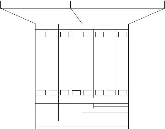
(2) SEICOS Σ 10 unit configuration
|
|
|
|
DMC |
|
RISC |
|
I/O |
|
PMC |
|
CPU |
|
Power |
||||||||||||
|
|
|
|
Board |
|
Board |
|
Board |
|
Board |
|
Board |
|
Unit |
||||||||||||
|
|
|
|
|
|
|
|
|
|
|
|
|
|
|
|
|
|
|
|
|
|
|
|
|
|
|
|
|
|
|
Communica- |
|
RISC |
|
|
|
|
|
PMC |
|
CNC |
|
|
|
|
||||||||
|
|
|
|
tion CPU |
|
CPU |
|
|
|
|
|
CPU |
|
CPU |
|
|
|
|
||||||||
|
|
|
|
|
|
|
|
|
|
|
|
|
|
|
|
|
|
|
|
|
|
|
|
|
|
|
|
|
|
|
Remote |
|
High- |
|
High- |
|
PMC-RC3/4 |
|
Servo 6 |
|
ON/OFF |
||||||||||||
|
|
|
|
Buffer |
|
accuracy |
|
Speed |
|
I/O LINK |
|
Axes, |
|
Control |
||||||||||||
|
|
|
|
|
|
|
|
Spindle |
|
|||||||||||||||||
|
|
|
|
DNC1 |
|
Profile |
|
Skip |
|
|
|
|
|
|
|
|
|
|||||||||
|
|
|
|
|
|
|
|
|
|
|
Interface, |
|
|
|
|
|||||||||||
|
|
|
|
DNC2 |
|
Control |
|
|
|
|
|
|
|
|
|
CRT, |
|
|
|
|
||||||
|
|
|
|
|
|
|
|
|
|
|
|
|
|
|
|
|
|
|
|
Keyboard, |
|
|
|
|
||
|
|
|
|
|
|
|
|
(for M) |
|
|
|
|
|
|
|
|
|
RS-232C*2 |
|
|
|
|
||||
|
|
|
|
|
|
|
|
|
|
|
|
|
|
|
|
|
Memory |
|
|
|
|
|||||
|
|
|
|
|
|
|
|
|
|
|
|
|
|
|
|
|
|
|
|
Card, |
|
|
|
|
||
|
|
|
|
|
|
|
|
|
|
|
|
|
|
|
|
|
|
|
|
Manual |
|
|
|
|
||
|
|
|
|
|
|
|
|
|
|
|
|
|
|
|
|
|
|
|
|
Handle |
|
|
|
|
||
|
|
|
|
|
|
|
|
|
|
|
|
|
|
|
|
(Note) |
|
PMC-RB5/6 |
|
|
|
|
||||
|
|
|
|
|
|
|
|
|
|
|
|
|
|
|
|
|
|
|
|
I/O LINK |
|
|
|
|
||
|
|
|
|
|
|
|
|
|
|
|
|
|
|
|
|
|
|
|
|
|
|
|
|
|
|
|
|
|
|
|
|
|
|
|
|
|
|
|
|
|
|
|
|
|
|
|
|
|
|
|
|
|
|
|
|
|
|
|
|
|
|
|
|
|
|
|
|
|
|
|
|
|
|
|
|
|
|
|
|
|
Optional |
Basic System |
I/O PMC Main Power
CPU CPU Source
(Note)
< |
> 3 |
Slots |
|
< |
> 4 |
Slots |
|
< |
> |
6 |
Slots |
< |
> |
8 |
Slots |
(Note) The PMC board is required when using the “PMC-RC3 or PMC-RC4,” but not required when using the “PMC-RB5 or PMC-RB6.” [The PMC function is incorporated in the main CPU board.]
1 - 5
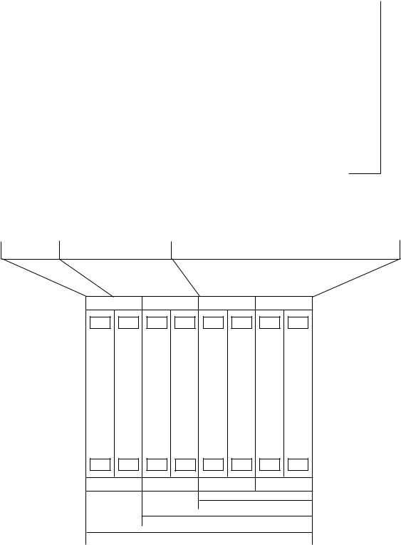
(3) |
SEICOS Σ 10 Multi unit configuration |
|
|
|
|
|
|
|
|
|
|
|
|
|
|
||||||||||||||
|
|
|
|
|
|
|
|
|
|
|
|
|
|
|
|
|
|
|
|
|
|
|
|
|
|
|
|
|
|
MMC |
|
|
DMC |
|
RISC |
|
I/O |
|
PMC |
|
CPU |
|
|
Power |
|||||||||||||||
Board |
|
|
Board |
|
Board |
|
Board |
|
Board |
|
Board |
|
|
|
Unit |
||||||||||||||
|
|
|
|
|
|
|
|
|
|
|
|
|
|
|
|
|
|
|
|
|
|
|
|
|
|
|
|
|
|
MMC-IV |
|
|
Communi- |
|
RISC |
|
|
|
|
|
PMC |
|
CNC |
|
Gra- |
||||||||||||||
CPU |
|
|
cation CPU |
|
CPU |
|
|
|
|
|
CPU |
|
CPU |
|
phic |
||||||||||||||
|
|
|
|
|
|
|
|
|
|
|
|
|
|
|
|
|
|
|
|
|
|
|
|
|
Board |
|
|
||
HDD |
|
|
Remote |
|
High- |
|
High- |
|
PMC-RC3/4 |
|
Servo 6 |
|
ON/OFF |
|
|||||||||||||||
FDD |
|
|
Buffer |
|
accuracy |
|
speed |
|
I/O LINK |
|
Axes, |
|
|
|
|
Control |
|||||||||||||
|
|
|
|
|
|
Spindle |
|
|
|
|
|||||||||||||||||||
|
|
|
|
|
DNC1 |
|
Profile |
|
Skip |
|
|
|
|
|
|
|
|
|
|
|
|||||||||
PRT |
|
|
|
|
|
|
|
|
|
Interface, |
|
|
|
|
|
|
|||||||||||||
Keyboard |
|
|
DNC2 |
|
Control |
|
|
|
|
|
|
|
|
|
CRT, |
|
|
|
|
|
|
||||||||
|
|
|
|
|
|
|
|
|
|
|
|
|
|
|
|
|
|
Keyboard, |
|
|
|
|
|
|
|||||
|
|
|
|
|
|
|
|
|
|
|
|
|
|
|
|
|
|
|
|
|
|
|
|
|
|
|
|||
RS232C |
|
|
|
|
|
|
|
|
|
|
|
|
|
|
|
|
|
|
RS-232C*2, |
|
|
|
|
|
|
||||
|
|
|
|
|
|
|
|
|
|
|
|
|
|
|
|
|
|
|
|
|
Memory |
|
|
|
|
|
|
||
|
|
|
|
|
(for M) |
|
|
|
|
|
|
|
|
|
|
|
|
|
Card, |
|
|
|
|
|
|
||||
|
|
|
|
|
|
|
|
|
|
|
|
|
|
|
|
|
|
|
|
|
Manual |
|
|
|
|
|
|
||
|
|
|
|
|
|
|
|
|
|
|
|
|
|
|
|
|
|
|
|
|
Handle |
|
|
|
|
|
|
||
|
|
|
|
|
|
|
|
|
|
|
|
|
|
|
|
|
(Note) |
|
PMC-RB5/6 |
|
|
|
|
|
|
||||
|
|
|
|
|
|
|
|
|
|
|
|
|
|
|
|
|
|
|
|
|
I/O LINK |
|
|
|
|
|
|
||
|
|
|
|
|
|
|
|
|
|
|
|
|
|
|
|
|
|
|
|
|
|
|
|
|
|
|
|
|
|
|
|
|
|
|
|
|
|
|
|
|
|
|
|
|
|
|
|
|
|
|
|
|
|
|
|
|
|
|
|
|
|
|
|
|
|
|
|
|
|
|
|
|
|
|
|
|
|
|
|
|
|
|
|
|
|
|
|
|
|
Basic |
Optional |
Basic System |
I/O PMC Main Power
CPU CPU Source
( ’ • )
< |
> 4 |
Slots |
|
< |
> |
6 |
Slots |
< |
> |
8 |
Slots |
(Note) The PMC board is required when using the “PMC-RC3 or PMC-RC4,” but not required when using the “PMC-RB5 or PMC-RB6.” [The PMC function is incorporated in the main CPU board.]
1 - 6
2. FUNCTIONS AND HANDLING OF CONTROL UNITS
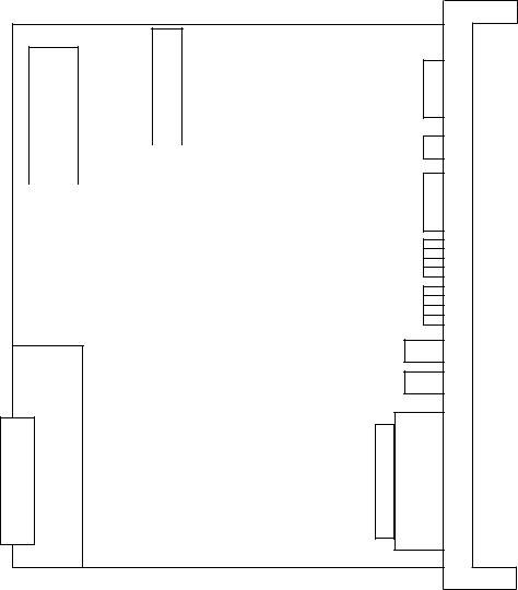
2.1 Power Unit (PSU)
This unit supplies DC power to each control unit.
Name |
Type |
|
|
Power Unit AI |
A16B-1212-0901 |
|
|
Power Unit BI |
A16B-1212-0871 |
|
|
Graphic Board [MULTI Specification Only]
CP1
(ACIN)
F1
CP2 |
|
|
CP3 |
|
|
||
(ACOUT) |
|
|
(ACOUT) |
|
|
|
|
Battery Case
PIL LED
ALM LED
CP4
CONTROL
CP5 CP6 (24V) (24E)
F3 F4
1 - 7
2.1.1 LED Indications
|
Signal |
|
Color |
|
|
|
|
Description |
||||
|
|
|
|
|
|
|
|
|
|
|
|
|
|
|
PIL |
|
Green |
|
Illuminated when an input supply voltage is supplied to the CP1. |
||||||
|
|
|
|
|
|
|
|
|
|
|
|
|
|
|
ALM |
|
Red |
|
Illuminated when a DC output voltage has an overcurrent/ |
||||||
|
|
|
|
|
|
|
overvoltage or drops. |
|
|
|
||
|
|
|
|
|
|
|
|
|
|
|
|
|
2.1.2 FUSE |
|
|
|
|
|
|
|
|
|
|
|
|
(1) |
Type |
|
|
|
|
|
|
|
|
|
||
|
|
|
|
|
|
|
|
|
|
|
||
|
Power Unit |
|
|
Order No. |
Symbol |
|
Ratings |
|
Individual No. |
|||
|
|
|
|
|
|
|
|
|
|
|
|
|
|
|
|
|
|
|
|
|
F1 |
|
7.5A |
A60L-0001-0245#GP75 |
|
|
|
|
|
|
|
|
|
|
|
|
||
|
|
AI |
|
A02B-0200-K100 |
F3 |
|
3.2A |
A60L-0001-0075#3.2 |
||||
|
|
|
|
|
|
|
|
|
|
|
|
|
|
|
|
|
|
|
|
|
F4 |
|
5.0A |
A60L-0001-0046#5.0 |
|
|
|
|
|
|
|
|
|
|
|
|
|
|
|
|
|
|
|
|
|
|
F1 |
|
7.5A |
A60L-0001-0245#GP75 |
|
|
|
|
|
|
|
|
|
|
|
|
||
|
|
BI |
|
A02B-0200-K101 |
F3 |
|
5.0A |
A60L-0001-0075#5.0 |
||||
|
|
|
|
|
|
|
|
|
|
|
|
|
|
|
|
|
|
|
|
|
F4 |
|
5.0A |
A60L-0001-0046#5.0 |
|
|
|
|
|
|
|
|
|
|
|
|
|
|
(2) |
Application |
|
|
|
|
|
|
|
||||
|
|
|
|
|
|
|
|
|
|
|||
|
Symbol |
|
|
|
|
Application |
|
|
|
|||
|
|
|
|
|
|
|
|
|
|
|
||
|
|
F1 |
|
|
AC200V input |
|
|
|
|
|
||
|
|
|
|
|
|
|
|
|
|
|
||
|
|
F3 |
|
|
Indicator |
|
|
|
|
|
||
|
|
|
|
|
|
|
|
|
|
|
||
|
|
F4 |
|
|
Others |
|
|
|
|
|
||
|
|
|
|
|
|
|
|
|
|
|
|
|
1 - 8
2.1.3 SETTING OF GRAPHIC BOARD (A20B-8001-0480)
TM10 B |
A |
TM11 B |
A |
ROM |
~ |
|
|
|
|
|
TM16 B |
|
A |
|
|
|
|
|
|
|
|
|
||
|
TM17 B |
|
A |
TM3 A |
|
B |
|
|
|
|
TM2 A |
|
B |
|
|
|
|
|
||
|
|
|
|
|
||
|
|
|
|
TM1 A |
|
B |
|
|
|
|
|
||
|
|
|
|
|
||
|
|
|
|
|||
|
|
|
|
|
|
|
JNA
JA1A
(OUT)
LCD ADJ.
JA1B (IN)
HS
PHS
STATUS ALARM
JNA
TM1~TM3 |
LCD/CRT switchingA:CRT |
B: LCD (B:Standard setting) |
TM10 |
ROM switching |
A: Standard setting |
LCD ADJ. |
Adjustment in VIDEO output level |
|
HS AB |
Adjustment in NC page HSYNC phase |
A: Standard setting |
012 |
Adjustment in NC page horizontal position |
1: Standard setting |
PHS01234 Fine adjustment in NC page HSYNC phase |
0: Standard setting |
|
•Perform adjustment with “HS AB” and “PHS 01234” when dots slippage causing flicker takes place on switching between an MMC page and an NC page. First, change “PHS 01234” and set it so that no flicker takes place. When adjustment cannot be made even through this, change “HS AB”.
•Use “HS 012” to adjust by one dot when an MMC and an NC page are not equal in their horizontal position.
•Adjust luminance blur with “LCD ADJ.” on the main board for the NC page. For the MMC page, make adjustment with “LCD ADJUST” of the MMC-IV board.
1 - 9
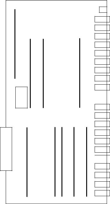
2.2 CPU Board (MAIN)
This is a CNC main CPU board.
Name |
Type |
|
|
S- Σ 10M Main CPU Board |
A16B-3200-0190 |
|
|
S- Σ 10L Main CPU Board |
A16B-3200-0210 |
|
|
LED
|
|
Boot ROM


JA1
JA2
JD5A
JD5B
JA3
JD1A
JA7A
JA8A
JA4A
JS1A
JS2A
JS3A
JS4A
JS5A
JS6A
JF21
JF22
JF23
JF24
JF26
1 - 10

2.2.1 |
List of Modules |
|
|
|
|
|
|
|
|
|
|
|
|
|
|
No. |
|
Name |
Function |
|
Specification |
Type |
|
|
|
|
|
|
|
|
|
|
|
DRAM module |
CNC system RAM |
|
8MB |
A20B-2902-0461 |
|
|
|
|
|
|
|
|
|
|
|
SRAM module |
Extension SRAM |
|
256KB |
A20B-2902-0350 |
|
|
|
|
|
|
|
|
|
|
|
|
|
|
768KB |
A20B-2902-0351 |
|
|
|
|
|
|
|
|
|
|
|
|
|
|
2.25MB |
A20B-2902-0352 |
|
|
|
|
|
|
|
|
|
|
|
FROM module |
CNC system, PMC Ladder |
|
8MB |
A20B-2902-0501 |
|
|
|
|
|
|
|
|
|
|
|
|
|
|
12MB |
A20B-2902-0500 |
|
|
|
|
|
|
|
|
|
|
|
Spindle module |
Spindle control |
|
Serial+Analog |
A20B-2901-0980 |
|
|
|
|
|
|
|
|
|
|
|
|
|
|
Serial |
A20B-2901-0981 |
|
|
|
|
|
|
|
|
|
|
|
|
|
|
Analog |
A20B-2901-0982 |
|
|
|
|
|
|
|
|
|
|
|
PMC module |
PMC control |
|
With SLC |
A20B-2902-0480 |
|
|
|
|
|
|
|
|
|
|
|
HSSBC module |
CRTC text display control |
|
Standard |
A20B-2902-0490 |
|
|
|
|
(HSSB) |
|
|
||
|
CRTC module |
|
|
A20B-2902-0275 |
|||
|
|
|
|
Multi (VGA) |
|||
|
|
|
|
|
|
|
|
|
|
Servo module |
Servo control 5th and 6th axes |
|
|
|
A20B-2902-0070 |
|
|
|
|
|
|
|
|
|
|
Servo module |
Servo control 3rd and 4th axes |
|
|
|
|
|
|
|
|
A20B-2902-0061 |
|||
|
|
|
|
|
|
|
|
|
|
Servo module |
Servo control 1st and 2nd axes |
|
|
|
|
|
|
|
|
|
|||
|
|
|
|
|
|
|
|
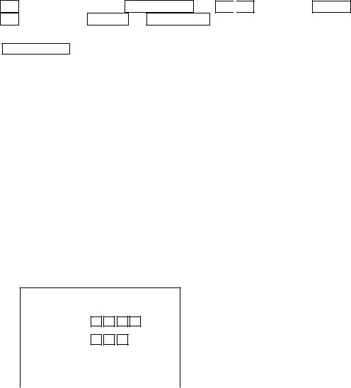
2.2.2 LED Indications
The STATUS LED is green and the ALARM LED is red.
(1) LED indication change at power-on |
□: Turned off ■: Turned on |
|
|
|
|
LED Indication |
|
Description |
|
|
|
BTATUS □□□□ |
The Power is not turned on. |
|
BTATUS ■■■■ |
The CPU is not starting after turning on the power. |
|
BTATUS ■□■■ |
Each processor in the system is waiting for ID. |
|
BTATUS □□■■ |
ID setting for each processor in the system is completed. |
|
BTATUS ■■□■ |
Completion of FANUC BUS initialization |
|
BTATUS □■□■ |
Completion of PMC initialization (1) |
|
BTATUS ■□□■ |
Completion of setting of hardware configuration information for each |
|
|
printed circuit board in the system |
|
BTATUS ■■■□ |
Completion of initial run of the PMC ladder (PMC-RB) |
|
BTATUS □■■□ |
Digital servo initialization wait |
|
BTATUS ■□□□ |
Initial setting is completed and the system is running normally |
|
|
|
|
1 - 11
(2) LED indications for errors
|
|
□: Turned off ■: Turned on ×: Irrelevant |
|
|
|
LED Indication |
Description |
|
|
|
|
STATUS |
□■□□ |
The main CPU board has a RAM parity error or the option-2 board |
ALARM |
■■□ |
has a servo alarm or RAM parity. |
|
|
|
STATUS |
□■□□ |
A servo alarm (watchdog timer alarm) occurred. |
ALARM |
□■■ |
|
|
|
|
STATUS |
□■□□ |
Other system alarm occurred. |
ALARM |
□■□ |
|
|
|
|
STATUS |
■■■■ |
The system is stopping before the CPU is started. |
ALARM |
×■× |
|
|
|
|
2.2.3 Connectors
Symbol |
Name |
Description |
|
|
|
JA1 |
CRT |
CRT video signal |
JA2 |
MDI |
MDI keyboard |
JD5A |
R232-1 |
RS-232C serial port |
JD5B |
R232-2 |
RS-232C serial port |
JA3 |
MPG |
Manual pulse generator |
JD1A |
IOLINK |
FANUC I/O link |
JA7A |
SPDL-1 |
Serial spindle |
JA8A |
A-OUT1 |
Analog output |
JA4A |
APCBAT |
APC battery |
JS1A |
SERV01 |
1st axis servo amplifier |
JS2A |
SERV02 |
2nd axis servo amplifier |
JS3A |
SERV03 |
3rd axis servo amplifier |
JS4A |
SERV04 |
4th axis servo amplifier |
JS5A |
SERV05 |
5th axis servo amplifier |
JS6A |
SERV06 |
6th axis servo amplifier |
JF21 |
SCALE1 |
1st axis scale |
JF22 |
SCALE2 |
2nd axis scale |
JF23 |
SCALE3 |
3rd axis scale |
JF24 |
SCALE4 |
4th axis scale |
JA26 |
SV-CHK |
Servo check |
|
|
|
1 - 12

2.3 Option-1 Board (DNC)
|
|
|
This is a DNC operation board. |
|
|
|
|
|
|
|||||||||||
|
|
|
|
|
|
|
|
|
|
|
|
|
|
|
|
|
|
|
|
|
|
|
|
|
Name |
|
|
|
Specification |
|
|
|
Type |
|
|
||||||
|
|
|
|
|
|
|
|
|
|
|
|
|
|
|
|
|
|
|
|
|
|
|
|
Option-1 Board |
|
Remote Buffer |
|
|
A16B-2200-0913 |
|
|
||||||||||
|
|
|
|
|
|
|
|
|
|
|
|
|
|
|
|
|
|
|
|
|
|
|
|
|
|
|
|
|
|
|
|
|
|
|
|
|
|
|
|
|
|
|
|
|
|
|
|
|
|
|
|
|
|
|
|
|
|
|
|
|
|
|
|
|
|
|
|
|
|
|
CPU |
|
|
|
|
|
|
LED |
|
|
JD5C |
|
|
|
|
|
|
|
|
|
|
|
|
|
|
|
|
|
|
|||||
|
|
|
|
|
|
|
|
|
|
|
|
|
|
|
|
|
|
|
||
|
|
|
|
|
|
|
|
|
|
|
|
|
|
|
|
|
|
|
||
|
|
|
|
|
|
|
|
|
|
|
|
|
|
|
|
|
|
|
||
|
|
|
|
|
|
|
|
|
|
|
|
|
|
|
|
|
|
|
||
|
|
|
|
|
|
|
|
|
|
|
|
|
|
|
|
|
|
|
||
|
|
|
|
|
|
|
|
|
|
|
|
|
|
|
|
|
|
JD6A |
|
|
|
|
|
|
|
|
|
|
|
|
|
|
|
|
|
|
|
|
|
|
|
|
|
|
|
|
|
|
|
|
|
|
|
|
|
|
|
|
|
|
|
|
|
|
|
|
|
|
|
|
|
|
|
|
|
|
|
|
|
|
|
|
|
|
|
|
|
|
|
|
JNA |
Communication ROM |
|
|
|
|
|
|
|
|
||||
|
|
|
|
|
|
|
|
|
|
|
|
|
|
|
||||||
|
|
|
|
|
|
|
|
|
|
|
|
|
|
|||||||
|
|
|
|
|
|
|
|
|
|
|
|
|
|
|
|
|
|
|
||
|
|
|
|
|
|
|
|
|
|
|
|
|
|
|
|
|
|
|
||
|
|
|
|
|
|
|
F-BUS |
|
|
|
|
|
|
|
|
|
|
|
|
|
|
|
|
|
|
|
|
Backplane |
|
|
|
|
|
|
|
|
|
|
|
||
|
|
|
|
|
|
|
Connector |
|
|
|
|
|
|
|
|
|
|
|
||
|
|
|
|
|
|
|
|
|
|
|
|
|
|
|
|
|
||||
|
|
|
|
|
|
|
|
|
|
|
|
|
|
|
|
|
|
|
|
|
2.3.1 |
List of Modules |
|
|
|
|
|
|
|
|
|
|
|
|
|||||||
|
|
|
|
|
|
|
|
|
|
|
|
|
|
|
|
|
||||
|
No. |
|
Name |
|
|
Function |
Specification |
Type |
||||||||||||
|
|
|
|
|
|
|
|
|
|
|
|
|
|
|
|
|
||||
|
|
|
Communication |
Communication control |
|
|
|
A20B-2901-0361 |
||||||||||||
|
|
|
control module |
|
|
|
|
|
|
|
|
|
|
|
|
|||||
|
|
|
|
|
|
|
|
|
|
|
|
|
|
|
|
|
|
|
||
2.3.2 |
LED Indications |
|
|
|
|
|
|
|
|
|
|
|
|
|||||||
|
|
|
|
|
|
|
|
|
|
|
Indicates the status of the communicating function |
|||||||||
|
|
|
STATUS |
□□□□ |
(green) |
|
|
|
|
|
|
|||||||||
|
|
|
ALARM |
□□□ |
|
(red) |
|
|
|
|
|
|
||||||||
|
|
|
Indication of Communicating Function |
|
|
|
|
|
|
|||||||||||
|
|
|
|
|
|
|
□: Turned off ■: Turned on |
×: Irrelevant : Blinking |
|
|
||||||||||
1 - 13
LED Indication |
Description |
|
|
|
|
STATUS |
■■■■ |
The CPU is not running after turning on the power. |
ALARM |
■□□ |
|
|
|
|
STATUS |
××□■ |
The remote buffer has been initialized and the system is running |
ALARM |
□□□ |
normally. |
|
|
|
STATUS |
×× |
There is an error in communication control of the option-1 board. |
ALARM |
□□□ |
|
|
|
|
2.3.3 Connectors
Symbol |
Name |
Description |
|
|
|
JD5C |
R232-3 |
RS-232C serial port |
JD6A |
R422-1 |
RS422 serial port |
|
|
|
2.4 Option-3 Board (PMC)
This is a sequence control board.
Name |
Specification |
Type |
|
|
|
Option-3 board |
PMC-RC |
A16B-3200-0054 |
|
|
|
|
|
LED |
|
|
|
|
|
|
|
||
|
|
|
|
|
JD1A |
|
|
|
|
|
|
|
|
|
|
|
|
|
|
|
|
|
JE5D |
|
|
|
|||
|
|
|
|||
|
|
|
|
|
JE5E |
|
|
|
|
|
|
|
|
|
|
|
|
|
|
|
|
|
JE6B |
|
|
|
|
|
|
|
|
|
|
|
|
|
|
|
|
|
|
|
|
|
|
|
|
JNA
F-BUS
Backplane
Connector
1 - 14
2.4.1 List of Modules
No. |
Name |
Function |
Specification |
Type |
|
|
|
|
|
|
DRAM module |
DRAM for PMC |
|
|
|
for PMC |
|
|
|
|
|
|
|
|
|
PMC control |
PMC control |
PMP2 |
A20B-2901-0960 |
|
module |
|
|
A20B-2901-0961 |
|
|
|
|
|
2.4.2 LED Indications |
|
|
|
||||
Indicates the status of |
|
|
|
|
|
|
Indicates the status of |
|
|
|
|
|
|||
the PMC-RC function |
|
|
|
|
the CAP-II function |
||
|
|
|
|
|
|
|
[Not used] |
|
|
|
|
|
|
|
|
STATUS |
|
(green) |
|||||
ALARM |
|
(red) |
|||||
(1)LED indications for the PMC-RC function
(a)LED indication change at power-on
□: Turned off ■: Turned on ×: Irrelevant
LED Indication |
Description |
|
|
|
|
STATUS |
■■×× |
The CPU is not starting after turning on the power. |
STATUS |
□□×× |
Waiting for ID setting for each processor in the system |
STATUS |
■■×× |
Waiting for completion of initialization of each processor in the |
|
|
system |
STATUS |
□□×× |
Initialization of the PMC-RC function is completed and the system is |
|
|
running normally. |
|
|
|
(b)LED indications for errors
□: Turned off ■: Turned on ×: Irrelevant : Blinking
LED Indication |
Description |
|
|
|
|
STATUS |
×× |
Other printed circuit board has NMI. (LEDs blinking simultaneously) |
Check other printed circuit board for LED indication. |
||
ALARM |
□□□ |
Parity error for the ladder memory or work memory. |
|
|
|
|
|
|
STATUS |
□ ×× |
Initialize the ladder memory or replace the work RAM module. |
ALARM |
■□□ |
A bus error (illegal memory access) occurred. |
|
|
|
STATUS |
□×× |
Replace the option-3 board. |
ALARM |
□□□ |
|
|
|
|
1 - 15

LED Indication |
Description |
|
|
|
|
STATUS |
■ ×× |
An I/O link has a communication error, etc. |
ALARM |
□□□ |
Check a link device or cable. |
|
|
|
STATUS |
■×× |
The PMC control module has a parity error, etc. in it. |
ALARM |
■□□ |
Replace the PMC control module. |
|
|
|
STATUS |
×× |
Checksum error for the system program memory. |
ALARM |
□□□ |
The DRAM module for PMC may be defective. |
|
|
|
2.4.3 Connectors |
|
|
|
|
|
|
|
|
|
|
Symbol |
Name |
Description |
|
|
|
|
|
|
|
JD1A |
IOLINK |
FANUC I/O LINK |
|
|
|
|
|
|
|
JD5D |
RS232-4 |
RS232C |
|
|
|
|
|
May not be installed |
|
JD5E |
RS232-5 |
Unused |
|
|
|
|
|
|
|
JD6B |
R422-2 |
Unused |
|
|
|
|
|
|
2.5 64-bit RISC Board (RISC) ...... |
for M |
This is a board designed for high-accuracy profile control.
Name |
Type |
|
|
64bit RISC board |
A16B-3200-0150 |
|
|
2.5.1 LED Indications
The STATUS LED is green and ALARM LED is red.
(1) LED indication change at power-on |
□: Turned off ■: Turned on |
||
|
|
|
|
LED Indication |
|
Description |
|
|
|
||
STATUS □□□□ |
The power is not turned on. |
||
STATUS |
■■■■ |
The RISC CPU is not starting after turning on the power. |
|
STATUS □□□■ |
The DRAM and SRAM are being tested. (When an error is detected |
||
|
|
during a test, this in-test LED indication is held) |
|
STATUS |
□□■□ |
The ROM is being tested. (When an error is detected during a test, |
|
|
|
this in-test LED indication is held) |
|
STATUS |
■□□□ |
Waiting for a request from the main CPU request (1) |
|
STATUS |
■□□■ |
Waiting for a request from the main CPU request (2) |
|
STATUS |
■□■□ |
Waiting for a request from the main CPU request (3) |
|
STATUS |
■■□□ |
Waiting for a request from the main CPU request (4) |
|
|
|
|
|
1 - 16
(2) LED indication while running |
□: Turned off |
■: Turned on |
|
|
|
|
|
LED Indication |
|
Description |
|
|
|
|
|
STATUS □□□ |
Waiting for the RISC mode |
|
|
STATUS □ □ |
Waiting for an input of NC statement |
|
|
STATUS □ □ |
Running a command in the RISC mode |
|
|
STATUS □□□ |
Resetting |
|
|
STATUS □ |
Override 0 at acceleration/deceleration time before inter-polation |
||
|
(Waiting for an override change) |
|
|
|
|
|
|
(3) LED indication for errors |
□: Turned off |
■: Turned on |
|
|
|
|
|
LED Indication |
|
Description |
|
|
|
||
STATUS □□□■ |
An error was detected in testing the DRAM or SRAM on the RISC |
||
|
board. |
|
|
STATUS □□■□ |
An error was detected in testing the ROM module. |
||
STATUS □□■■ |
A synchronizing signal from the main CPU cannot be detected. |
||
STATUS □■□□ |
An error was detected in accessing the F-BUS. |
|
|
STATUS ■■■□ |
System error |
|
|
|
|
|
|
(4) ALARM LED indications |
□: Turned off |
■: Turned on |
|
|
|
|
|
LED Indication |
|
Description |
|
|
|
|
|
STATUS ■□□ |
The RISC CPU is not starting. |
|
|
STATUS □■□ |
SRAM parity |
|
|
STATUS □□■ |
DRAM parity |
|
|
|
|
|
|
2.6 MMC-IV BOARD (MMC-IV) ...... Applies only to Multi-Interactive Spec.
This DOS-V personal computer is used in multi-interactive processing. This is a board designed for high-accuracy profile control.
Name |
MODEL |
A02B-0207-C022 (Conventional type)
MMC-IV BOARD
A16B-2203-0180 (New type)
Note) The conventional and new types of MMC-IV Board are differentiated by use of a memory card socket.
•Conventional type: With a memory card socket
•New type: Without a memory card socket
2.6.1SETTING ADJUSTMENT
Since Machine is delivered as having been adjusted prior to shipment, no change is necessary under normal circumustances.
1 - 17
2.6.2 LED DISPLAY |
|
|
|
||
|
STATUS LED in green color and ALARM LED in red color. |
|
|||
|
(1) Normal state |
□: Turned off |
■: Turned on |
×: Irrelevant |
|
|
|
|
|
|
|
|
LED Indication |
|
Description |
|
|
|
|
|
|
|
|
|
STATUS □□□□ |
|
Power OFF state |
|
|
|
STATUS ■××× |
|
MMC-IV reset cancelled |
|
|
|
STATUS ×××■ |
|
HDD access lamp |
|
|
|
|
|
|
|
|
|
(2) Abnormal state |
■: Turned on |
×: Irrelevant |
||
|
|
|
|
||
|
LED Indication |
|
Description |
|
|
|
|
|
|
|
|
|
STATUS ■×× |
|
NMI has occurred in MMC-IV CPU. |
|
|
|
STATUS ×■× |
|
Ambient temperature of HDD is either equal to or below 5°C or |
||
|
|
|
equal to or above 55°C. |
|
|
|
STATUS ××■ |
|
Parity alarm has occurred in DRAM on the back plane. |
||
|
|
|
|
|
|
2.7 LIQUID CRYSTAL DISPLAY (LCD)
This is a board designed for high-accuracy profile control.
Name |
SPEC. |
MODEL |
|
|
|
9.5" Monochromatic LCD |
Without Multi |
A02B-0222-C110 |
|
|
|
10.4" Color LCD |
Without Multi |
A02B-0222-0150 |
|
|
|
10.4" Color LCD |
With Multi |
A02B-0200-0153 |
|
|
|
2.7.1ADJUSTMENT REQUIRED
(1)For A02B-0222-C110 ...... Without Multi Spec./9.5" Monochromatic LCD
VRD 1
DISPLAY, REAR VIEW
1 - 18
•VRD1 (Contrast Adjustment)
Through adjustment of VRD1, contrast can be adjusted.
Note
Do not change any setting, volume, etc. other than those mentioned above. A change, if made in any setting other than the above, results in incorrect screen display.
(2)For A02B-0222-C150 ...... Without Multi Spec./10.4" Color LCD
This display does not include the set pin, volume, etc. for screen adjustment.
Note
Do not change any setting, volume, etc. other than those mentioned above. A change, if made in any setting other than the above, results in incorrect screen display.
(3) For A02B-0200-C153 ...... With Multi Spec./10.4" Color LCD
T M 1
• • •
SW 1
DISPLAY, REAR VIEW
•TM1 (Flicker Adjustment)
On occurrence of flicker on the screen, change setting of the set pin TM1 into the other. Normally, flicker can be eliminated in one of these two ways.
•SW1 (Setting of Horizontal Position)
Use this to shift a display screen horizontally by one dot.
Use this to set position where all displays are available. There is only one place for toral display. As it is normally set prior to shipment, no change is necessary.
Note
Do not change any setting, volume, etc. other than those mentioned above. A change, if made in any setting other than the above, results in incorrect screen display.
1 - 19
2.8 DATA SERVER BOARD
|
|
|
|
Name |
|
|
|
MODEL |
|
|
|
|
|
|
|
|
|
||
|
|
|
DATA SERVER BOARD |
|
|
A16B-2202-0630 |
|
||
|
|
|
|
|
|
|
|
|
|
2.8.1 LED DISPLAY |
|
|
|
|
|
|
|||
|
|
|
STATUS LED in green color and ALARM LED in red color. |
||||||
|
|
|
(1) LED Indications on Supply of Power |
□: Turned off ■: Turned on |
|||||
|
|
|
|
|
|
|
|
||
|
No |
LED |
1 2 3 4 |
|
|
|
DATA SERVER STATE |
||
|
|
|
display |
|
|
|
|
|
|
|
|
|
|
|
|
|
|||
|
1 |
STATUS □□□□ |
Power OFF state |
|
|
|
|||
|
|
|
|
|
|||||
|
2 |
STATUS |
■■■■ |
Initial state immediately after supply of power. |
|||||
|
|
|
|
|
|
|
|||
|
3 |
STATUS |
□■■■ |
|
|
Main memory test |
|||
|
|
|
|
|
|
|
|||
|
4 |
STATUS |
■□■■ |
|
|
Ethernet RAM test |
|||
|
|
|
|
|
|
|
|||
|
5 |
STATUS |
□□■■ |
|
|
Common RAM test |
|||
|
|
|
|
|
|
||||
|
6 |
STATUS |
■■□■ |
Hardware in |
Initialization of system area |
||||
|
7 |
STATUS |
□■□■ |
checking |
FANUC BUS interrupt test 1 |
||||
|
|
|
|
|
|
|
|||
|
8 |
STATUS |
■□□■ |
|
|
FANUC BUS interrupt test 2 |
|||
|
|
|
|
|
|
|
|||
|
9 |
STATUS |
□□□■ |
|
|
FANUC BUS interrupt test 3 |
|||
|
|
|
|
|
|
|
|||
|
10 |
STATUS |
■■■□ |
|
|
FANUC BUS interrupt test 4 |
|||
|
|
|
|
|
|
|
|||
|
11 |
STATUS |
□■■□ |
|
|
Initialization of interrupt controller |
|||
|
|
|
|
|
|
||||
|
12 |
STATUS |
■□■□ |
Starting of |
Initialization BIOS |
||||
|
|
|
|
|
data serve |
|
|
|
|
|
13 |
STATUS |
□□■□ |
Program loading |
|||||
|
software |
||||||||
|
14 |
STATUS |
■□□□ |
Completion of starting of the data server board |
|||||
|
|
|
|
|
|
|
|
|
|
When the data server board starts properly, LED display is stopped in “No.14” state.
1 - 20
(2)LED Indications on Occurrence of Error (STATUS)
□: Turned off ■: Turned on ×: Irrelevant
“STATUS” LED repeats “LONG” and “SHORT” patterns. The “LONG” pattern is displayed for a longer time length, while the “SHORT” one for a shorter time length.
No |
LED DISPLAY (STATUS) |
DATA SERVER STATE |
||
|
|
|||
LONG |
SHORT |
|||
|
|
|||
|
1 2 3 4 |
1 2 3 4 |
|
|
1 |
□□□■ |
□□■□ |
Main memory failure. Check the data server board. |
|
|
|
|
|
|
2 |
□□□■ |
■□■□ |
Ethernet RAM failure. Check the data server board. |
|
|
|
|
|
|
3 |
□□□■ |
□■■□ |
Common RAM failure. Check the data server board. |
|
|
|
|
|
|
4 |
■□□■ |
×××× |
An invalid interrupt has been given to CPU. |
|
|
|
|
|
|
5 |
□■□■ |
×××× |
An invalid interrupt has been given to CPU. |
|
|
|
|
|
|
6 |
■■□■ |
×××× |
An invalid interrupt has been given to CPU. |
|
|
|
|
|
|
7 |
□■■■ |
■□□□ |
A system error has occurred in the data server board. |
|
|
|
|
|
|
8 |
□□■■ |
■□□□ |
A bus error has occurred in FUNUC BUS. Check the data |
|
|
|
|
server board. |
|
|
|
|
|
|
9 |
□□■■ |
□■□□ |
A parity error has occurred in the main memory. |
|
|
|
|
|
|
10 |
□□■■ |
■■□□ |
A parity error has occurred in the Ethernet RAM. |
|
|
|
|
|
|
11 |
□□■■ |
□□■□ |
A parity error has occurred in the Common RAM. |
|
|
|
|
|
|
12 |
□□■■ |
■□■□ |
“Refresh” to the main memory has ceased for a time longer |
|
|
|
|
than the set length. |
|
|
|
|
|
|
|
(3) LED Display on Occurrence of Error (ALARM) |
|||
|
|
|
■: Turned on ×: Irrelevant |
|
|
|
|
||
No |
LED DISPLAY 1 2 3 |
DATA SERVER STATE |
||
|
|
|
|
|
1 |
ALARM |
■×× |
Either a parity error has occurred in any of the main memory, |
|
|
|
|
Ethernet RAM, and Common RAM, or “refresh” to the main |
|
|
|
|
memory has ceased for a time longer than the set length. |
|
|
|
|
Referring to “STATUS” LED NO’s 9 to 12, identify the failure |
|
|
|
|
and replace the part. |
|
|
|
|
|
|
2 |
ALARM |
×■× |
Fuse is gone. Replace a fuse. |
|
|
|
|
|
|
3 |
ALARM |
××■ |
CPU is in Halt or SHUTDOWN state. |
|
|
|
|
Check the board. |
|
|
|
|
|
|
1 - 21

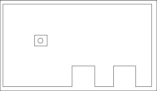
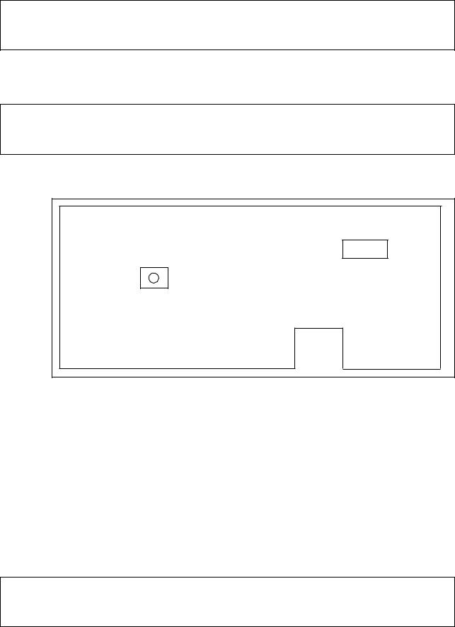
2.8.2REPLACEMENT OF FUSE
(1)Check the fuse on the front panel of the data server board for any disconnection. On occurrence of disconnection, a white marker appears in a small window of the fuse.
(2)Remove the cause which has disconnected the fuse.
(3)Pulling out the disconnected fuse, insert a new one of the same specification.
|
|
|
|
|
|
|
|
|
|
|
|
|
|
|
|
STATUS |
|
|
Fuse |
||||
ALARM |
|
||||||
|
|
||||||
F 1 |
|
|
|
|
Fuse specification: A08B-0048-K101 |
||
|
|
|
Capacity:2.0A |
||||
2.0A |
|
|
|
Application: For Ethernet supply power |
|||
|
|
|
|
|
|
|
|
|
|
|
|
|
|
|
|
1 - 22
2.9 LIST OF UNITS AND PRINT BOARDS
2.9.1 CONTROL UNIT RACK
|
NAME |
|
SPECIFICATIONS |
TYPE |
|
|
|||||
|
|
|
|
|
|
|
|
|
|
|
|
|
S-Σ 10L |
|
MMC-IV not |
6 slots |
A02B-0200-C003 |
|
|
||||
|
|
provided |
|
8 slots |
A02B-0200-C004 |
|
|
||||
|
CONTROL UNIT |
|
|
|
|
||||||
|
|
|
|
|
|
|
|
|
|
|
|
|
|
MMC-IV |
|
6 slots |
A02B-0200-C011 |
|
|
||||
|
RACK |
|
|
|
|
||||||
|
provided |
|
8 slots |
A02B-0200-C012 |
|
|
|||||
|
|
|
|
|
|
||||||
|
|
|
|
|
|
|
|
|
|
|
|
|
S-Σ 10L |
|
MMC-IV not |
4 slots |
A02B-0129-C002 |
|
|
||||
|
|
provided |
|
6 slots |
A02B-0129-C003 |
|
|
||||
|
CONTROL UNIT |
|
|
|
|
||||||
|
|
|
|
|
|
|
|
|
|
|
|
|
|
MMC-IV |
|
4-slots |
A02B-0129-C010 |
|
|
||||
|
RACK |
|
|
|
|
||||||
|
|
provided |
|
6 slots |
A02B-0129-C011 |
|
|
||||
|
|
|
|
|
|
||||||
|
|
|
|
|
|
|
|
|
|
|
|
2.9.2 POWER UNIT |
|
|
|
|
|
|
|
|
|
||
|
|
|
|
|
|
|
|
|
|
||
|
NAME |
|
|
|
|
TYPE |
|
|
|||
|
|
|
|
|
|
|
|
|
|
||
|
POWER UNIT AI |
|
|
|
|
A16B-1212-0901 |
|
|
|||
|
|
|
|
|
|
|
|
|
|
||
|
POWER UNIT BI |
|
|
|
|
A16B-1212-0871 |
|
|
|||
|
|
|
|
|
|
|
|
|
|
|
|
2.9.3 CONTROL UNIT P.C.B. |
|
|
|
|
|
|
|
|
|
||
|
|
|
|
|
|
|
|
||||
|
NAME |
|
SPECIFICATIONS |
|
TYPE |
|
|
||||
|
|
|
|
|
|
|
|
|
|
|
|
|
MAIN CPU BOARD |
|
S-Σ |
10M |
|
|
|
A16B-3200-0190 |
|
|
|
|
|
|
|
|
|
|
|
|
|
||
|
|
S-Σ |
10L |
|
|
|
A16B-3200-0210 |
|
|
||
|
|
|
|
|
|
|
|
|
|||
|
|
|
|
|
|
|
|
||||
|
OPTION 1 BOARD |
|
REMOTE BUFFER |
|
A16B-2200-0913 |
|
|
||||
|
|
|
|
|
|
|
|
|
|
||
|
OPTION 3 BOARD |
|
PMC-RC |
|
|
|
A16B-3200-0054 |
|
|
||
|
|
|
|
|
|
|
|
|
|
|
|
|
HIGH-SPEED SKIP |
|
|
|
|
|
|
A16B-2200-0954 |
|
|
|
|
SIGNAL INPUT BOARD |
|
|
|
|
|
|
|
|||
|
|
|
|
|
|
|
|
|
|||
|
|
|
|
|
|
|
|
|
|
|
|
|
CONTROL UNIT |
|
|
|
|
|
|
A20B-8001-0480 |
|
|
|
|
GRAPHIC BOARD |
|
|
|
|
|
|
|
|
||
|
|
|
|
|
|
|
|
|
|
||
|
|
|
|
|
|
|
|
|
|
|
|
|
64-BIT RISC BOARD |
|
|
|
|
|
|
A16B-3200-0150 |
|
|
|
|
|
|
|
|
|
|
|
|
|
||
|
DATA SERVER BOARD |
|
|
|
|
|
A16B-2202-0630 |
|
|
||
|
|
|
|
|
|
|
|
|
|
|
|
|
|
|
|
|
|
|
|
|
A02B-0207-C022 |
|
|
|
MC-IV BOARD |
|
MULTI- |
|
|
|
(Conventional type) |
|
|
||
|
|
INTERACTIVE |
|
|
|
|
|||||
|
|
|
A16B-2203-0180 |
|
|
||||||
|
|
|
|
|
|
|
|||||
|
|
|
|
|
|
|
|
|
|
|
|
|
|
|
|
|
|
|
|
|
(New type) |
|
|
|
|
|
|
|
|
|
|
|
|
|
|
1 - 23
3. TROUBLESHOOTING
When a trouble happened, check “when it happened,” “what you were operating,” “what it was like,” and “how often it happens.”
3.1 Tracking through the ALARM Screen
When an alarm happened during operation, an alarm message appears on the top area of the screen.
For some alarms, the details are displayed on the diagnostic screen. Confirm, then, the description on the diagnostic screen in the following operation:
[Display Operation of Diagnostic Screen]
While NC “General Screen” is displayed, operate as:
2
(OPER./MAINTE) → F4 SYSTEM → 3 
 0 (F MENU) INPUT → (F_SYSTEM) INPUT → F7 DGNOS
to display the diagnostic screen. Input, then, a number to be referred to and push F6 NO.SRH . Data for the diagnostic number are displayed. (The page key is
useable to make a change.)
(Note 1)
(Note 2)
When the diagnostic function does not appear in F7 following “F SYSTEM” being selected in the above operation, push (RETURN) a few times.
Use |
ALTER |
, not |
|
(RETURN), for return operation from the |
diagnostic screen. |
|
|
||
3.2 Tracking through the Controller’s Monitor LEDs
Each unit in the controller has monitor LEDs so that you can check for the status of each unit. For details, see 2. FUNCTIONS AND HANDLING OF CONTROL UNITS.
Each Unit
STATUS
ALARM
1 - 24

4. POWER-ON ADJUSTMENT
4.1Power-on Procedure
Enter (set) the PMC ladder and others.
Enter (set) the NC parameters.
Turn off the power and turn it on again.
(Note) When system software has not been entered into the NC internal memory, transfer it into the NC internal memory according to the instructions in [APPENDIX] BOOT SYSTEM, and then, go through the above-mentioned steps.
4.2System Table
This CNC unit sets allocations of the data areas such as machining program, tool offset amount through the "system table."
To display the System Table screen, operate in the following order in the Overall screen:


OPER./MAINTE → F4/SYSTEM → 2 
 5 (SYSTEM TABLE) → INPUT
|
SYSTEM TABLE |
|
|
|
|
|
|
|
|
|
|
|
|
||
|
|
|
|
|
|
|
|
|
|
|
|
|
|||
|
BASIC RAM SIZE |
38E40 |
|
|
|
|
EXT. RAM SIZE |
|
0 |
|
|
||||
|
|
|
|
|
|
|
|
|
|
|
|
|
|
|
|
|
|
No. |
TABLE |
SIZE |
OFFSET |
|
No. |
TABLE |
|
SIZE |
OFFSET |
|
|||
|
|
01 |
SYSTEM |
10000 |
0 |
|
|
11 |
|
|
0 |
0 |
|
||
|
|
02 |
TOOL |
5000 |
0 |
|
|
12 |
|
|
0 |
0 |
|
||
|
|
03 |
SPARE |
3900 |
0 |
|
|
13 |
|
|
0 |
0 |
|
||
|
|
04 |
MONI |
6F00 |
0 |
|
|
14 |
|
|
0 |
0 |
|
||
|
|
05 |
PRGRM |
13000 |
0 |
|
|
15 |
DUMMY |
|
6600 |
32800 |
|
||
|
|
|
|
|
|
|
|
|
|
|
|
|
|
|
|
|
|
06 |
|
0 |
0 |
|
|
16 |
|
|
0 |
0 |
|
||
|
|
07 |
|
0 |
0 |
|
|
17 |
|
|
0 |
0 |
|
||
|
|
08 |
|
0 |
0 |
|
|
18 |
|
|
0 |
0 |
|
||
|
|
09 |
|
0 |
0 |
|
|
19 |
|
|
0 |
0 |
|
||
|
|
10 |
|
0 |
0 |
|
|
20 |
|
|
0 |
0 |
|
||
|
|
|
|
|
|
|
|
|
|
|
|
|
|
|
|
|
|
|
|
|
|
|
|
|
|
|
|
|
|
|
|
When initially starting up the system, press |
|
to initialize the system. |
|||||||||||||
F5/SYSTEM CLR |
|||||||||||||||
When this is done, the basic RAM capacity and extended RAM capacity are automaticlly set. Pressing F3/TABLE brings the cursor into the table. In accordance with the names versus capacities table provided on the next page, set the table names and capacities, using [Cursor] and [Alphanumeral] plus the INPUT key.
1 - 25
(Note 1) The numbers 01 through 15 are the tables for the basic RAM, and 16 through 20 are those for the extended RAM. When the extended RAM capacity is 0 (zero), do not set for the numbers 16 through 20.
(Note 2) Set the capacity in an increment of 100, suffixing a numeral with “H” (indicates hexadecimal)
(Note 3) If the capacity is entered, the offset for the next table will be automatically set. Different from the S-III, however, the last table capacity is not adjusted. Set a dummy table before the last table capacity so that it will be of specified capacity.
(Note 4) The table number 01 has a fixed table name, “SYSTEM,” and capacity, “1000H.” For the other tables, you can set any table names in any places.
(Note 5) A standard set value varies from one model to another. When actually setting it, follow the materials for each model.
(Note 6) When the system table is changed, be sure to turn off and on the power to make sure that “790 System Table Error” does not occur, and then, start
1 - 26
 Loading...