

Page 1

SEIKI - SEICOS
å10/ 16/18/ 21
INSTRUCTION MANUAL
MAINTENANCE
41 Edition 1.01 11-2000
Hitachi Seiki Deutschland
Werkzeugmaschinen GmbH
Page 2

Page 3

CONTENTS
I-I SEICOS
1. OVERVIEW .........................................................................................................................1 - 3
2. FUNCTIONS AND HANDLING OF CONTROL UNITS......................................................... 1 - 7
3. TROUBLESHOOTING ...................................................................................................... 1 - 24
4. POWER-ON ADJUSTMENT ............................................................................................. 1 - 25
5. DAIL Y MAINTENANCE AND INSPECTION ........................................................................ 1 - 29
I-II SEICOS
1. OVERVIEW ....................................................................................................................... 1 - 33
2. PCB CONNECTORS AND CARD CONFIGURATION ...................................................... 1 - 37
3. TROUBLESHOOTING ...................................................................................................... 1 - 50
4. POWER-ON ADJUSTMENT ............................................................................................. 1 - 51
5. DAIL Y MAINTENANCE AND INSPECTION ........................................................................ 1 - 55
ΣΣ
Σ 10 UNIT ............................................................................. 1 - 2
ΣΣ
ΣΣ
Σ 16/18/21 UNIT................................................................ 1 - 32
ΣΣ
I-III RS-232C INTERFACE SPECIFICATION ....................................... 1 - 62
II. ALARM LIST ....................................................................................... 2 - 1
1. Alarms Related to Program and Operation..........................................................................2 - 2
2. Alarms Related to Absolute Pulse Coder (APC) ................................................................ 2 - 50
3. Alarms Related to Serial Pulse Coder (SPC) ....................................................................2 - 52
4. Alarms Related to Servo....................................................................................................2 - 56
5. Alarms Related to Overtravel............................................................................................. 2 - 67
6. Alarms Related to Overheat...............................................................................................2 - 69
7. Alarms Related to Direct Tap ............................................................................................. 2 - 70
8. Alarms Related to Serial Spindle........................................................................................ 2 - 71
9. System Alarms ..................................................................................................................2 - 73
III. PARAMETERS ................................................................................... 3 - 1
1. DISPLA Y, SETTING, AND OUTPUT OF PARAMETERS...................................................... 3 - 2
2. DESCRIPTION OF P ARAMETERS..................................................................................... 3 - 5
2.1 Parameters Related to Communication (RS-232C) (No. 0100 onward)...................... 3 - 8
2.2 Parameters Related to Axis Control/Input Increment ................................................. 3 - 17
2.3 Parameters Related to Coordinate System ............................................................... 3 - 26
2.4 Parameters Related to Stroke Limit ........................................................................... 3 - 33
2.5 Parameters Related to Chuck Tail Stock Barrier (L-system) ..................................... 3 - 37
2.6 Parameters Related to Feed Rate ............................................................................. 3 - 41
2.7 Parameters Related to Acceleration/Deceleration Control......................................... 3 - 49
2.8 Parameters Related to Servo..................................................................................... 3 - 68
2.9 Parameters Related to DI/DO.................................................................................... 3 - 91
2.10 Parameters Related to CRT/MDI, Display, and Editing ............................................ 3 - 96
i
Page 4

2.11 Parameters Related to Program ............................................................................ 3 - 105
2.12 Parameters Related to Pitch Error Compensation ................................................ 3 - 121
2.13 Parameters Related to Spindle Control.................................................................. 3 - 125
2.14 Parameters Related to Tool Offset......................................................................... 3 - 164
2.15 Parameters Related to Canned Cycle ................................................................... 3 - 172
2.16 Parameters Related to Direct Tap.......................................................................... 3 - 191
2.17 Parameters Related to Custom Macro .................................................................. 3 - 201
2.18 Parameters Related to Skip Function .................................................................... 3 - 209
2.19 Parameters Related to Measurement .................................................................... 3 - 212
2.20 Parameters Related to Graphic Display................................................................. 3 - 226
2.21 Parameters Related to Manual Handle Feed, Manual Handle Interrupt,
and Tool Axis Direction Handle Feed...................................................................... 3 - 232
2.22 Parameters Related to Polygon Machining (L-system Only) ................................. 3 - 235
2.23 Parameters Related to Cutting Monitoring ............................................................. 3 - 239
2.24 Parameters Related to High-speed, High-accuracy Contour Control by RISC ...... 3 - 248
2.25 Other Parameters .................................................................................................. 3 - 255
2.26 Parameters Related to Maintenance...................................................................... 3 - 277
IV. DIAGNOSE4 - 1
1. DIAGNOSE DISPLA Y ..........................................................................................................4 - 2
1.1 Input/Output Signals..................................................................................................... 4 - 3
APPENDIX: BOOT SYSTEM ................................................................. A - 1
1. OVERVIEW ......................................................................................................................... A - 2
1.1 St arting up the BOOT SYSTEM................................................................................... A - 3
1.2 System Files and User Files ........................................................................................ A - 3
2. SCREEN CONFIGURA TION AND OPERATING METHODS ..............................................A - 4
2.1 SYSTEM DA TA LOADING Screen................................................................................ A - 5
2.2 SYSTEM DATA CHECK Screen...................................................................................A - 7
2.3 SYSTEM DATA DELETE Screen................................................................................. A - 8
2.4 SYSTEM DATA SAVE Screen ...................................................................................... A - 9
2.5 SRAM DA TA BACKUP Screen................................................................................... A - 11
2.6 MEMORY CARD FILE DELETE Screen.................................................................... A - 14
2.7 MEMORY CARD FORMAT Function ......................................................................... A - 14
2.8 LOAD BASIC SYSTEM .............................................................................................. A - 1 5
3. ERROR MESSAGES AND REMEDIES ............................................................................ A - 17
ii
Page 5

MAINTENANCE
I-I SEICOS Σ 10 UNIT
I-II SEICOS Σ 16/18/21 UNIT
I-III RS-232C INTERFACE SPECIFICATION
II. ALARMS LIST
III. PARAMETERS
IV. DIAGNOSE
1 - 1
Page 6

I-I SEICOS
1. OVERVIEW
1.1 System Configuration
1.2 Component Units List
2. FUNCTIONS AND HANDLING OF CONTROLLER
2.1 Power Unit
2.2 CPU Board
2.3 Option-1 Board (DNC)
2.4 Option-3 Board (PMC)
2.5 64-bit RISC Board (RISC)
2.6 MMC-IV Board (MMC-TV)
2.7 Liquid Crystal Display (LCD)
2.8 Data Server Board
2.9 List of Units and Print Boards
ΣΣ
Σ 10 UNIT
ΣΣ
3. TROUBLESHOOTING
3.1 Tracking through the ALARM Screen
3.2 Tracking through the Controller’s Monitor
4. POWER-ON ADJUSTMENT
4.1 Power-on Procedure
4.2 System Table
4.3 SLBUS Table
5. DAIL Y MAINTENANCE AND INSPECTION
5.1 Replacing the Battery
1 - 2
Page 7
1. OVERVIEW
The SEICOS Σ 10 CNC unit is a compact high-reliability unit provided with up-to-date
device technologies. In the M-system, it enables high-speed, high-accuracy machining by
using 64-bit RISC.
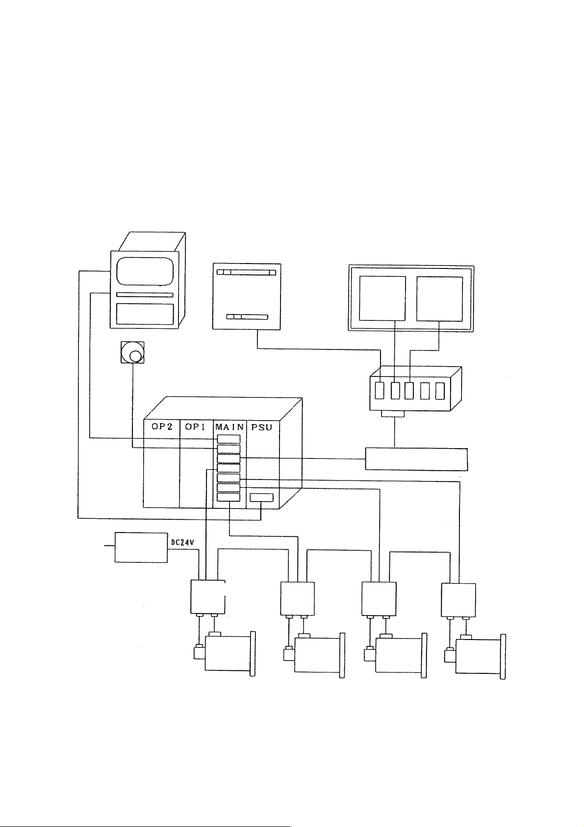
1.1 System Configuration
The following figure shows a system example using the SEICOS Σ 10 CNC unit.
CRT NC Operation Panel
Machine Operation Panel
Manual Pulse Generator
CNC Unit
I/O Slave
SLBUS
Distribution
Board
SLBUS Conversation
Module
200 V AC
Power
Unit
Spindle
Motor
Spindle
Amp.
Servo
Amp.
1 - 3
Servo
Motor
Servo
Amp.
Servo
Motor
Servo
Amp.
Servo
Motor
Page 8
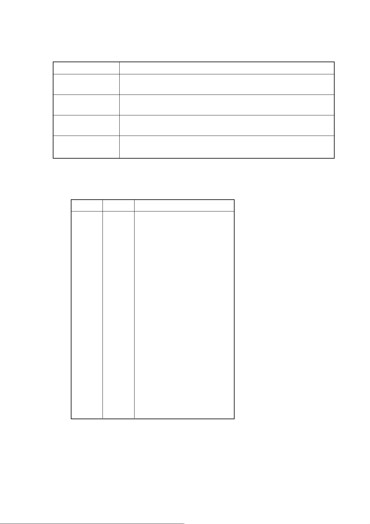
1.2 Component Units List
The following table lists the component units of the controller. A mounting position of
each unit is fixed as shown in the mounting drawing. All the component units are plug-in
type and can be easily replaced.
(1) Unit list
Name Symbol Function/Usage
Power unit PSU ON/OFF control
CPU board MAIN Main CPU
PMC board PMC Sequence control
I/O board I/O High-speed skip
RISC board RISC High-accuracy profile control (for M)
DNC board DNC DNC operation
(Note) The PMC board may be called an “option-3 board,” and DNC board an “option-
1 board,” respectively.
1 - 4
Page 9
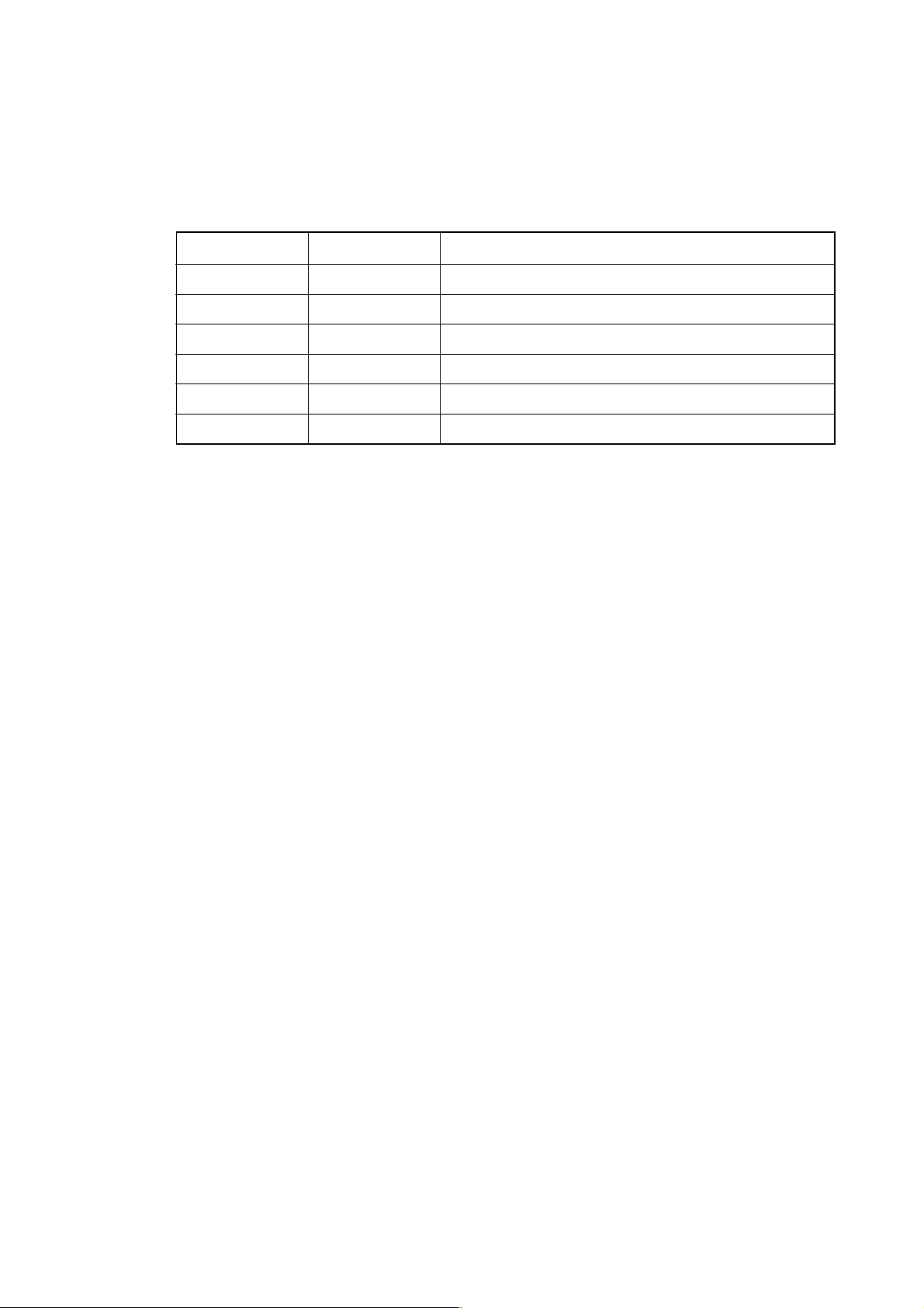
(2) SEICOS Σ 10 unit configuration
DMC
Board
Communication CPU
Remote
Buffer
DNC1
DNC2
Optional
RISC
Board
RISC
CPU
Highaccuracy
Profile
Control
(for M)
I/O
Board
HighSpeed
Skip
PMC
Board
PMC
CPU
PMC-RC3/4
I/O LINK
(Note)
Basic System
CPU
Board
CNC
CPU
Servo 6
Axes,
Spindle
Interface,
CRT,
Keyboard,
RS-232C*2
Memory
Card,
Manual
Handle
PMC-RB5/6
I/O LINK
Power
Unit
ON/OFF
Control
I/O PMC
<
< >
< >
< >
CPU
(Note)
Main
CPU
Power
Source
>
3 Slots
4 Slots
6 Slots
8 Slots
(Note) The PMC board is required when using the “PMC-RC3 or PMC-RC4,” but not
required when using the “PMC-RB5 or PMC-RB6.” [The PMC function is
incorporated in the main CPU board.]
1 - 5
Page 10

(3) SEICOS Σ 10 Multi unit configuration
MMC
Board
MMC-IV
CPU
HDD
FDD
PRT
Keyboard
RS232C
Basic
DMC
Board
Communi-
cation CPU
Remote
Buffer
DNC1
DNC2
(for M)
Highaccuracy
Profile
Control
Optional
RISC
Board
RISC
CPU
I/O
Board
Highspeed
Skip
PMC
Board
PMC
CPU
PMC-RC3/4
I/O LINK
(Note)
Basic System
CPU
Board
CNC
CPU
Servo 6
Axes,
Spindle
Interface,
CRT,
Keyboard,
RS-232C*2,
Memory
Card,
Manual
Handle
PMC-RB5/6
I/O LINK
Gra-
phic
Board
Power
Unit
ON/OFF
Control
I/O PMC
CPU
Main
CPU
Power
Source
(’•)
< >
< >
< >
4 Slots
6 Slots
8 Slots
(Note) The PMC board is required when using the “PMC-RC3 or PMC-RC4,” but not
required when using the “PMC-RB5 or PMC-RB6.” [The PMC function is
incorporated in the main CPU board.]
1 - 6
Page 11
2. FUNCTIONS AND HANDLING OF CONTROL UNITS
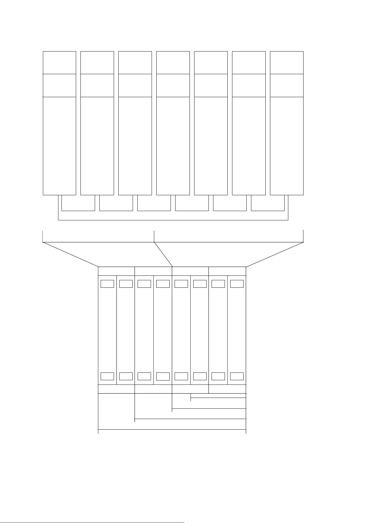
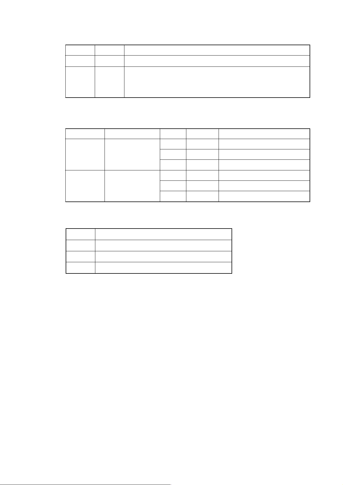
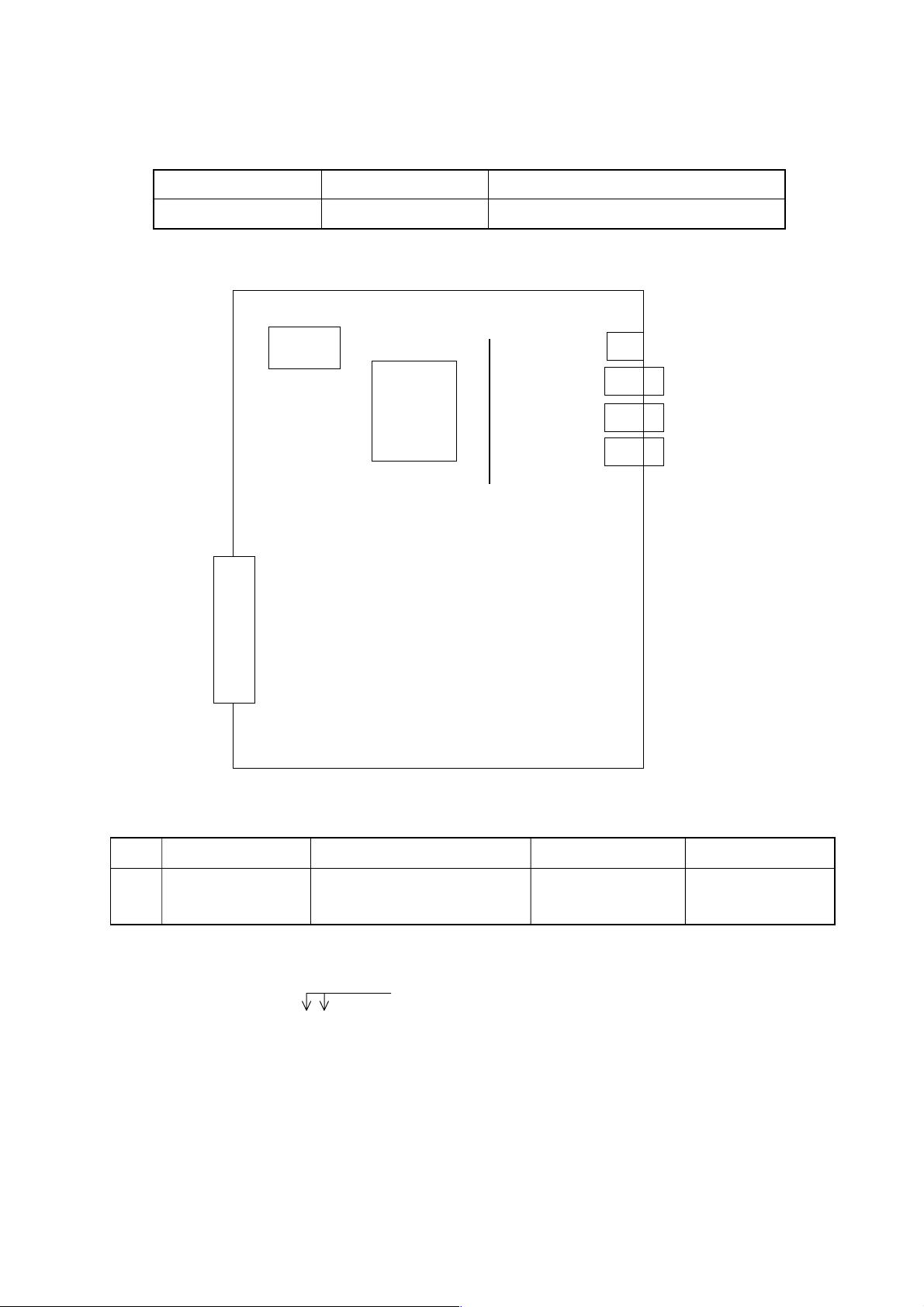
2.1 Power Unit (PSU)
This unit supplies DC power to each control unit.
Name Type
Power Unit AI A16B-1212-0901
Power Unit BI A16B-1212-0871
CP1
(ACIN)
F1
CP2
(ACOUT)
Battery Case
PIL LED
ALM LED
Graphic Board [MULTI Specification Only]
CP5
(24V)
CP3
(ACOUT)
CP4
CONTROL
CP6
(24E)
F3
F4
1 - 7
Page 12
2.1.1 LED Indications
Signal Color Description
PIL Green Illuminated when an input supply voltage is supplied to the CP1.
ALM Red Illuminated when a DC output voltage has an overcurrent/
2.1.2 FUSE
(1) Type
Power Unit Order No. Symbol Ratings Individual No.
AI A02B-0200-K100 F3 3.2A A60L-0001-0075#3.2
BI A02B-0200-K101 F3 5.0A A60L-0001-0075#5.0
overvoltage or drops.
F1 7.5A A60L-0001-0245#GP75
F4 5.0A A60L-0001-0046#5.0
F1 7.5A A60L-0001-0245#GP75
F4 5.0A A60L-0001-0046#5.0
(2) Application
Symbol Application
F1 AC200V input
F3 Indicator
F4 Others
1 - 8
Page 13
2.1.3 SETTING OF GRAPHIC BOARD (A20B-8001-0480)
TM10 B A
TM11 B A
~
ROM
TM16 B A
TM17 B A
TM3 A B
TM2 A B
JA1A
(OUT)
LCD ADJ.
JNA
TM1 A B
JA1B (IN)
HS
PHS
STATUS
ALARM
JNA
TM1~TM3 LCD/CRT switchingA:CRT B: LCD (B:Standard setting)
TM10 ROM switching A: Standard setting
LCD ADJ. Adjustment in VIDEO output level
HS AB Adjustment in NC page HSYNC phase A: Standard setting
012 Adjustment in NC page horizontal position 1: Standard setting
PHS01234 Fine adjustment in NC page HSYNC phase 0: Standard setting
• Perform adjustment with “HS AB” and “PHS 01234” when dots slippage causing
flicker takes place on switching between an MMC page and an NC page. First,
change “PHS 01234” and set it so that no flicker takes place. When adjustment
cannot be made even through this, change “HS AB”.
• Use “HS 012” to adjust by one dot when an MMC and an NC page are not equal in
their horizontal position.
• Adjust luminance blur with “LCD ADJ.” on the main board for the NC page. For the
MMC page, make adjustment with “LCD ADJUST” of the MMC-IV board.
1 - 9
Page 14
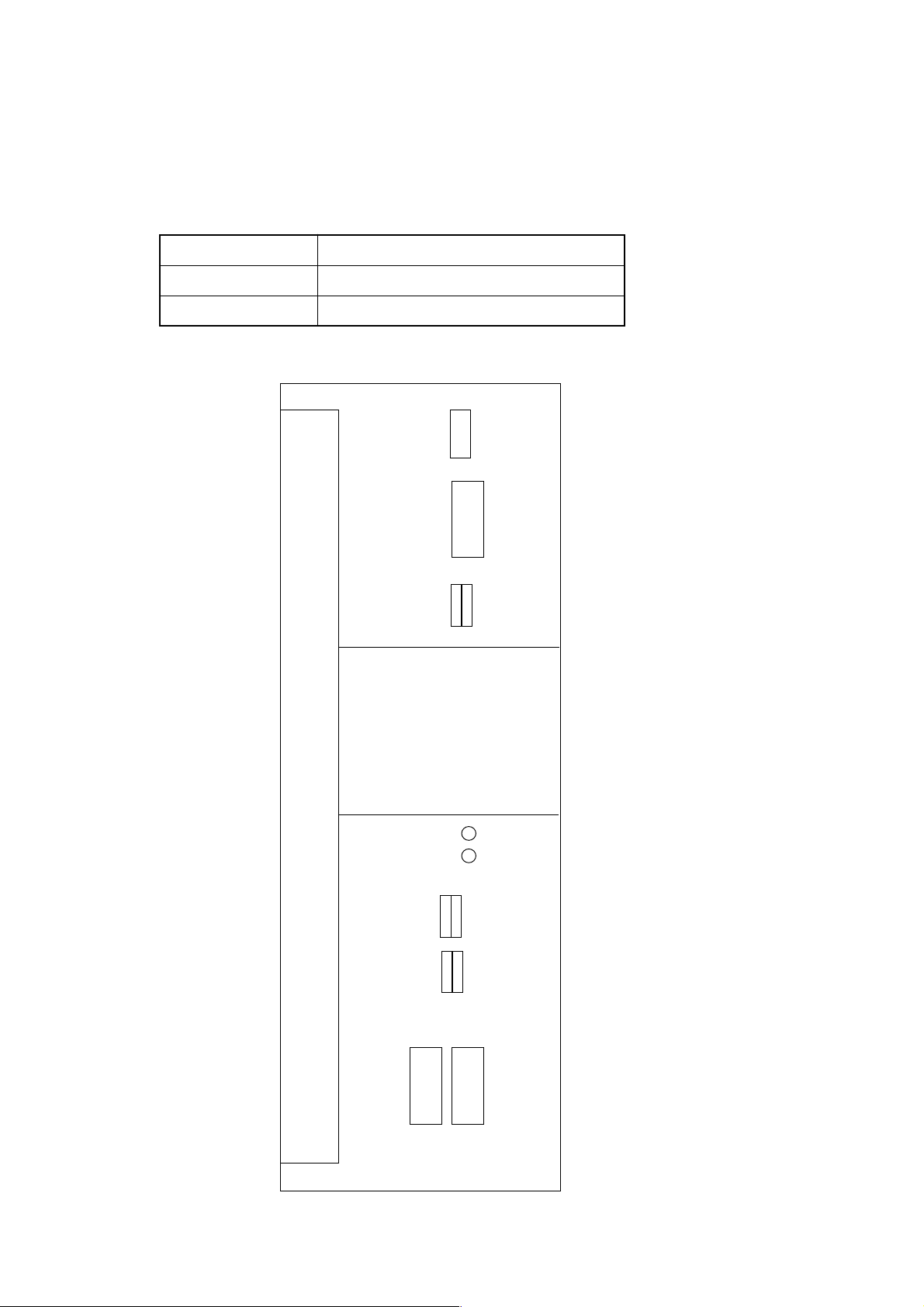
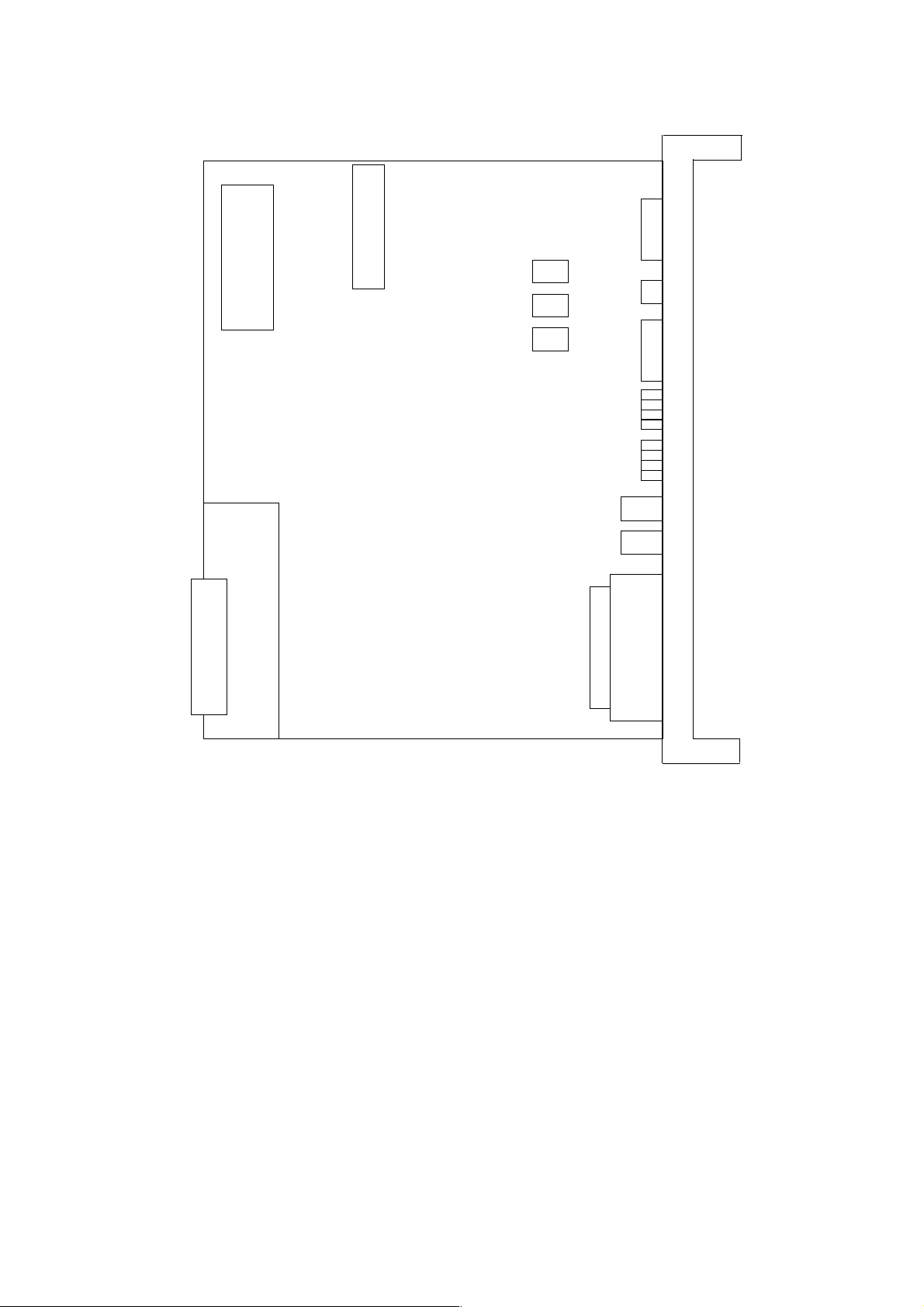
2.2 CPU Board (MAIN)
This is a CNC main CPU board.
Name Type
S-Σ 10M Main CPU Board A16B-3200-0190
S-Σ 10L Main CPU Board A16B-3200-0210
LED
JA1
JA2
JD5A
①
②③
⑩
Boot ROM
⑤⑦⑧
⑥⑨
④
JD5B
JA3
JD1A
JA7A
JA8A
JA4A
JS1A
JS2A
JS3A
JS4A
JS5A
JS6A
JF21
1 - 10
JF22
JF23
JF24
JF26
Page 15
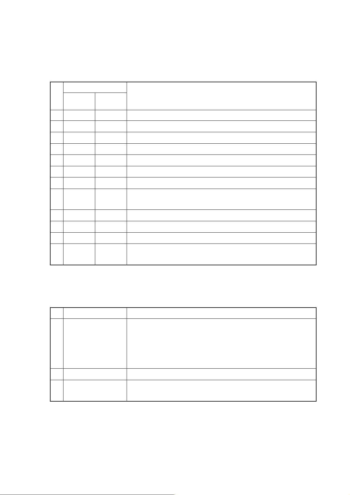
2.2.1 List of Modules
No. Name Function Specification Type
① DRAM module CNC system RAM 8MB A20B-2902-0461
② SRAM module Extension SRAM 256KB A20B-2902-0350
768KB A20B-2902-0351
2.25MB A20B-2902-0352
③ FROM module CNC system, PMC Ladder 8MB A20B-2902-0501
12MB A20B-2902-0500
④ Spindle module Spindle control Serial+Analog A20B-2901-0980
Serial A20B-2901-0981
Analog A20B-2901-0982
⑤ PMC module PMC control With SLC A20B-2902-0480
HSSBC module
⑥
CRTC module Multi (VGA) A20B-2902-0275
⑦ Servo module Servo control 5th and 6th axes
⑧ Servo module Servo control 3rd and 4th axes
⑨ Servo module Servo control 1st and 2nd axes
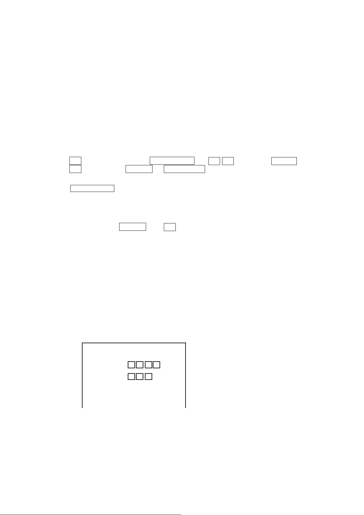
2.2.2 LED Indications
The STATUS LED is green and the ALARM LED is red.
(1) LED indication change at power-on □: Turned off ■: Turned on
LED Indication Description
BTATUS □□□□ The Power is not turned on.
BTATUS ■■■■ The CPU is not starting after turning on the power.
BTATUS ■□■■ Each processor in the system is waiting for ID.
BTATUS □□■■ ID setting for each processor in the system is completed.
BTATUS ■■□■ Completion of FANUC BUS initialization
BTATUS □■□■ Completion of PMC initialization (1)
BTATUS ■□□■ Completion of setting of hardware configuration information for each
BTATUS ■■■□ Completion of initial run of the PMC ladder (PMC-RB)
BTATUS □■■□ Digital servo initialization wait
BTATUS ■□□□ Initial setting is completed and the system is running normally
CRTC text display control
printed circuit board in the system
Standard A20B-2902-0490
(HSSB)
A20B-2902-0070
A20B-2902-0061
1 - 11
Page 16
(2) LED indications for errors
LED Indication Description
STATUS □■□□
ALARM ■■□
STATUS □■□□
ALARM □■■
STATUS □■□□
ALARM □■□
STATUS ■■■■
ALARM ×■×
2.2.3 Connectors
Symbol Name Description
JA1 CRT CRT video signal
JA2 MDI MDI keyboard
JD5A R232-1 RS-232C serial port
JD5B R232-2 RS-232C serial port
JA3 MPG Manual pulse generator
JD1A IOLINK FANUC I/O link
JA7A SPDL-1 Serial spindle
JA8A A-OUT1 Analog output
JA4A APCBAT APC battery
JS1A SERV01 1st axis servo amplifier
JS2A SERV02 2nd axis servo amplifier
JS3A SERV03 3rd axis servo amplifier
JS4A SERV04 4th axis servo amplifier
JS5A SERV05 5th axis servo amplifier
JS6A SERV06 6th axis servo amplifier
JF21 SCALE1 1st axis scale
JF22 SCALE2 2nd axis scale
JF23 SCALE3 3rd axis scale
JF24 SCALE4 4th axis scale
JA26 SV-CHK Servo check
□: Turned off ■: Turned on ×: Irrelevant
The main CPU board has a RAM parity error or the option-2 board
has a servo alarm or RAM parity.
A servo alarm (watchdog timer alarm) occurred.
Other system alarm occurred.
The system is stopping before the CPU is started.
1 - 12
Page 17
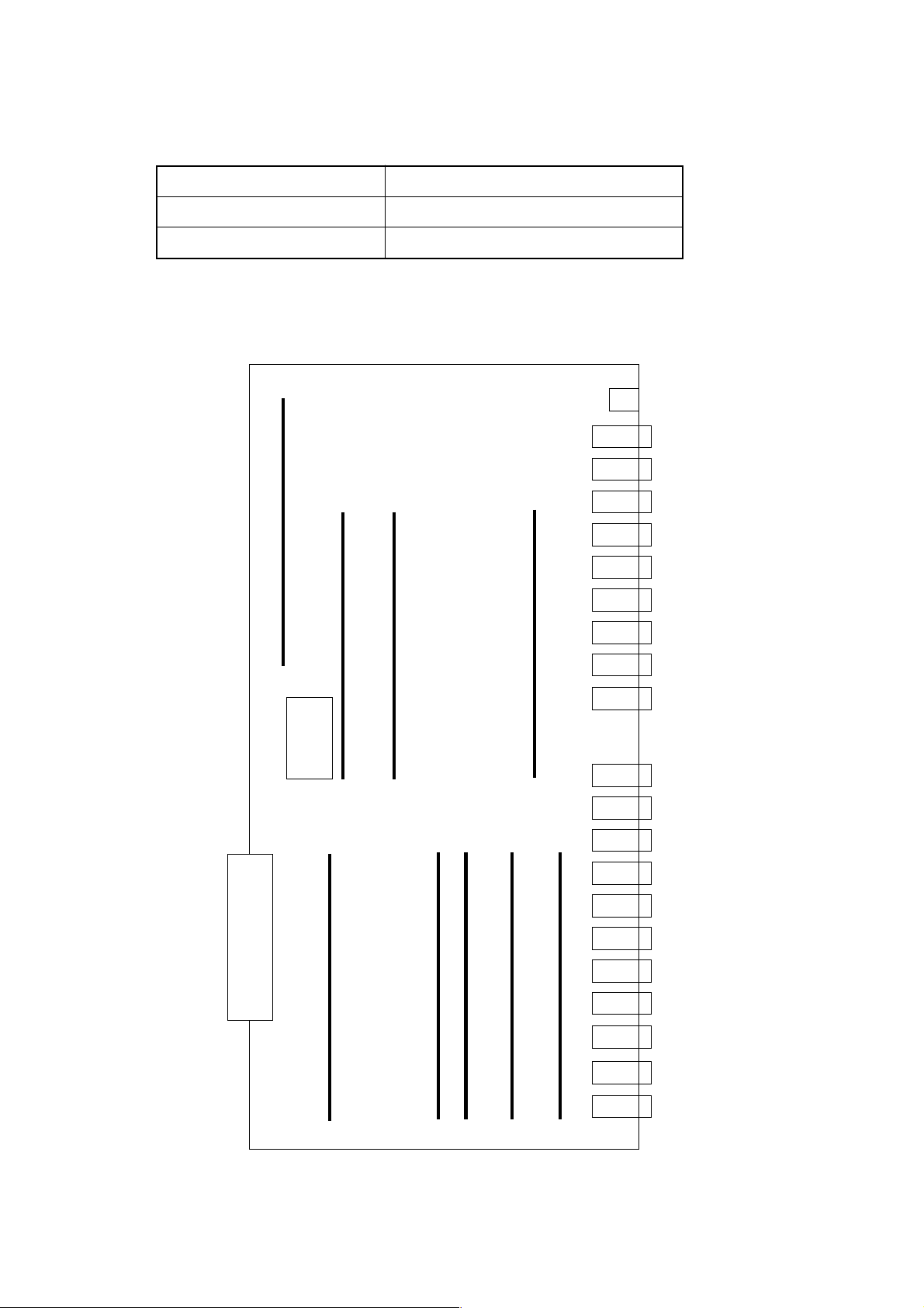
2.3 Option-1 Board (DNC)
This is a DNC operation board.
Name Specification Type
Option-1 Board Remote Buffer A16B-2200-0913
CPU
Communication ROM
JNA
F-BUS
Backplane
Connector
①
LED
JD5C
JD6A
2.3.1 List of Modules
No. Name Function Specification Type
Communication
① Communication control A20B-2901-0361
control module
2.3.2 LED Indications
Indicates the status of the communicating function
STATUS □□□□ (green)
ALARM □□□ (red)
Indication of Communicating Function
□: Turned off ■: Turned on ×: Irrelevant ☆: Blinking
1 - 13
Page 18
LED Indication Description
STATUS ■■■■
ALARM ■□□
STATUS ××□■
ALARM □□□
STATUS ××☆☆
ALARM □□□
2.3.3 Connectors
Symbol Name Description
JD5C R232-3 RS-232C serial port
JD6A R422-1 RS422 serial port
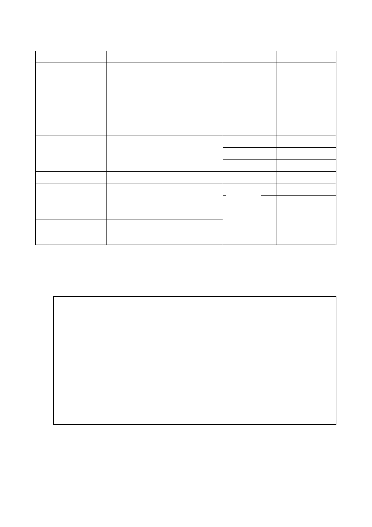
2.4 Option-3 Board (PMC)
This is a sequence control board.
The CPU is not running after turning on the power.
The remote buffer has been initialized and the system is running
normally.
There is an error in communication control of the option-1 board.
Name Specification Type
Option-3 board PMC-RC A16B-3200-0054
LED
JD1A
①
JNA
F-BUS
Backplane
Connector
②
JE5D
JE5E
JE6B
1 - 14
Page 19
2.4.1 List of Modules
No. Name Function Specification Type
① DRAM for PMC
DRAM module
for PMC
② PMC control PMP2 A20B-2901-0960
PMC control
module
2.4.2 LED Indications
Indicates the status of Indicates the status of
the PMC-RC function the CAP-II function
(1) LED indications for the PMC-RC function
A20B-2901-0961
[Not used]
STATUS (green)
ALARM (red)
(a) LED indication change at power-on
□: Turned off ■: Turned on ×: Irrelevant
LED Indication Description
STATUS ■■××
STATUS □□××
STATUS ■■××
STATUS □□××
(b) LED indications for errors
LED Indication Description
STATUS ☆☆××
ALARM □□□
STATUS □☆××
ALARM ■□□
STATUS ☆□××
ALARM □□□
The CPU is not starting after turning on the power.
Waiting for ID setting for each processor in the system
Waiting for completion of initialization of each processor in the
system
Initialization of the PMC-RC function is completed and the system is
running normally.
□: Turned off ■: Turned on ×: Irrelevant ★☆ : Blinking
Other printed circuit board has NMI. (LEDs blinking simultaneously)
Check other printed circuit board for LED indication.
Parity error for the ladder memory or work memory.
Initialize the ladder memory or replace the work RAM module.
A bus error (illegal memory access) occurred.
Replace the option-3 board.
1 - 15
Page 20
LED Indication Description
STATUS ■☆××
ALARM □□□
STATUS ☆■××
ALARM ■□□
STATUS ★☆××
ALARM □□□
2.4.3 Connectors
Symbol Name Description
JD1A IOLINK FANUC I/O LINK
JD5D RS232-4 RS232C
JD5E RS232-5 Unused
JD6B R422-2 Unused
An I/O link has a communication error, etc.
Check a link device or cable.
The PMC control module has a parity error, etc. in it.
Replace the PMC control module.
Checksum error for the system program memory.
The DRAM module for PMC may be defective.
May not be installed
2.5 64-bit RISC Board (RISC) ...... for M
This is a board designed for high-accuracy profile control.
Name Type
64bit RISC board A16B-3200-0150
2.5.1 LED Indications
The STATUS LED is green and ALARM LED is red.
(1) LED indication change at power-on □ : Turned off ■: Turned on
LED Indication Description
STATUS □□□□
STATUS ■■■■
STATUS □□□■
STATUS □□■□
STATUS ■□□□
STATUS ■□□■
STATUS ■□■□
STATUS ■■□□
The power is not turned on.
The RISC CPU is not starting after turning on the power.
The DRAM and SRAM are being tested. (When an error is detected
during a test, this in-test LED indication is held)
The ROM is being tested. (When an error is detected during a test,
this in-test LED indication is held)
Waiting for a request from the main CPU request (1)
Waiting for a request from the main CPU request (2)
Waiting for a request from the main CPU request (3)
Waiting for a request from the main CPU request (4)
1 - 16
Page 21
(2) LED indication while running □: Turned off ■: Turned on
LED Indication Description
STATUS □□□★
STATUS □★□★
STATUS □★★□
STATUS ★□□□
STATUS ★□★★
(3) LED indication for errors □: Turned off ■: Turned on
LED Indication Description
STATUS □□□■
STATUS □□■□
STATUS □□■■
STATUS □■□□
STATUS ■■■□
Waiting for the RISC mode
Waiting for an input of NC statement
Running a command in the RISC mode
Resetting
Override 0 at acceleration/deceleration time before inter-polation
(Waiting for an override change)
An error was detected in testing the DRAM or SRAM on the RISC
board.
An error was detected in testing the ROM module.
A synchronizing signal from the main CPU cannot be detected.
An error was detected in accessing the F-BUS.
System error
(4) ALARM LED indications □ : Turned off ■: Turned on
LED Indication Description
STATUS ■□□
STATUS □■□
STATUS □□■
The RISC CPU is not starting.
SRAM parity
DRAM parity
2.6 MMC-IV BOARD (MMC-IV) ...... Applies only to Multi-Interactive Spec.
This DOS-V personal computer is used in multi-interactive processing. This is a board
designed for high-accuracy profile control.
Name MODEL
MMC-IV BOARD
Note) The conventional and new types of MMC-IV Board are differentiated by use of a
memory card socket.
• Conventional type: With a memory card socket
• New type: Without a memory card socket
A02B-0207-C022 (Conventional type)
A16B-2203-0180 (New type)
2.6.1 SETTING ADJUSTMENT
Since Machine is delivered as having been adjusted prior to shipment, no change is
necessary under normal circumustances.
1 - 17
Page 22
2.6.2 LED DISPLAY
STATUS LED in green color and ALARM LED in red color.
(1) Normal state □ : Turned off ■ : Turned on ×: Irrelevant
LED Indication Description
STATUS □□□□
STATUS ■×××
STATUS ×××■
(2) Abnormal state ■: Turned on ×: Irrelevant
LED Indication Description
STATUS ■××
STATUS ×■×
STATUS ××■
Power OFF state
MMC-IV reset cancelled
HDD access lamp
NMI has occurred in MMC-IV CPU.
Ambient temperature of HDD is either equal to or below 5°C or
equal to or above 55°C.
Parity alarm has occurred in DRAM on the back plane.
2.7 LIQUID CRYSTAL DISPLAY (LCD)
This is a board designed for high-accuracy profile control.
Name SPEC. MODEL
9.5" Monochromatic LCD Without Multi A02B-0222-C110
10.4" Color LCD Without Multi A02B-0222-0150
10.4" Color LCD With Multi A02B-0200-0153
2.7.1 ADJUSTMENT REQUIRED
(1) For A02B-0222-C110 ...... Without Multi Spec./9.5" Monochromatic LCD
VRD 1
DISPLAY, REAR VIEW
1 - 18
Page 23
• VRD1 (Contrast Adjustment)
Through adjustment of VRD1, contrast can be adjusted.
Note
Do not change any setting, volume, etc. other than those mentioned above. A change, if
made in any setting other than the above, results in incorrect screen display.
(2) For A02B-0222-C150 ...... Without Multi Spec./10.4" Color LCD
This display does not include the set pin, volume, etc. for screen adjustment.
Note
Do not change any setting, volume, etc. other than those mentioned above. A change, if
made in any setting other than the above, results in incorrect screen display.
(3) For A02B-0200-C153 ...... With Multi Spec./10.4" Color LCD
T M 1
• • •
SW 1
DISPLAY, REAR VIEW
• TM1 (Flicker Adjustment)
On occurrence of flicker on the screen, change setting of the set pin TM1 into
the other. Normally, flicker can be eliminated in one of these two ways.
• SW1 (Setting of Horizontal Position)
① Use this to shift a display screen horizontally by one dot.
② Use this to set position where all displays are available. There is only one
place for toral display. As it is normally set prior to shipment, no change is
necessary.
Note
Do not change any setting, volume, etc. other than those mentioned above. A change, if
made in any setting other than the above, results in incorrect screen display.
1 - 19
Page 24

2.8 DATA SERVER BOARD
Name MODEL
DATA SERVER BOARD A16B-2202-0630
2.8.1 LED DISPLAY
STATUS LED in green color and ALARM LED in red color.
(1) LED Indications on Supply of Power □ : Turned off ■ : Turned on
No LED 1 2 3 4 DATA SERVER STATE
display
1 STATUS □□□□ Power OFF state
2 STATUS ■■■■ Initial state immediately after supply of power.
3 STATUS □■■■ Main memory test
4 STATUS ■□■■ Ethernet RAM test
5 STATUS □□■■ Common RAM test
6 STATUS ■■□■ Initialization of system area
7 STATUS □■□■ FANUC BUS interrupt test 1
8 STATUS ■□□■ FANUC BUS interrupt test 2
9 STATUS □□□■ FANUC BUS interrupt test 3
10 STATUS ■■■□ FANUC BUS interrupt test 4
11 STATUS □■■□ Initialization of interrupt controller
12 STATUS ■□■□ Initialization BIOS
13 STATUS □□■□ Program loading
14 STATUS ■□□□ Completion of starting of the data server board
When the data server board starts properly, LED display is stopped in “No.14”
state.
Hardware in
checking
Starting of
data serve
software
1 - 20
Page 25
(2) LED Indications on Occurrence of Error (STATUS)
□: Turned off ■: Turned on ×: Irrelevant
“STATUS” LED repeats “LONG” and “SHORT” patterns. The “LONG” pattern is
displayed for a longer time length, while the “SHORT” one for a shorter time
length.
LED DISPLA Y (ST ATUS)
No
LONG
1 2 3 4
1 □□□■ □□■□ Main memory failure. Check the data server board.
2 □□□■ ■□■□ Ethernet RAM failure. Check the data server board.
3 □□□■ □■■□ Common RAM failure. Check the data server board.
4 ■□□■ ×××× An invalid interrupt has been given to CPU.
5 □■□■ ×××× An invalid interrupt has been given to CPU.
6 ■■□■ ×××× An invalid interrupt has been given to CPU.
7 □■■■ ■□□□ A system error has occurred in the data server board.
8 □□■■ ■□□□ A bus error has occurred in FUNUC BUS. Check the data
SHORT
1 2 3 4
server board.
DATA SERVER STATE
9 □□■■ □■□□ A parity error has occurred in the main memory.
10 □□■■ ■■□□ A parity error has occurred in the Ethernet RAM.
11 □□■■ □□■□ A parity error has occurred in the Common RAM.
12 □□■■ ■□■□ “Refresh” to the main memory has ceased for a time longer
than the set length.
(3) LED Display on Occurrence of Error (ALARM)
■: Turned on ×: Irrelevant
No LED DISPLAY 1 2 3 DATA SERVER STATE
1 ALARM ■×× Either a parity error has occurred in any of the main memory,
Ethernet RAM, and Common RAM, or “refresh” to the main
memory has ceased for a time longer than the set length.
Referring to “STATUS” LED NO’s 9 to 12, identify the failure
and replace the part.
2 ALARM ×■× Fuse is gone. Replace a fuse.
3 ALARM ××■ CPU is in Halt or SHUTDOWN state.
Check the board.
1 - 21
Page 26

2.8.2 REPLACEMENT OF FUSE
(1) Check the fuse on the front panel of the data server board for any disconnection.
On occurrence of disconnection, a white marker appears in a small window of the
fuse.
(2) Remove the cause which has disconnected the fuse.
(3) Pulling out the disconnected fuse, insert a new one of the same specification.
STATUS
ALARM
F 1
2.0A
Fuse
Fuse specification: A08B-0048-K101
Capacity:2.0A
Application: For Ethernet supply power
1 - 22
Page 27
2.9 LIST OF UNITS AND PRINT BOARDS
2.9.1 CONTROL UNIT RACK
NAME SPECIFICATIONS TYPE
S-Σ 10L
CONTROL UNIT
RACK
S-Σ 10L
CONTROL UNIT
RACK
2.9.2 POWER UNIT
NAME TYPE
POWER UNIT AI A16B-1212-0901
POWER UNIT BI A16B-1212-0871
2.9.3 CONTROL UNIT P.C.B.
MMC-IV not
provided
MMC-IV
provided
MMC-IV not
provided
MMC-IV
provided
6 slots A02B-0200-C003
8 slots A02B-0200-C004
6 slots A02B-0200-C011
8 slots A02B-0200-C012
4 slots A02B-0129-C002
6 slots A02B-0129-C003
4-slots A02B-0129-C010
6 slots A02B-0129-C011
NAME SPECIFICATIONS TYPE
MAIN CPU BOARD
OPTION 1 BOARD
OPTION 3 BOARD
HIGH-SPEED SKIP
SIGNAL INPUT BOARD
CONTROL UNIT
GRAPHIC BOARD
64-BIT RISC BOARD
DATA SERVER BOARD
MC-IV BOARD
S-Σ 10M
S-Σ 10L
REMOTE BUFFER
PMC-RC
MULTIINTERACTIVE
A16B-3200-0190
A16B-3200-0210
A16B-2200-0913
A16B-3200-0054
A16B-2200-0954
A20B-8001-0480
A16B-3200-0150
A16B-2202-0630
A02B-0207-C022
(Conventional type)
A16B-2203-0180
(New type)
1 - 23
Page 28
3. TROUBLESHOOTING
When a trouble happened, check “when it happened,” “what you were operating,” “what it
was like,” and “how often it happens.”
3.1 T racking through the ALARM Screen
When an alarm happened during operation, an alarm message appears on the top area
of the screen.
For some alarms, the details are displayed on the diagnostic screen. Confirm, then, the
description on the diagnostic screen in the following operation:
[Display Operation of Diagnostic Screen]
While NC “General Screen” is displayed, operate as:
(OPER./MAINTE) → F4 SYSTEM →3 0 (F MENU) INPUT →
△
2 (F_SYSTEM) INPUT → F7 DGNOS
to display the diagnostic screen. Input, then, a number to be referred to and push
F6 NO.SRH . Data for the diagnostic number are displayed. (The page key is
useable to make a change.)
(Note 1) When the diagnostic function does not appear in F7 following “F SYSTEM”
being selected in the above operation, push (RETURN) a few times.
(Note 2) Use ALTER , not (RETURN), for return operation from the
diagnostic screen.
△
3.2 Tracking through the Controller’s Monitor LEDs
Each unit in the controller has monitor LEDs so that you can check for the status of each
unit. For details, see 2. FUNCTIONS AND HANDLING OF CONTROL UNITS.
Each Unit
STATUS
ALARM
1 - 24
Page 29
4. POWER-ON ADJUSTMENT
4.1 Power-on Procedure
①Enter (set) the PMC ladder and others.
②Enter (set) the NC parameters.
③Turn off the power and turn it on again.
(Note) When system software has not been entered into the NC internal memory,
transfer it into the NC internal memory according to the instructions in
[APPENDIX] BOOT SYSTEM, and then, go through the above-mentioned
steps.
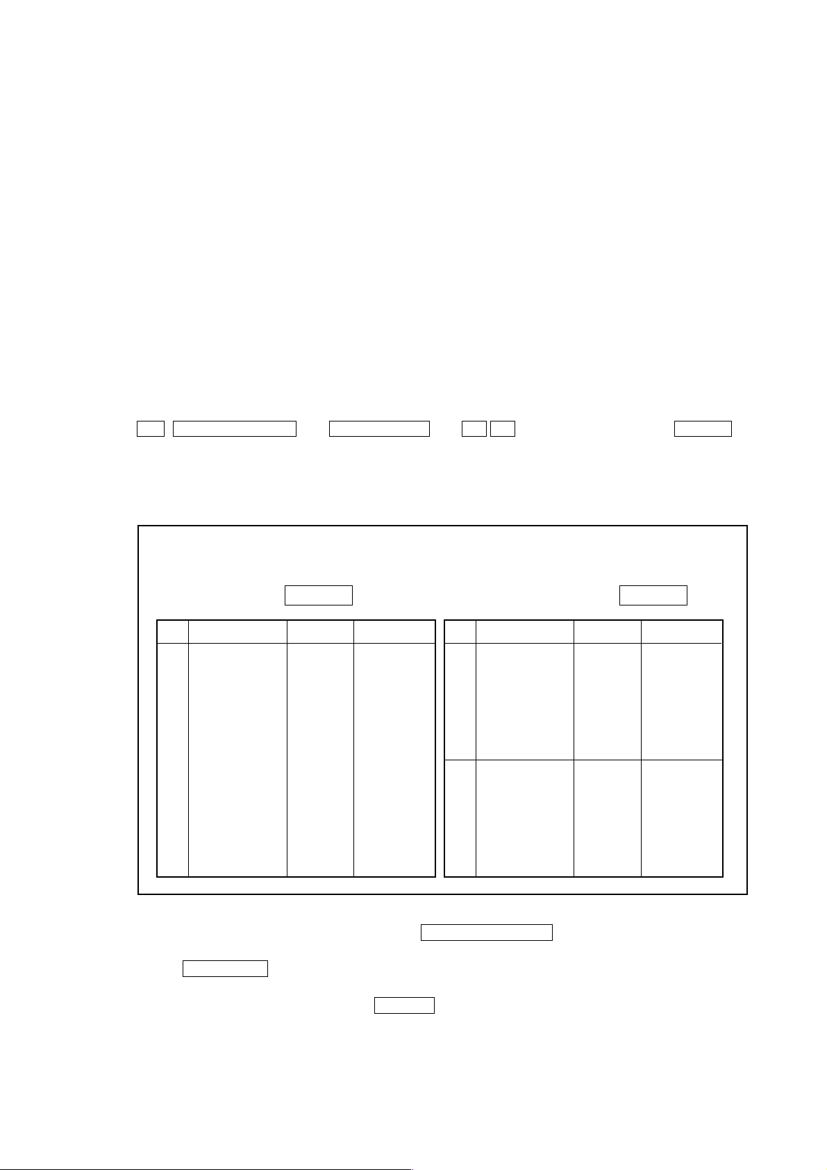
4.2 System Table
This CNC unit sets allocations of the data areas such as machining program, tool offset
amount through the "system table."
To display the System Table screen, operate in the following order in the Overall screen:
OPER./MAINTE → F4/SYSTEM → 2 5 (SYSTEM TABLE) → INPUT
△
SYSTEM T ABLE
BASIC RAM SIZE 38E40 EXT. RAM SIZE 0
No. TABLE SIZE OFFSET No. TABLE SIZE OFFSET
01 SYSTEM 10000 0 11 0 0
02 TOOL 5000 0 12 0 0
03 SPARE 3900 0 13 0 0
04 MONI 6F00 0 14 0 0
05 PRGRM 13000 0 15 DUMMY 6600 32800
06 0 0 16 0 0
07 0 0 17 0 0
08 0 0 18 0 0
09 0 0 19 0 0
10 0 0 20 0 0
When initially starting up the system, press F5/SYSTEM CLR to initialize the system.
When this is done, the basic RAM capacity and extended RAM capacity are automaticlly set.
Pressing F3/TABLE brings the cursor into the table. In accordance with the names versus
capacities table provided on the next page, set the table names and capacities, using
[Cursor] and [Alphanumeral] plus the INPUT key.
1 - 25
Page 30

(Note 1) The numbers 01 through 15 are the tables for the basic RAM, and 16 through
20 are those for the extended RAM. When the extended RAM capacity is 0
(zero), do not set for the numbers 16 through 20.
(Note 2) Set the capacity in an increment of 100, suffixing a numeral with “H” (indicates
hexadecimal)
(Note 3) If the capacity is entered, the offset for the next table will be automatically set.
Different from the S-III, however, the last table capacity is not adjusted. Set a
dummy table before the last table capacity so that it will be of specified
capacity.
(Note 4) The table number 01 has a fixed table name, “SYSTEM,” and capacity,
“1000H.” For the other tables, you can set any table names in any places.
(Note 5) A standard set value varies from one model to another. When actually setting
it, follow the materials for each model.
(Note 6) When the system table is changed, be sure to turn off and on the power to
make sure that “790 System Table Error” does not occur, and then, start
1 - 26
Page 31

operating the system.
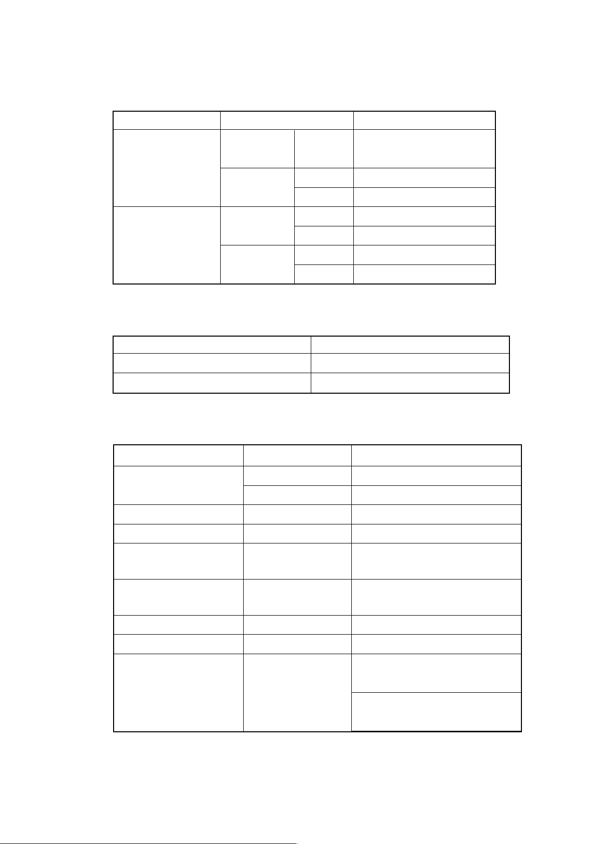
Function Table Spec.
System Data
Tool offset
Tool life
management
Cutting
monitoring
Machining
program
SYSTEM 10000H
TOOL 200 pairs 2800H 5000H
SPARE 200 pairs 2000H
MONI 200 pairs 4800H
PRGRM 1,000m 6F000H
Capacities
Σ 10M Σ 10L
32 pairs 600H C00H
64 pairs C00H 1400H
100 pairs 1400H 2800H
400 pairs 5000H
500 pairs 5E00H
1,000 pairs BC00H
32 pairs B00H
64 pairs F00H
100 pairs 1300H
400 pairs
500 pairs 3900H
1,000 pairs
32 pairs 2800H
64 pairs 2E00H
100 pairs 3500H
400 pairs
500 pairs 6F00H
1,000 pairs
80m A000H
160m 13000H
320m 24000H
500m 37000H
640m 4A000H
1,280m 8B000H
2,000m D5000H
2,560m 10E000H
4,000m 1A1000H
5,120m 200000H
400H
2000H
Remarks
Table No. 01 Fixed
The 100 pairs in the Spec.
column represents;
M-system: 100 pairs
L-system: 99 pairs
The Spec. column
represents the number of
tool offset pairs.
The spec. column
represents the number of
tool offset pairs.
The maximum number of
registerable programs is
irrelevant.
High-precision
contour control
Automatic
program
(Multi-interactive)
HPCC 10000H
3800H
TLFILE
1 - 27
3500H
5100H
6600H
M-system only
NR/TG turning only
NR/TG turning + rotation
CA
Page 32

4.3 SLBUS Table
In order to allocate the addresses for the input signals (X contact) and output signal (Y
contact) on the part of the machine, itis necessary to set ths SLBUS table.
To display the SLBUS TABLE screen, operate as follows in the OVERALL screen.
[ ] (OPRE/MAINTE) → [F4/SYSTEM] → [2][4](SLBUS) → [INPUT]
SLBUS TABLE
△
Lead Ch. Chanels Bytes Address
No. Loc# Type Slave Division
Buffer Size IN OUT IN OUT IN OUT
01 00 0 00 00 00 00 00 00 F0 F0
02 00 0 01 01 02 00 00 10 00 00
03 00 0 00 00 00 00 00 00 00 00
04 00 0 00 00 00 00 00 00 00 00
05 00 0 00 00 00 00 00 00 00 00
06 00 0 00 00 00 00 00 00 00 00
07 00 0 00 00 00 00 00 00 00 00
08 00 0 00 00 00 00 00 00 00 00
09 00 0 00 00 00 00 00 00 00 00
10 00 0 00 00 00 00 00 00 00 00
11 00 0 00 00 0000 0000 0000
12 00 0 00 00 00 00 00 00 00 00
13 00 0 00 00 00 00 00 00 00 00
14 00 0 00 00 00 00 00 00 00 00
15 00 0 00 00 00 00 00 00 00 00
16 00 0 00 00 00 00 00 00 00 00
High
Speed
To alter the set value, press [F9/ALTER]. The message, “DO YOU WANT TO ALTER
? (Y/N),” is messaged. Press [Y]. Aframe cursor appears in the table, allowing you to
alter the set value. Make setting according to the machine specifications.
When you start up the system for the first time, press [F8/CLEAR ALL] to initialize the
data, and then, set each item.
After alteration is completed, press [F9/REFER] to end the setting mode.
1 - 28
Page 33

5. DAILY MAINTENANCE AND INSPECTION
5.1 Replacing the Battery
[WARNING]
Turn on the power for the machine (CNC), press the EMERGENCY STOP switch, and
then, replace the battery. Since this work is carried out with the cabinet left open in the
power-on state, only personnel who has been trained on maintenance and safety
should do it.
When opening the cabinet to replace the battery, do not touch a high-voltage circuit. If
the cover is not in place and you touch there, you will get an electric shock.
5.1.1 CNC Memory Backup Battery
The CNC is provided with batteries for retaining memory to store programs, offset
volumes, parameters, etc. When battery voltage has lowered, “794 BATTERY
ALARM” warning is displayed. On appearance of the warning, change batteries as
soon as possible. Try not to turn off the CNC unit as much as possible until the battery
is replaces.
(1) CNC memory backup battery replacement procedure
① Turn on the power for the machine (CNC). (Note)
② Remove a battery case located on the front panel of the power unit. Hold down
the top of the case and pull it to your side to remove it.
③ Disconnect a connector attached to the battery.
④ Replace the battery and put back the connector.
⑤ Reattach the battery case.
⑥ Turn off the power for the machine (CNC).
CNC Controller
Power Unit
Front Panel
Lithium Battery
Battery Case
A02B-0200-K102 (For Power Sources AI and BI)
A02B-0200-K106 (For Power Sources C)
1 - 29
Page 34

[Note]
Whether the CNC is turned on or off, the battery can be replaced. When replacing it
with the CNC turned off, however, complete replacement within 30 minutes. If the
battery has been removed for 30 minutes or more with the power turned off, the
contents of the CNC memory may be lost. When the contents of the memory are lost
this way, a RAM PARITY system alarm may occur to disable the CNC, even if it is
turned on.
5.1.2 Replacing the Absolute Encoder Battery
When the machine has an absolute encoder such as absolute pulse coder or absolute
linear scale, an absolute encoder battery has been installed in addition to a memory
backup battery.
When an APC alarm no. F307 or no. F308 occurs, replace the battery as soon as
possible. Unless it is replaced, an absolute position will be lost and you will have to
manually operate reference point return again.
(1) Absolute encoder battery replacement procedure (α series servo amplifier
module)
① Turn on the power for the machine (CNC).
② Remove a battery case located on the front of a α series servo amplifier
module (SVM). Hold the top and bottom of the case and pull it to your side.
③ Disconnect a connector attached to the battery.
④ Replace the battery and put back the connector.
⑤ Reattach the battery case.
⑥ Turn off the power for the machine (CNC).
Battery Case
α Series
SVM
Connector CX5X
Connector
1 - 30
Battery
A06B-6073-K001
Page 35

(2) Absolute encoder battery replacement procedure (Separate pulse coder)
① Turn on the power for the machine (CNC).
② Unscrew the battery case and remove the cover.
③ Replace the dry cells in the case. Set two each of dry cells in different
directions.
④ After replacing the dry cells, put back the cover.
⑤ Turn off the power for the machine (CNC).
Screws
Cover
[Note]
Replace the battery with the CNC turned on. If the battery is replaced with the power
turned off, a memorized absolute position will be lost.
1 - 31
Page 36

I-II SEICOS
1. OVERVIEW
1.1 System Configuration
1.2 Hardware Overview
2. PCB CONNECTORS AND CARD CONFIGURATION
2.1 S-Σ 16/18/21 Mother Boards
2.2 Inverter PCBs
2.3 Serial Communication Board (Remote Buffer)/C Language Board
2.4 RISC Board
2.5 Data Server Board
2.6 List of Unit and PCBs
3. TROUBLESHOOTING
3.1 Tracking through the ALARM Screen
ΣΣ
Σ 16/18/21 UNIT
ΣΣ
4. POWER-ON ADJUSTMENT
4.1 Power-on Procedure
4.2 System Table
4.3 SLBUS T able
5. DAILY MAINTENANCE AND INSPECTION
5.1 Replacing the Battery
5.2 Replacing the Fuse for the Control Unit
5.3 Replacing the Fan Motor
5.4 Adjusting the Contrast of the Monochrome Display
1 - 32
Page 37

1. OVERVIEW
The SEICOSΣ 16/18/21 CNC system is a more compact high-reliability unit provided with
up-to-date device technology and integrates a display unit and an NC unit.
1.1 System Configuration
The following figure shows a system example using the SEICOS Σ 16/18/21 CNC unit.
CONTROL/LCD Unit
Optical Cable
Spindle Amp.
I/O LINK
Servo Amps.
CNC Keyboard
SLBUS
Conversation
Module
SLBUS
SLBUS
Distribution Board
Spindle
Motor
Servo
Motor
Servo
Motor
1 - 33
I/O Slaves
Servo
Motor
Page 38

1.2 Hardware Overview
1
1
1
1
1
1
1
1234567890123456789012345678901212345678901234
1
4
1
4
1
4
1
4
1
4
1
4
1
4
1234567890123456789012345678901212345678901234
1234567890123456789012345678901212345678901234
1
4
1
4
1
4
1
4
1
4
1
4
1
4
1234567890123456789012345678901212345678901234
1234567890123456789012345678901212345678901234
1
4
1
4
1
4
1
4
1
4
1
4
1
4
1234567890123456789012345678901212345678901234
1234567890123456789012345678901212345678901234
1
4
1
4
1
4
1
4
1
4
1
4
1
4
1234567890123456789012345678901212345678901234
1.2.1 SEICOS
23456789012345678901234567890121234567890123
23456789012345678901234567890121234567890123
23456789012345678901234567890121234567890123
23456789012345678901234567890121234567890123
23456789012345678901234567890121234567890123
23456789012345678901234567890121234567890123
Serial Communication Board
23456789012345678901234567890121234567890123
Remote Buffer (DNC)
23456789012345678901234567890121234567890123
23456789012345678901234567890121234567890123
23456789012345678901234567890121234567890123
23456789012345678901234567890121234567890123
23456789012345678901234567890121234567890123
23456789012345678901234567890121234567890123
23456789012345678901234567890121234567890123
(S- ƒ°16M Only)
23456789012345678901234567890121234567890123
23456789012345678901234567890121234567890123
23456789012345678901234567890121234567890123
23456789012345678901234567890121234567890123
Data Server Board
23456789012345678901234567890121234567890123
23456789012345678901234567890121234567890123
23456789012345678901234567890121234567890123
Data Server Function
ΣΣ
Σ 16
ΣΣ
RISC Board
Option
23456789012345678901234567890121234567890
23456789012345678901234567890121234567890
23456789012345678901234567890121234567890
23456789012345678901234567890121234567890
23456789012345678901234567890121234567890
23456789012345678901234567890121234567890
23456789012345678901234567890121234567890
Mother Board
CNC Control CPU
• 2- to 8-axis Control
• Spindle Interface
• LCD/MDI
• I/O Link
• PMC-RB5/-RB6
• Analog Output/
High-speed DI
• RS-232C x 2
• Memory Card Interface
Basic System
Control/LCD Unit
23456789012345678901234567890121234567890123
23456789012345678901234567890121234567890123
23456789012345678901234567890121234567890123
23456789012345678901234567890121234567890123
C Language Board
23456789012345678901234567890121234567890123
23456789012345678901234567890121234567890123
23456789012345678901234567890121234567890123
C Language Function
for PMC
No Option Slots, or 2, 3,
or 4 Slots (Note)
(Note) If there are 3 or 4 slots provided, only the RISC board can be installed in the
2nd slot (center) of the 3 slots and in the 4th slot (farthest from the LCD) of the
4 slots, respectively.
1 - 34
Page 39

1.2.2 SEICOS
2
2
2
2
2
2
2
4
4
4
4
4
4
4
4
4
4
4
4
4
4
4
4
4
4
4
4
4
23456789012345678901234567890121234567890123
23456789012345678901234567890121234567890123
23456789012345678901234567890121234567890123
23456789012345678901234567890121234567890123
23456789012345678901234567890121234567890123
Serial Communication Board
23456789012345678901234567890121234567890123
23456789012345678901234567890121234567890123
Remote Buffer (DNC)
23456789012345678901234567890121234567890123
23456789012345678901234567890121234567890123
23456789012345678901234567890121234567890123
23456789012345678901234567890121234567890123
23456789012345678901234567890121234567890123
Data Server Board
23456789012345678901234567890121234567890123
23456789012345678901234567890121234567890123
ΣΣ
Σ 18
ΣΣ
234567890123456789012345678901212345678901
234567890123456789012345678901212345678901
234567890123456789012345678901212345678901
234567890123456789012345678901212345678901
234567890123456789012345678901212345678901
234567890123456789012345678901212345678901
234567890123456789012345678901212345678901
Mother Board
CNC Control CPU
• 2- to 6-axis Control
• Spindle Interface
• LCD/MDI
• I/O Link
• PMC-RB5/-RB6
• Analog Output/
High-speed DI
• RS-232C x 2
• Memory Card Interface
Basic System
Data Server Function
Option
Control/LCD Unit
23456789012345678901234567890121234567890123
23456789012345678901234567890121234567890123
23456789012345678901234567890121234567890123
23456789012345678901234567890121234567890123
C Language Board
23456789012345678901234567890121234567890123
23456789012345678901234567890121234567890123
23456789012345678901234567890121234567890123
C Language Function
for PMC
No Option Slots, or 2, 4,
or 4 Slots (Note)
(Note) If there are 4 slots provided, the 4th slot (farthest from the LCD) is not
available.
1 - 35
Page 40

1.2.3 SEICOS
1
1
1
1
1
1
1
5
5
5
5
5
5
5
ΣΣ
Σ 21
ΣΣ
23456789012345678901234567890121234567890
23456789012345678901234567890121234567890
23456789012345678901234567890121234567890
23456789012345678901234567890121234567890
23456789012345678901234567890121234567890
23456789012345678901234567890121234567890
23456789012345678901234567890121234567890
Mother Board
CNC Control CPU
• 2- to 4-axis Control
• Spindle Interface
• LCD/MDI
• I/O Link
• PMC-RA5
• Analog Output/
High-speed DI
• RS-232C x 2
• Memory Card Interface
Basic System
234567890123456789012345678901212345678901234
234567890123456789012345678901212345678901234
234567890123456789012345678901212345678901234
234567890123456789012345678901212345678901234
234567890123456789012345678901212345678901234
Serial Communication Board
234567890123456789012345678901212345678901234
234567890123456789012345678901212345678901234
Remote Buffer (DNC)
Option
Control/LCD Unit
No Option Slots, or 2 Slots
1 - 36
Page 41

2. PCB CONNECTORS AND CARD CONFIGURATION
2.1 Mother Boards
2.1.1 Specification
Name Specification
S-Σ 16 Mother Boards A20B-8100-0130
S-Σ 18 Mother Boards A20B-8100-0135
S-Σ 21 Mother Boards A20B-8100-0136
(PMC-RA5)
2.1.2 Connector Applications
Connector No. Application
COP10A Servo motor (FSSB)
CA55 MDI (CNC keyboard)
CA54 Servo check
JD36A RS-232C serial port 1
JD36B RS-232C serial port 2
JA40 Analog output/high-speed DI
JD1A I/O link
JA41 Serial spindle/position coder
CP1B 24 V DC-OUT
CP1A 24 V DC-IN
JNA F-BUS interface
CN8B Video signal interface
MCRD1 PCMCIA (memory card) interface
1 - 37
Page 42

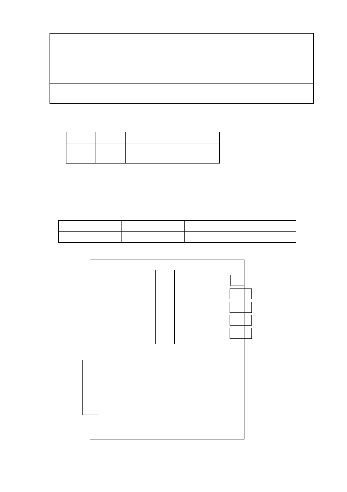
2.1.3 Connector Mounting Positions
(COP10A is a connector located
above the server card)
Inverter PCB
Battery
Rear of Unit
Mother Board
Mother Board
1 - 38
Page 43

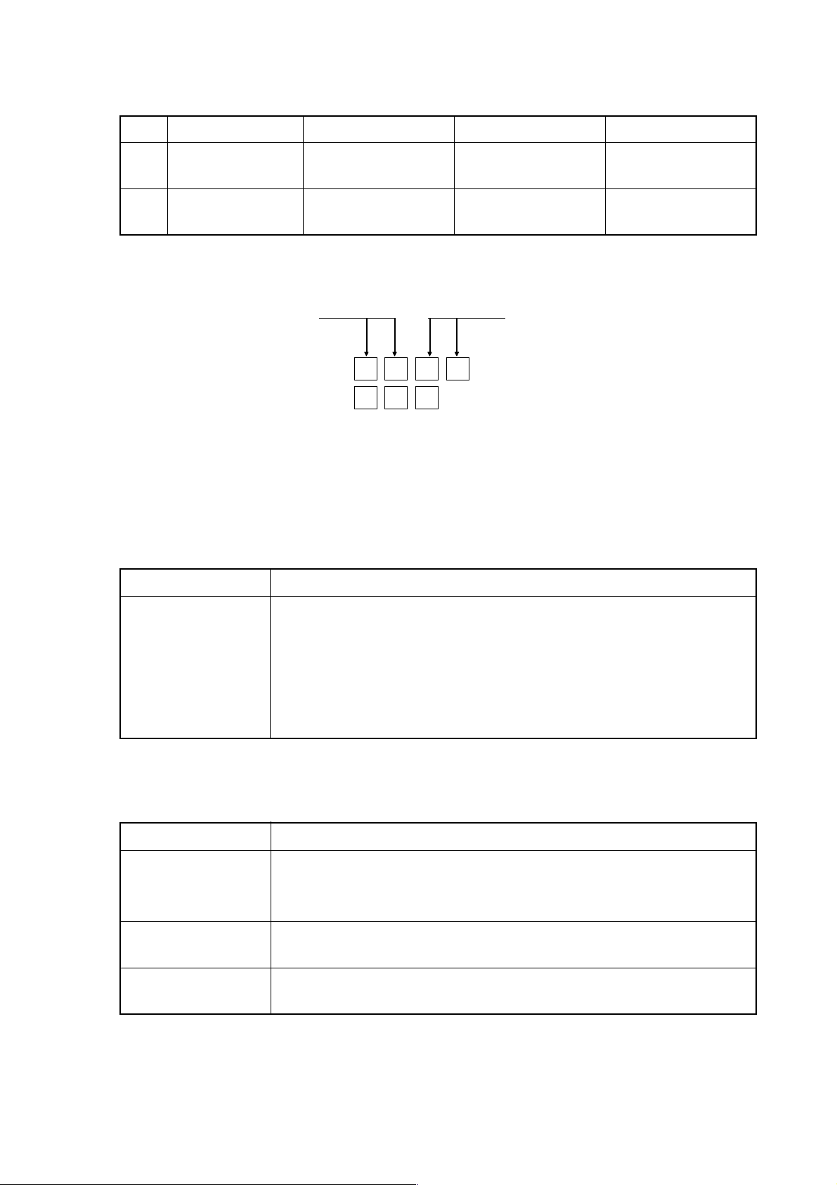
2.1.4 Card Mounting Positions
①Axis
Control Card
No Name Specification Function Remark
① A17B-3300-0100
Axis control
card
② Display
Contorol Card
Axis control
③
CPU Card
Mother Board
8 axes (Allowed only for
Σ 16)
A17B-3300-0101
A20B-3300-0030
A20B-3300-0031
② A20B-3300-0020
Display control
card
③ A20B-3300-0050
CPU card
A20B-3300-0023
A20B-3300-0070
Text display/
graphic display
CNC control
6 axes (Allowed only for
Σ 16/18)
4 axes
2 axes
10.4-inch color
9.5-inch monochrome
Pentium (Σ 16/18)
486DX2 (Σ 21)
1 - 39
Page 44

2.1.5 DIMM Module Mounting Positions
(1) FROM/SRAM module
② SRAM Module①From Module
DIMM Module Socket
Mother Board
No Name Specification Function Remark
① A20B-3900-0010
FROM module
A20B-3900-0011
A20B-3900-0012
② A20B-3900-0020
SRAM module
A20B-3900-0060
A20B-3900-0061
A20B-3900-0052
CNC system,
Servo system,
PMC ladder
System SRAM
graphic display
16 M (Allowed only for Σ
16/18)
12 M (Allowed only for Σ
16/18)
8 M
3 M
(Allowed only
2 M
for Σ 16/18)
1 M
512 K
1 - 40
Page 45

(2) DRAM module
③ DRAM Module
Connector
CPU Card
Side B
No Name Specification Function Remark
① A20B-3900-0040
DRAM module CNC System RAM 12 M (Allowed only for Σ
A20B-3900-0041
DIMM Module Socket
16/18)
8 M
1 - 41
Page 46

2.2 Inverter PCBs
2.2.1 Specifications
Inverters 10.4" color (For 0 or 2 slots) A20B-2002-0500
10.4" color (For 4 slots) A20B-8100-0200
9.5" monochrome (For 0 or 2 slots) A20B-2002-0480
9.5" monochrome (For 4 slots) A20B-2002-0550
2.2.2 Connector Mounting Positions
(1) Overall
Name Specification
Battery
Rear of Unit
CP8
CN39A CN39B
Inverter PCB
1 - 42
Mother Board
Page 47

(2) PCB alone
① With no slots or 2 slots
CN39A CN39B
CP1
CN3
② With 4 slots
CN39BCN39A
CP1
Connector No. Application
CN39A Fan power
CN39C CN39D
CN3
CP8
CP8
CN39B
CN39C
CN39D
CP8 Battery
CP1 LCD backlight power
CN3 Inverter PCB power
1 - 43
Page 48

2.3 Serial Communication Board (Remote Buffer)/C Language Board
2.3.1 Specifications
Name Specification Remark
Serial communication board
A (Remote buffer)
C language board
2.3.2 Connector Mounting Positions
(1) Serial communication board A (Remote buffer)
JNA
F-BUS Back Plane Connector
A20B-8100-0152
A20B-8100-0151 Allowed only for Σ 16/18
JD28A
JD6A
Connector No. Application
JD28A RS-232C serial port
JD6A RS-422 serial port
(2) C language board
JNA
F-BUS Back Plane Connector
(Note) The C language board has no connectors to link to the outside.
1 - 44
Page 49

2.3.3 Card Mounting Position
5
5
5
5
5
5
5
5
5
5
5
5
5
5
23456789012345678901234
23456789012345678901234
23456789012345678901234
23456789012345678901234
23456789012345678901234
23456789012345678901234
23456789012345678901234
23456789012345678901234
23456789012345678901234
23456789012345678901234
23456789012345678901234
23456789012345678901234
23456789012345678901234
23456789012345678901234
Connector
DIMM Module Socket
(Mounted onto the CPU Card)
JD28A
JD6A
CPU Card
Name Specification Function Remark
CPU Card A20B-3300-0070 486DX2
Serial communication function, PMC
C language function
1 - 45
Page 50

2.4 RISC Board
2.4.1 Specifications
Name Specification Remark
RISC board A20B-8100-0170 Allowed only for Σ 16M allowed
2.4.2 Connector Mounting Positions
JNA
F-BUS Back Plane Connector
(Note) The RISC board has no connectors to link to the outside.
2.4.3 Card Mounting Position
(Note) No cards are mounted onto the RISC board.
1 - 46
Page 51

2.5 Data Server Board
12345678901234
1
4
1
4
1
4
1
4
1
4
1
4
1
4
1
4
1
4
1
4
1
4
1
4
1
4
1
4
1
4
1
4
1
4
1
4
12345678901234
2.5.1 Specifications
Name Specification Remark
Data server board
2.5.2 Connector Mounting Positions
JNA
F-BUSQ Back Plane Connector
CNH1
* CD27 is mounted above the ADD-ON board.
A20B-8100-0160 Allowed only for Σ 16/18
ADD-ON Board
234567890123
234567890123
234567890123
234567890123
234567890123
234567890123
234567890123
234567890123
234567890123
234567890123
234567890123
234567890123
234567890123
234567890123
234567890123
234567890123
234567890123
234567890123
CD27
Connector No. Application
CNH1 IDE hard disk interface
CD27 AUI interface
2.5.3 Card Mounting Position
(Note) No cards are mounted onto the data server board.
1 - 47
Page 52

2.6 List of Units and PCBs
2.6.1 Basic Units
Model Unit Name Drawing No. Remark
Σ16 No slots A02B-0236-C511 Soft keys (10 + 2)
Basic unit A4, 10.4" color
Basic unit A5, 10.4" color
Basic unit A6, 10.4" color
Basic unit A32, 10.4"
color
Basic unit A13, 9.5"
monochrome
Basic unit A14, 9.5"
monochrome
Basic unit A15, 9.5"
monochrome
Basic unit A35, 9.5"
monochrome
Σ18 No slots A02B-0238-C511 Soft keys (10 + 2)
Σ21 No slots A02B-0247-C515 Soft keys (10 + 2) RA5
Basic unit A4, 10.4" color
Basic unit A5, 10.4" color
Basic unit A6, 10.4" color
Basic unit A32, 10.4"
color
Basic unit A13, 9.5"
monochrome
Basic unit A14, 9.5"
monochrome
Basic unit A15, 9.5"
monochrome
Basic unit A35, 9.5"
monochrome
Basic unit A13, 10.4"
color
Basic unit A14, 10.4"
color
Basic unit A17, 9.5"
monochrome
Basic unit A18, 9.5"
monochrome
2 slots A02B-0236-C512 Soft keys (10 + 2)
4 slots A02B-0236-C513 Soft keys (10 + 2)
3 slots A02B-0236-C518 Soft keys (10 + 2)
No slots A02B-0236-C541 Soft keys (10 + 2)
2 slots A02B-0236-C542 Soft keys (10 + 2)
4 slots A02B-0236-C543 Soft keys (10 + 2)
3 slots A02B-0236-C548 Soft keys (10 + 2)
2 slots A02B-0238-C512 Soft keys (10 + 2)
4 slots A02B-0238-C513 Soft keys (10 + 2)
3 slots A02B-0238-C518 Soft keys (10 + 2)
No slots A02B-0238-C541 Soft keys (10 + 2)
2 slots A02B-0238-C542 Soft keys (10 + 2)
4 slots A02B-0238-C543 Soft keys (10 + 2)
3 slots A02B-0238-C548 Soft keys (10 + 2)
2 slots A02B-0247-C516 Soft keys (10 + 2) RA5
No slots A02B-0247-C545 Soft keys (10 + 2) RA5
2 slots A02B-0247-C546 Soft keys (10 + 2) RA5
1 - 48
Page 53

2.6.2 Controller PCBs
Type Name Drawing No. ID Remark
Master PCB Σ 16
Card PCBs Σ 16/18
DIMM module Σ 16/18
Option PCBs Σ 16/18
Back Panel
Others For no or
Mother board
Σ 18
Σ 21
CPU card (For
mother board)
CPU card (For communication/C
language board)
Display control card
Axis control card
DRAM module
SRAM module
FROM module
C language board
Serial communication board A
RISC board
Data server board
Back panel
Inverters
Σ 21
A
C
Σ 16
Σ 18
Σ
Σ 21
Σ 16/18
Σ 21
16/18
Σ
Σ 21
Σ 16M
Σ 16/18
16/18
Σ
Σ 21
2 slots
For 4 slots
21
A20B-8100-0130
A20B-8100-0135
A20B-8100-0136
A20B-3300-0050
A20B-3300-0070
A20B-3300-0070
A20B-3300-0020
A20B-3300-0023
A17B-3300-0100
A17B-3300-0101
A20B-3300-0030
A20B-3300-0031
A20B-3900-0040
A20B-3900-0041
A20B-3900-0020
A20B-3900-0060
A20B-3900-0061
A20B-3900-0052
A20B-3900-0010
A20B-3900-001 1
A20B-3900-0012
A20B-8100-0151
A20B-8100-0152
A20B-8100-0170
A20B-8100-0160
A20B-2100-0230
A20B-2100-0000
A20B-2100-0220
A20B-2002-0500
A20B-2002-0480
A20B-8100-0200
A20B-2002-0550
(Note) x: PCB version number
1xD5
1xC5
1xD7 PMC-RA5
01 Pentium
09 486DX2
09 486DX2
0E 10.4" color
06 9.5" monochrome
x3 8 axes
x2 6 axes
x1 4 axes
x0 2 axes
87 12 M
86 8 M
05 3 m
04 2 M
03 1 M
02 512 K
47 16 M
45 12 M
43 8 M
OxCD
2xCD Remote buffer
0xCF
1xA3
- 4 slots
- 3 slots
- 2 slots
- 10.4" color
- 9.5" monochrome
- 10.4" color
- 9.5" monochrome
1 - 49
Page 54

3. TROUBLESHOOTING
When a trouble occurred, check “what you were operating when it occurred,” “what it is like,”
and “how often it happens.”
3.1 T racking through the ALARM Screen
When an alarm occurs during operation, an alarm message is displayed at the top of the
screen. Depending on the alarm, its details are displayed in the Diagnosis screen. If this
is the case, operate as follows to confirm what is displayed in the Diagnosis screen.
[Diagnosis Screen Display Operation]
With the NC Overall screen displayed, operate as follows to display the Diagnosis
screen.
(OPER./MAINTE) → F4/SYSTEM → 3 0 (F MENU) INPUT →
△
2 (F_SYSTEM) INPUT → F7 DGNOS
Enter the diagnosis number you want to refer to and press
F6/NO. SRH . The data for that diagnosis number is displayed.
(It is also possible to change with the page key.)
(Note 1) When [F SYSTEM] is selected in the above-mentioned operation
sequence, but [DIAGNOSE] is not displayed at F7, press (RETURN)
several times.
(Note 2) To return from the Diagnosis screen, press ALTER , not (RETURN).
△
△
1 - 50
Page 55

4. POWER-ON ADJUSTMENT
4.1 Power-on Procedure
① Enter (set) the PMC ladder and others.
② Enter (set) the CNC parameters.
③ Turn off the power and turn it on again.
(Note) When system software has not been entered into the CNC internal memory,
transfer it into the CNC internal memory according to the instructions in
[APPENDIX] BOOT SYSTEM, and then, go through the above-mentioned steps.
4.2 System Table
This CNC unit sets allocations of the data areas such as machining programs, tool offset
amounts, and so on through the “system table.”
To display the System Table screen, operate in the following order in the Overall screen.
(OPER./MEINTE) → F4/SYSTEM → 2 5 (SYSTEM TABLE) → INPUT
△
SYSTEM T ABLE
BASIC RAM SIZE 38E40 EXT. RAM SIZE 0
No. TABLE SIZE OFFSET No. TABLE SIZE OFFSET
01 SYSTEM 10000 0 11 0 0
02 TOOL 5000 0 12 0 0
03 SPARE 3900 0 13 0 0
04 MONI 6F00 0 14 0 0
05 PRGRM 13000 0 15 DUMMY 6600 32800
06 0 0 16 0 0
07 0 0 17 0 0
08 0 0 18 0 0
09 0 0 19 0 0
10 0 0 20 0 0
When initially starting up the system, press F5/SYSTEM CLR to initialize the system.
When this is done, the basic RAM capacity and extended RAM capacity are automatically
set.
Pressing F3/TABLE brings the cursor into the table. According to Table Names versus
Capacities provided on the next page, set the table names and capacities, using the
cursor and alphanumerals plus the INPUT key.
1 - 51
Page 56

(Note 1) The numbers 01 through 15 are the tables for the basic RAM, 16 through 20 are
those for the extended RAM. When the extended RAM capacity is 0 (zero), do
not set to the numbers 16 through 20.
(Note 2) Set the capacity in an increment of 100, suffixing a number with “H” (indicates
hexadecimal).
(Note 3) If the capacity is entered, the offset for the next table will be automatically set.
Unlike the S-III, the last table capacity is not adjusted. Set a dummy table
before the last table capacity so that it will be the prescribed capacity.
(Note 4) The table number has a fixed table name of “SYSTEM” and capacity of
“10000H.” For the other tables, you can set any table names in any places.
(Note 5) A standard set value varies from one model to anther. When actually setting it,
follow the materials for each model.
(Note 6) When the system table is changed, be sure to turn off and on the power to
make sure that “790 System Table Error” does not occur, and then, operate the
system.
1 - 52
Page 57

<<Table Names versus Capacities>>
Function Table Spec.
System
Data
Tool offset
Tool life
management
Cutting
monitoring
Machining
program
Highprecision
contour
control
SYSTEM 10000H
TOOL 32 pairs 600H C00H
1,000 pairs BC00H
SPARE 32 pairs B00H
1,000 pairs
MONI 32 pairs 2800H
1,000 pairs
PRGRM 80 m A000H
HPCC 10000H
Capacities
Σ 16/18M Σ 18L Σ 21L
64 pairs C00H 1400H
100 pairs 1400H 2800H
200 pairs 2800H 5000H
400 pairs 5000H
500 pairs 5E00H
64 pairs F00H 400H
100 pairs 1300H
200 pairs 2000H
400 pairs 3900H
500 pairs
64 pairs 2E00H 2000H
100 pairs 3500H
200 pairs 4800H
400 pairs 6F00H
500 pairs
160 m 13000H
320 m 24000H
500 m 37000H
640 m 4A000H
1,000 m 6F000H
1,280 m 8B000H
2,000 m D5000H
2,560 m 10E000H
4,000 m 1A1000H
5,120 m 200000H
Remark
Table number fixed at
01
The 100 pairs in the
Spec. column
represents;
M-system: 100 pairs,
L-system: 99 pairs
The Spec. column
represents the
number of tool offset
pairs.
The Spec. column
represents the
number of tool offset
pairs. (Not allowed
for the Σ 21L)
The maximum
number of
registerable
programs is
irrelevant.
Allowed only for the
Σ 16M
1 - 53
Page 58

4.3 SLBUS Table
In order to allocate the addresses for the input signals (X contact) and output signal (Y
contact) on the part of the machine, itis necessary to set ths SLBUS table.
To display the SLBUS TABLE screen, operate as follows in the OVERALL screen.
[ ] (OPRE/MAINTE) → [F4/SYSTEM] → [2][4](SLBUS) → [INPUT]
SLBUS TABLE
△
Lead Ch. Chanels Bytes Address
No. Loc# Type Slave Division
Buffer Size IN OUT IN OUT IN OUT
01 00 0 00 00 00 00 00 00 F0 F0
02 00 0 01 01 02 00 00 10 00 00
03 00 0 00 00 00 00 00 00 00 00
04 00 0 00 00 00 00 00 00 00 00
05 00 0 00 00 00 00 00 00 00 00
06 00 0 00 00 00 00 00 00 00 00
07 00 0 00 00 00 00 00 00 00 00
08 00 0 00 00 00 00 00 00 00 00
09 00 0 00 00 00 00 00 00 00 00
10 00 0 00 00 00 00 00 00 00 00
11 00 0 00 00 0000 0000 0000
12 00 0 00 00 00 00 00 00 00 00
13 00 0 00 00 00 00 00 00 00 00
14 00 0 00 00 00 00 00 00 00 00
15 00 0 00 00 00 00 00 00 00 00
16 00 0 00 00 00 00 00 00 00 00
High
Speed
To alter the set value, press [F9/ALTER]. The message, “DO YOU WANT TO ALTER
? (Y/N),” is messaged. Press [Y]. Aframe cursor appears in the table, allowing you to
alter the set value. Make setting according to the machine specifications.
When you start up the system for the first time, press [F8/CLEAR ALL] to initialize the
data, and then, set each item.
After alteration is completed, press [F9/REFER] to end the setting mode.
1 - 54
Page 59

5. DAILY MAINTENANCE AND INSPECTION
The S-Σ 16/18/21 has the CNC unit on the back of the CNC display. (Display integrated
CNC unit)
5.1 Replacing the Batteries
5.1.1 CNC Memory Backup Batteries
The CNC unit has batteries to hold the memory where the programs, offset amounts,
parameters, and so on are stored. If a battery voltage drops, a warning, “794
BATTERY ALARM,” is displayed on the screen. If this is displayed, replace the
batteries as soon as possible.
until the battery is replaced.
(1) CNC memory backup battery replacement procedure
Prepare lithium batteries (A02B-0200-K102) in advance.
[WARNING]
Unless the batteries are correctly replaced, there may be an explosion. Use only
the specified batteries (A02B-0200-K102).
Try not to turn off the CNC unit as much as possible
① Turn on the power for the machine (CNC) for about 30 seconds, and then, turn
it off.
② Remove the batteries from the upper section of the CNC unit. Disconnect a
connector and remove the batteries from a battery case.
③ Replace the batteries and reconnect the connector.
(Note) The battery case is located;
• At the upper middle of the unit as shown in the figure below, if the option
slots are provided.
• At the upper right end of the unit, if the option slots are not provided.
Battery Case
Connector
Lithium Batteries
A02B-0200-K102
1 - 55
Page 60

[CAUTION]
The above-mentioned steps ① through ③ should be carried out within 30
minutes. Note that if the unit is left without the batteries for a long time, the
memory contents will be lost.
If the batteries may not be replaced within 30 minutes, save the contents of the
SRAM memory collectively in the memory card. This way, the memory contents
can be easily recovered, if they are lost by any chance.
For an operating method, see “APPENDIX: BOOT SYSTEM.”
5.1.2 Replacing the Absolute Encoder Batteries
[WARNING]
Turn on the power for the machine (CNC), press the EMERGENCY STOP
button, and replace the batteries. As this work is carried out with the power
turned on and the cabinet opened, only the qualified personnel trained for
maintenance and safety is allowed for this work. When opening the cabinet to
replace the batteries, do not touch a high-voltage circuit. If the cover is not in
place and you touch inside, you will get an electric shock.
When the machine is provided with an absolute encoder such as an absolute pulse
coder or absolute linear scale, absolute encoder batteries have been also installed in
addition to the memory backup batteries.
When an APC alarm F307 or F308 occurs, replace the battery as soon as possible.
Unless it is replaced, an absolute position will be lost and you will have to manually
perform reference point return again.
(1) Absolute encoder battery replacement procedure (α series servo amplifier
module)
① Turn on the power for the machine (CNC).
② Detach the front battery case of the CCC series servo amplifier module (SVM).
Hold the top and bottom of the case and pull it to this side.
③ Detach a connector from the batteries.
④ Replace the batteries and reconnect the connector.
⑤ Reattach the battery case.
⑥ Turn off the power for the machine (CNC).
1 - 56
Page 61

Battery Case
αSeries
SVM
(2) Absolute encoder battery replacement procedure (Standalone pulse coder)
① Turn on the power for the machine (CNC).
② Loosen the screws of the battery case and detach the cover.
③ Replace the batteries in the case. Put two each of them in the reverse
direction.
Connector CX5X
Connector
Batteries
A06B-6073-K001
④ After replacement is completed, put back the cover.
⑤ Turn off the power for the machine (CNC).
[CAUTION]
Screws
Cover
Replace the batteries with the CNC power turned on. Note that if they are
replaced with the power turned off, an absolute position in the memory will be
lost.
1 - 57
Page 62

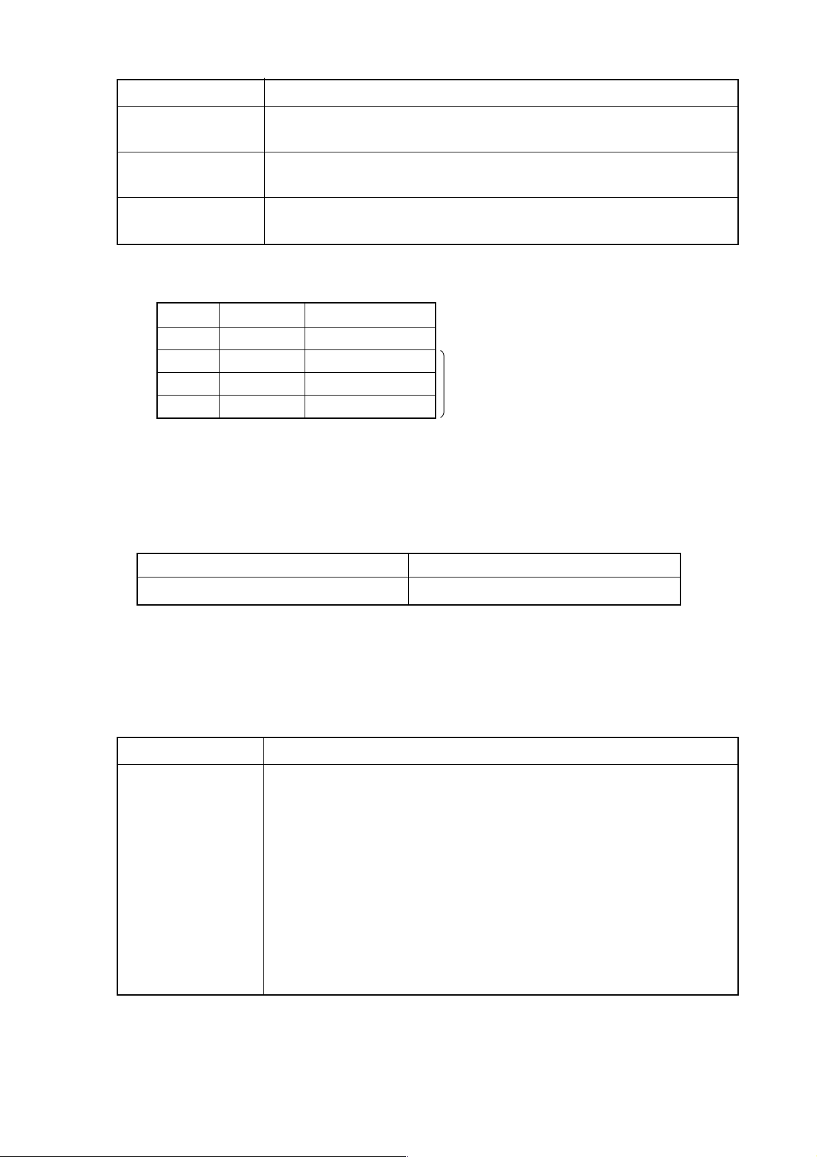
5.2 Replacing the Fuse for the Control Unit
[WARNING]
Prior to replacing the fuse, eliminate a cause for its blowing. Therefore, only the
qualified personnel fully trained for maintenance and safety is allowed for this work.
When you open the cabinet to replace the fuse, be careful not to touch a highvoltage circuit. If the cover is not in place and you touch inside, you will get an
electric shock.
5.2.1 Fuse Mounting Position
Back of Unit
Mother Board
5.2.2 Arrangement Specifications of Fuse
Basic Unit Arrangement Spec. Rating Individual Spec.
Σ 16/18/21 A02B-0236-K100 5A A60L-0001-0290#LM50
Fuse
1 - 58
Page 63

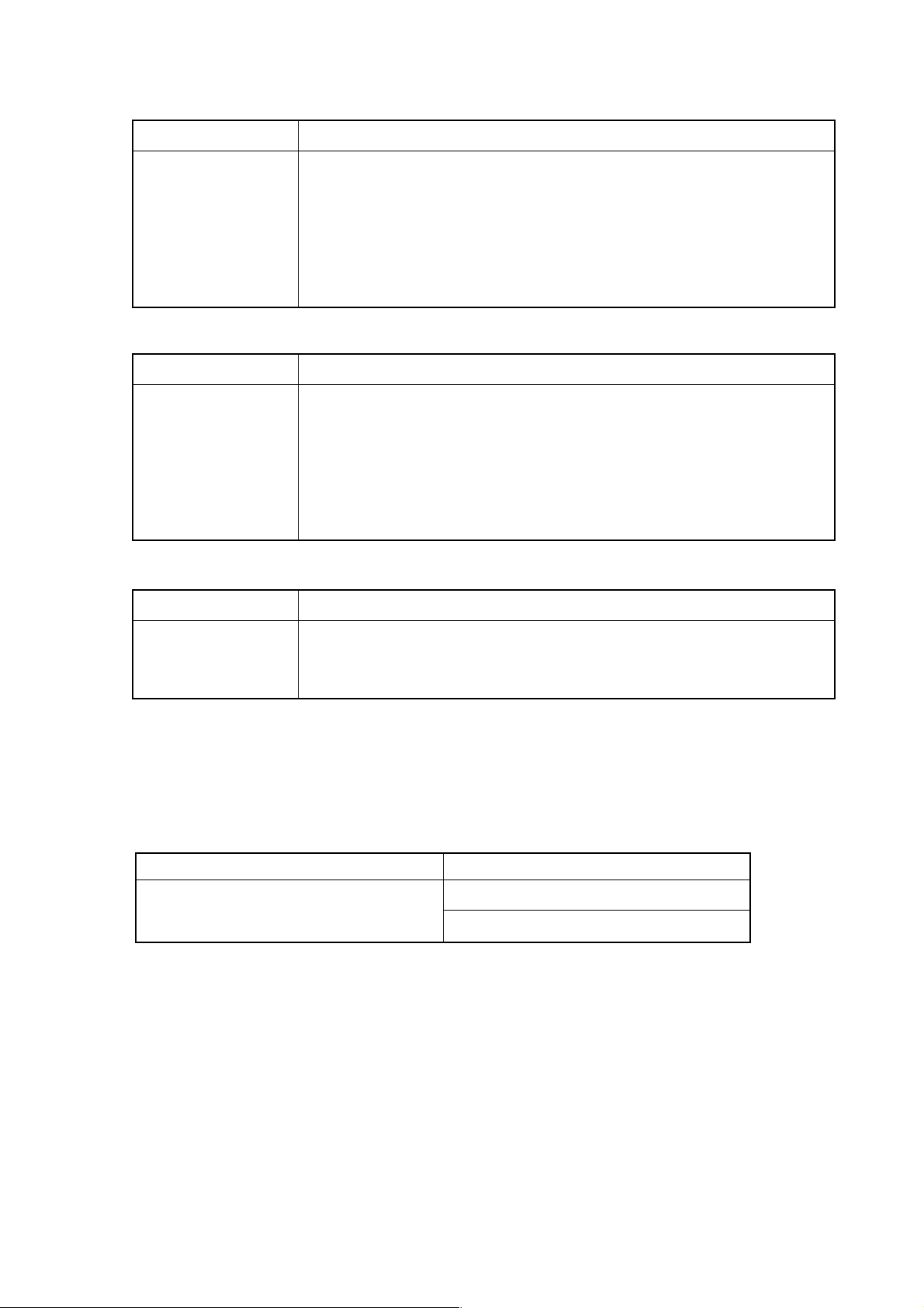
5.3 Replacing the Fan Motor
[WARNING]
When you open the cabinet to replace the fuse, be careful not to touch a high-
voltage circuit. If the cover is not in place and you touch inside, you will get an
electric shock.
5.3.1 Arrangement Specifications of Fan
For the unit with no option slots A90L-0001-0441 2 pieces
For the unit with 2 option slots A90L-0001-0423#105 2 pieces
For the unit with 4 option slots A90L-0001-0423#105 4 pieces
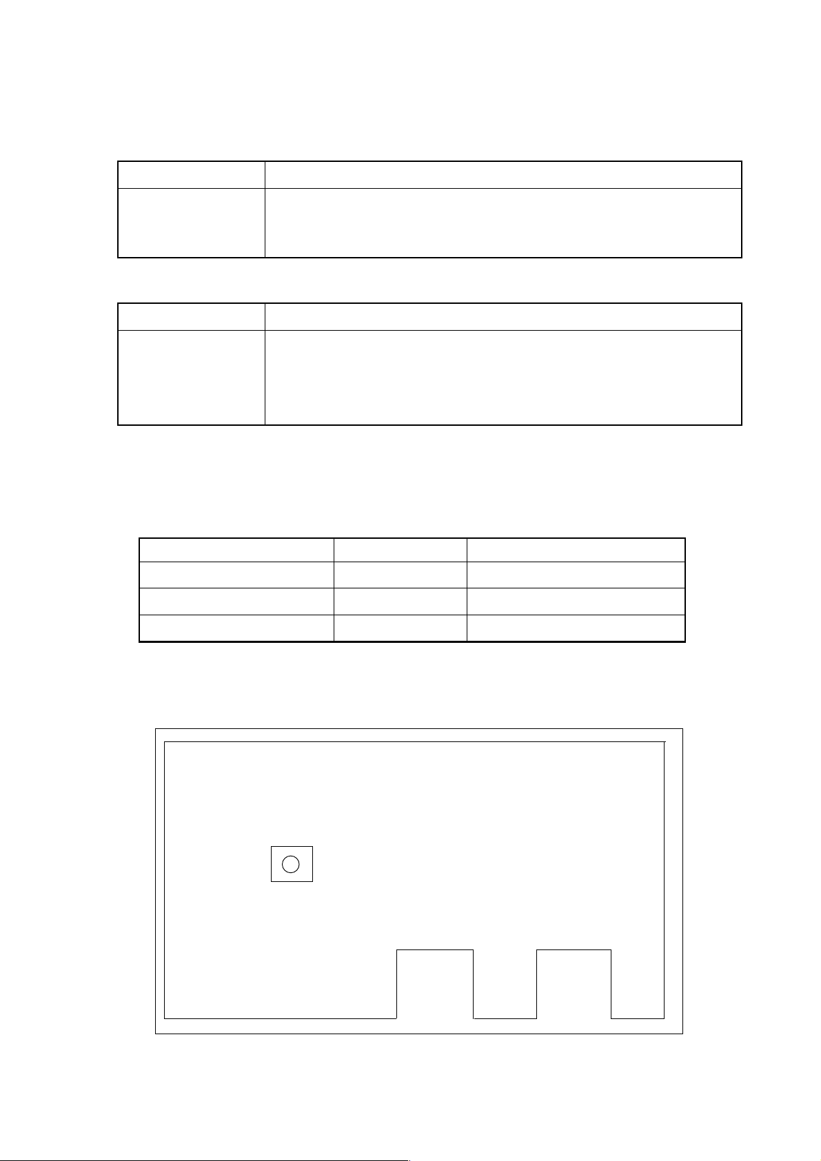
5.3.2 Replacing the Fan Motor
(1) When the unit is provided with no or two option slots
① When replacing the fan motor, be sure to turn off the power for the machine
(CNC).
Arrangement Spec. Required Q’ty
② Disconnect a connector from the fan motor you want to replace. The connector
is latched. Holding down the latch at the lower part of the connector with a
regular screwdriver, etc., pull it out.
③ Unlatch the fan motor and take it out.
④ Insert a new fan motor into a fan case and reconnect the connefctor.
Connector
Fan Motor
Fan Case
(Note) Pay attention to the fan motor’s direction so that the air flows from the bottom
to the top. (A label should face upward)
1 - 59
Page 64

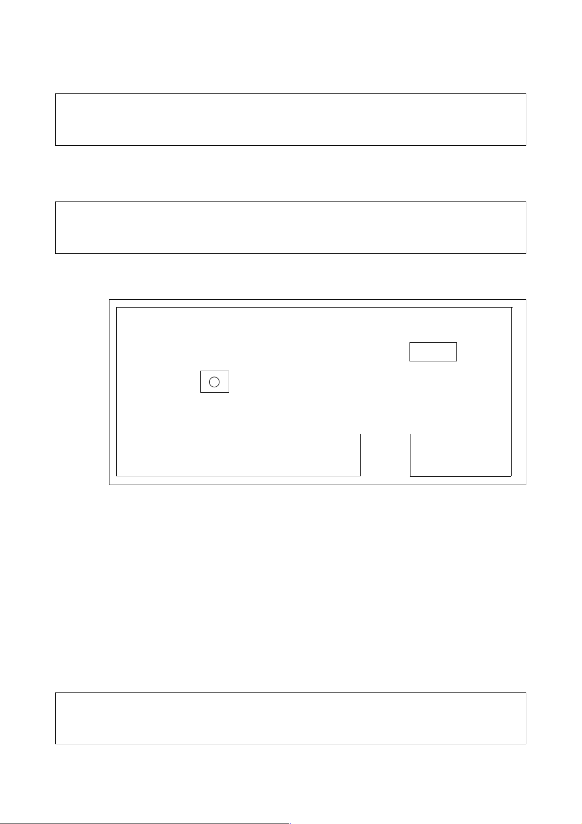
(2) When the unit is provided with four option slots
① When replacing the fan motor, be sure to turn off the power for the machine
(CNC).
② Disconnect a connector from the fan motor you want to replace. The connector
is latched. Holding down the latch at the lower part of the connector with a
regular screwdriver, etc., pull it out.
③ Unlatch the fan cover and take it out.
④ The fan motor is fixed to the fan cover. Unlatch and take out the fan motor.
⑤ Attach a new fan motor to the fan cover. Then, reattach the fan cover to the
unit and reconnect the connector.
Fan Cover
Connector
(Note) Pay attention to the fan motor’s direction so
that the air flows from the bottom to the top.
(A label should face upward)
Fan Motor
1 - 60
Page 65

5.4 Adjusting the Contrast of the Monochrome Display
When using the monochrome display, its contrast can be adjusted in the following manneIn
the OVERALL screen, operate the keys in the following sequence:
[OPRE/MAINTE] → [F4/SYSTEM] → [3] [0] (F MENU) [INPUT] → (F SETTING) [INPUT]
The SETTING(HANDY) screen will appear at the lower right of the screen.
(Note) When other SETTING screen than HANDY is being displayed, use the page
keys to dplay this screen.
Move the cursor to the CONTRAST item.
Press [F10/(OPRE)], followed by [F7/ON] or [F8/OFF] to adjust the contrast.S
SETTING(HANDY)
PARAMETER WRITE = 0 (0 : DISABLE 1: ENABLE)
~
contrast (+ = [ON:1] -= [OFF:0])
[ ] [ ] [ ] [ ] [ (OPRT) ]
↓
[ ] [ ON:1 ] [ OFF:0 ] [ ] [ ]
After adjustment, press [ALTER]. You will be returned to the F-MENU screen. In the
seen, press [RETURN] to return to the OVERALL screen.
1 - 61
Page 66

I-III RS-232C INTERFACE SPECIFICATION
1. CONNECTION INTERFACE
(1) For the Σ 10: Connectors (JD5A, JD5B) on the main CPU board
For the Σ 16/18: Connectors (JD36A, JD36B) on the motor board
[Connector type: PCR-EV20MDT]
(2) Junction Connector on Operator Panel
12345678910
RD 0V DR 0V CS 0V CD 0V
11 12 13 14 15 16 17 18 19 20
SD 0V ER 0V RS 0V
[Connector type: DBM-25S]
12345678910111213
FG SD RD RS CS DR SG CD
14 15 16 17 18 19 20 21 22 23 24 25
ER +24
2. DESCRIPTION OF SIGNALS
Signal I/O Description
FG Frame Ground
SD Output Send Data
RD Input Receive Data
RS Output Request to Send
When a control code is used: Turned to ON when transmission/reception is
initiated, and turned to OFF when it is terminated
When a control code is not used: Turned to ON when transmission/
reception is initiated. When this signal is turned to OFF, stop sending the
data within 10 characters because a buffer is full.
CS Input Clear to Send.
When this signal is turned to ON, the data is send out, regarding the other
mating device ready to receive. When turned to OFF, data-sending stops
within 2 characters.
DR Input Data Set Ready.
When this signal is turned to ON, the other mating device is regarded ready
to operate.
SG Signal Ground
CD Input Data Carrier Detect.
When this signal is turned to ON, the other mating device is regarded ready
to operate.
ER Output Data Terminal Ready.
When this signal is turned to ON, it means that the NC unit is ready to
operate. It is normally left turned to ON since power-on.
+24V
+24V
1 - 62
Page 67

3. TRANSMISSION METHOD
The RS-232C interface generally allows two kinds of transmission methods; synchronous
and start-stop. This system uses a start-stop method. In the start-stop method, start bits
precedes information bits, followed by parity and stop bits.
4. CONTROL CODES
Control codes can be used when transmitting/receiving from an external device. Use them
normally by the following setting.
Code Description Bit Pattern Hex. Parameter
DC1 Request to Send 00010001 11 PRM0112
DC2 Start to Send 00010010 12 PRM0113
DC3 Request to Stop Send 10010011 93 PRM0114
DC4 End to Send 00010100 14 PRM0115
5. TRANSMISSION
① When the control code is used
ER (Output)
RS (Output)
SD (Output)
CD (Input)
DC2 DC4
CS (Input)
RD (Input)
DC3 DC1
1 - 63
Page 68

② When the control code is not used
ER (Output)
RS (Output)
SD (Output)
CD (Input)
CS (Input)
RXD (Input)
6. RECEPTION
① When the control code is used
DC2
DC4
ER (Output)
RS (Output)
DC1
SD (Output)
CD (Input)
CS (Input)
RD (Input)
(Note) The DC3 code is not sent out according to setting.
DC1DC3
DC3
%
(Note)
1 - 64
Page 69

② When the control code is not used
ER (Output)
RS (Output)
SD (Output)
CD (Input)
CS (Input)
RD (Input)
%
7. INPUT/OUTPUT PORTS
This system uses the RS-232C as a standard interface and has one port ready for it. There
are device numbers ranging from 1 to 6. It is necessary to specify the port numbers in
setting specification for the device numbers.
Parameter No. Description
PRM0132 NC data input device number
PRM0133 NC data output device number
PRM0135 Custom macro external output device number
Device No. 1: RS-232C (Port number is PRM0124)
Device No. 2: Tape reader (Port number is PRM0125)
Device No. 3: Tape puncher (Port number is PRM0126)
Device No. 4: Card (Port number is PRM0127)
Device No. 5: Auxiliary-1 (Port number in PRM0128)
Device No. 6: Auxiliary-2 (Port number in PRM0129)
8. SETTING THE SPECIFICATION FOR THE DEVICE NUMBERS
Set the specification for the device numbers used. You can set the following for each device
number.
1. Parity bits
2. Data length
1 - 65
Page 70

3. Whether the control code is used
4. Stop bits
5. Baud rate
6. Port number used
Their respective corresponding parameters are as follows]
Device No. 1 (RS-232C): PRM0104, 0116, 0124
Device No. 2 (Tape reader): PRM0105, 0117, 0125
Device No. 3 (Tape puncher): PRM0106, 0118, 0126
Device No. 4 (Card): PRM0107, 0119, 0127
Device No. 5 (Auxiliary-1): PRM0108, 0120, 0128
Device No. 6 (Auxiliary-2): PRM0109, 0121, 0129
PRM0104
76543210
Setting of Device No. 1
EVP PRTY Parity Bit
0 0 None
0 1 Even number
1 0 None
1 1 Odd number
DLN Data Length
0 8 bits
1 7 bits
RSB Control Code
0 Used
1 Unused
EVP PRTY DLN RSB STP
STP Stop Bits
0 2 bits
1 1 bit
Likewise, PRM0105 through PRM0109 are used to set the data for the device no. 2
through no. 6.
PRM 01 16 Baud Rate
1 - 66
Page 71

Set Value Baud Rate
08 1200
11 2400
13 4800
15 9600
Others 4800
Likewise, PRM0117 through PRM0121 are used to set the baud rate for the device no. 2
through no. 6.
PRM0124 Port Number
1 ~ 2 RS232C1, 2
Others RS232C1
Likewise, PRM0125 through PRM0129 are used to set the port number for the device no. 2
through no. 6.
(Note) Two ports cannot be used simultaneously.
9. OTHER SETTINGS
The following settings are common to all, regardless of the device number.
PRM0100
76543210
NOST SPC ICR2 ICR1 EIA ISP CTV TVC
NOST Outputs a request to stop send (control code DC3) upon
completion of input
0Yes
1No
SPC Adds a space code before each address
0Yes
1No
ICR2 ICR1 Format to punch EOB by ISO code
0 0 LF • CR • CR
0 1 LF • CR
10LF
11LF
1 - 67
Page 72

EIA ISP Output Code Format
0 0 ISO
0 1 ASCII
1 0 EIA
1 1 EIA
Automatic distinction at input
CTV Counts characters to make a TV check during control-out
0Yes
1No
Meaningless when TVC is 0
CTV Makes a TV check
0No
1Yes
10. DATA FORMAT
% ; Significant Information %
Data end code
Program, parameter, etc.
Code distinction (used to distinguish a
code at input)
Data start code (skipped at input)
When punching multiple programs on one tape;
% ; One program ; One program • • • • • • • • %
Means a seam when inputting/outputting multiple programs
11. FEED LENGTH
A feed can be inserted before or after the significant information (from % to %) or in between
the NC programs when outputting multiple programs.
% ; Program ; Program ; Program
Feed between Programs (Space Code)
Feed at Output (Null Code)
PRM0138 Feed Length at Tape Output
PRM0139 Program Interval at Tape Output
1 - 68
Page 73

12. PARAMETER RELATED TO PROGRAM INPUT/OUTPUT
PRM3107
PRM3106
76543210
NE89
NE89 Prohibits editing (input/output) of the programs O8000 through
O9999
0Yes
1No
76543210
NXTO SM99 SM30 SM02 REP RDL
NXTO When the next O-number appears in registering a program
0 Prepares another file automaticlaly
1 Regards it as an end of the program
SM99 In registering a program, M99 is
0 Not regarded as an end of the program
1 Regarded as an end of the program
SM30 In registering a program, M30 is
0 Not regarded as an end of the program
1 Regarded as an end of the program
SM02 In registering a program, M02 is
0 Not regarded as an end of the program
1 Regarded as an end of the program
REP When you tried to register a program whose O-number is the
same as that of an already registered program
0 Results in an alarm
1 Registered after deleting the already registered one. When
editing of the already registered program is prohibited, an alarm
is issued without deleting it.
RDL When registering all the programs at once in the foreground
0 Registered after the already registered programs
1 Registered after deleting the already registered programs. The
programs whose editing is prohibited are not deleted.
1 - 69
Page 74

13. CABLE CONNECTION
CNC Unit External Device
FG (1) FG (1)
SD (2) SD (2)
RD (3) RD (3)
RS (4) RS (4)
CS (5) CS (5)
DR (6) DR (6)
SG (7) SG (7)
CD (8) CD (8)
ER (20) ER (20)
1 - 70
Page 75

II. ALARM LIST
1. Alarms Related to Program and Operation (Alarm No. 100 to No. 799)
(Alarm No. F000 to No. F299)
(Alarm No. 5000 to No. 5999)
2. Alarms Related to Absolute Pulse Coder (APC) (Alarm No. F300 to No. F309)
3. Alarms Related to Serial Pulse Coder (SPC) (Alarm No. F350 to No. F351)
4. Alarms Related to Servo (Alarm No. F400 to No. F421)
5. Alarms Related to Overtravel (Alarm No. F500 to No. 511)
6. Alarms Related to Overheat (Alarm No. F700 to No. F702)
7. Alarms Related to Direct Tap (Alarm No. F740 to No. F742)
8. Alarms Related to Serial Spindle (Alarm No. F749 to No. F774)
9. System Alarms (Alarm No. 900 to No. 999)
2 - 1
Page 76

1. Alarms Related to Program and Operation
100 (#△△△ ) G10 Command Error
[Description] A G10 command has an error.
A number indicating alarm details is displayed in parentheses.
#001: Short of a command
#002: Illegal command value
#003: There is an unnecessary command
#011: Parameter number error (N)
#012: Parameter axis number error (P)
#013: Parameter bit number error (Q)
#014: Parameter set value error (R)
#015: There is an unnecessary command
#016: A write disabled parameter has been specified
#061: P-command error
#062: R-command error
#063: Q-command error
#071: For the commands prior to Polygon mode, P or Q has not
been commanded.
#072: For the commands during Polygon mode, only one of P and Q
has been commanded.
#073: P command value is outside the range.
#074: Q command value is outside the range.
#075: R command value is outside the range.
#076: R command exists in Phase Control Invalid
(PRM7602, #5 (C0F) = 1).
#077: R command exists in Polygon by the servo motor.
[Remedy] Correct the program.
L80
L50
L110
101 (△△△△) Zero Point Return Incomplete
[Description] You specified an axis which has not been returned to the zero point. Up to
four alarmed axes are displayed in parentheses.
[Remedy] Return the axis to the zero point.
102 F-code Command Error
[Description] A F-code command has not been specified in cutting feed (G01, G02, G03, or
G32) or F0 has been specified.
[Remedy] Correct the program.
2 - 2
Page 77

103 (#△△△ ) Thread Cutting Command Error
[Description] A thread cutting command has an error.
A number indicating alarm details is displayed in parentheses.
#001: Three or more axes have been specified
#002: A start shift angle Q is beyond a specified range
(00 ≦ Q ≦ 3600)
[Remedy] Correct the program.
106 Plane Selection Command Error
[Description] A plane selection command (G17 to G19) has an error.
There are incorrect relations between the parameter no. 1023 (name of each
axis) and parameter no. 1024 (which axis each axis assumes in the basic
coordinate system). Or, you have specified a one of G17 to G19 commands
which do not determine the plane.
【Example】 G17 X Y A ; (The A-axis is parallel with the X-axis)
[Remedy] Correct the parameter or program.
[Caution] The plane disappears at reset time and is recreated at start time. When
starting from the reset state, therefore, this alarm may occur even if one of
G17 to G19 commands has not been specified.
107 Offset Number Error
[Description] A specified tool offset number exceeds the maximum number of tool offset
pairs.
[Remedy] Correct the program.
112 Tool Number Error
[Description] A specified tool number exceeds the maximum number of tool offset pairs.
[Remedy] Correct the program.
113 (#△△△ ) Polar Coordinate Interpolation Command Error
[Description] A polar coordinate interpolation command has an error.
A number indicating alarm details is displayed in parentheses.
#001: A G120/G121 command is not an independent block
#002: When G120/G121 was specified, it was not the tool diameter
compensation cancel mode (G40)
2 - 3
Page 78

#003: A work coordinate value of a linear axis was a minus value when G121
was specified, and G02/G03 was specified for the first move.
[Remedy] Correct the program.
114 (#△△△ ) Polar Coordinate Interpolation Mode Error
[Description] A wrong command was given in the polar coordinate interpolation mode.
A number indicating alarm details is displayed in parentheses.
#001: A disallowed G code has been specified.
#002: A T code has been specified (for the L-system only)
[Remedy] Correct the program.
115 Tool Diameter/Nose Radius Compensation Error
[Description] A G-code command other than G00/G01 was used to specify start-up or
cancellation of tool diameter/nose radius compensation.
[Remedy] Correct the program.
117 (#△△△ ) Tool Diameter/Nose Radius Compensation Interference Error
[Description] There was an excessive depth of cut in tool diameter/nose radius
compensation. (Interference error)
A number indicating alarm details is displayed in parentheses.
#001: Circular arc radius < Tool diameter compensation amount
#002: Other interference
[Remedy] Correct the program or tool diameter compensation amount.
118 Tool Diameter/Nose Radius Compensation Intersection Error
[Description] There is no intersection in tool diameter/nose radius compensation.
[Remedy] Correct the program or tool offset amount.
119 (#△△△ ) Tool Diameter/Nose Radius Compensation Mode Error
[Description] There was an erroneous command in the tool diameter/nose radius
compensation mode.
A number indicating alarm details is displayed in parentheses.
#001: Plane change in the current block
#002: Plane change in the next block
#003: Erroneous G-code in the current block
#004: Erroneous G-code in the next block
2 - 4
Page 79

#005: G38 command (holds an offset vector) other than G00/G01 in the
current block
#006: G38 command (changes an offset vector) other than G00/G01 in the
next block
#008: In-plane axis command (corner arc) by the G39 command in the next
block
[Remedy] Correct the program.
120 (#△△△ ) Tool Length Automatic Measurement Command Error
[Description] A tool length automatic measurement command has an error.
A number indicating alarm details is displayed in parentheses.
#001: Not G90
#002: Specified axis abnormal
#003: Measured length = 0
#004: Measured length > Measured speed length
#005: Measured distance < Measured speed length
[Remedy] Correct the program.
121 (#△△△ ) Tool Length Automatic Measurement Command Error
[Description] An H-code command has an error in tool length automatic measurement.
A number indicating alarm details is displayed in parentheses.
#001: An H-code has been specified in the G37 command block.
#002: No H-code has been specified before the G37 command block.
[Remedy] Correct the program.
123 Tool Length Automatic Measurement Operation Error
[Description] A measurement position arrival signal was not turned on in a measurement
range.
[Remedy] Correct the program or parameter.
124 (#△△△ ) Optional Angle Chamfering Corner R
[Description] An optional angle chamfering corner R command has an error.
A number indicating alarm details is displayed in parentheses.
#001: A ,C/ ,R command value is a minus value
#002: An identical block contains both ,C and ,R command
#003: The current block does not contain G01 through G03
#004: There is no axis move in the plane of the current block
#005: The current block contains an erroneous G-code
2 - 5
Page 80

#006: The next block does not contain G01 through G3
#007: There is no axis move in the plane of the next block
#008: The next block contains an erroneous G-code
#009: There is a plane change in the next block.
#010: An original stroke was exceeded in the current block.
#011: An original stroke was exceeded in the next block.
#012: Calculation error
[Remedy] Correct the program.
126 (#△△△ ) Cylindrical Interpolation Command Error
[Description] A cylindrical interpolation command has an error.
A number indicating alarm details is displayed in parentheses.
#001: There is no rotary axis command
#002: Not an independent command
#003: Illegal model G-code
[Remedy] Correct the program.
127 (#△△△ ) Cylindrical Interpolation Mode Error
[Description] There was an erroneous command during the cylindrical interpolation mode.
A number indicating alarm details is displayed in parentheses.
#001: Erroneous G-code command
#002: T-code command (L-system only)
#003: Rotary axis command by G00
#004: Cylindrical interpolation command during the mode
[Remedy] Correct the program.
128 G68 Error M
[Description] A G68 command format has an error or the plane was changed during the
G68 mode.
[Remedy] Correct the program.
130 (#△△△ ) Block Command Error
[Description] There is an error in a method to specify a block.
A number indicating alarm details is displayed in parentheses.
#001: A G251 command is not an independent block.
#100: An-M-code other than M30 was specified in the simple 2nd series
(feeder control) program.
#101: POUT/OUT command format error in the simple 2nd series (feeder
control) program. (No output numbers specified)
2 - 6
Page 81

#102: POUT/OUT command output number error in the simple 2nd series
(feeder control) program.
[Remedy] Correct the program.
131 Radius Designation on Arc Error
[Description] A circular arc radius has been specified, whose circular arc center position
cannot be calculated.
【Example】• A radius was specified with one-round circular arc
• A radius value is smaller than a length from a start point to an
end point
[Remedy] Correct the program.
132 (#△△△ ) Circular Arc Interpolation Error
[Description] A circular arc interpolation command has an error.
A number indicating alarm details is displayed in parentheses.
#001: The center has not been specified (I, J, K)
#002: The center has been specified (I, J, K), but its value is 0
#003: A difference in a radius value at the start and end points exceeds a
parameter set value.
[Remedy] Correct the program.
133 (#△△△ ) Canned Cycle Command Error
[Description] A canned cycle command for drilling has an error.
A number indicating alarm details is displayed in parentheses.
#000: A Z-point (hole bottom position) has not been specified in the first block
of the canned cycle for drilling
#001: Back boring (G87) has been specified in the R-point return mode.
#100: When specifying a shift amount by Q in back boring (G87) or fine
boring (M-system: G-76, L-system: G861) (parameter No. 5100, #2
(SIJ) = 0), the parameter no. 5127 has not been set (parameter for the
drilling axis = 0)
#101: When specifying a shift amount by Q in back boring (G87) or fine
boring (M-system: G76, L-system: G861) (parameter No. 5100, #2
(SIJ) = 0), the parameter no. 5127 has been illegally set (parameter for
the drilling axis = drilling axis)
[Remedy] Correct the program or parameter.
2 - 7
Page 82

134 (#△△△ ) Drilling Pattern Cycle Command Error
[Description] A drilling pattern cycle command has an error.
A number indicating alarm details is displayed in parentheses.
#000: L has not been specified or L = 0 has been specified
#001: I has not been specified by a G70 command
#002: When L is not equal to 1 in a G71 command, K or I has not been
specified.
#003: When L is equal to 1 in a G71 command, I has not been specified.
#004: I has not been specified by a G72 command
#005: A has not been specified by a G77 command or A = 0 has been
specified
#006: K, C, or I has not been specified by a G77 command.
#007: G70, G71, G72, or G77 has been specified in the G80 mode
[Remedy] Correct the program.
135 (#△△△ ) Circle Cutting Command Error
[Description] A circle cutting command has an error.
A number indicating alarm details is displayed in parentheses.
#002: No I-command (G302 to G305)
#003: No K-command (G304, G305)
#004: No U-command (G304, G305)
#005: I-command = 0 (G304, G305)
#006: K-command = 0 (G304, G305)
#007: U-command = 0 (G304, G305)
#008: Q-command = 0 (G302 to G305)
#009: Tool diameter ≧ | I-command | (G302 to G305)
#012: | R-command | > | I-command | (G302 to G305)
#013: | I-command | - | J-command | ≦ Tool diameter (G304, G305)
#014: | J-command | > | I-command | (G302 to G305)
#015: | U-command | > | K-command | (G304 to G305)
[Remedy] Correct the program.
136 (#△△△ ) Square Cutting Command Error
[Description] A square side external cutting/plane machining cycle command has an error.
2 - 8
Page 83

A number indicating alarm details is displayed in parentheses.
#002: No I-command (G322 to G326)
#003: No J-command (G322 to G326)
#004: No K-command (G322 to G305)
#006: No P-command (G322 to G326)
#007: No Q-command (G322 to G326)
#010: I-command = 0 (G324 to G326)
#011: J-command = 0 (G324 to G326)
#012: K-command = 0 (G324 to G326)
#013: Q-command = 0 (G324 to G326)
#014: I-command ≦ 0 (G322, G323)
#015: J-command ≦ 0 (G322, G323)
#017: P-command < 0 (G322, G323)
#018: A-command < 0 (G322, G323)
#019: C-command < 0 (G322, G323)
#020: C-command < | K-command | (G322, G323)
#021: A-command > | I-command/2 | (G322, G323)
#022: A-command > | J-command/2 | (G322, G323)
#023: | K-command | > | J-command | (G324 to G326)
#024: Finish allowance > | J-command | - | K-command | (G325, G326)
#025: C-command is not 1 to 4 (G325, G326)
[Remedy] Correct the program.
137 (#△△△ ) Pocket Cutting Command Error
[Description] A pocket cutting command has an error.
A number indicating alarm details is displayed in parentheses.
#009: No I-command (G327 to G333)
#010: No J-command (G328 to G332)
#011: No K-command (G327 to G333)
#012: No P-command (G330 to G332)
#013: No Q-command (G327 to G333)
#014: No A-command (G329, G332)
#015: No Z-command (G327, G328, G330, G331)
#017: I-command = 0 (G333)
#018: K-command = 0 (G327 to G332)
#019: Q-command = 0 (G327 to G332)
#021: J-command < 0 (G330)
#022: C-command < 0 (G329)
2 - 9
Page 84

#023: C-command ≦ 0 (332)
#024: P-command ≦ 0 (332)
#025: P-command < 0 (G330, G331)
#026: A-command - tool diameter ≦ 0 (G328)
A-command + tool diameter ≦ 0 (G331)
#027: | I-command | < tool diameter (G327)
#028: I-command < C-command (G333)
#029: I-command < | K-command | (G333)
#030: | I-command | < finish allowance (G327)
#031: [I-command/2] < tool diameter (G328)
#032: [I-command/2] < finish allowance (G328)
#033: [I-command/2] < [A command - tool diameter] (G328)
[I-command/2] < [A-command + tool diameter] (G331)
#035: | I-command | - | J-command | < |finish allowance x 2 | (G327)
#037: Finish allowance > [I-command - tool diameter] (G333)
#038: Tool diameter > [| I-command | - finish allowance] (G327)
#039: [(I-command/2) - finish allowance] < tool offset amount (G328)
#040: Tool diameter > [I-command - J-command - (finish allowance x 2)]
(G327)
#042: Tool diameter > [J-command/2] (G328)
#043: Finish allowance > [J-command/2] (G328)
#044: [A-command - tool diameter] > [J-command/2] (G328), [A-command +
tool diameter] > [J-command/2] (G331)
#045: Tool diameter > [(J-command/2) - finish allowance] (G328)
#046: Finish allowance > Q-command (G329, G332, G333)
#047: Finish allowance > K-command (G329, G332, G333)
#048: Finish allowance > C-command (G329, G332)
#049: C-command > | A-command | (G329)
#050: C-command < finish allowance (G328, G331)
#051: Tool diameter > [| A-command | - finish allowance] (G329)
#052: | R-command - Z-command | < finish allowance (G327, G328)
#053: Start radius < final radius (G330), Start width < final width (G331)
2 - 10
Page 85

#055: The left and right circuit arc centers of the track are the same (G329,
G332)
[Remedy] Correct the program.
138 (#△△△ ) Direct Tap Command Error
[Description] A direct tap command has an error.
A number indicating alarm details is displayed in parentheses.
#000: A Z-point (hole bottom position) has not been specified in the first
direct tap block
#001: S-command = 0
#002: F-command = 0
#005: Other canned cycle has been specified in the same block as a cancel
command (G80 or another G-code of Group 01)
#006: E-command = 0
#010: Direct tap has been specified in the thread cutting mode.
[Remedy] Correct the program.
139 Virtual Axis Command Error
[Description] Two or more virtual axes have been specified.
[Remedy] Correct the program.
140 (#△△△ ) Program Restart Error
[Description] Program restart operation has an error.
A number indicating alarm details is displayed in parentheses.
#001: It has not been reset when starting a restart block search (OP = 1)
#002: Pause signal (*SP) = 0 when starting a restart block search
#003: When an O-number was specified, there is no specified program when
starting a restart block search after calling that program
#004: When an O-number is not specified, the program you want to run has
not been called.
#005: Tool number error when starting a restart block search (L-system only)
#010: Restart signal (SRN) = 0 during a restart block search
#011: A restart block cannot be found (M02/M03 was detected)
#012: A restart block cannot be found (% was detected)
2 - 11
Page 86

#013: A restart block contains a T-command (Only for the L-system ATC
specification)
#020: A move completed axis was manually intervened when approaching a
restart position
[Remedy] Reset and redo restart operation.
142 (#△△△ ) Scaling Command Error
[Description] A G51 command format has an error.
A number indicating alarm details is displayed in parentheses.
#001: A G51 command is not an independent block
[Remedy] Correct the program.
143 Scaling Mode Error
[Description] An unavailable G-code has been specified during the scaling mode.
[Remedy] Correct the program.
144 G511/G501 Block Format Error
[Description] A G511/G501 command is not an independent block.
[Remedy] Correct the program.
146 G53 Error
[Description] An axis has been specified by incremental programming in machine
coordinate system selection (G53).
[Remedy] Correct the program.
149 Helical Cutting Command Error
[Description] Three or more linear axes have been specified.
[Remedy] Correct the program.
150 (#△△△ ) F15M Tape Format Error
[Description] The F15M tape format has an error. Displayed in parentheses is a number
representing alarm details.
#001: Work coordinate system offset number error
[Remedy] Correct the program.
151 (#△△△ ) i80M Tape Format Error
[Description] The i80M tape format has an error. Displayed in parentheses is a number
representing alarm details.
2 - 12
Page 87

#001: Work coordinate system offset number error
[Remedy] Correct the program.
158 (#△△△ ) Three Dimensional Tool Offset Error
[Description] A three dimensional tool offset command format has an error.
A number indicating alarm details is displayed in parentheses.
#001: There is a G-code which cannot be specified in the offset mode
#002: One of the basic axes, X, Y, and Z, does not exist.
[Remedy] Correct the program or parameter.
159 Three Dimensional Tool Offset Mode Error
[Description] There is no intersection in three dimensional tool offset.
[Remedy] Correct the program or tool offset amount.
160 (#△△△ ) Tool Length Compensation Error
[Description] A tool length compensation command has an error.
A number indicating alarm details is displayed in parentheses.
#001: A tool length compensation command block contains a G-code which
must not be specified.
#002: H has been independently specified n the G43/G44 mode, when tool
length compensation is applied to two axes.
#003: You are trying to apply tool length compensation to three or more axes.
#004: A tool length compensation axis cannot be determined in the G43/G44
command block.
[Remedy] Correct the program.
161 Tool Offset Error
[Description] Tool offset was specified for a circular arc (G02/G03).
[Remedy] Correct the program.
162 (#△△△ ) M-code Canned Cycle Error M
[Description] There is an error in a canned cycle command by an M-code.
A number indicating alarm details is displayed in parentheses.
<M06: ATC canned cycle>
#001: Canned cycle command in the canned cycle
#002: In normal directional control
#003: In tool diameter compensation
2 - 13
Page 88

#004: G-code command error
#005: Address command error
#006: Axis command error
#007: Parameter error
#008: The specified tool and the spindle tool are the same (Only for HS)
#009: Additional axis command error (Only for HG)
[Remedy] Correct the program.
163 (#△△△ ) Multiple M-code Command Error
[Description] There is an error in one-block multiple M-code commands.
#001: Multiple M-commands contain M00, M01, M02, or M30.
#002: Multiple M-code commands are disabled by parameter setting.
Parameter no. 3408 #7 (M3B) = 0
[Remedy] Correct the program.
175 (#△△△ ) Multiple Repetitive Cycle Error
[Description] A multiple repetitive cycle command has an error.
A number indicating alarm details is displayed in parentheses.
Take a remedy according to the following table.
No. Description Remedy
#?01 Finish profile blocks overflow
#?02 No finish profile
#?04 Bottom profiles overflow
#?05 Top profiles overflow
#?10 G71/G72 type-1 profile error
#?11 G71/G72 type-1 D-command error
#?20 G71/G72 cutting direction error
#?40 G74/G75 X, Z, U, or W command error
#?43 G74/G75 depth of cut error
#?44 G74/G75 I or K command error
Decrease the number of blocks.
Confirm a P/Q value/N-number. Decrease the number of
blocks.
Draw a profile;
Decimal point missing,
G01 missing after G02/G03,
X/Z moving direction error.
Confirm P/Q command value/N-number.
D0 command
The X-axis (G71)/Z (G72) does not move in the 1st block.
X-U same time: Z-W same time: No Z-W (G74)
X-U same time: No X-U: Z-W same time (G75)
The z-axis (G74)/X-axis (G75) does not move.
K0: I0 when the X-axis moves (G74)
I0: K0 when the Z-axis moves (G75)
2 - 14
Page 89

No. Description Remedy
#?60 G76 DH command error
#?62 G76 A-command error
#?63 G76 E-/F-command error
#?64 G76 X-, Z-, U-, or W-command error
#?65 G76 K-command error
#?70 Next block non-linear command error
#?71 Chamfering/corner R command error
#?72 Chamfering/corner R too large
#?73 Chamfering/corner R next block error
#?74 Angle designation linear interpolation error
#?75 A-command next block error
*
#?76 A-command next block calculation error
*
#?77 Optional angle chamfering too large
#?78 Optional angle chamfering/corner R
command error
#?79 Optional angle corner R too large
#?7A Radius designation on arc error
#?90 Cannot find an N-number (P) at the beginning
of the finish profile.
#?91 Cannot find an N-number (Q) at the end of
the finish profile.
#?92 Q was found before N-number P
#?93 No P-command
#?94 No Q-command
#?95 P-command = Q-command
#?96 A finish profile contains a forbidden G-
command.
#?97 The A-axis was used in a finish profile.
#?98 A macro statement was used in a finish
profile.
#?A0 G71/G72 type-2 profile error
#?A1 G71/G72 type-2 cut-down error
#?A2 G71/G72 type-2 depth of cut error
#?A3 G71/G72 chamfering error
#?A4 G71/G72 type-2 top shape error
#?A5 G71/G72 type-2 D-command error
#?C0 Profile table preparation error
%
#?C1 Tool nose radius calculation error
%
#?C2 G71/G72 type-1 depth of cut error
%
#?C4 G73 start error
%
#?C5 G76 depth of cut error
%
#?C6 G76 division by 0
%
#?C7 Infinite loop
%
#?OT T-command error
D ≦ 0, H ≦ 0, No DH
Beyond the A-range (Confirm a decimal point)
E0, No EF
X or Z stroke = 0, X stroke < K
K ≦ 0, K < finish allowance
Other than G01 in the block next to chamfering/corner R
Confirm the direction of an I-/J-/R-command
Confirm a profile. Decrease I, K, or R.
Confirm the direction of an I-, J-, or R command.
No X or Y
Confirm related parameters.
Confirm related parameters.
Confirm a profile. Decrease C.
Other than G01 in the ,C or ,R block. ,C and ,R same time
Confirm a profile. Decrease R.
Increase R (decimal point missing).
Confirm a profile (end point position command error)
Confirm P/Q command value/N-number.
Specify P.
Specify Q.
Change a P-/Q-command value.
Confirm a G-command.
Eliminate an A-command.
Eliminate a macro statement.
Draw a profile; Decimal point missing, G01 missing after
G02/G03, Z (G71) / X (G72) moving direction error.
Confirm P-/Q-command value/N-number.
Draw a profile. An error may be prevented by slightly
altering a depth of cut (D).
There is a point higher than a start point.
D0 command
Change a profile slightly.
No. 6202, #6 ← 0
Alter a D-command value slightly.
Alter a D-command slightly.
Alter a D-/K-command value slightly.
Alter a screw length/I-command value slightly.
Alter a profile slightly.
Eliminate a T-command (cannot be given)
[Cautions] ① The symbol “?” in the No. column is replaced by a number ranging from 0 to 6. (0:G70, 2:G73, ...,
6:G76)
② The alarms marked with “*” do not occur in normal setting. If they do, check the set values of related
parameters.
③ The alarms marked with “%” derive from NC internal calculations and normally do not occur. If they
occur, let us know an alarm number, message, alarmed program, and related parameters.
2 - 15
Page 90

176 (#△△△ ) Canned Cycle Error L
[Description] A canned cycle command has an error.
A number indicating alarm details is displayed in parentheses.
#001: Axis command error.
• Two axes within the plane have not been specified in the G90, G92,
or G94 command block.
• A non-plane axis command has been given during the canned cycle
mode.
#002: As an I, J, or K value is incorrect, a moving direction at approach
opposes to an original moving direction.
#004: A plane selection command (G17 to G19) has been given in a block
other than the G90, G92, or G94 command block during the canned
cycle mode.
[Remedy] Correct the program.
177 (#△△△ ) Angle Designation Linear Interpolation Error L
[Description] An angle designation linear interpolation command has an error.
A number indicating alarm details is displayed in parentheses.
#001: An angle A is other than -3600 to 3600.
#002: An original moving direction opposes to a moving direction after
calculation.
[Remedy] Correct the program.
178 (#△△△ ) Chamfering, Corner R Error L
[Description] An angle designation linear interpolation command has an error.
A number indicating alarm details is displayed in parentheses.
#001: In the 1st block, a value of I, J, or K exceeds an original stroke.
#002: The 2nd block does not contain G01.
#003: The 2nd block contains one of G17 to G19 commands.
#004: The 2nd block does not contain a command which works
perpendicularly to the 1st block.
#005: The 2nd block contains a G-command of Group 00 other than G09,
G141, and G142.
#006: In the 2nd block, a value of I, J, or K exceeds an original stroke.
[Remedy] Correct the program.
2 - 16
Page 91

179 (#△△△ ) Groove Width Offset Error L
[Description] A groove width offset command has an error.
A number indicating alarm details is displayed in parentheses.
#001: There is an axis command in one of the G150 through G152 command
blocks.
#002: Plane change during offset
#003: A tool nose point is not 1 to 4.
[Remedy] Correct the program or tool nose point.
180 G41/G42 Command Disabled L
[Description] G41 or G42 was specified during the G140/G143 mode.
[Remedy] Correct the program.
182 (#△△△ ) T-command error L
[Description] A T-command has an error.
A number indicating alarm details is displayed in parentheses.
#001: Digits error
#002: Turret number error
#003: Tool number error
#004: Offset number error
#005: Composite offset error (Tool nose radius ≠ 0 at tool nose point = 0)
#006: T9XXXXX ERROR (In ATC spec., Turret number = 90, 91, 99
command is erroneous.
#007: Composite offset start-up/cancel error (Axis command in the G02/G03
mode)
#008: Composite offset error (In composite offset, a turret number or tool
number changed for the preceding T-code.)
#009: Composite offset error (In composite offset, G52 has been specified in
the same block.)
[Only when the ATC is not attached]
#050: T-command execution disable signal from the machine side (‘TFDS’
:RG41, #6 ) = 1
[Only when the ATC is attached]
#100: No commanded tool (ALM2)
#101: Check error by each commanded tool type (ALM3)
#102: Arm tool provided on the tool rest side (ALM1)
#103: No empty pot on the magazine side (ALM2)
#104: No empty plane on the tool rest side (ALM2)
2 - 17
Page 92

#105: ATC command to a stationary tool (ALM3)
#106: No dummy tool on the magazine in MG-TP-TP operation. (ALM2)
#107: G159 command error
#108: Axial command given in a same block with T command except in
composite offset.
[Remedy] Correct the program or tool offset amount.
183 (#△△△ ) G128 Error L
[Description] A G128 command has an error.
A number indicating alarm details is displayed in parentheses.
#001: Not G01 for G98
#002: Axis command error (Be sure to specify two axes, linear axis and
rotary axis; the rest cannot be specified)
#003: An error related to the start and end point positions of a linear axis
[Remedy] Correct the program.
184 Back Machining Command Error L
[Description] The front/back machining mode was changed in the constant surface speed
control mode (G96/G196).
[Remedy] Correct the program.
186 (#△△△ ) WORKPIECE COOD. PRESET ERROR M
[Description] An error has occurred concerning presetting of the work coordinate system.
・Work coordinate system presetting could not be executed on completion of
manual zero point return following supply of power because of
presence of a pre-read block.
・An axis not yet subject to work coordinate system presetting has been
commanded in Auto run.
[Remedy] Preset the work coordinate system by performing manual zero point return
one more time after resetting.
188 No Write-to Option L
[Description] A G10 command was used to set the data for an unprovided optional function.
[Remedy] Correct the program.
2 - 18
Page 93

189 (△△△△ ) Parameter Setting Error
[Description] Parameter setting related to each function has an error.
A function name is displayed in parentheses.
G121: Parameter no. 3418, no. 3419, and no. 1024
G271: Parameter no. 3426, no. 3427, and no. 1024
G128: Parameter no. 3418 and no. 3419
PRST: Program restart approach order, Parameter no. 8703
[Remedy] Correct the program.
191 (△△△△ ) Option Command
[Description] No option has been added for a specified command.
A G-code indicating a function is displayed in parentheses.
The following lists exceptions
G01A: Angle designation linear interpolatio
G10P: Programmable parameter input
G80N: Canned cycle for drilling
DTAP: Direct tap
HRCL: Helical interpolation
SFTQ: Multiple thread cutting
,C ,R: Optional angle chamfering corner R
BKCD: Back coordinate system (L-system only)
3OFS: Three dimensional tool offset (M-system only)
HPCC: High-precision contour control (M-system only)
ETWC: Additional work coordinate system (M-system only)
[Remedy] Correct the program or add an option.
196 (#△△△ ) Cannot run reversely any more 【WARNING】 M
[Description] While running reversely by a retrace function, the machine cannot run
reversely any more.
A number indicating details is displayed in parentheses.
#001: There is a command disallowing a reverse run.
#002: There is no retraceable memory block.
[Remedy] Turning off the Retrace switch makes a warning message disappear and
changes over to forward run.
198 (#△△△ ) Program End
[Description] “%” was read in other than MDI operation.
[Remedy] When “%” was read, processing on the NC unit side is determined as follows,
depending on the parameter no. 3005, #3 (PEND).
2 - 19
Page 94

PEND = 0: The NC unit applies a reset to search for the head of the
program. PEND = 1: An alarm results
Alter the parameter or correct the program.
201 (#△△△ ) G25/G26 Command Error
[Description] A G25 or G26 command has an error. A number is displayed in the
parentheses, which represents alarm details.
#001: Not an independent block command.
#002: The P-data beyond the G26 command range has been specified.
#003: The Q-data beyond the G26 command range has been specified.
#004: The R-data beyond the G26 command range has been specified.
[Remedy] Correct the program.
203 (#△△△ ) WHEEL CUT: RESTART ERROR L
[Description] Operation of the Process Restart function is erroneous.
A number indicating the alarm details is displayed in parentheses.
#001: No reset state is available on starting of Restart Block Search. (‘OP’ =
1)
#002: Halt signal (‘*SP’) = 0 on starting of Restart Block Search.
#003: Either a program No. or a sequence No. is equal to 0 for the restarting
block.
#004: A program to be executed has not been called on starting of Restart
Block Search.
#005: Either a turret No. or a tool No. is equal to 0 on starting of Restart
Block Search.
#010: The program restarting signal (‘SRN’) has become “0” while in Restart
Block Search.
#011: The restart block cannot be found. (M02/M30/% are detected.)
#020: Although the program restarting signal has been turned OFF once on
completion of Restart Block Search, the program restarting signal has
been turned ON again before process restarting function is ended.
#030: Mode has been changed while in process restarting function. (Set to
one other than Memory mode.)
2 - 20
Page 95

#031: The order of approach axes (PRM8703) to the restart position has
been erroneously set. (Check only axes subject to shifting.)
204 WHEEL CUT:TURN OFF RESTART SIG. [WARNING] L
[Remedy] After turning OFF the program restarting signal, start Auto run.
209 (#△△△ ) Manual Coordinate System Setting Error L
[Description] There is an error in manual coordinate system setting.
Displayed in parentheses is a number representing the alarm details.
#001: Turret head clamp signal = 0
#002: The face number of the turret head informed from the machine side
differs from the one recognized by the NC unit.
210 (#△△△ ) Oscillation Command Error M
[Description] An oscillation command has an error.
A number indicating alarm details is displayed in parentheses.
#000: Other G-code has been specified in the G113 command block.
#001: An illegal address has been specified in the G113 command block.
#002: There is no U-command in the G113 command block.
#003: In a G113 command, a feed rate E is 0.
#004: G113 was specified during the canned cycle mode.
#020: Other G-code has been specified in the G114 command block.
#021: An illegal address has been specified in the G114 command block
[Remedy] Correct the program.
211 (#△△△ ) Oscillation Mode Error M
[Description] A command in the oscillation mode or operation has an error.
A number indicating alarm details is displayed in parentheses.
#010: A plane changed during the oscillation mode.
#011: A canned cycle was specified during the oscillation mode.
2 - 21
Page 96

#012: An oscillation axis was specified during the oscillation mode.
#013: G113 was specified again during the oscillation mode.
#014: One of G322 through G333 was specified during the oscillation mode.
#030: Machine lock was turning on/off during the oscillation mode.
[Remedy] Correct the program. Or, do not change the machine lock state during the
oscillation mode.
212 Safety Guard Tool Length Measurement Error M
[Description] There is an error in the tool length measurement method.
• Tool length was measured at too slow a speed for measurement.
• Tool length was measured with two or more simultaneous controllable axes.
[Remedy] Redo from the beginning.
213 (#△△△ ) Safety Guard Tool Length Operation Error M
[Description] There is an error in the safety guard tool length operation method. Displayed in
parentheses is a number representing alarm details.
#001: A tool length signal” was turned on in other than the reset mode (OP
= 1).
#002: The “tool length signal” was turned off before a reset (M02, M30, Reset
key) is applied after starting tool length measurement.
#003: Measurement was made with two or more simultaneous controllable
axes.
#004: The horizontal spindle head is attached when starting tool length
measurement for the 5-face machining equipment. Or, the horizontal
spindle head was attached during measurement.
#005: The JOG or HANDLE mode switch was pressed.
[Remedy] ① Redo from the beginning.
② The horizontal spindle head for the 5-face machining equipment is not
available.
2 - 22
Page 97

214 (#△△△ ) Safety Guard Comparison Operation Error M
[Description] There is an error in the safety guard comparison method. Displayed in
parentheses in a number representing alarm details.
#001: A “comparison signal” was turned on in other than the reset mode (OP
= 1).
#002: The “comparison signal” was turned off before a reset (M02, M03,
Reset key) is applied after starting comparison.
#003: Measurement was made with two or more simultaneous controllable
axes.
#004: The horizontal spindle head is attached when starting comparison and
measurement for the 5-face machining equipment. Or, the horizontal
spindle head was attached during measurement.
#005: The JOG or HANDLE mode switch was pressed.
[Remedy] ① Redo from the beginning.
② The horizontal spindle head for the 5-face machining equipment is not
available.
215 Safety Guard Comparison Interference Error [Warning] M
[Description] A tool entered the interference area in safety guard comparison.
[Remedy] Correct the program and redo from the begging. Or, apply a “start” as it is. Since
a warning message disappears and operation continues, it is also possible to
check all the warning-indicated parts and correct the program.
216 Safety Guard Command Error M
[Description] The horizontal spindle head is being called in safety guard (comparison)
operation for the 5-face machining equipment. (The horizontal spindle head in
not available)
[Remedy] Do not perform safety guard (comparison) operation in the program which
calls the horizontal spindle.
218 (#△△△ ) POLYGON COMMAND ERROR L
[Description] Illegal command in the Polygon turning.
A number indicating the alarm details is displayed in parentheses.
#001: M code for starting or ending Polygon turning.
2 - 23
Page 98

#002: A Polygon turn ratio has not been commanded before start of Polygon
turning.
[Remedy] Correct the program.
220 (#△△△ ) Trochoid Cycle Command Error M
[Description] There is an error in a trochoid cycle command. Displayed in parentheses is a
number representing alarm details.
#001: I-command = J-command = 0
#002: No K-command, or K-command ≦ 0
#003: No A-command, or A-command = 0
#004: | A-command | < K-command
#005: |
A-command | ≦ Tool diameter
#006: No C-command, or neither C = 2 or 3
#007: W-command < A x 2
#008: The central position of the arc groove cannot be calculated.
#009: The machining starting position cannot be calculated.
#010: P-command < 0
#011: Q-command < 0
[Remedy] Correct the program.
221 (#△△△ ) Helical Drilling Cycle Command Error M
[Description] There is an error in a helical drilling cycle command.
Displayed in parentheses is a number representing alarm details.
#000: No Z-command
#001: No I-command, or I-command = 0
#002: J-command ≦ 0
#003: I-command ≦ Tool diameter
#004: J-command ≦ Tool diameter
#005: No Q-command, or Q-command = 0
#006: The ,R-point is incorrect.
#007: The K-point is incorrect.
#008: Calculation error
#009: Concal cutting error
[Remedy] Correct the program.
222 (#△△△ ) High-speed Side Cutting Cycle Command Error M
[Description] There is an error in the high-speed side cutting cycle command.
Displayed in parenthese is a number representing the alarm details.
2 - 24
Page 99

#001: No Z-command
#002: No I-command, or I-command = 0
#003: No J-command, or J-command = 0
#004: No K-command, or K-command = 0
#005: No P-command
#006: No C-command, or C-command is not equal to 1 to 4
[Remedy] Correct the program.
223 (#△△△ ) z-feed Grooving Cycle Command Error M
[Description] There is an error in the z-feed grooving cycle command.
Displayed in parrentheses is a number representing the alarm details.
#001: No Z-command
#002: I-command = 0, and J-command = 0
#003: A-command = 0, and Q-command = 0
[Remedy] Correct the program.
224 (#△△△ ) Corner Pocketing Cycle Command Error M
[Description] There is an error in the corner pocketing cycle command.
Displayed in parentheses is a number representing the alarm details.
#001: No Z-command
#002: No I-command, or I-command = 0
#003: | I-command | ≦J-command
#004: | I-command | ≦Tool diameter
#005: J-command < Tool diameter
#006: No K-command, or K-command ≦0
#007: No C-command, or C-command is not equal to 1 to 4
[Remedy] Correct the program.
225 (#△△△ ) Square Pocketing Cycle Command Error M
[Description] There is an error in the square pocketing cycle command.
Displayed in parentheses is a number representing the alarm details.
#001: No Z-command
#002: No I-command, or I-command = 0
#003: | I-command | ≦Tool diameter x 2
#004: No J-command, or J-command = 0
2 - 25
Page 100

#005: J-command ≦ Tool diameter x 2
#006: No-K-command, or K-command ≦0
#007: A-command ≦Tool diameter
[Remedy] Correct the program.
260 (△△△△)HPCC Command Error M
[Description] There is an error in the high-precision contour control start or end block.
A character indicating alarm details is displayed in parentheses.
#001: Not an independent block
SMIR: In setting mirror image
G△△△ : Erroneous model G-code at start
[Remedy] Correct the program.
261 HPCC Mode Error M
[Description] In the high-precision contour control mode, a command has an error.
[Remedy] Correct the program.
262 Precontrol Command Error M
[Description] There is an error in the precontrol start or end block.
[Remedy] Correct the program.
263 Precontrol Mode Error M
[Description] There is a command error in the precontrol mode.
[Remedy] Correct the program.
270 (#△△△ ) Soft Jaw Forming Error L
[Description] There is an error in a soft jaw forming set value. A number is displayed in the
parentheses, which represents alarm details.
2 - 26
 Loading...