

Page 1
Impact Wrench
Llave de impacto
日立牌電動衝擊扳手
WR 22SA
HANDLING INSTRUCTIONS
INSTRUCCIONES DE MANEJO
使用說明書
Read through carefully and understand these instructions before use.
Leer cuidadosamente y comprender estas instrucciones antes del uso.
使用前務請詳加閱讀
Page 2

1 2
1
3
2
4
5
3
6
7
8
9
5
34
0
kg-m N·m
80
70
60
C
50
40 400
30 300
0
M22 × 70 (F 10T)
800
700
600
500
0
0
A
246810
B
(s)
1
Page 3

English Español
1
Pin, O-Ring type
2
Pin
3
Hex. socket
4
Ring
5
Anvil
6
Plunger type
7 Hole
8
Plunger
9
Spring
0
Switch
A
Rating
B Tightening time
C
Tightening torque
Pasador, junta tórica
Pssador
Receptàculo hexagonal
Anillo
Yunque
Tipo émbolo
Orificio
Embolo
Resorte
Interruptor
Potencia nomial
Tiempo de apriete
Trosión de apriete
中國語
錨釘 O 型環式
插銷
六角套筒
套環
鐵砧
活塞式
孔
柱塞
彈簧
開關
額定
旋緊時間
旋緊轉矩
2
Page 4

English
GENERAL SAFETY RULES
WARNING!
Read all instructions
Failure to follow all instructions listed below may result in
electric shock, fire and/or serious injury.
The term “power tool” in all of the warnings listed below
refers to your mains operated (corded) power tool or battery
operated (cordless) power tool.
SAVE THESE INSTRUCTIONS
1) Work area
a) Keep work area clean and well lit.
Cluttered and dark areas invite accidents.
b) Do not operate power tools in explosive
atmospheres, such as in the presence of flammable
liquids, gases or dust.
Power tools create sparks which may ignite the
dust of fumes.
c) Keep children and bystanders away while operating
a power tool.
Distractions can cause you to lose control.
2) Electrical safety
a) Power tool plugs must match the outlet.
Never modify the plug in any way.
Do not use any adapter plugs with earthed
(grounded) power tools.
Unmodified plugs and matching outlets will reduce
risk of electric shock.
b) Avoid body contact with earthed or grounded
surfaces such as pipes, radiators, ranges and
refrigerators.
There is an increased risk of electric shock if your
body is earthed or grounded.
c) Do not expose power tools to rain or wet
conditions.
Water entering a power tool will increase the risk
of electric shock.
d) Do not abuse the cord. Never use the cord for
carrying, pulling or unplugging the power tool.
Keep cord away from heat, oil, sharp edges or
moving parts.
Damaged or entangled cords increase the risk of
electric shock.
e) When operating a power tool outdoors, use an
extension cord suitable for outdoor use.
Use of a cord suitable for outdoor use reduces
the risk of electric shock
3) Personal safety
a) Stay alert, watch what you are doing and use
common sense when operating a power tool.
Do not use a power tool while you are tired or
under the influence of drugs, alcohol or medication.
A moment of inattention while operating power
tools may result in serious personal injury.
b) Use safety equipment. Always wear eye protection.
Safety equipment such as dust mask, non-skid
safety shoes, hard hat, or hearing protection used
for appropriate conditions will reduce personal
injuries.
c) Avoid accidental starting. Ensure the switch is in
the off position before plugging in.
Carrying power tools with your finger on the
switch or plugging in power tools that have the
switch on invites accidents.
d) Remove any adjusting key or wrench before
turning the power tool on.
A wrench or a key left attached to a rotating part
of the power tool may result in personal injury.
e) Do not overreach. Keep proper footing and balance
at all times.
This enables better control of the power tool in
unexpected situations.
f) Dress properly. Do not wear loose clothing or
jewellery. Keep your hair, clothing and gloves
away from moving parts.
Loose clothes, jewellery or long hair can be caught
in moving parts.
g) If devices are provided for the connection of dust
extraction and collection facilities, ensure these
are connected and properly used.
Use of these devices can reduce dust related hazards.
4) Power tool use and care
a) Do not force the power tool. Use the correct
power tool for your application.
The correct power tool will do the job better and
safer at the rate for which it was designed.
b) Do not use the power tool if the switch does not
turn it on and off.
Any power tool that cannot be controlled with the
switch is dangerous and must be repaired.
c) Disconnect the plug from the power source before
making any adjustments, changing accessories, or
storing power tools.
Such preventive safety measures reduce the risk
of starting the power tool accidentally.
d) Store idle power tools out of the reach of children
and do not allow persons unfamiliar with the
power tool or these instructions to operate the
power tool.
Power tools are dangerous in the hands of
untrained users.
e) Maintain power tools. Check for misalignment or
binding of moving parts, breakage of parts and
any other condition that may affect the power
tools operation.
If damaged, have the power tool repaired before
use.
Many accidents are caused by poorly maintained
power tools.
f) Keep cutting tools sharp and clean.
Properly maintained cutting tools with sharp cutting
edges are less likely to bind and are easier to
control.
g) Use the power tool, accessories and tool bits etc.,
in accordance with these instructions and in the
manner intended for the particular type of power
tool, taking into account the working conditions
and the work to be performed.
Use of the power tool for operations different from
intended could result in a hazardous situation.
5) Service
a) Have your power tool serviced by a qualified repair
person using only identical replacement parts.
This will ensure that the safety of the power tool
is maintained.
PRECAUTION
Keep children and infirm persons away.
When not in use, tools should be stored out of reach of
children and infirm persons.
3
Page 5

English
S
D
B
E
L
PRECAUTIONS ON USING IMPACT WRENCH
1. When using the tool at a hight, make sure that there
is nobody below.
2. Use earplugs if using for a long time use.
3. Switch the reversing switch only after the motor
has stoped when it is necessary to change the
direction of the rotation.
4. Use a step up transformer when a long extension
cable is used.
5. Confirm the tightening torque by a torque wrench
before use in order to assertain the correct tightening
torque to be used.
6. Assemble the socket securely to the impact wrench
with the socket pin and ring.
7. Confirm whether the socket has any cracks in it.
8. Always hold the body and side handles of the
impact wrench firmly. Otherwise the counterforce
produced may result in inaccurate and even
dangerous operation.
SPECIFICATIONS
Voltage (by areas)* (110V, 115V, 120V, 127V, 220V, 230V, 240V)
Power input* 850 W
No load speed 1800 / min
Capacities (size of bolts)
Tightening torque** Maximum 610N·m (62.2 kg-m)
Angle drive 19 mm
Weight (without cord) 4.8 kg
*Be sure to check the nameplate on product as it is subject to change by areas.
**Tightening the bolt without extension cord at rated voltage.
STANDARD ACCESSORIES
(1) Side handle ............................................................... 1
(2) Case ........................................................................... 1
Standard accessories are subject to change without notice.
M16 - M22 (High tension bolt)
M14 - M24 (Ordinary bolt)
OPTIONAL ACCESSORIES
(sold separately)
1. Variety of sockets
Although the Hitachi Impact Wrench is delivered
with only one standard socket, ample sockets are
available to cover impact tightening of various sizes
and types of bolts.
Table 1 B = 19 mm
Ordinary Socket Long Socket
Dimension (mm) Dimension (mm)
D
32
38
40
42
43
45
47
50
52
55
E
32
29
29
29
29
29
29
29
29
29
L
60
55
55
55
55
55
55
55
55
55
S
23
24
26
27
29
30
32
35
36
D
33
34
38
39
42
43
46
52
55
E
32
32
57
57
57
57
72
72
72
L
60
60
85
85
85
85
100
100
100
Designation
Hex. Socket 22
4
Socket
S
22
23
24
26
27
29
30
32
35
36
23
24
26
27
29
30
32
35
36
Page 6
English
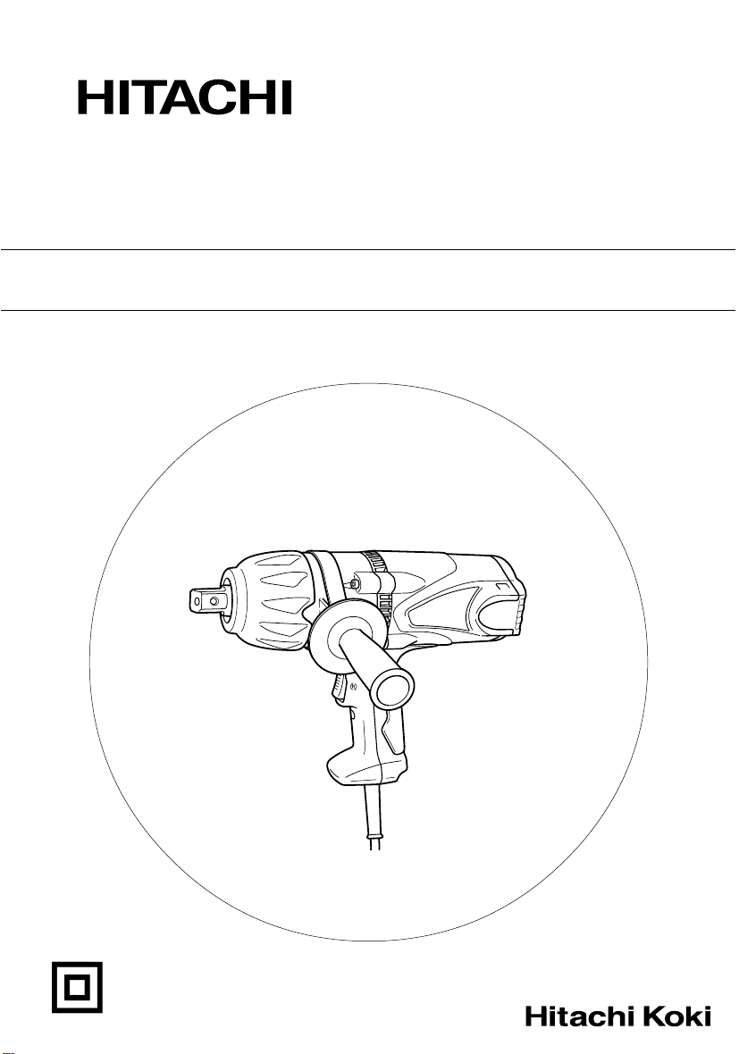
2. Extension bar
The extension bar is convenient for working in very
restricted spaces or when the socket provided cannot
reach the bolt to be tightened.
CAUTION
When the extension bar is used the tightening torque
is reduced slightly compared with the ordinary
socket. So it is necessary to operate the tool a little
longer to get the same torque.
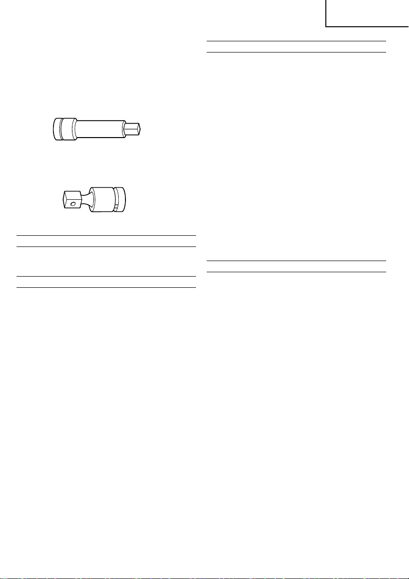
3. Universal joint
The universal joint is convenient for impacting nuts
when there is an angle between the socket and
wrench, or when working in a very narrow space.
Optional accessories are subject to change without notice.
APPLICATIONS
䡬 Tightening and loosening various kinds of bolt and
nut.
PRIOR TO OPERATION
1. Power source
Ensure that the power source to be utilized conforms
to the power requirements specified on the product
nameplate.
2. Power switch
Ensure that the power switch is in the OFF position.
If the plug is connected to a receptacle while the
power switch is in the ON position, the power tool
will start operating immediately, which could cause
a serious accident.
3. Extension cord
When the work area is removed from the power
source, use an extension cord of sufficient thickness
an rated capacity. The extension cord should be
kept as short as practicable.
4. Fixing the side handle
The position of the side handle attached to the
hammer case can be changed by unscrewing the
handle. (Right hand screw) Turn the handle to the
desired position for the job and secure the handle
by screwing up tight.
5. Mounting the socket
(1) Pin, O-ring type (Fig. 1)
Select a socket matched to the bolt to be tightened
or loosened. Insert the socket on the anvil of the
wrench, and secure it with the pin and ring. When
dismantling the socket, reverse the sequence.
(2) Plunger type (Fig. 2)
Align the plunger located in the square part of the
anvil with the hole in the hex socket. Then push
the plunger, and mount the hex socket on the anvil.
Check that the plunger is fully engaged in the hole.
When removing the socket, reverse the sequence.
HOW TO USE
1. Operation of switch (Fig. 3)
The switch in this machine functions as a motor
switch and rotational direction selector switch. When
the switch is set to R indicated on the handle cover,
the motor rotates clockwise to tighten the bolt.
When the switch is set to L, the motor rotates
counterclockwise to loosen the bolt. When the switch
is released, the motor stops.
CAUTION
Be sure to turn the switch OFF and wait until the
motor completely stops before changing the
direction of wrench revolution. Switching while the
motor is rotating will result in burning the motor.
2. Tightening and loosening bolts
A hex socket matching the bolt or nut must first
be selected. Then mount the socket on the anvil,
and grip the nut to be tightened with the hex socket.
Holding the wrench in line with the bolt, press the
power switch to impact the nut for several seconds.
If the nut is only loosely fitted to the bolt, the bolt
may turn with the nut, therefore preventing proper
tightening. In this case, stop impact on the nut and
hold the bolt head with a wrench before restarting
impact, or manually tighten the bolt and nut to
prevent them slipping.
OPERATIONAL CAUTIONS
1. Confirm the line voltage (Fig. 4)
The available tightening torque is influenced by line
voltage. Reduced line voltage lowers the available
tightening torque.
For example, if you use a 220 V type wrench on
a 200 V line the available tightening torque will be
reduced to 70 to 90 %. When extending the power
cord, use an extension cord which is as short as
possible. When the line voltage is low and a long
extension cord is needed a step up transfomer
should be used. The relation between the line voltage
and the tightening torque are shown in the figures.
2. Do not touch the bumper or hammer case during
continuous operation
The bumper and hammer case become hot during
continuous screw tightening so be careful not to
touch them at that time.
3. Work at a tightening torque suitable for the bolt
under impact
The optimum tightening torque for nuts and bolts
differs with material and size of the nuts and bolts.
An excessively large tightening torque for a small
bolt may strech or break the bolt. The tightening
torque increases proportionally to the operating
time. Use the correct operating time for the bolt.
4. Selecting the socket to be matched to the bolt
Be sure to use a socket which is matched to the
bolt to be tightened. Using an improper socket will
result not only in insufficient tightening but also in
damage to the socket or nut.
A worn or deformed hex or square-holed socket will
not give an adequate tightness for fitting to the nut
or anvil, consequently resulting in loss of tightening
torque.
Pay attention to wear of socket holes, and replace
5
Page 7

English
before further wear developes. Matching socket and
bolt sizes are shown in Table 1.
The numerical value of a socket designation denotes
the side to side distance (S) of its hex hole.
5. Holding the tool
Hold the Impact Wrench firmly with both hands by
the body handle and the side handle. In this case
hold the wrench in line with the bolt.
It is not necessary to push the wrench very hard.
Hold the wrench with a force just sufficient to
counteract the impact force.
6. Confirm the tightening torque
The following factors contribute to a reduction of
the tightening torque. So confirm the actual
tightening torque needed by screwing up some
bolts before the job with a hand torque wrench.
Factors affecting the tightening torque are as follows.
(1) Line voltage:
The tightening torque decreases when the line
voltage becomes low (See Fig. 4).
(2) Operating time:
The tightening torque increases when the operating
time increases. But the tightening torque does not
increase above a certain value even if the tool is
driven for a long time (See Fig. 4).
(3) Diameter of bolt:
The tightening torque differs with the diameter of
the bolt as shown in Fig. 4. Generally a larger
diameter bolt has a larger tightening torque.
(4) Tightening conditions:
The tightening torque differs according to the torque
ratio; class, and length of bolts even when bolts
with the same size threads are used. The tightening
torque also differs according to the condition of the
surface of metal through which the bolts are to be
tightened.
(5) Using optional parts:
The tightening torque is reduced a little when an
extension bar, universal joint or a long socket is
used.
(6) Clearance of the socket:
A worn or deformed hex or a square-holed socket
will not give an adequate tightness to the fitting
between the nut or anvil, consequently resulting in
loss of tightening torque.
Using an improper socket which does not match
to the bolt will result in an insufficient tightening
torque. Matching socket and bolt sizes are shown
in Table 1.
3. Maintenance of the motor
The motor unit winding is the very “heart” of the
power tool.
Exercise due care to ensure the winding does not
become damaged and/or wet with oil or water.
4. Inspecting the carbon brushes
For your continued safety and electrical shock
protection, carbon brush inspection and replacement
on this tool should ONLY be performed by a Hitachi
Authorized Service Center.
5. Service parts list
A: Item No.
B: Code No.
C: No. Used
D: Remarks
CAUTION
Repair, modification and inspection of Hitachi Power
Tools must be carried out by a Hitachi Authorized
Service Center.
This Parts List will be helpful if presented with the
tool to the Hitachi Authorized Service Center when
requesting repair or other maintenance.
In the operation and maintenance of power tools,
the safety regulations and standards prescribed in
each country must be observed.
MODIFICATION
Hitachi Power Tools are constantly being improved
and modified to incorporate the latest technological
advancements.
Accordingly, some parts (i.e. code numbers and/or
design) may be changed without prior notice.
NOTE
Due to HITACHI’s continuing program of research and
development, the specifications herein are subject to
change without prior notice.
MAINTENANCE AND INSPECTION
1. Inspecting the socket
A worn or deformed hex or a square-holed socket
will not give an adequate tightness to the fitting
between the nut or anvil, consequently resulting in
loss of tightening torque. Pay attention to wear of
socket holes periodically, and replace with a new
one if needed.
2. Inspecting the mounting screws
Regularly inspect all mounting screws and ensure
that they are properly tightened. Should any of the
screws be loose, retighten them immediately. Failure
to do so could result in serious hazard.
6
Page 8

Español
NORMAS GENERALES DE SEGURIDAD
¡ADVERTENCIA!
Lea todas las instrucciones
Si no se siguen las instrucciones de abajo podría producirse
una descarga eléctrica, un incendio y/o daños graves.
El término “herramienta eléctrica” en todas las
advertencias indicadas a continuación hace referencia a
la herramienta eléctrica que funciona con la red de
suministro (con cable) o a la herramienta eléctrica que
funciona con pilas (sin cable).
CONSERVE ESTAS INSTRUCCIONES
1) Área de trabajo
a) Mantenga la zona de trabajo limpia y bien
iluminada.
Las zonas desordenadas y oscuras pueden
provocar accidentes.
b) No utilice las herramientas eléctricas en entornos
explosivos como, por ejemplo, en presencia de
líquidos inflamables, gases o polvo.
Las herramientas eléctricas crean chispas que
pueden hacer que el polvo desprenda humo.
c) Mantenga a los niños y transeúntes alejados
cuando utilice una herramienta eléctrica.
Las distracciones pueden hacer que pierda el control.
2) Seguridad eléctrica
a) Los enchufes de las herramientas eléctricas tienen
que ser adecuados a la toma de corriente.
No modifique el enchufe.
No utilice enchufes adaptadores con herramientas
eléctricas conectadas a tierra.
Si no se modifican los enchufes y se utilizan tomas
de corriente adecuadas se reducirá el riesgo de
descarga eléctrica.
b) Evite el contacto corporal con superficies conectadas
a tierra como tuberías, radiadores y frigoríficos.
Hay mayor riesgo de descarga eléctrica si su
cuerpo está en contacto con el suelo.
c) No exponga las herramientas eléctricas a la lluvia
o a la humedad.
La entrada de agua en una herramienta eléctrica
aumentará el riesgo de descarga eléctrica.
d) No utilice el cable incorrectamente. No utilice el
cable para transportar, tirar de la herramienta
eléctrica o desenchufarla.
Mantenga el cable alejado del calor, del aceite, de
bordes afilados o piezas móviles.
Los cables dañados o enredados aumentan el
riesgo de descarga eléctrica.
e) Cuando utilice una herramienta eléctrica al aire
libre, utilice un cable prolongador adecuado para
utilizarse al aire libre.
La utilización de un cable adecuado para usarse
al aire libre reduce el riesgo de descarga eléctrica.
3) Seguridad personal
a) Esté atento, preste atención a lo que hace y utilice
el sentido común cuando utilice una herramienta
eléctrica.
No utilice una herramienta eléctrica cuando esté
cansado o esté bajo la influencia de drogas,
alcohol o medicación.
La distracción momentánea cuando utiliza
herramientas eléctricas puede dar lugar a
importantes daños personales.
b) Utilice equipo de seguridad. Utilice siempre una
protección ocular.
El equipo de seguridad como máscara para el
polvo, zapatos de seguridad antideslizantes, casco
o protección para oídos utilizado para condiciones
adecuadas reducirá los daños personales.
c) Evite un inicio accidental. Asegúrese de que el
interruptor está en “off” antes de enchufarlo.
El transporte de herramientas eléctricas con el
dedo en el interruptor o el enchufe de
herramientas eléctricas con el interruptor
encendido puede provocar accidentes.
d) Retire las llaves de ajuste antes de encender la
herramienta eléctrica.
Si se deja una llave en una pieza giratoria de la
herramienta eléctrica podrían producirse daños
personales.
e) No se extralimite. Mantenga un equilibrio
adecuado en todo momento.
Esto permite un mayor control de la herramienta
eléctrica en situaciones inesperadas.
f) Vístase adecuadamente. No lleve prendas sueltas
o joyas. Mantenga el pelo, la ropa y los guantes
alejados de las piezas móviles.
La ropa suelta, las joyas y el pelo largo pueden
pillarse en las piezas móviles.
g) Si se proporcionan dispositivos para la conexión
de extracción de polvo e instalaciones de recogida,
asegúrese de que están conectados y se utilizan
adecuadamente.
La utilización de estos dispositivos puede reducir
los riesgos relacionados con el polvo.
4) Utilización y mantenimiento de las herramientas
eléctricas
a) No fuerce la herramienta eléctrica. Utilice la
herramienta eléctrica correcta para su aplicación.
La herramienta eléctrica correcta trabajará mejor
y de forma más segura si se utiliza a la velocidad
para la que fue diseñada.
b) No utilice la herramienta eléctrica si el interruptor
no la enciende y apaga.
Las herramientas eléctricas que no pueden
controlarse con el interruptor son peligrosas y
deben repararse.
c) Desconecte el enchufe de la fuente eléctrica antes
de hacer ajustes, cambiar accesorios o almacenar
herramientas eléctricas.
Estas medidas de seguridad preventivas reducen
el riesgo de que la herramienta eléctrica se ponga
en marcha accidentalmente.
d) Guarde las herramientas eléctricas que no se
utilicen para que no las cojan los niños y no
permita que utilicen las herramientas eléctricas
personas no familiarizadas con las mismas o con
estas instrucciones.
Las herramientas eléctricas son peligrosas si son
utilizadas por usuarios sin formación.
e) Mantenimiento de las herramientas eléctricas.
Compruebe si las piezas móviles están mal
alineadas o unidas, si hay alguna pieza rota u
otra condición que pudiera afectar al
funcionamiento de las herramientas eléctricas.
Si la herramienta eléctrica está dañada, llévela a
reparar antes de utilizarla.
7
Page 9

Español
S
D
B
E
L
Se producen muchos accidentes por no realizar
un mantenimiento correcto de las herramientas
eléctricas.
f) Mantenga las herramientas de corte afiladas y
limpias.
Las herramientas de corte correctamente
mantenidas con los bordes de corte afilados son
más fáciles de controlar.
g) Utilice la herramienta eléctrica, los accesorios y las
brocas de la herramienta, etc., de acuerdo con estas
instrucciones y de la manera adecuada para el tipo
de herramienta eléctrica, teniendo en cuenta las
condiciones laborales y el trabajo que se va a realizar.
La utilización de la herramienta eléctrica para
operaciones diferentes a pretendidas podría dar
lugar a una situación peligrosa.
5) Revisión
a) Lleve su herramienta a que la revise un experto
cualificado que utilice sólo piezas de repuesto
idénticas.
Esto garantizará el mantenimiento de la seguridad
de la herramienta eléctrica.
PRECAUCIÓN
Mantenga a los niños y a las personas enfermas alejadas.
Cuando no se utilicen, las herramientas deben almacenarse
fuera del alcance de los niños y de las personas enfermas.
PRECAUCIONES AL UTILIZAR LA LLAVE DE
IMPACTO
1. Cerciorarse de que no esté nadie debajo cuando
se utilice la herramienta en alturas.
2. Utilizar tapones en los oídos cuando se utilice la
herramienta durante un largo periódo de tiempo.
3. Activar el interruptor de inversión solamente cuando
el motor esté parado, cuando sea necesario cambiar
la dirección de rotación.
4. Utilizar el transformador elevador cuando se use un
cable de extensión larga.
5. Confirmar la tensión de apriete por medio de una
llave dinamométrica para verificar que la tensión
sea la correcta.
6. Montar el receptá culo firmemente en el
aprietatuercas neumático de percusión utilizando
para ello el pasador y el anillo.
7. Verificar si el receptáculo tiene alguna grieta.
8. Sujete siempre firmemente el cuerpo y las asa
laterales del aprietatuercas neumático de percusión.
De la contrario la contrafuerza producida podría
resultar en una operación imprecisa e incluso
peligrosa.
ESPECIFICACIONES
Voltaje (por áreas)* (110V, 115V, 120V, 127V, 220V, 230V, 240V)
Acometida* 850 W
Velocidad sin carga 1800 / min
Capacidades M16 - M22 (perno de gran resistencia a la tracción)
(tamaños de los pernos) M14 - M24 (perno ordinario)
Tensión de apriete** Máxima de 610N·m (62,2 kg-m)
Transmisión de ángulo 19 mm
Peso (sin cable) 4,8 kg
* Verificar indefectiblemente los datos de la placa de características de la máquina, pues varían de acuerdo
al país de destino.
** Apretando el perno sin cable de extensión a la tensión nominal.
ACCESORIOS NORMALES
(1) Asa latera .................................................................. 1
(2) Caja ........................................................................... 1
Los accesorios normales están sujetos a cambio sin
previo aviso.
8
ACCESORIOS FACULTATIVOS
(de venta por separado)
1. Variedad de receptáculos
A pesar de que la llave de impacto se envía con
un receptáculo normal solamente, se dispone
también de una gran cantidad de receptáculos para
los diversos tipos y tamaños de pernos.
Page 10

Español
Tabla 3 B = 19 mm
Designación
del receptáculo
Receptáculo
hexagonal
22
23
24
26
27
29
30
32
35
36
Receptáculo ordinario Receptáculo largo
Dimensión (mm) Dimensión (mm)
S
22
23
24
26
27
29
30
32
35
36
D
32
38
40
42
43
45
47
50
52
55
E
32
29
29
29
29
29
29
29
29
29
L
60
55
55
55
55
55
55
55
55
55
S
23
24
26
27
29
30
32
35
36
D
33
34
38
39
42
43
46
52
55
E
32
32
57
57
57
57
72
72
72
L
60
60
85
85
85
85
100
100
100
2. Barra de extensión
La barra de extensión es muy apropiada para trabajar
en espacios muy reducidos o cuando el receptáculo
provisto no pueda llegar al perno a ser apretado.
PRECAUCION
Cuando se utilice la barra de extensión, la tensión
de apriete se reduce ligeramente en comparación
a la tensión lograda con el receptáculo ordinario.
Para obtener la misma tensión será necesario operar
la herramienta durante un poco más de tiempo.
3. Junta universal
La junta universal es muy conveniente para apretar
tuercas cuando exista un ángulo entre el receptáculo
y el aprietatuercas, o cuando se trabaje en un
espacio muy estrecho.
Los accesorios facultativos están sujetos a cambio sin
previo aviso.
APLICACION
䡬 Para apretar y aflojar diversos tipos de pernos y
tuercas.
ANTES DE LA PUESTA EN MARCHA
1. Alimentación
Asegurarse de que la alimentación de red que ha
de ser utilizada responda a las exigencias de
corriente especificadas en la placa de características
del producto.
2. Conmutador de alimentación
Asegurarse de que el conmutador de alimentación
está en la posición OFF (desconectado). Si la clavija
está conectada en la caja del enchufe mientras el
conmutador de alimentación está en posición ON
(conectado) las herramientas eléctricas empezarán
a trabajar inmediatamente, provocando un serio
accidente.
3. Cable de prolongación
Cuando está alejada el área de trabajo de la red
de alimentación, usar un cable de prolongación de
un grosor y potencia nominal suficiente. El cable
de prolongación debe ser mantenido lo más corto
posible.
4. Fijación del asa lateral
La posición del asa lateral unida a la caja del
martillo puede cambiarse desatornillando el esa
(tornillo con rosca hacia la derecha). Girar el asa
hacia la posición deseada y apretarla firmemente
en la posición deseada por medio del tornillo.
5. Montaje del receptáculo
(1) Tipo de pasador, junta anular (Fig. 1)
Seleccionar el receptáculo que corresponda al perno
que vaya a apretarse o a aflojarse. Insertar el
receptáculo en el yunque del aprietatuercas y
asegurarlo firmemente con el pasador y el anillo.
Para desmontar el receptáculo seguir el orden de
montaje pero a la inversa.
(2) Tipo émbolo (Fig. 2)
Alinee el émbolo situado en la parte cuadrada de
la boca con el orificio del cubo hexagonal. Después
empuje el émbolo y monte el cubo hexagonal en
la boca. Compruebe que el émbolo esté
completamente enganchado en el orificio. Para
extraer el cubo, invierta la secuencia.
COMO SE USA
1. Operación del interruptor (Fig. 3)
El interruptor de esta herramienta funciona como
interruptor del motor y selector de la dirección de
rotación. Cuando el interruptor se pone en la posición
R indicada en la tapa del asa, el motor gira hacia
la derecha para apretar el perno. Cuando el
interruptor se ponga en la posición L, el motor gira
hacia la izquierda para aflojar el perno. Cuando el
interruptor se libere, el motor se para.
9
Page 11

Español
PRECAUCION
Antes de cambiar la dirección de rotación del
aprietatuercas, cerciorarse de poner el interruptor
en la posición OFF (desconectado) y esperar a que
el motor se pare. El motor se quemará si se cambia
la dirección de rotación mientras que éste está
funcionando.
2. Para apretar ya aflojar tornillos
Primero debe seleccionarse un receptáculo
hexagonal que se adapte al perno o a la tuerca.
Luego, montar el receptáculo en el yunque y sujetar
la tuerca a ser apretada con el receptáculo hexagonal.
Sujetando el aprietatuercas en línea con el perno,
presionar el interruptor de la alimentación para
apretar la tuerca durante varios segundos.
Si la tuerca está colocada en el perno flojamente, el
perno girará con la tuerca y el apriete no será adecuado.
En este caso, dejar de apretar la tuerca y sujetar la
cabeza del perno con una llava apropiada antes de
proseguir con el apriete, o apretar manualmente el
perno y la tuerca para evitar que se deslicen.
PRECAUCIONES DURANTE LA OPERACION
1. Confirmar la tensión de la línea (Fig. 4)
La tensión de apriete está influenciada por la tensión
de la línea. La disminución en la tensión de la línea
reduce la tensión de apriete.
Por ejemplo, si se utiliza un aprietatuercas de 220 V
en una línea de 200 V, la tensión de apriete se
reducirá en un 70 - 90 %. Cuando se extienda el
cable de la alimentación, utilizar un cable de
extensión lo más corto posible. Cuando la tensión
de línea sea baja y sea necesario un cable de
extensión largo será necesario utilizar un
transformador elevador. La relación entre la tensión
de línea y la tensión de apriete se muestra en las
figuras.
2. No toque el parachoques o la caja del martillo
durante el funcionamiento
El parachoques y la caja del martillo se recalientan
durante un apriete continuo de los tornillos, por lo
que no debe tocarlos en ese momento.
3. Tensión de apriete apropiada para los pernos y tuercas
La tensión de apriete óptima para pernos y tuercas
difiere según su material y tamaño.
Una tensión de apriete excesiva para un perno pequeño
podría deformarlo o romperlo. La tensión de apriete
aumenta proporcionalmente al tiempo de operación.
Utilizar el tiempo de operación apropiado para el perno.
4. Selección del receptáculo que concuerde con el perno
Cerciorarse de utilizar un receptáculo que concuerde
con el perno a ser apretado. Si se utilizase un
receptáculo inadecuado, el apriete no será satisfactorio
y la cabeza del perno o la tuerca se deñarán.
Un receptáculo, hexagonal o cuadrado, deformado no
quedará bien apretado en la tuerca o en el yunque
por lo que la tensión de apriete no será la adecuada.
Poner atención al desgaste de los agujeros del
receptáculo y cambiarlo antes de que el desgaste sea
excesivo. Los tamaños de acoplamiento de pernos y
receptáculos se muestra en la Tabla 1.
El valor numérico de la designación de un
receptáculo denota la distancia (S) de lado a lado
de su agujero hexagonal.
5. Sujeción de la herramienta
Sujetar firmemente la llave de impacto con ambas
manos, sujetando el asa del cuerpo y el asa lateral,
y ponerla en línea con el perno.
No es necesario presionar el aprietatuercas
excesivamente. Sujetar el aprietatuercas con una
fuerza equivalente a la fuerza de apriete.
6. Confirmación de la tensión de apriete
Los factores que se mencionan a continuación
contribuyen a reducir la tensión de apriete.
Comprobar por ello la tensión de apriete necesaria
atornillando previamente algunos tornillos con una
llave de tuercas manual.
Factores que afectan a la tensión de apriete.
(1) Tensión de la línea:
La tensión de apriete disminuye cuando la tensión
de la línea desciende (Ver la Fig. 4).
(2) Tiempo de operación:
La tensión de apriete aumenta al aumentar el tiempo
de operación. La tensión de apriete sin embargo
no supera cierto valor a pesar de que la herramienta
funcione durante un largo periódo de tiempo (Ver
la Fig. 4).
(3) Diámentro del perno:
Comò se muestra en la Fig. 4, la tensión de apriete
difiere según el diámetro del perno. Generalmente,
cuanto mayor sea el diámetro del perno, mayor
será la tensión de apriete.
(4) Condiciones de apriete:
La tensión de apriete difiere según la clase y longitud
de los tornillos; a pesar de que éstos tengan la
rosca del mismo tamaño. La tensión de apriete
difiere también según las condiciones de las
superficies del metal en el cual van a apretarse los
pernos.
(5) Utilización de piezas opcionales:
La tensión de apriete se reduce un poco cuando
se utiliza una barra de extensión, una junta universal
o un receptáculo de gran tamaño.
(6) Holgura del receptáculo:
Un receptáculo con sus agujeros hexagonal o
cuadrado deformados no quedará bien sujeto a la
tuerca o al yunque por lo que la tensión de apriete
no será apropiada. Un receptáculo inapropiado, que
no concuerde con el perno, también evitará que la
tensión de apriete sea adecuada. Los tamaños de
los pernos y receptáculos que concuerdan con ellos
se muestra en la Tabla 1.
MANTENIMIENTO E INSPECCION
1. Inspección del receptáculo
Un receptáculo con sus agujeros hexagonal o
cuadeformados no quedará bien sujeto a la tuerca
o al yunque por lo que la tensión de apriete no
será apropida. Periódicamente, poner atención al
desgaste de los agujeros del receptáculo y cambiarlo
por otro nuevo cuando sea necesario.
2. Inspeccionar los tornillos de montaje
Regularmente inspeccionar todos los tornillos de
montaje y asegurarse de que estén apretados
firmemente. Si cualquier tornillo estuviera suelto,
volver a apretarlo inmediatamente. El no hacer esto
provocaría un riesgo serio.
10
Page 12

3. Mantenimiento de motor
La unidad de bobinado del motor es el verdadero
“corazón” de las herramientas eléctricas. Prestar el
mayor cuidado y asegurarse de que el bobinado
no se dañe y/o se humedezca con aceite o agua.
4. Inspección de las escobillas
Por motivos de seguridad contra descargas
eléctricas, la inspección y el reemplazo de las
escobillas deberán realizarse solamente en un Centro
de Servicio Autorizado de Hitachi.
5. Lista de repuestos
A: N°. ítem
B: N°. código
C: N°. usado
D: Observaciones
PRECAUCIÓN
La reparación, modificación e inspección de las
herramientas eléctricas Hitachi deben ser realizadas
por un Centro de Servicio Autorizado de Hitachi.
Esta lista de repuestos será de utilidad si es
presentada junto con la herramienta al Centro de
Servicio Autorizado de Hitachi, para solicitar la
reparación o cualquier otro tipo de mantenimiento.
En el manejo y el mantenimiento de las herramientas
eléctricas, se deberán observar las normas y
reglamentos vigentes en cada país.
MODIFICACIONES
Hitachi Power Tools introduce constantemente
mejoras y modificaciones para incorporar los últimos
avances tecnológicos.
Por consiguiente, algunas partes (por ejemplo,
números de códigos y/o diseño) pueden ser
modificadas sin previo aviso.
Español
OBSERVACION
Debido al programa continuo de investigación y desarrollo
de HITACHI estas especificaciones están sujetas a cambio
din previo aviso.
11
Page 13

中國語
一般安全規則
警告!
請通讀本說明書
若不遵守下列注意事項,可能會導致電擊、火災及/或
嚴重傷害。
下述警告中的術語「電動工具」,指插電 (有線) 電
動工具或電池 (無線) 電動工具。
請妥善保管本說明書
1) 工作場所
a) 工作場所應打掃乾淨,並保持充分的亮度。
雜亂無章及光線昏暗容易導致事故。
b) 請勿在易爆炸的環境中操作電動工具,如存在
易燃液體、氣體或粉塵的環境中。
電動工具產生的火花可能會點燃煙塵。
c) 操作電動工具時,孩童與旁觀者勿靠近工作場
所。
工作時分神可能會造成工具失控。
2) 電氣安全
a) 電動工具插頭必須與插座相配。
不得以任何形式改裝插頭。
不得對接地的電動工具使用任何轉接插頭。
原裝插頭及相配插座將會減少電擊的危險。
b) 應避免身體與大地或接地表面,如管道、散熱
器、爐灶、冰箱等的接觸。
若身體接觸大地或接地表面,更會增加電擊的
危險。
c) 電動工具不可任其風吹雨打,或置於潮濕的環
境中。
水進入電動工具也會增加電擊的危險。
d) 要小心使用電線。不要用電線提拉電動工具,
或拉扯電線來拆除工具的插頭。
電線應遠離熱源、油液,並避免接觸到銳利邊
緣或轉動部分。
電線損壞或攪纏在一起會增加電擊的危險。
e) 在室外操作電動工具時,請使用專用延伸線。
使用專用延伸線可降低電擊的危險。
3) 人身安全
a) 保持高度警覺,充分掌握情況,以正常的判斷
力從事作業。
疲勞狀態或服藥、飲酒後,請勿使用電動工具。
操作電動工具時,一時的疏忽都可能造成嚴重
的人身傷害。
12
b) 使用安全設備。始終配戴安全眼鏡。
在適用條件下,使用防塵面罩、防滑膠鞋、安
全帽或聽覺保護裝置等安全設備,都會減少人
身傷害。
c) 謹防誤開動。插接電源前,請先確認開關是否
已切斷。
搬移電動工具時指頭接觸開關,或接通開關狀
態下插上電源插座,都容易導致事故。
d) 開動前務必把調整用鍵和扳手類拆除下來。
扳手或鍵留在轉動部分上,可能會造成人身傷
害。
e) 要在力所能及的範圍內進行作業。作業時腳步
要站穩,身體姿勢要保持平衡。
這樣在意外情況下可以更好地控制工具。
f) 工作時衣服穿戴要合適。不要穿著過於寬鬆的
衣服或佩帶首飾-頭髮、衣角和手套等應遠離
轉動部分。
鬆散的衣角、首飾或長髮都可能會捲入轉動部
分。
g) 如果提供連接除塵和集塵的設備,請確認是否
已經連接好並且使用正常。
使用這些設備可降低粉塵引起的危險。
4) 電動工具的使用和維護
a) 不要使勁用力推壓。應正確使用電動工具。
正確使用才能讓工具按設計條件有效而安全地
工作。
b) 如果電動工具不能正常開關,切勿使用。
無法控制開關的電動工具非常危險,必須進行
修理。
c) 進行調整、更換附件或存放工具前,請拆除電
源插頭。
此類預防安全措施可減少誤開動工具的危險。
d) 閒置不用的工具,應存放在孩童夠不到的地
方;不熟悉電動工具或本說明書的人員,不允
許操作本工具。
未經培訓的人員使用電動工具非常危險。
e) 妥善維護工具。檢查轉動部分的對準、連接,
各零件有無異常,及其他足以給工作帶來不良
影響的情況。
如有損壞,必須修理後才能使用。
許多事故都是因工具維護不良引起的。
f) 保持工具鋒利、清潔。
正確維護工具,使其保持鋒利,作業順暢,便
於控制。
Page 14

中國語
g) 請根據本說明書,按照特殊類型電動工具的方
式,使用本工具、附件及鑽頭,並考慮作業條
件及具體的作業情況。
電動工具用於規定外的作業,可能會導致危險
狀況-
5) 維修
a) 本電動工具的維修必須由專業人員使用純正配
件進行。
這樣才能確保電動工具的安全性。
注意事項:
不可讓孩童和體弱人士靠近工作場所。
應將不使用的工具存放在孩童和體弱人士伸手不及的
地方。
規格
電壓(按地區)
輸入功率
無負荷速度 1800轉/分
旋緊能力 M16-M22(高張力螺母)
(螺母尺寸) M14-M24(普通螺母〕
旋緊轉矩** 最大值 610N.m(62.2公斤 • 米)
交角傳動 19毫米
重量(不帶纜線) 4.8公斤
* 當須改變地區時應檢查產品上的銘牌。
** 在額定電壓的條件下擰緊螺母時,請勿使用延長線。
*
*
(110伏,115伏,120伏,127伏,220伏,230伏,240伏)
使用電動衝擊扳手時的
注意事項
1. 在高處使用本工具時,應確認底下是否有人。
2. 長時間使用本工具時,請使用耳塞。
3. 要改變扳手的旋轉方向時,只能在馬達完全停止后
才能打開倒向開關。
4. 使用長的延長線時,請使用升壓變壓器。
5. 為了斷定確實是使用了正確的旋緊轉矩,請在使用
本工具之前,用轉矩扳手確認旋緊轉矩。
6. 請用插銷和套環,將套筒正確地裝進沖擊扳手上。
7. 請確認套筒內是否有裂縫。
8. 操作時,請緊緊握住電動衝擊扳手的機身和邊柄。
否則,所產生的反作用力會導致不正確的操作,甚
至會引起危險。
850瓦
標 準 附 件
(1) 邊柄 ............................................................. 1
(2) 盒子 ............................................................. 1
標準附件可能不預先通告而徑予更改。
13
Page 15

中國語
S
D
B
E
L
選購附件(分開銷售)
1. 套筒的丰富多樣性
盡管電動衝擊扳手在出廠時,只備有一個標准套
筒,但您可買到多種多樣的套筒,用于各種尺寸與
類型的螺母的衝擊旋轉。
表1 B=19毫米
普通套筒 長形套筒
套筒設計
六角形套筒 22
23
24
26
27
29
30
32
35
36
S
22
23
24
26
27
29
30
32
35
36
尺寸(毫米) 尺寸(毫米)
32
38
40
42
43
45
47
50
52
55
D
32
29
29
29
29
29
29
29
29
29
E
L
60
55
55
55
55
55
55
55
55
55
S
23
24
26
27
29
30
32
35
36
D
33
34
38
39
42
43
46
52
55
32
32
57
57
57
57
72
72
72
E
L
60
60
85
85
85
85
85
100
100
100
2. 延長桿
工作空間有限時,或所備的套筒難於碰到所要旋緊
的螺母時,使用延長杆是極其方便的。
注意:
使用延長桿時,與普通轉矩相比,旋緊轉矩會稍
微變小。因此,要想獲得同樣的轉矩,需操作較
長的時間。
3. 萬向接頭
套筒和扳手之間有一角度時,或操作空間非常小
時,使用萬向接頭來衝擊螺栓是極其方便的。
選購附件可能不預先通告而予以更改。
14
用途
䡬 各種螺栓、螺母的旋緊或旋松。
作 業 之 前
1. 電源
確認所使用的電源與工具銘牌上標示的規格是否
相符。
2. 電源開關
確認電源開關是否切斷。若電源開關接通,則插
頭插入電源插座時電動工具將出其不意地立刻轉
動,從而招致嚴重事故。
3. 延伸電纜
若作業場所移到離開電源的地點,應使用容易足
夠、鎧裝合適的延伸線纜,並且要盡可能地短些。
4. 邊柄的固定
裝配在錘盒上的邊柄位置可通過旋松邊柄來改變
(右側的螺絲)。工作時,請將邊柄旋轉至所要
的位置,并擰緊。
Page 16

中國語
5. 選擇合適的套筒
(1) 插銷、O型套環 (圖 1)
請選擇一個大小與需要旋緊或者旋松的螺栓相配
的套筒。將其插進扳手的鐵砧后,再用插銷和套
環將其固定住。拆卸套筒時,請按照與上述相反
順序進行操作。
(2) 活塞式(圖 2)
將位于鐵砧正方形部位上的活塞與六角插槽上的
孔對准。然后壓下活塞,將六角插槽安裝在鐵砧
上。檢查活塞和孔是否徹底結合。當拆卸插槽
時,按相反順序操作。
使 用 方 法
1. 開關的操作(圖 3)
此工具上的開關具有開關馬達及轉換馬達旋轉方向
的功能。將開關設于標志在把手上的“R”位置
時,馬達朝著順時針方向旋轉而旋緊螺栓。將開關
設于“L”位置時,馬達朝著逆時針方向旋轉而旋
松螺栓。而松開開關時,馬達便停止旋轉。
注意:
改變扳手的旋轉方向之前,請關掉開關并等到馬
達完全停止。如在馬達旋轉時進行開關操作的
話,將就會燒毀馬達。
2. 旋緊或旋松螺栓
請事先選擇一個與螺栓或螺母配套的六角套筒,然
后將此套筒裝配在鐵砧上,并用六角套筒扣住所要
旋轉的螺母。將扳手對准螺栓,然后按下電源開關
沖擊螺母數秒鐘。如果螺母一直不能被緊固地固定
在螺栓上,則說明螺栓跟著螺母一起在轉。這時,
請停止沖擊,用另一個扳手固定住螺栓頭部然后再
重新沖擊或用手旋緊螺栓和螺母以防它們滑動。
操作時的注意事項
1. 確保線電壓(圖 4)
有效旋緊轉矩會受到線電壓的影響。電壓的減少會
降低有效旋緊轉矩。
例如﹕如果您在200伏電壓環境下使用220伏型扳
手時,轉矩會降低至70%到90%。需要使用電源延
長線時,應盡量使用短的延長線。當線電壓較低同
時又要使用長的電源延長線時,請使用升壓變壓
器。線電壓與旋緊轉矩之間的關系如各圖所示。
2. 在連續操作時不要接觸減震器和電動錘
在連續旋轉上緊過程中減震器和電動錘會變熱,所
以在這過程中務必要小心不要接觸它們。
3. 使用最佳旋緊轉矩
最適合螺母和螺栓的旋緊轉矩因螺母和螺栓的材
料、尺寸而導。對小的螺栓施加過大的旋緊轉矩會
導致螺栓的變形或斷裂。旋緊轉距隨著操作時間的
增加而增大,請正確掌握對螺栓的操作時間。
4. 選擇與螺栓相配的套筒
注意要選擇使用與螺栓相配的套筒,使用不相配的
套筒時,不僅會影響旋緊力,還會使套筒或螺母受
損。
如使用已損壞了的、或已變形的六角或四角套筒,
由于無法得到適當的旋緊力,因而會導致旋緊轉矩
的損失。
請注意套筒內部的磨損,并請在磨損程度加重之前
更換之。和螺栓尺寸配套的套筒示于表1。
套筒牌號處的數值表示六角型孔的一邊到另外一邊
的距離(S)。
5. 扳手的拿法
請用雙手緊緊地握住電動衝擊扳手的主柄和邊柄。
并將扳手對准螺栓。
沒有必要對扳手施加太大的力,只需施加可抵消沖
衝擊力的力即可。
6. 確保施緊轉矩
以下各個因素與旋緊轉矩相關。為了確保旋緊轉
矩,必須在開始操作之前先用普通的扳手把螺栓旋
緊。
與旋緊轉矩相關的因素如下﹕
(1)線電壓
旋緊轉矩會隨著線電壓的降低而減小。
(請參考 圖 4)
(2)操作時間
旋緊轉矩會隨著操作時間的增加而增大。但是,旋
緊轉矩達到臨界值后,即使操作時間再長旋緊轉矩
也不再增大(請參考 圖 4)。
(3)螺栓的直徑
旋緊轉矩會因螺母的直徑而導(請參考 圖 4)。
通常,螺母的直徑越大,旋緊轉矩便也越大。
(4)旋緊條件
即使螺紋尺寸相同,旋緊轉矩也因轉矩率、螺栓的
級別、及螺栓長度而異。另外,各螺栓的金屬表面
的狀況不同也會導致各旋緊轉矩相異。
15
Page 17

中國語
(5)選購附件的使用
使用延長柄、萬向接頭、或長的套筒時,旋緊轉矩
會相對減少。
(6)套筒的障礙排除
如使用已損壞了的、或已變形的六角或四角套筒,
由于無法得到適當的旋緊力,因而會導致旋緊轉矩
的損失。
使用和螺栓不相配的套筒時,將不能獲得足夠得旋
緊轉矩。和螺栓尺寸配套的套筒示于表1。
維 護 和 檢 查
1. 套筒的檢查
如使用已損壞了的、或已變形的六角或四角套筒,
由于無法得到適當的旋緊力,因而會導致旋緊轉矩
的損失。請對套筒內部的磨損程度緊行周期檢查,
必要時請換上新的套筒。
2. 檢查安裝螺釘
要經常檢查安裝螺釘是否緊固妥善。若發現螺釘鬆
了,應立即重新扭緊,否則會導致嚴重的事故。
3. 電動機的維護
電動機繞線是電動工具的心臟部。應仔細檢查有無
損傷,是否被油液或水沾濕。
4. 檢查碳刷
為了保證長期安全操作和防止觸電,必須僅由經授
權的日立維修中心檢查和更換碳刷。
5. 維修零部件一覽表
A﹕項目號
B﹕代碼號
C﹕使用數
D﹕備注
改進
日立電動工具不斷進行改進,以適應最新的科技發
展。因此,部份零件的變更可能無法事先通知。
註
為求改進,本手冊所載規格可能不預先通告而徑予
更改。
注意
日立電動工具的修理、維護和檢查必須由日立維修
服務中心進行。
需要維修時,將此零件目錄和工具一同交給日立維
修服務中心,將有助於進行維修或其他保養。
電動工具的操作與保養必須遵照各國家的安全規定
及標準。
16
Page 18

39 930-153 1
40 316-186 1
ABC D
1 324-008 1
2 323-994 4 M5×45
ABC D
41 958-308Z 1
42 324-023 1
43 961-419Z 1
44 608-VVM 1 608VVC2PS2L
45 ————1
3 324-006 1 “1, 2, 4, 5”
4 971-028 1 P-28
5 324-007 1
6-1 324-013 1
6-2 324-021 1 “13-15”
46 323-997 1
47 877-839 2 M5×10
7 959-151 2 D7.14
8 324-005 1
48 984-750 2 D4×16
49 937-631 1
9 959-155 38 D3.97
10 324-004 1
51 ————1
50-1 953-327 1 D8.8
50-2 938-051 1 D10.1
11 324-002 1
12 324-001 1
13 949-507 1 D2×14 “AUS”
52 ————1
53 935-829 2
54 999-043 2
14 992-571 1 “AUS”
15 992-572 1 “AUS”
16 971-016 2
55 957-774 2
56 324-019 1 “55, 57”
17 324-003 1
18 318-448 2
57 938-477 2 M5×8
501 324-015 1 “502-505”
502 980-901 1
503 323-775 1
19 991-449 1
20 985-303 1
21 690-8ZZ 1 6908ZZC2PS2L
22 323-995 1
504 324-016 1
505 980-903 1 M8
506 324-014 1
23 323-999 1
24 323-996 1
25 971-012 1
26 620-0DD 1 6200DDCMPS2L
27-1 360-700C 1 110V
27-2 360-700E 1 220V-230V
27-3 360-700F 1 240V
28 323-998 1
29 961-400 2 D5×70
30-1 324-017 1
30-2 324-009 1 “VEN, INA, SYR,
KUW, HKG, SIN”
KUW, HKG, SIN”
31-1 324-018 1
31-2 324-010 1 “VEN, INA, SYR,
32-1 340-620C 1 110V
32-2 340-620E 1 220V-230V
32-3 340-620F 1 240V
33 960-354 2
34 303-694 1 D4×35
35 324-020 1
36 320-528 1
37 323-768 1
38 323-780 1
17
Page 19

18
Page 20

19
Page 21

511
Code No. C99137631 N
Printed in Japan
 Loading...