

MODEL Variable speed
MODÈLE
MODELO
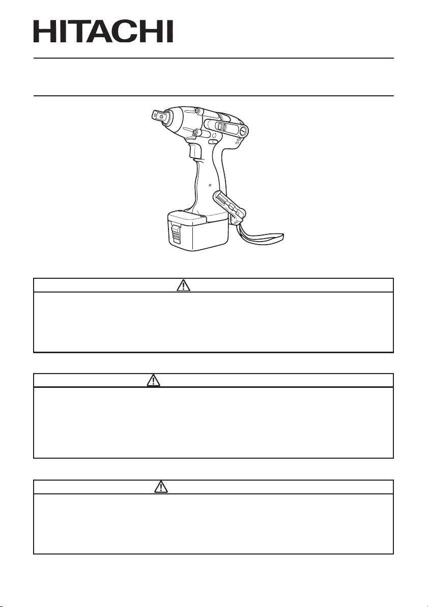
WR 12DM•WR 9DM
CORDLESS IMPACT WRENCH
CLÉ À CHOC À BATTERIE
LLAVE DE IMPACTO A BATERÍA
SAFETY INSTRUCTIONS AND INSTRUCTION MANUAL
WARNING
IMPROPER OR UNSAFE use of this power tool can result in death or serious bodily
injury!
This manual contains important information about product safety. Please read
and understand this manual BEFORE operating the power tool. Please keep this
manual available for other users and owners before they use the power tool. This
manual should be stored in safe place.
INSTRUCTIONS DE SECURITE ET MODE D’EMPLOI
AVERTISSEMENT
Une utilisation INCORRECTE OU DANGEREUSE de cet outil motorisé peut entraîner
la mort ou de sérieuses blessures corporelles!
Ce mode d’emploi contient d’importantes informations à propos de la sécurité de
ce produit. Prière de lire et de comprendre ce mode d’emploi AVANT d’utiliser
l’outil motorisé. Garder ce mode d’emploi à la disponibilité des autres utilisateurs
et propriétaires avant qu’ils utilisent l’outil motorisé. Ce mode d’emploi doit être
conservé dans un endroit sûr.
INSTRUCCIONES DE SEGURIDAD Y MANUAL DE INSTRUCCIONES
ADVERTENCIA
¡La utilización INAPROPIADA O PELIGROSA de esta herramienta eléctrica puede
resultar en lesiones de gravedad o la muerte!
Este manual contiene información importante sobre la seguridad del producto.
Lea y comprenda este manual ANTES de utilizar la herramienta eléctrica. Guarde
este manual para que puedan leerlo otras personas antes de utilizar la herramienta
eléctrica. Este manual debe ser guardado en un lugar seguro.
English
IMPORTANT SAFETY INFORMATION ............... 3
MEANINGS OF SIGNAL WORDS....................... 3
SAFETY .................................................................... 4
GENERAL SAFETY RULES – FOR ALL
BATTERY OPERATED TOOLS ..................... 4
SPECIFIC SAFETY RULES ................................... 6
IMPORTANT SAFETY INSTRUCTIONS FOR
USE OF THE CORDLESS IMPACT WRENCH ....
IMPORTANT SAFETY INSTRUCTIONS
FOR BATTERY CHARGER............................ 7
IMPORTANT SAFETY INSTRUCTIONS
FOR USE OF THE BATTERY AND
BATTERY CHARGER .................................... 9
FUNCTIONAL DESCRIPTION ................................ 10
MODEL ............................................................... 10
NAME OF PARTS .............................................. 10
CONTENTS
Page
SPECIFICATIONS .............................................. 11
ASSEMBLY AND OPERATION ............................. 12
APPLICATIONS.................................................. 12
REMOVAL AND INSTALLATION METHOD
OF BATTERY .................................................. 12
CHARGING METHOD........................................ 12
BEFORE USE ..................................................... 15
7
OPERATION ....................................................... 15
OPERATIONAL CAUTIONS .............................. 16
MAINTENANCE AND INSPECTION ..................... 21
ACCESSORIES ....................................................... 23
STANDARD ACCESSORIES ............................. 23
OPTIONAL ACCESSORIES ............................... 23
Page
Français
INFORMATIONS IMPORTANTES DE SÉCURITÉ
SIGNIFICATION DES MOTS D’AVERTISSEMEN
SECURITE ................................................................ 30
REGLES GENERALE DE SECURITE – POUR TOUS
LES OUTILS FONCTIONNANT SUR BATTERIE ...
REGLES DE SECURITE SPECIFIQUES ............... 32
CONSIGNES DE SÉCURITÉ IMPORTANTES POUR
L'UTILISATION DU CLÉ À CHOC À BATTERIE
CONSIGNES DE SÉCURITÉ IMPORTANTES
POUR L’UTILISATION DU CHARGEUR DE BATTERIE ...
CONSIGNES DE SÉCURITÉ IMPORTANTES POUR L’UTILISATION
DE LA BATTERIE ET DU CHARGEUR DE BATTERIE ...............
DESCRIPTION FONCTIONNELLE ........................... 37
MODELE ............................................................... 37
NOM DES PARTIES............................................. 37
Español
INFORMACIÓN IMPORTANTE SOBRE SEGURIDAD
SIGNIFICADO DE LAS PALABRAS DE SEÑALIZACIÓN
SEGURIDAD ............................................................. 59
NORMAS GENERALES DE SEGURIDAD – PARA TODAS
LAS HERRAMIENTAS ALIMENTADAS CON BATERÍA
NORMAS ESPECÍFICOS DE SEGURIDAD ......... 61
INSTRUCCIONES IMPORTANTES PARA LA UTILIZACIÓN
DEL LLAVE DE IMPACTO A BATERÍA ..........................
INSTRUCCIONES IMPORTANTES DE SEGURIDAD
PARA EL CARGADOR DE BATERÍAS
INSTRUCCIONES IMPORTANTES DE SEGURIDAD
PARA LA BATERÍA Y EL CARGADOR DE BATERÍAS
DESCRIPCIÓN FUNCIONAL .................................... 66
MODELO .............................................................. 66
NOMENCLATURA ............................................... 66
TABLE DES MATIERES
Page
.. 29
T .... 29
30
.....
33
34
35
ÍNDICE
Página
.... 58
.. 58
.. 59
62
................. 63
... 64
SPECIFICATIONS ................................................ 38
ASSEMBLAGE ET FONCTIONNEMENT ..........................
UTILISATIONS ..................................................... 39
MÉTHODE DE RETRAIT ET D’INSTALLATION
DE LA BATTERIE .......................................... 39
MÉTHODE DE RECHARGE ................................. 39
AVANT L’UTILISATION ...................................... 42
UTILISATION ....................................................... 42
PRÉCAUTIONS D'UTILISATION......................... 45
ENTRETIEN ET INSPECTION .................................. 49
ACCESOIRES ........................................................... 52
ACCESSOIRES STANDARD ............................... 52
ACCESSOIRES EN OPTION ................................ 52
ESPECIFICACIONES ............................................ 67
MONTAJE Y OPERACIÓN....................................... 68
APLICACIONES ................................................... 68
MÉTODO DE EXTRACCIÓN E INSTALACIÓN
DE LA BATERÍA ............................................ 68
MÉTODO DE CARGA .......................................... 68
ANTES DE LA UTILIZACIÓN .............................. 71
OPERACIÓN ......................................................... 71
PRECAUCIONES OPERACIONALES .................. 73
MANTENIMIENTO E INSPECCIÓN ........................ 78
ACCESORIOS ........................................................... 81
ACCESORIOS ESTÁNDAR.................................. 81
ACCESORIOS OPCIONALES .............................. 81
Page
Página
39

English
IMPORTANT SAFETY INFORMATION
Read and understand all of the safety precautions, warnings and operating instructions in
the Instruction Manual before operating or maintaining this power tool.
Most accidents that result from power tool operation and maintenance are caused by the
failure to observe basic safety rules or precautions. An accident can often be avoided by
recognizing a potentially hazardous situation before it occurs, and by observing appropriate
safety procedures.
Basic safety precautions are outlined in the “SAFETY” section of this Instruction Manual and
in the sections which contain the operation and maintenance instructions.
Hazards that must be avoided to prevent bodily injury or machine damage are identified by
WARNINGS on the power tool and in this Instruction Manual.
NEVER use this power tool in a manner that has not been specifically recommended by
HITACHI.
MEANINGS OF SIGNAL WORDS
WARNING indicates a potentially hazardous situations which, if ignored, could result in
death or serious injury.
CAUTION indicates a potentially hazardous situations which, if not avoided, may result in
minor or moderate injury, or may cause machine damage.
NOTE emphasizes essential information.
3

English
SAFETY
GENERAL SAFETY RULES – FOR ALL BATTERY OPERATED TOOLS
WARNING: Read and understand all instructions.
Failure to follow all instructions listed below, may result in electric shock,
fire and/or serious personal injury.
SAVE THESE INSTRUCTIONS
1. Work Area
(1) Keep your work area clean and well lit. Cluttered benches and dark areas invite
accidents.
(2) Do not operate power tools in explosive atmospheres, such as in the presence of
flammable liquids, gases, or dust. Power tools create sparks which may ignite the
dust of fumes.
(3) Keep bystanders children, and visitors away while operating a power tool.
Distractions can cause you to lose control.
2. Electrical Safety
(1) A battery operated tool with integral batteries or a separate battery pack must be
recharged only with the specified charger for the battery.
A charger that may be suitable for one type of battery may create a risk of fire when
used with another battery.
(2) Use battery operated tool only with specifically designed battery pack.
Use of any other batteries may create a risk of fire.
3. Personal Safety
(1) Stay alert, watch what you are doing and use common sense when operating a
power tool. Do not use tool while tired or under the influence of drugs, alcohol, or
medication. A moment of inattention while operating power tools may result in
serious personal injury.
(2) Dress properly. Do not wear loose clothing or jewelry. Contain long hair. Keep your
hair, clothing and gloves away from moving parts. Loose clothes, jewelry, or long hair
can be caught in moving parts.
(3) Avoid accidental starting. Be sure switch is off position before inserting battery.
Carrying tools with your finger on the switch or inserting the battery pack into a tool
with the switch on invites accidents.
(4) Remove adjusting keys or wrenches before turning the tool on. A wrench or a key that
is left attached to a rotating part of the tool may result in personal injury.
(5) Do not overreach. Keep proper footing and balance at all times. Proper footing and
balance enable better control of the tool in unexpected situations.
(6) Use safety equipment. Always wear eye protection. Dust mask, non-skid safety
shoes, hard hat, or hearing protection must be used for appropriate conditions.
4

English
4. Tool Use and Care
(1) Use clamps or other practical way to secure and support the workpiece to a stable
platform. Holding the work by hand or against your body is unstable and may lead to
loss of control.
(2) Do not force tool. Use the correct tool for your application. The correct tool will do
the job better and safer at the rate for which it is designed.
(3) Do not use tool if switch does not turn it on or off. Any tool that cannot be controlled
with the switch is dangerous and must be repaired.
(4) Disconnect battery pack from tool or place the switch in the locked or off position
before making any adjustments, changing accessories, or storing the tools. Such
preventive safety measures reduce the risk of starting the tool accidentally.
(5) Store idle tools out of reach of children and other untrained persons. Tools are
dangerous in the hands of untrained users.
(6) When battery pack is not in use, keep it away from other metal objects like: paper
clips, coins, keys, nails, screws, or other small metal objects that can make a
connection from one terminal to another.
Shorting the battery terminals together may cause sparks, burns, or a fire.
(7) Maintain tools with care. Keep cutting tools sharp and clean. Properly maintained
tools, with sharp cutting edges are less likely to bind and are easier to control.
(8) Check for misalignment or binding of moving parts, breakage of parts, and any other
condition that may affect the tools operation. If damaged, have the tool serviced
before using. Many accidents are caused by poorly maintained tools.
(9) Use only accessories that are recommended by the manufacturer for your model.
Accessories that may be suitable for one tool, may become hazardous when used on
another tool.
5. Service
(1) Tool service must be performed only by qualified repair personnel. Service or
maintenance performed by unqualified personnel could result in a risk of injury.
(2) When servicing a tool, use only identical replacement parts. Follow instructions in
the Maintenance section of this manual. Use of unauthorized parts or failure to follow
Maintenance Instruction may create a risk of electric shock or injury.
WARNING:
Some dust created by power sanding, sawing, grinding, drilling, and other construction activities contains chemicals known to the State of California to cause cancer,
birth defects or other reproductive harm. Some examples of these chemicals are:
● Lead from lead-based paints,
● Crystalline silica from bricks and cement and other masonry products, and
● Arsenic and chromium from chemically-treated lumber.
Your risk from these exposures varies, depending on how often you do this type
of work. To reduce your exposure to these chemicals: work in a well ventilated area,
and work with approved safety equipment, such as those dust masks that are specially
designed to filter out microscopic particles.
5

English
SPECIFIC SAFETY RULES
1. Hold tools by insulated gripping surfaces when performing an operation where the
cutting tool may contact hidden wiring. Contact with a “live” wire will make exposed
metal parts of the tool “live” and shock the operator.
2. Never touch moving parts.
Never place your hands, fingers or other body parts near the tool’s moving parts.
3. Never operate without all guards in place.
Never operate this tool without all guards or safety features in place and in proper
working order. If maintenance or servicing requires the removal of a guard or safety
feature, be sure to replace the guard or safety feature before resuming operation of the
tool.
4. Use right tool.
Don’t force small tool or attachment to do the job of a heavy-duty tool.
Don’t use tool for purpose not intended —for example— don’t use circular saw for cutting
tree limbs or logs.
5. Never use a power tool for applications other than those specified.
Never use a power tool for applications other than those specified in the Instruction
Manual.
6. Handle tool correctly.
Operate the tool according to the instructions provided herein. Do not drop or throw the
tool. Never allow the tool to be operated by children, individuals unfamiliar with its
operation or unauthorized personnel.
7. Definitions for symbols
V .... volts
— ............. direct current
---
no............ no load speed
---/min ..... revolutions or reciprocation per minute
8. Keep all screws, bolts and covers tightly in place.
Keep all screws, bolts, and plates tightly mounted. Check their condition periodically.
9. Do not use power tools if the plastic housing or handle is cracked.
Cracks in the tool’s housing or handle can lead to electric shock. Such tools should not
be used until repaired.
10. Blades and accessories must be securely mounted to the tool.
Prevent potential injuries to youself or others. Blades, cutting implements and accessories which have been mounted to the tool should be secure and tight.
11. Never use a tool which is defective or operating abnormally.
If the tool appears to be operating unusually, making strange noises, or otherwise
appears defective, stop using it immediately and arrange for repairs by a Hitachi
authorized service center.
12. Carefully handle power tools.
Should a power tool be dropped or struck against hard materials inadvertently, it may be
deformed, cracked, or damaged.
13. Do not wipe plastic parts with solvent.
Solvents such as gasoline, thinner benzine, carbon tetrachloride, and alcohol may
damage and crack plastic parts. Do not wipe them with such solvents.
Wipe plastic parts with a soft cloth lightly dampened with soapy water and dry
thoroughly.
6

English
IMPORTANT SAFETY INSTRUCTIONS FOR USE OF THE
CORDLESS IMPACT WRENCH
WARNING: Death or serious bodily injury could result from improper or unsafe use
of the cordless impact wrench. To avoid these risks, follow these basic
safety instructions:
1. Never use this wrench handle for any application other than those in this manual.
2. When working in high places, always make sure that there is no one below before starting
to work.
3. Always wear eye and ear protection when you work.
4. Confirm whether the socket has any crack in it.
5. Attach the hex. socket securely onto the anvil. If the hex. socket is insufficiently secured,
it may drop out and cause an accident. For hex. socket attachment refer to “OPERATION”
on page 15.
6. Confirm the tightening torque by a torque wrenck before use in order to ascertain the
correct tightening torque to be used.
7. If a universal joint is used, be sure not to operate the unit in a no-load condition. Operatig
in this condition is dangerous. When the socket section spins around it may cause injury
to hands or bodies, or the resuluting intense vibration may cause the user to drop the tool.
8. Be careful that foreign matters do not block the holes located on both sides of the handle.
Also do not close the holes with a tape. The holes act an important role.
IMPORTANT SAFETY INSTRUCTIONS
FOR BATTERY CHARGER
1. This manual contains important safety and operating instructions for battery charger
Model UC14YF2.
2. Before using battery charger, read all instructions and cautionary markings on (1) battery
charger, (2) battery, and (3) product using battery.
3. To reduce risk of injury, charge HITACHI rechargeable battery type EB7, EB9, EB12, EB14
series. Other type of batteries may burst causing personal injury and damage.
4. Do not expose battery charger to rain or snow.
5. Use of an attachment not recommended or sold by the battery charger manufacturer may
result in a risk of fire, electric shock, or injury to persons.
6. To reduce risk of damage to electric plug and cord, pull by plug when disconnecting
battery charger.
7. Make sure cord is located so that it will not be stepped on, tripped over, or otherwise
subjected to damage or stress.
8. An extension cord should not be used unless absolutely necessary. Use of improper
extension cord could result in a risk of fire and electric shock.
If extension cord must be used make sure:
7

English
a. That blades of extension cord are the same number, size, and shape as those of plug
on battery charger:
b. That extension cord is properly wired and in good electrical condition; and
c. That wire size is large enough for AC ampere rating of battery charger as specified
in Table 1.
Table 1
RECOMMENDED MINIMUM AWG SIZE FOR
EXTENSION CORDS FOR BATTERY CHARGERS
AC Input Rating Amperes* AWG Size of Cord
Equal to or but less Length of Cord, Feet (Meter)
greater than than 25 (7.5) 50 (15) 100 (30) 150 (45)
0 2 18 18 18 16
2 3 18 18 16 14
3 4 18 18 16 14
* If the input rating of a battery charger is given in watts rather than in amperes, the
corresponding ampere rating is to be determined by dividing the wattage rating by the
voltage rating–for example:
1250watts
125 volts
= 10 amperes
9. Do not operate battery charger with damaged cord or plug-replace them immediately.
10. Do not operate battery charger if it has received a sharp blow, been dropped, or
otherwise damaged in any way; take it to a qualified serviceman.
11. Do not disassemble battery charger; take it to a qualified serviceman when service or
repair is required. Incorrect reassembly may result in a risk of electric shock or fire.
12. To reduce risk of electric shock, unplug charger from receptacle before attempting any
maintenance or cleaning. Removing the battery will not reduce this risk.
8
English
IMPORTANT SAFETY INSTRUCTIONS FOR USE OF THE
BATTERY AND BATTERY CHARGER
You must charge the battery before you can use the cordless impact wrench. Before using
the model UC14YF2 battery charger, be sure to read all instructions and cautionary
statements on it, the battery and in this manual.
REMEMBER: USE ONLY HITACHI BATTERY TYPES EB7 SERIES, EB9 SERIES, EB12 SERIES,
EB14 SERIES. OTHER TYPES OF BATTERIES MAY BURST AND CAUSE INJURY!
Follow these instructions to avoid the risk of injury:
WARNING: Improper use of the battery or battery charger can lead to serious injury.
To avoid these injuries:
1. NEVER disassemble the battery.
2. NEVER incinerate the battery, even if it is damaged or is completely worn out. The
battery can explode in a fire.
3. NEVER short-circuit the battery.
4. NEVER insert any objects into the battery charger’s air vents. Electric shock or
damage to the battery charger may result.
5. NEVER charge outdoors. Keep the battery away from direct sunlight and use only
where there is low humidity and good ventilation.
6. NEVER charge when the temperature is below 32°F (0°C) or above 104°F (40°C).
7. NEVER connect two battery chargers together.
8. NEVER insert foreign objects into the hole for the battery or the battery charger.
9. NEVER use a booster transformer when charging.
10. NEVER use an engine generator or DC power to charge.
11. NEVER store the battery or battery charger in places where the temperature may
reach or exceed 104°F (40°C).
12. ALWAYS operate charger on standard household electrical power (120 volts). Using
the charger on any other voltage may overheat and damage the charger.
13. ALWAYS wait at least 15 minutes between charges to avoid overheating the charger.
14. ALWAYS disconnect the power cord from its receptacle when the charger is not in use.
SAVE THESE INSTRUCTIONS
AND
MAKE THEM AVAILABLE TO
OTHER USERS
AND
OWNERS OF THIS TOOL!
9
English
FUNCTIONAL DESCRIPTION
NOTE: The information contained in this Instruction Manual is designed to assist you in the
safe operation and maintenance of the power tool.
NEVER operate, or attempt any maintenance on the tool unless you have first read
and understood all safety instructions contained in this manual.
Some illustrations in this Instruction Manual may show details or attachments that
differ from those on your own power tool.
MODEL
WR12DM: with charger (UC14YF2) and case
WR9DM: with charger (UC14YF2) and case
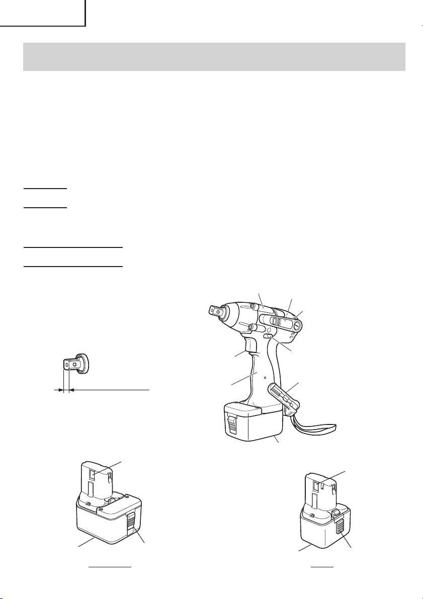
NAME OF PARTS
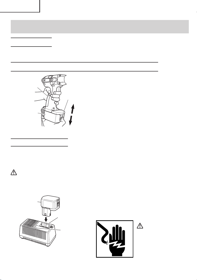
1. Cordless Impact Wrench
Housing
Nameplate
Air Vents
䡬 Battery
Nameplate
10
WR12DM: 1/2" (12.7 mm)
WR9DM: 3/8" (9.5 mm)
Terminal
Hole
Latch
Switch Trigger
Handle
Fig. 1
Push Button
Battery
Nameplate
Convenient
Hook
Terminal
Hole
Latch
EB9BEB1220BL
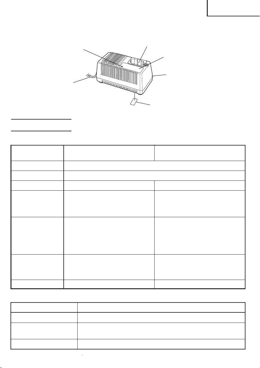
2. Battery Charger (UC14YF2)
English
Pilot Lamp
Cord
Battery Installation Hole
Caution Plate
Body
Nameplate
Fig. 2
SPECIFICATIONS
1. Cordless Impact Wrench
MODEL
Motor DC motor
No-load speed 0 – 2,300/min
Drive 3/8" (9.5 mm) square 1/2" (12.7 mm) square
Capacity 1/4" – 9/16" (M6 – M14) 1/4" – 5/8" (M6 – M16)
(Ordinary bolt) (Ordinary bolt)
1/4" – 3/8" (M6 – M10) 1/4" – 15/32" (M6 – M12)
(High tension bolt) (High tension bolt)
Tightening torque Maximum 780 in-lbs Maximum 1330 in-lbs
Tightening is 15/32" (M12) Tightening is 5/8" (M16) F10T,
high tension bolt, when fully when fully charged at 20°C
charged in 20°C temp. temp.
Tighttening time: 3 sec. Tightening time: 3 sec.
Rechargeable EB9B (2.0 Ah) EB1220BL (2.0 Ah)
battery Ni-Cd battery, 9.6V Ni-Cd battery, 12V
Charging and discharging Charging and discharging
Frequency: about 1000 Frequency: about 1000
Weight 3.0 lbs (1.4 kg) 3.5 lbs (1.6 kg)
WR9DM WR12DM
(9.6V) (12V)
(88.2 N·m, 900 kgf·m) (150 N·m, 1530 kgf·m)
2. Battery Charger (UC 14YF2)
Input power source Single phase: AC120V, 60Hz
Charging time Approx. 60min. (At a temperature of 68°F (20°C))
Charger
Weight 2.9 lbs (1.3kg)
Charging voltage .......................... DC 7.2–14.4V
Charging current........................... DC 1.9A
11
English
ASSEMBLY AND OPERATION
APPLICATIONS
䡬 Tightening and loosening of all types of bolts and nuts, used for securing structural
items.
REMOVAL AND INSTALLATION METHOD OF BATTERY
䡬 How to install the battery.
Align the battery with the groove in tool
Handle
Latch
Insert
Rechargeable
battery
Pull out
Fig. 3
CHARGING METHOD
handle and slip it into place.
Always insert it all the way until it locks in
place with a little click, If not, it may accidentally fall out of the tool, causing injury to
you or someone around you. (Fig. 3)
䡬 How to remove the battery.
Withdraw battery from the tool handle while
pressing the latch on the side of the battery.
(Fig. 3)
NOTE: Before plugging into the receptacle, make sure the following points.
䡬 The power source voltage is stated on the nameplate.
䡬 The cord is not damaged.
WARNING: Do not charge at voltage higher than indicated on the nameplate.
If charged at voltage higher than indicated on the nameplate, the
charger will burn up.
1. Insert the plug of battery charger into
Rechargeable
battery
12
d
Battery installation hole
Pilot lamp
Fig. 4
the receptacle.
When the plug of battery charger has been
inserted into the receptacle, pilot lamp will
blink in red. (At 1-second intervals)
WARNING:
Do not use the electrical
cord if damaged. Have
it repaired immediately.
English
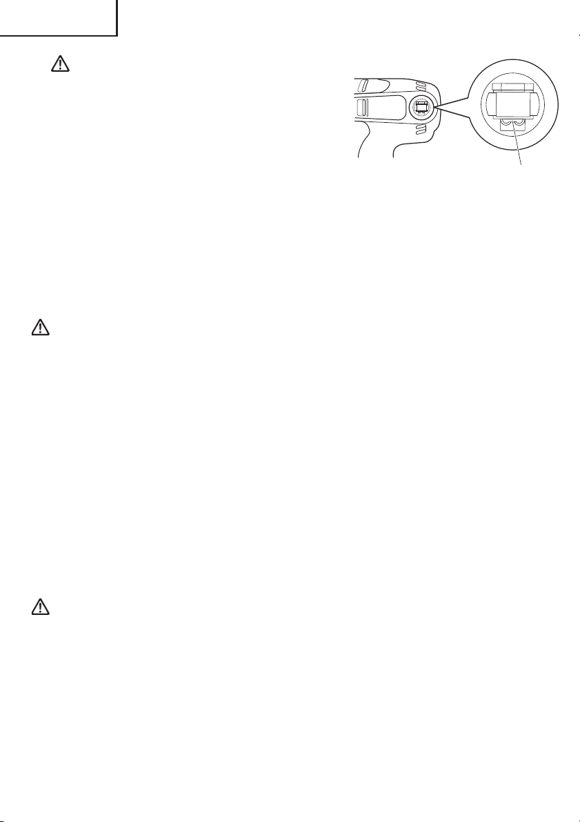
2. Insert the battery to the battery charger.
Insert the battery into the battery charger as shown in Fig. 4. Make sure it contacts the
bottom of the battery charger.
CAUTION:
● If the batteries are inserted in the reverse direction, not only recharging will become
impossible, but it may also cause problems in the charger such as a deformed recharging
terminal.
3. Charging
When the battery is connected to the battery charger, charging will commence and the
pilot lamp will light in red. (See Table 2)
NOTE: If the pilot lamp flikers in red, pull out the plug from the receptacle and check if
the battery is properly mounted.
When the battery is fully charged, the pilot lamp will blink in red slowly. (At 1-second
intervals) (See Table 2)
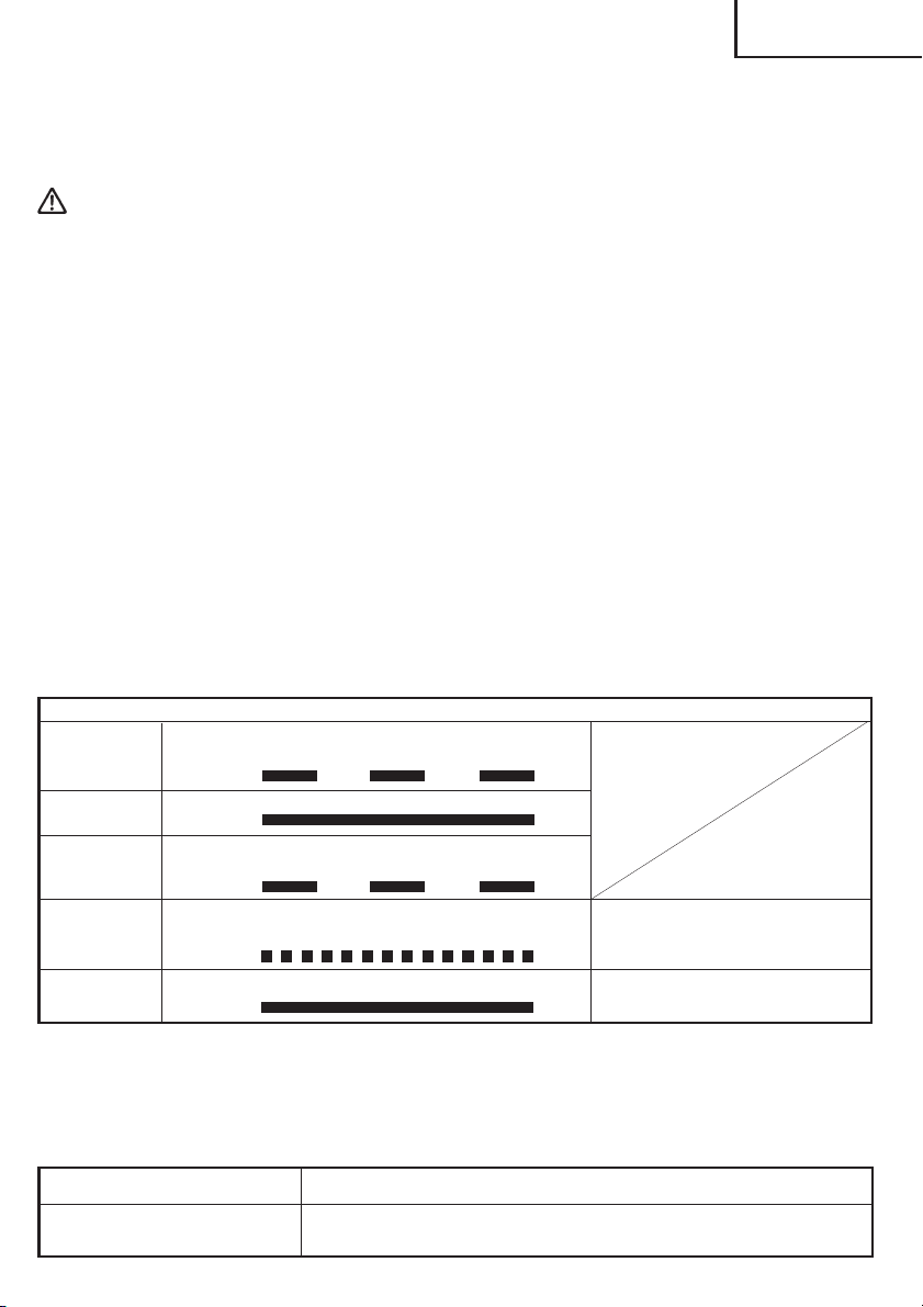
(1) Pilot lamp indication
The indications of the pilot lamp will be as shown in Table 2, according to the condition
of the charger or the rechargeable battery.
Table 2
Indications of the pilot lamp
Before
charging
While
charging
Charging
complete
Charging
impossible
Charging
impossible
Blinks
(RED)
Lights
(RED)
Blinks
(RED)
Flikers
(RED)
Lights
(GREEN)
Lights for 0.5 seconds. Does not light for
0.5 seconds. (off for 0.5 seconds)
Lights continuously
Lights for 0.5 seconds. Does not light for
0.5 seconds. (off for 0.5 seconds)
Lights for 0.1 seconds. Does not light for
0.1 seconds. (off for 0.1 seconds)
Lights continuously
Malfunction in the battery or the
charger
The battery temperature is high,
making recharging impossible.
(2) Regarding the temperature of the rechargeable battery.
The temperatures for rechargeable batteries are as shown in the table below, and
batteries that have become hot should be cooled for a while before being recharged.
Table 3 Recharging of batteries that have become hot
Rechargeable batteries
EB9B, EB1220BL
Temperatures at which the battery can be recharged
23°F—140°F
(–5°C—60°C)
13

English
(3) Regarding recharging time (At 68°F (20°C))
In approx. 60 minutes.
NOTE: The charging time may vary according to temperature and power source voltage.
4. Disconnect battery charger from the receptacle.
CAUTION:
Do not pull the plug out of the receptacle by pulling on the cord.
Make sure to grasp the plug when removing from receptacle to avoid damaging cord.
5. Remove the battery from the battery charger.
Supporting the battery charger with hand, pull out the battery from the battery charger.
CAUTION:
● When the battery charger has been continuosly used, the battery charger will be heated,
thus constituting the cause of the failures. Once the charging has been completed, give
15 minutes rest until the next charging.
● If the battery is rechraged when it is warm due to battery use or exposure to sunlight,
the pilot lamp may light in green.
The battery will not be recharged. In such a case, let the battery cool before charging.
● When the pilot lamp flikers rapidly in red (at 0.2–second intervals), check for and take
out any foreign objects in the charger’s battery installation hole. If there are no foreign
objects, it is probable that the battery or charger is malfunctioning. Take it to your
authorized Service Center.
● Since the built-in micro computer takes about 3 seconds to confirm that the battery
being charged with UC14YF2 is taken out, wait for a minimum of 3 seconds before
reinserting it to continue charging. If the battery is reinserted within 3 seconds, the
battery may not be properly charged.
Regarding electric discharge in case of new batteries, etc.
As the internal chemical substance of new batteries and batteries that have not been
used for an extended period is not activated, the electric discharge might be low when
using them the first and second time. This is a temporary phenomenon, and normal time
required for recharging will be restored by recharging the batteries 2 – 3 times.
How to make the batteries perform longer.
(1) Recharge the batteries before they become completely exhausted.
When you feel that the power of the tool becomes weaker, stop using the tool and
recharge its battery. If you continue to use the tool and exhaust the electric current, the
battery may be damaged and its life will become shorter.
(2) Avoid recharging at high temperatures.
A rechargeable battery will be hot immediately after use. If such a battery is recharged
immediately after use, its internal chemical substance will deteriorate, and the battery
life will be shortened. Leave the battery and recharge it after it has cooled for a while.
14
English
BEFORE USE
Check the work area to make sure that it is clear of debris and clutter.
Clear the area of unnecessary personnel. Ensure that lighting and ventilation is adequate.
OPERATION
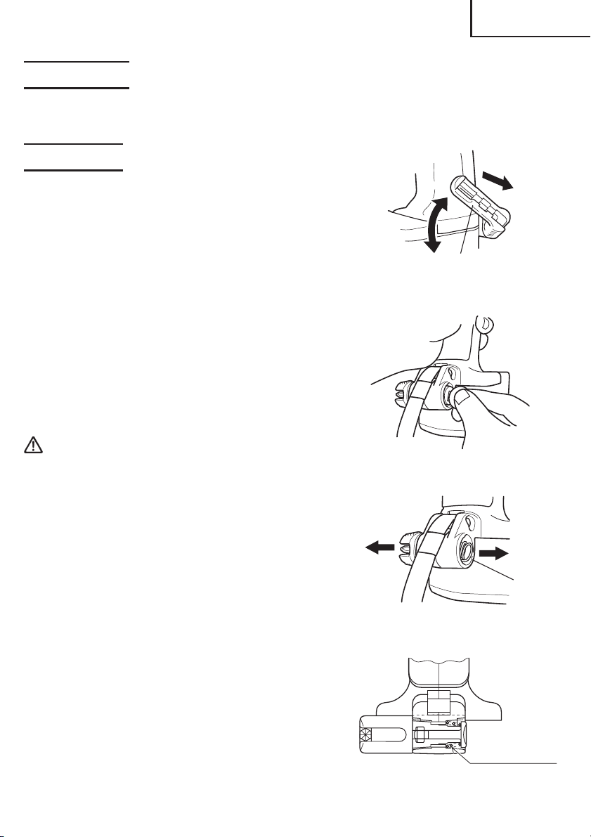
1. Using the convenient hook
The convenient hook can be installed on the right
or left side and the angle can be adjusted in 5 steps
between 0 and 80.
(1) Operating the hook
(a) Pull out the hook toward you in the direction of
arrow (A) and turn in the direction of arrow (B).
(Fig. 5)
(b) The angle can be adjusted in 5 steps (0°, 20°, 40°,
60°, 80°).
Adjust the angle of the hook to the desired
position for use.
(2) Switching the hook position
CAUTION:
● If the tool falls, there is a risk that malfunction and/
or physical damage can occur. It is recommended
that you also use fall-preventing wires, etc.
● Incomplete installation of the hook may result in
bodily injury when used.
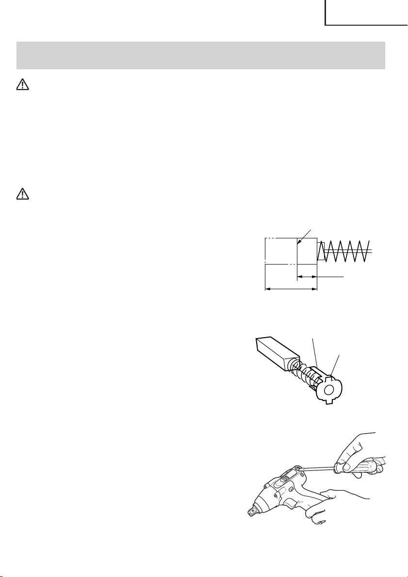
(a) Securely hold the main unit and remove the
screw using a slotted head screwdriver or a
coin. (Fig. 6)
(b) Remove the hook and spring. (Fig. 7)
(c) Install the hook and spring on the other side
and securely fasten with screw. (Fig. 8)
Convenient Hook
Fig. 5
Fig. 6
Spring
Fig. 7
NOTE:
Pay attention to the spring orientation. Install
the spring with larger diameter away from you.
(Fig. 8)
Larger diameter
faces away
Fig. 8
15
English
R
2. Selecting the socket matched to the bolt
Be sure to use a socket which is matched to the bolt
to be tightened. Using an improper socket will not
only result in insufficient tightening but also in
damage to the socket or nut.
A worn or deformed hex or square-holed socket
will not give an adequate tightness for fitting to the
nut or anvil, consequently resulting in loss of tightening torque.
Pay attention to wear of socket hole, and replace
before further wear has developed.
Matching socket and bolt sizes are shown Tables 4,
5, 6 and 7. The numerical value of a socket
designation denotes the side-to-side distance (H)
of its hex. hole.
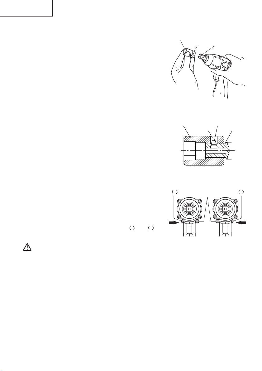
3. Installing a socket (Fig. 9, 10)
Align the plunger located in the square part of the
anvil with the hole in the hex. socket. Then push the
plunger, and mount the hex. socket on the anvil.
Check that the plunger is fully engaged in the hole.
When removing the socket, reverse the sequence.
4. Removing the socket
Please do the opposite point on the method of
installing socket.
5. Confirm that the battery is mounted correctly.
Hexagonal
socket
Hexagonal
socket
R
Groove
Fig. 9
Hole
Fig. 10
Push
button
Anvil
Plunger
6. Check the rotational direction
The bit rotates clockwise (viewed from the rear
side) by pushing the R-side of the push button.
The L-side of the push button is pushed to turn the
bit counterclockwise. (See Fig. 11). (The L and
marks are engraved on the body.)
CAUTION
The push button can not be switched while the impact driver is turning. To switch the
push button, stop the impact driver, then set the push button.
Push
Fig. 11
Anvil
L
Push
7. Switch operation
䡬 When the trigger switch is depressed, the tool rotates. When the trigger is released, the
tool stops.
䡬 The rotational speed can be controlled by varying the amount that the trigger switch is
pulled. Speed is low when the trigger switch is pulled slightly and increases as the trigger
switch is pulled more.
NOTE
A buzzing noise is produced when the motor is about to rotate; this is only a noise, not
a machine failure.
16
English
8. Tightening and loosening bolts
A hex socket matching the bolt or nut must first be selected. Then mount the socket on
the anvil, and grip the nut to be tightened with the hex socket. Holding the wrench in line
with the bolt, press the power switch to impact the nut for several seconds.
If the nut is only loosely fitted to the bolt, the bolt may turn wit the nut, therefore mistaking
proper tightening. In this case, stop impact on the nut and hold the bolt head with a
wrench before restarting impact, or manually tighten the bolt and nut to prevent them
slipping.
9. Number of bolt tightened possible
Please refer to the table below for the number of bolt tightened possible with one charge.
<For WR12DM> (EB1220BL)
Bolt used No. of tightenings
5/8" × 2–5/32" (M16 × 55) F10T bolt Approx. 90
<For WR9DM> (EB9B)
Bolt used No. of tightenings
Ordinary bolt 15/32" × 1–3/4" (M12 × 45) Approx. 90
These values may vary slightly, according to surrounding temperature and battery
characteristics.
OPERATIONAL CAUTIONS
1. Resting the unit after continuous work
After use for continuous bolt-tightening work, rest the unit for 15 minutes or so when
replacing the battery. The temperature of the motor, switch, etc., will rise if the work is
started again immediately after battery replacement, eventually resulting in burnout.
CAUTION: Do not touch the hammer case, as it gets very hot during continuous
work.
2. Cautions on use of the speed control switch
This switch has a built-in, electronic circuit which steplessly varies the rotation speed.
Consequently, when the switch trigger is pulled only slightly (low speed rotation) and the
motor is stopped while continuously driving in screws, the components of the electronic
circuit parts may overheat and be damaged.
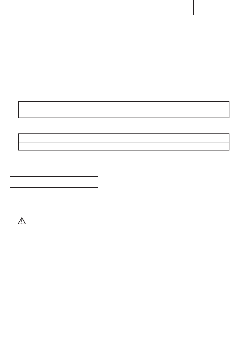
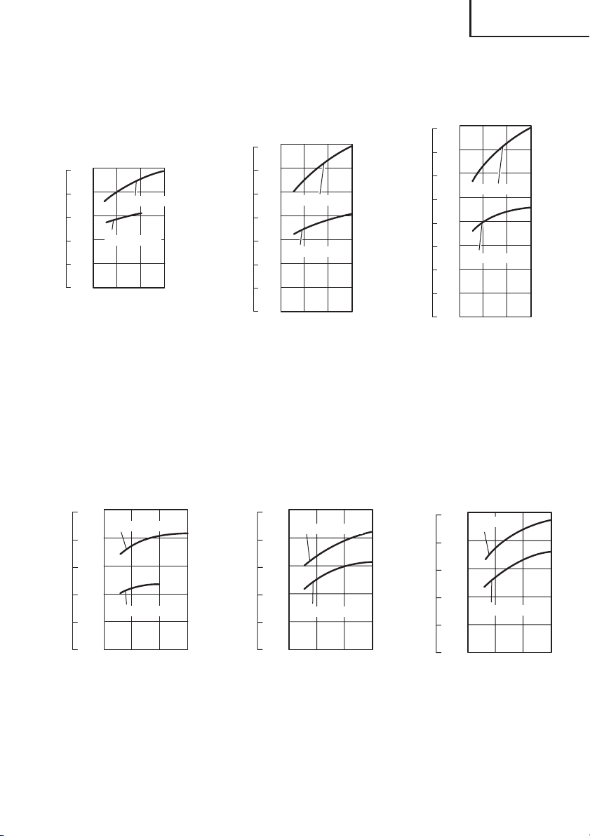
3. Tightening torque
Refer to Fig. 12 and 13 for the tightening torque of bolts (according to size), under the
conditions shown in Fig. 14. Please use this example as a general reference, as tightening
torque will vary according to tightening conditions.
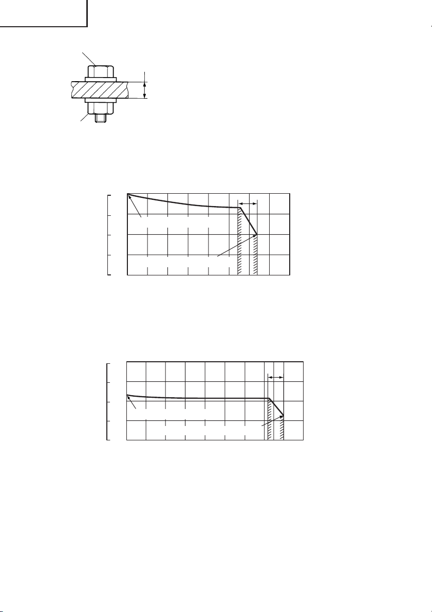
Tightening torque varies, depending on the battery’s charge level. Fig. 15 and 16 shows
an example of the relationship between tightening torque and the number of tightenings
(WR12DM and WR9DM). As shown, tightening torque gradually weakens with the
increase in the number of tightenings. In particular, as the torque decreases very close
to the complete discharge (“a” margin in graph), the unit’s impact weakens, the number
of time impacts declines and tightening torque drops off abruptly. If this occurs, check
torque level, then recharge the battery if necessary.
17

English
NOTE
䡬 If a long striking time is used, screws will be strongly tightened. This may cause the screw
to break, or may damage the end of the bit.
䡬 If the unit is held at an angle to the screw being tightened, the head of the screw may be
damaged, or the specified torque may not be transmitted to the screw. Always keep the
unit and the screw being tightened in a straight line.
4. Use a tightening time suitable for the screw
The appropriate torque for a screw differs according to the material and size of the screw,
and the material being screwed etc., so please use a tightening time suitable for the
screw. In particular, if a long tightening time is used in the case of screws smaller than
5/16" (8 mm), there is a danger of the screw breaking, so please confirm the tightening
time and the tightening torque beforehand.
5. Work at a tightening torque suitable for the bolt under impact
The optimum tightening torque for nuts or bolts differs with material and size of the nuts
or bolts. An excessively large tightening torque for a small bolt may stretch or break the
bolt. The tightening torque increases in proportionate to the operaton time. Use the
correct operating time for the bolt.
6. Holding the tool
Hold the impact wrench firmly with both hands. In this case hold the wrench in line with the bolt.
It is not necessary to push the wrench very hard. Hold the wrench with a force just
sufficient to counteract the impact force.
7. Confirm the tightening torque
The following factors contribute to a reduction of the tightening torque. So confirm the
actual tightening torque needed by screwing up some bolts before the job with a hand
torque wrench. Factors affecting the tightening torque are as follows.
(1) Voltage
When the discharge margin is reached, voltage decreases and tightening torque is
lowered.
(2) Operating time
The tightening torque increases when the operating time increases. But the tightening
torque does not increase above a certain value even if the tool is driven for a long time.
(See Fig. 12 and 13)
(3) Diameter of bolt
The tightening torque differs with the diameter of the bolt as shown in Fig. 12 and 13.
Generally a larger diameter bolt requires larger tightening torque.
(4) Tightening conditions
The tightening torque differs according to the torque ratio; class, and length of bolts even
when bolts with the same size threads are used. The tightening torque also differs
according to the condition of the surface of workpiece through which the bolts are to be
tightened. When the bolt and nut turn together, torque is greatly reduced.
(5) Using optional parts
The tightening torque is reduced a little when an extension bar, universal joint or a long
socketis used.
(6) Clearance of the socket
A worn or deformed hex or a square-holed socket will not give an adequate tightness to
the fitting between the nut or anvil, consequently resulting in loss of tightening torque.
Using an improper socket which does not match to the bolt will result in an insufficient
tightening torque. Matching socket and bolt sizes are shown in Table 4, 5, 6 and 7.
18
1000
(868)
800
(694)
600
(521)
400
(347)
200
(174)
0
100
80
60
40
20
0
0
1 2 3
<For WR12DM>
kgf·cm
(in-lbs) (M10×30)
1000
(868)
800
(694)
600
(521)
400
(347)
200
(174)
Tightening torque
0
N·m
100
80
60
40
20
0
3/8"×1-5/32"
Ordinary bolt
0 1
Tightening time: sec
(Steel plate thickness
t = 3/8" (10 mm))
<For WR9DM>
High strenge
bolt
2 3
kgf·cm
(in-lbs) (M12×45)
1400
(1215)
1200
(1642)
1000
(868)
800
(694)
600
(521)
400
Tightening torque
(347)
200
(174)
N·m
140
120
100
0
15/32"×1-3/4"
High strenge bolt
80
60
Ordinary bolt
40
20
0
0 1
2 3
Tightening time: sec
(Steel plate thickness
t = 1" (25 mm))
Fig. 12
English
kgf·cm
(in-lbs) (M14×50)
1600
(1389)
1400
(1215)
1200
(1042)
1000
(868)
800
(694)
600
(521)
Tightening torque
400
(347)
200
(174)
9/16"×1-15/16"
N·m
160
140
120
High strenge bolt
100
80
60
Ordinary bolt
40
20
0
0
0 1
2 3
Tightening time: sec
(Steel plate thickness
t = 1" (25 mm))
kgf·cm
(in-lbs) (M8×30)
1000
(868)
800
(694)
600
(521)
400
(347)
Tightening torque
200
(174)
0
5/16"×1-3/6"
N·m
100
High strenge bolt
80
60
40
Ordinary bolt
20
0
0
Tightening time: sec
(Steel plate thickness
t = 3/8" (10 mm))
1 2 3
kgf·cm
(in-lbs) (M10×30)
1000
(868)
800
(694)
600
(521)
400
(347)
Tightening torque
200
(174)
0
3/8"×1-3/6"
N·m
100
High strenge bolt
80
60
40
20
0
0
Ordinary bolt
1 2 3
Tightening time: sec
(Steel plate thickness
t = 3/8" (10 mm))
Fig. 13
kgf·cm
(in-lbs) (M12×45)
Tightening torque
N·m
High strenge
bolt
15/32"×1-3/4"
Ordinary bolt
Tightening time: sec
(Steel plate thickness
t = 1" (25 mm))
19
English
Bolt
Nut
<For WR12DM>
Tightening torque
<For WR9DM>
Tightening torque
Steel plate
thickness t
*The following bolt is used.
Ordinary bolt: Strength grade 4.8
High tensile bolt: Hardness division 12.9
Explanation of strength grade:
4 — Yield point of bolt: 45,500 psi (32 kgf/mm
()
8 — Pulling strength of bolt: 56,900 psi (40 kgf/mm
Fig. 14
kgf·cm
N·m 5/8" × 2–5/32" (M16 × 55) F10T bolt (tightening time 3 sec)
(in-lbs)
160
1600
(1389)
120
1200
(1042)
800
(694)
400
(347)
0
When full recharged
80
40
When complately discharged
0
0
20 40 60
Number of tightenings (PCS)/charging
80 100 120 140
Fig. 15
kgf·cm
N·m 15/32" × 1–3/4" (M12 × 45) High tension bolt
(in-lbs)
(tightening time 3 sec)
160
1600
(1389)
120
1200
(1042)
800
(694)
400
(347)
80
When full recharged
40
0
0
0
When complately discharged
20 40 60
Number of tightenings (PCS)/charging
80 100 120 140 160
Fig. 16
2
)
2
)
a
a
20
English
MAINTENANCE AND INSPECTION
CAUTION: Pull out battery before doing any inspection or maintenance.
1. Checking the condition of the socket.
A worn or deformed hex or a square-holed socket will not give an adequate tihgtness to
the fitting between the nut or anvil, consequently resulting in loss of tihgtening torque.
Pay attention to wear of a socket holes periodically, and replace with a new one if needed.
2. Check the Screws
Loose screws are dangerous. Regularly inspect them and make sure they are tight.
CAUTION: Using this power tool with loosened, screws is extremely dangerous.
3. Maintenance of the motor
The motor unit winding is the very “heart” of the
power tool.
Exercise due care to ensure the winding does not
become damaged and/or wet with oil or water.
4. Inspecting the carbon brushes (Fig. 17)
The motor employs carbon brushes which are
consumable parts. Since and excessively worn
carbon brush can result in motor trouble, replace
the carbon brush with new ones when it becomes
worn to or near the “wear limit”. In addition,
always keep carbon brushes clean and ensure that
they slide freely within the brush holders.
NOTE:
When replacing the carbon brush with a new one,
be sure to use the Hitachi Carbon Brush Code No.
999054.
5. Replacing carbon brushes
Take out the carbon brush by first removing the
brush cap and then hooking the protrusion of the
carbon brush with a flat head screw driver, etc., as
shown in Fig. 19.
When installing the carbon brush, choose the direction so that the nail of the carbon brush agrees
with the contact portion outside the brush tube.
Then push it in with a finger as illustrated in Fig. 20.
Lastly, install the brush cap.
Wear limit
0.12" (3mm)
0.45"
(11.5mm)
Fig. 17
Nail of carbon brush
Protrusion
of carbon
brush
Fig. 18
Fig. 19
21
English
CAUTION:
Be absolutely sure to insert the nail of the carbon
brush into the contact portion outside the brush
tube. (You can insert whichever one of the two
nails provided.)
Caution must be exercised since any error in this
operation can result in the deformed nail of the
carbon brush and may cause motor trouble at an
early stage.
Contact portion
outside brush tube
6. Check for Dust
Dust may be removed with a soft cloth or a cloth
dampened with soapy water.
Do not use bleach, chlorine, gasoline or thinner, for
they may damage the plastics.
Fig. 20
7. Disposal of the exhausted battery
WARNING: Do not dispose of the exhausted battery. The battery must explode if it
is incinerated. The product that you have purchased contains a rechargeable battery. The battery is recyclable. At the end of it’s useful
life, under various state and local laws, it may be illegal to dispose of this
battery into the municipal waste stream. Check with your local solid
waste officials for details in your area for recycling options or proper
disposal.
8. Storage
Storing in a place below 104°F (40°C) and out of the reach of children.
9. Service and repairs
All quality power tools will eventually require servicing or replacement of parts because
of wear from normal use. To assure that only authorized replacement parts will be used,
all service and repairs must be performed by a HITACHI AUTHORIZED SERVICE CENTER,
ONLY.
10.Service parts list
CAUTION: Repair, modification and inspection of Hitachi Power Tools must be carried
out by an Hitachi Authorized Service Center.
This Parts List will be helpful if presented with the tool to the Hitachi
Authorized Service Center when requesting repair or other maintenance. In
the operation and maintenance of power tools, the safety regulations and
standards prescribed in each country must be observed.
MODIFICATIONS:
Hitachi Power Tools are constantly being improved and modified to incorporate the latest
technological advancements.
Accordingly, some parts (i.e. code numbers and/or design) may be changed without prior
notice.
22
English
ACCESSORIES
WARNING: ALWAYS use Only authorized HITACHI replacement parts and
accessories. NEVER use replacement parts or accessories which are not
intended for use with this tool. Contact HITACHI if you are not sure
whether it is safe to use a particular replacement part or accessory with
your tool.
The use of any other attachment or accessory can be dangerous and
could cause injury or mechanical damage.
NOTE:
Accessories are subject to change without any obligation on the part of the HITACHI.
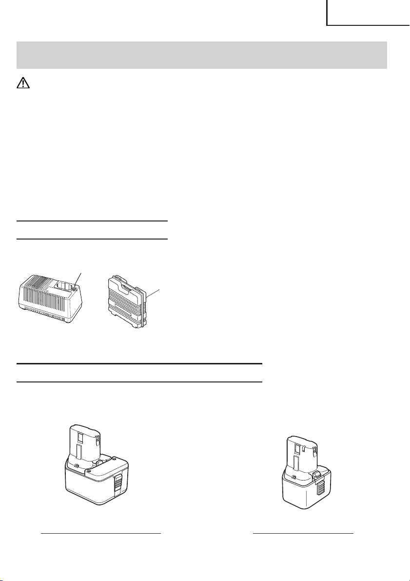
STANDARD ACCESSORIES
1
2
1 Battery Charger (UC14YF2).......................... 1
2 Plastic Case (Code No. 319924) ................... 1
Fig. 21
OPTIONAL ACCESSORIES.....sold separately
1. Battery
EB1220BL (Code No. 320386) EB9B (Code No. 310451)
Fig. 22
23
English
H S
L
L1
ØF
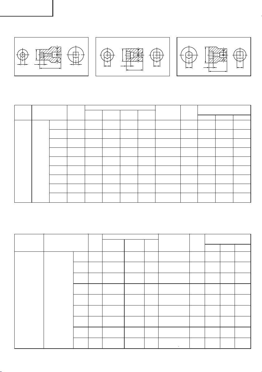
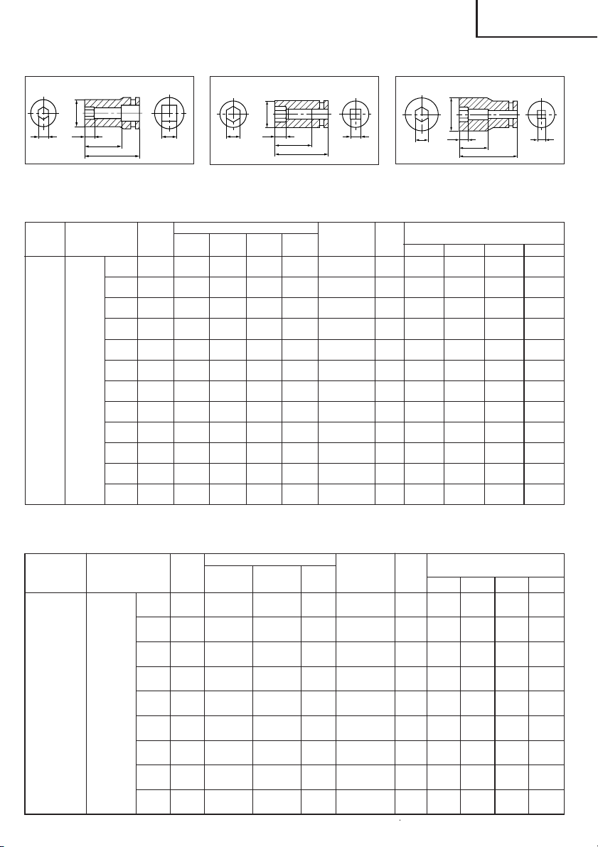
2. Sockets
Form B Form C
ØF
L1
H S
L
<For WR12DM>
Square
head drive
dimensions S
1/2"
(12.7 mm) Socket
Part Name Code No.
10 mm 944291 M6
12 mm 873632 M8 W5/16"
13 mm 873539 M8
Hexagonal
14 mm 873540 M10
17 mm 873536 M10 M12 W3/8"
19 mm 873624 M12 M14 W7/16"
21 mm 873626 W1/2"
22 mm 873627 M12 M14 M16
24 mm 873629 M16 M18
High ISO ISO Inch
tension
<For WR9DM>
Square head
drive dimen-
sions S
3/8"
(9.5 mm)
24
Part Name
Hexagonal
Socket
Code
No.
8 mm 996125
10 mm 996126
12 mm 996127
13 mm 996128
14 mm 996129
16 mm 996130
17 mm 996131
18 mm 996132
19 mm 996133
ØF
L1
H S
L
Table 4
Suitable Bolt Diameter
(ordinary)
(small) bolts
Table 5
Suitable Bolt Diameter
ISO ISO Inch
(ordinary) (small) bolts
M5 (3/16")
M6 (3/4")
M8 (5/16") W5/16"
M8 (5/16")
M10 (3/8")
M10 (3/8")
M10 (3/8")
M12 (15/32")
M12 (15/32")
M12 (15/32")
Form D
Hexagonal
width across Form
flats H
25/64"
(10 mm) (40 mm) (8 mm) (18 mm)
15/32"
(12 mm) (40 mm) (8 mm) (20 mm)
33/64"
(13 mm) (40 mm) (9 mm) (25 mm)
9/16"
(14 mm) (40 mm) (9 mm) (25 mm)
11/16"
(17 mm) (32 mm) (8 mm) (28 mm)
3/4"
(19 mm) (34 mm) (9 mm) (28 mm)
13/16"
(21 mm) (36 mm) (10 mm) (32 mm)
7/8"
(22 mm) (40 mm) (14 mm) (35 mm)
15/16"
(24 mm) (40 mm) (15 mm) (38 mm)
Hexagonal
width across
flats H
5/16" (8 mm) B
3/8" (10 mm) B
15/32" (12 mm) C
1/2" (13 mm) B
9/16" (14 mm) B
5/8" (16 mm) D
W3/8" 21/32" (17 mm) D
23/32" (18 mm) D
W7/16" 3/4" (19 mm) D
LL1øF
1-9/16" 5/16" 11/16"
B
1-9/16" 5/16" 25/32"
B
1-9/16" 11/32" 1"
B
1-9/16" 11/32" 1"
B
1-1/4" 5/16" 1-3/32"
C
1-11/32" 11/32" 1-3/32"
C
1-13/32" 3/8" 1-1/4"
D
1-9/16" 9/16" 1-3/8"
D
1-9/16" 9/16" 1-1/2"
D
Form
LL1øF
1-5/16" 3/16" 1/2"
(33 mm) (5 mm) (13 mm)
1-5/16" 1/4" 5/8"
(33 mm) (6 mm) (16 mm)
1-5/16" 9/32" 3/4"
(33 mm) (7 mm) (19 mm)
1-5/16" 5/16" 25/32"
(33 mm) (8 mm) (20 mm)
1-5/16" 5/16" 13/16"
(33 mm) (8 mm) (21 mm)
1-5/16" 11/32" 15/16"
(33 mm) (9 mm) (24 mm)
1-5/16" 3/8" 1"
(33 mm) (10 mm) (25 mm)
1-5/16" 3/8" 1-1/32"
(33 mm) (10 mm) (26 mm)
1-5/16" 15/32" 1-1/16"
(33 mm) (12 mm)
Main Socket
Dimensions
Main Socket
Dimensions
(27.5 mm)
3. Long Socket
Form B Form C
English
Form D
ØF
L1
H
L2
<For WR12DM>
Square
head drive
dimensions S
1/2" Long
(12.7 mm)
Part Name
12 mm 955138 M8 W5/16"
13 mm 955139 M8
14 mm 955140 M10
17 mm 955141 M10 M12 W3/8"
17 mm 955149 M10 M12 W3/8"
19 mm 955142 M12 M14 W7/16"
Socket
19 mm 955150 M12 M14 W7/16"
21 mm 955143 W1/2"
21 mm 955151 W1/2"
21 mm 991480 W1/2"
22 mm 955144 M12 M14 M16
24 mm 955146 M16 M18
ØF
L1
L
S
H S
L2
L
ØF
L1
H
L2
L
S
Table 6
Code
No.
Suitable Bolt Diameter
High ISO ISO Inch
tension
(ordinary)
(small) bolts
Hexagonal
width across
flats H
15/32"
(12 mm) (52 mm) (20 mm) (34 mm) (20 mm)
33/64"
(13 mm) (52 mm) (20 mm) (34 mm)
(14 mm) (52 mm) (20 mm) (34 mm) (22 mm)
11/16"
(17 mm) (52 mm) (24 mm) (34 mm) (25 mm)
11/16"
(17 mm) (75 mm) (24 mm) (57 mm) (25 mm)
(19 mm) (52 mm) (24 mm) (34 mm) (28 mm)
(19 mm) (75 mm) (24 mm) (57 mm) (28 mm)
13/16"
(21 mm) (52 mm) (24 mm) (34 mm) (31 mm)
13/16"
(21 mm) (75 mm) (24 mm) (57 mm) (31 mm)
13/16"
(21 mm)
(22 mm) (52 mm) (24 mm) (34 mm)
15/16"
(24 mm) (52 mm) (25 mm) (34 mm)
9/16"
3/4"
3/4"
7/8"
Form
2-3/64" 25/32" 1-11/32" 25/32"
B
2-3/64" 25/32" 1-11/32" 53/64"
B
2-3/64" 25/32" 1-11/32" 7/8"
B
2-3/64" 15/16" 1-11/32" 1"
B
2-15/16" 15/16" 2-1/4" 1"
B
2-3/64" 15/16" 1/11/32" 1-3/32"
B
2-15/16" 15/16" 2-1/4" 1-3/32"
B
2-3/64" 15/16" 1-11/32" 1-7/32"
D
2-15/16" 15/16" 2-1/4" 1-7/32"
D
4-15/16" 15/16" 4-7/32" 1-7/32"
D
(125 mm)
2-3/64" 15/16" 1-11/32" 1-9/32"
D
2-3/64" 63/64" 1-11/32" 1-11/32"
D
Main Socket
Dimensions
LL1L2øF
(21-5 mm)
(24 mm)
(107 mm)
(31 mm)
(32.5 mm)
(34 mm)
<For WR9DM>
Square head
drive dimen-
sions S
3/8"
(9.5 mm)
Part Name ISO ISO Inch
Long
Socket
Table 7
Code
8 mm 996134 M5 (3/16") 5/16" (8 mm) B
10 mm 996135 M6 (1/4") 3/8" (10 mm) B
12 mm 996136 M8 (5/16") W5/16"
13 mm 996137 M8 (5/16") 1/2" (13 mm) B
14 mm 996138 M10 (3/8")
16 mm 996139
17 mm 996140
18 mm 996141
19 mm 996142
Suitable Bolt Diameter
No.
(ordinary) (small) bolts
M10 (3/8")
M10 (3/8")
M12 (15/32")
M12 (15/32")
M12 (15/32")
W3/8"
W7/16"
Hexagonal
width across
flats H
15/32" (12 mm)
9/16" (14 mm)
5/8" (16 mm) D
21/32" (17 mm)
23/32" (18 mm)
3/4" (19 mm)
Form
Main Socket
Dimensions
LL1L2øF
2-3/8" 15/32" 1-7/8" 1/2"
(60 mm) (12 mm) (48 mm) (13 mm)
2-3/8" 15/32" 1-7/8" 5/8"
(60 mm) (12 mm) (48 mm) (16 mm)
2-3/8" 9/16" 1-7/8" 23/32"
C
(60 mm) (14 mm) (48 mm) (18.4 mm)
2-3/8" 9/16" 1-7/8" 3/4"
(60 mm) (14 mm) (48 mm) (18.9 mm)
2-3/8" 19/32" 1-7/8" 49/64"
B
(60 mm) (15 mm) (48 mm) (19.5 mm)
2-3/8" 19/32" 1-7/8" 15/16"
(60 mm) (15 mm) (48 mm) (24 mm)
2-3/8" 19/32" 1-7/8" 1"
D
(60 mm) (15 mm) (48 mm) (25 mm)
2-3/8" 5/8" 1-7/8" 1-1/32"
D
(60 mm) (16 mm) (48 mm) (26 mm)
2-3/8" 21/32" 1-7/8" 1-1/16"
D
(60 mm) (17 mm) (48 mm) (27.5 mm)
25
English
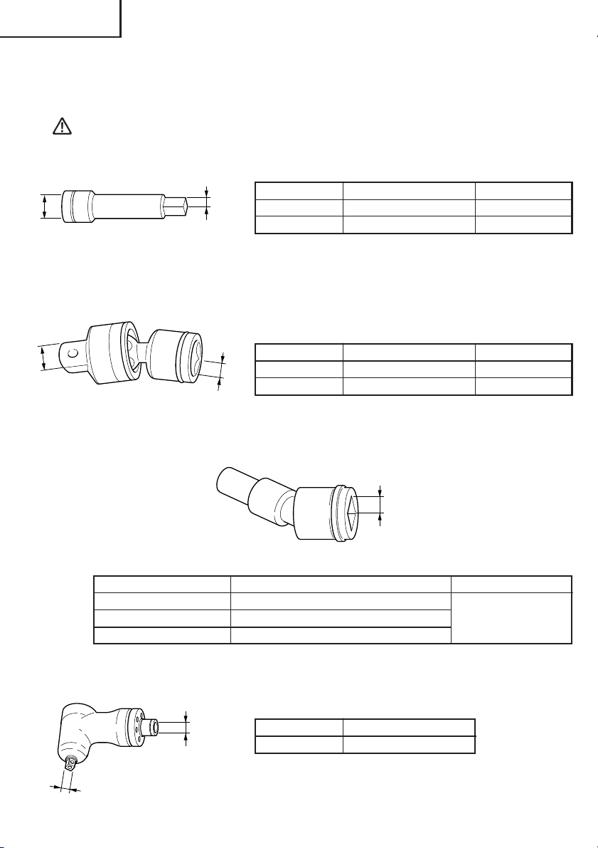
4. Extension bar: (WR12DM, WR9DM)
The extension bar is convenient for working in very restricted spaces or when the socket
provided cannot reach the bolt to be tightened.
CAUTION
When the extension bar is used, the tightening torque is reduced slightly compared with
the ordinary socket.
s
B
873633 1/2" (12.7 mm) WR12DM
996143 3/8" (9.5 mm) WR9DM
Fig. 23
5. Universal joint: (WR12DM, WR9DM)
The universal joint is convenient for impacting nuts when there is an angle between the
socket and wrench, or when working in a very narrow space.
Code No. dimention B, S Model
B
S
Code No. dimention B, S Model
992610 1/2" (12.7 mm) WR12DM
996147 3/8" (9.5 mm) WR9DM
Fig. 24
6. Duct Socket: (WR12DM)
This is used for tightening bolts and nuts on flange sections of air conditioners, type
ducts, etc.
S
Fig. 25
Code No. Hexagonal width across flats Dimention S
993658 15/32" (12 mm)
992613 1/2" (13 mm)
992615 9/16" (14 mm)
1/2"
(12, 7 mm)
7. Corner attachment (Model EW-14R) (WR12DM)
Use this attachment only when the machine is applied to the nut or bolt at the right angle.
S
Model dimention B, S
EW-14R 1/2" (12.7 mm)
B
Fig. 26
26
English
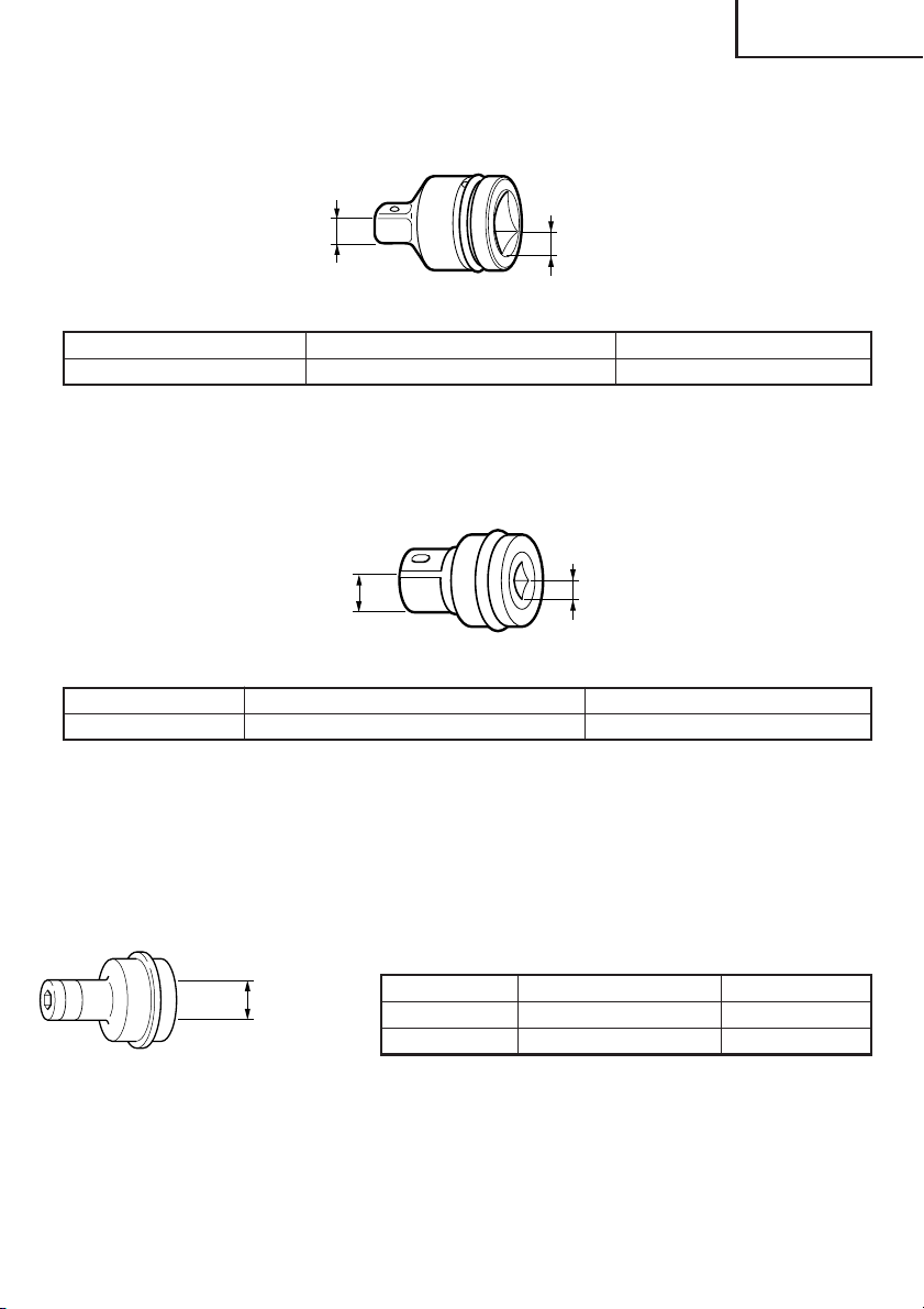
8. 9.5 mm adapter: (WR12DM)
Use this adapter when using the socket that has a square-head-drive dimensions of 9.5
mm.
B
S
Fig. 27
Code No. dimention B dimention S
317383 3/8" (9.5 mm) 1/2" (12.7 mm)
9. 1/2" (12.7 mm) Square adaptor: (WR9DM)
This is used when using a socket with square hole dimensions of 1/2" (12.7 mm).
B
S
Fig. 28
Code No. dimention B dimention S
996145 1/2" (12.7 mm) 3/8" (9.5 mm)
10. Bit adaptor: (WR12DM, WR9DM)
This is used for tightening small screws (M6).
NOTE
This adaptor is set only on the anvil (drive angle) of the main unit.
Fig. 29
S
Code No. dimention S Model
991476 1/2" (12.7 mm) WR12DM
996144 3/8" (9.5 mm) WR9DM
27

English
䢇 Applicable plus driver bit
Bit No. L Code No.
No. 2
No. 3
L
Bit No.
5/8"
(16 mm)
1/4" (6.35 mm)
Fig. 30
1 – 3/4" (45 mm) 955229
2 – 3/4" (70 mm) 955654
1 – 3/4" (45 mm) 955230
2 – 3/4" (70 mm) 955655
NOTE
Specifications are subject to change without any obligaiton on the part of the HITACHI.
28

Français
INFORMATIONS IMPORTANTES DE SÉCURITÉ
Lire et comprendre toutes les précautions de sécurité, les avertissements et les instructions
de fonctionnement dans ce mode d’emploi avant d’utiliser ou d’entretenir cet outil motorisé.
La plupart des accidents causés lors de l’utilisation ou de l’entretien de l’outil motorisé
proviennent d’un non respect des règles ou précautions de base de sécurité. Un accident
peut la plupart du temps être évité si l’on reconnaît une situation de danger potentiel avant
qu’elle ne se produise, et en observant les procédures de sécurité appropriées.
Les précautions de base de sécurité sont mises en évidence dans la section “SECURITE” de
ce mode d’emploi et dans les sections qui contiennent les instructions de fonctionnement
et d’entretien.
Les dangers qui doivent être évités pour prévenir des blessures corporelles ou un
endommagement de la machine sont identifiés par AVERTISSEMENTS sur l’outil motorisé
et dans ce mode d’emploi.
NE JAMAIS utiliser cet outil motorisé d’une manière qui n’est pas spécifiquement
recommandée par HITACHI.
SIGNIFICATION DES MOTS D’AVERTISSEMENT
AVERTISSEMENT indique des situations potentiellement dangereuses qui, si elles sont
ignorées, pourraient entraîner la mort ou de sérieuses blessures.
PRECAUTION indique des situations dangereuses potentilles qui, si elles ne sont pas
évitées, peuvent entraîner de mineures et légères blessures ou endommager la machine.
REMARQUE met en relief des informations essentielles.
29

Français
SECURITE
REGLES GENERALE DE SECURITE – POUR TOUS LES OUTILS
FONCTIONNANT SUR BATTERIE
AVERTISSEMENT: Lire et coxmprendre toutes les instructions.
Un non respect de toutes les instructions ci-dessous peut entraîner
une électrocution, un incendie et/ou de sérieuses blessures
personnelles.
CONSERVER CES INSTRUCTIONS
1. Zone de travail
(1) Garder la zone de travail propre et bien éclairée. Les établis mal rangés et les zones
sombres invitent aux accidents.
(2) Ne pas utiliser les outils motorisés dans une atmosphère explosive, telle qu’en
présence de liquides inflammables, de gaz ou de poussières. Les outils motorisés
créent des étincelles qui risquent d’enflammer la poussière ou les vapeurs.
(3) Tenir les spectateurs, les enfants et les visiteurs éloignés, lors de l’utilisation de
l’outil motorisé. Une distraction peut faire perdre le contrôle de la machine.
2. Sécurité électrique
(1) Un outil motorisé à batterie avec batterie intégrée ou batterie séparée ne devra être
rechargé qu’avec le chargeur spécialement conçu pour la batterie. Un chargeur qui
convient pour un type de batterie donné peut présenter un risque de feu s’il est utilisé
avec une autre batterie.
(2) Utiliser l’outil motorisé à batterie exclusivement avec la batterie spécialement
conçue. L’utilisation de toute autre batterie peut présenter un risque de feu.
3. Sécurité personnelle
(1) Rester sur ses gardes, regarder ce que l’on fait et utiliser son sens commun lors de
l’utilisation d’un outil motorisé. Ne pas utiliser un outil en état de fatigue ou sous
l’influence de drogues, d’alcool ou de médicaments. Un moment d’inattention lors de
l’utilisation de l’outil motorisé peut entraîner de sérieuses blessures personnelles.
(2) S’habiller correctement. Ne pas porter des vêtements larges ou des bijoux. Attacher
les cheveux longs. Tenir ses cheveux, vêtements et ses gants éloignés des parties
mobiles. Les vêtements larges, les bijoux et les cheveux longs peuvent se prendre
dans les parties mobiles.
(3) Eviter tout démarrage accidentel. S’assurer que le l’interrupteur d’alimentation est
sur la position d’arrêt avant de brancher la machine. Transporter l’appareil avec les
doigts sur l’interrupteur d’alimentation ou brancher un outil avec l’interrupteur sur la
position marche invite aux accidents.
(4) Retirer les clefs d’ajustement ou les commutateurs avant de mettre l’outil sous
tension. Une clef qui est laissée attachée à une partie tournante de l’outil peut
provoquer une blessure personnelle.
(5) Ne pas trop présumer de ses forces. Garder en permanence une position et un
équilibre correct. Une position et un équilibre correct permettent un meilleur contrôle
de l’outil dans des situations inattendues.
(6) Utiliser un équipement de sécurité. Toujours porter des lunettes de protection. Un
masque à poussière, des chaussures de sécurité antidérapantes, un chapeau dur et
des bouchons d’oreille doivent être utilisés dans les conditions appropriées.
30

Français
4. Utilisation de l’outil et entretien
(1) Utiliser un étau ou toutes autres façons de fixer et maintenir la pièce à usiner sur une
plate-forme stable. Tenir la pièce avec la main ou contre son corps est instable et peut
conduire à une perte de contrôle de l’outil.
(2) Ne pas forcer sur l’outil. Utiliser l’outil correct pour l’application souhaitée. L’outil
correct réalisera un meilleur et plus sûr travail dans le domaine pour lequel il a été
conçu.
(3) Ne pas utiliser un outil s’il ne se met pas sous ou hors tension avec un interrupteur.
Un outil qui ne peut pas être commandé avec un interrupteur est dangereux et doit
être réparé.
(4) Débrancher la batterie de l’outil ou mettre l’interrupteur sur la position verrouillée
ou éteinte avant d’effectuer un réglage, de remplacer un accessoire ou de ranger
l’outil. Ces mesures de sécurité préventives réduiront les risques de déclenchement
accidentel de l‘outil.
(5) Ranger les outils inutilisés hors de la portée des enfants et des autres personnes
inexpérimentées. Les outils sont dangereux dans les mains de personnes
inexpérimentées.
(6) Lorsqu’on ne se sert pas de la batterie, l’éloigner des objets métalliques, par exemple
trombones, pièces de monnaie, clous, vis, ou petits objets métalliques qui peuvent
créer une connexion entre deux bornes. Le fait de court-circuiter les bornes entre elles
peut provoquer des étincelles, des brulûres ou un feu.
(7) Conserver les outils avec soin. Garder les outils de coupe aiguisés et propres. Des
outils bien entretenus, avec des lames coupantes aiguisées risquent moins de se
gripper et sont plus faciles à contrôler.
(8) Vérifier les défauts d’alignement ou grippage des parties mobiles, les ruptures des
pièces et toutes les autres conditions qui peuvent affecter le fonctionnement des
outils. En cas de dommage, faire réparer l’outil avant de l’utiliser. Beaucoup
d’accidents sont causés par des outils mal entretenus.
(9) Utiliser uniquement les accessoires recommandés par le fabricant pour le modèle
utilisé. Des accessoires qui peuvent convenir à un outil, peuvent devenir dangereux
lorsqu’ils sont utilisés avec un autre outil.
5. Réparation
(1) La réparation de l’outil ne doit être réalisée uniquement par un réparateur qualifié.
Une réparation ou un entretien réalisé par un personnel non qualifié peut entraîner
des risques de blessures.
(2) Lors de la réparation d’un outil, utiliser uniquement des pièces de rechange identiques.
Suivre les instructions de la section d’entretien de ce mode d’emploi. L’utilisation de
pièces non autorisées ou un non respect des instructions d’entretien peut créer un
risque d’électrocution ou de blessures.
AVERTISSEMENT:
La poussière résultant d'un ponçage, d'un sciage, d'un meulage, d'un perçage ou
de toute autre activité de construction renferme des produits chimiques qui sont
connus par l'Etat de Californie pour causer des cancers, des défauts de naissance
et autres anomalies de reproduction. Nous énumérons ci-dessus certains de ces
produits chimiques:
● Plomb des peintres à base de plomb,
● Silice cristalline des briques et du ciment et autres matériaux de maçonnerie, et
● Arsenic et chrome du bois d'oeuvre traité chimiquement.
Le risque d'exposition à ces substances varie en fonction de la fréquence d'exécution
de ce genre de travail. Pour réduire l'exposition à ces produits chimiques, travailler
dans un lieu bien ventilé, et porter un équipement de protection agréé, par exemple
un masque anti-poussière spécialement conçu pour filter les particules microscopiques.
31

Français
REGLES DE SECURITE SPECIFIQUES
1. Tenir les outils par les surfaces de grippage lors de la réalisation d’opération où l’outil
de coupe risque d’entrer en contact avec des câbles cachés. Un contact avec un fil “sous
tension” mettra les parties métalliques de l’outil “sous tension” et électrocutera
l’utilisateur.
2. Ne jamais toucher les parties mobiles.
Ne jamais placer ses mains, ses doigts ou toute autre partie de son corps près des parties
mobiles de l’outil.
3. Ne jamais utiliser l’outil sans que tous les dispositifs de sécurité ne soient en place.
Ne jamais faire fonctionner cet outil sans que tous les dispositifs et caractéristiques de
sécurité ne soient en place et en état de fonctionnement. Si un entretien ou une réparation
nécessite le retrait d’un dispositif ou d’une caractéristique de sécurité, s’assurer de bien
remettre en place le dispositif ou la caractéristique de sécurité avant de recommencer à
utiliser l’outil.
4. Utiliser l’outil correct
Ne pas forcer sur un petit outil ou accessoire pour faire le travail d’un outil de grande
puissance. Ne pas utiliser un outil pour un usage pour lequel il n’a pas été prévu: par
exemple, ne pas utiliser une scie circulaire pour couper des branches d’arbre ou des
bûches.
5. Ne jamais utiliser un outil motorisé pour des applications autres que celles spécifiées.
Ne jamais utiliser un outil motorisé pour des applications autres que celles spécifiées
dans le mode d’emploi.
6. Manipuler l’outil correctement
Utiliser l’outil de la façon indiquée dans ce mode d’emploi. Ne pas laisser tomber ou
lancer l’outil. Ne jamais permettre que l’outil soit utilisé par des enfants, des personnes
non familiarisées avec son fonctionnement ou un personnel non autorisé.
7. Définitions pour les symboles
V ............. volts
--- ............ courant continu
no........... vitesse à vide
---/min .... rotations ou mouvements de va-et-vient par minute
8. Maintenir toutes les vis, tous les boulons et les couvercles fermement en place.
Maintenir toutes les vis, tous les boulons et les couvercles fermement montés. Vérifier
leurs conditions périodiquement.
9. Ne pas utiliser les outils motorisés si le revêtement de plastique ou la poignée est fendu.
Des fentes dans le revêtement ou la poignée peuvent entraîner une électrocution. De tels
outils ne doivent pas être utilisés avant d’être réparé.
10. Les lames et les accessoires doivent être fermement montés sur l’outil.
Eviter les blessures potentielles personnelles et aux autres. Les lames, les instruments
de coupe et les accessoires qui ont été montés sur l’outil doivent être fixés et serrés
fermement.
11. Ne jamais utiliser un outil défectueux ou qui fonctionne anormalement.
Si l’outil n’a pas l’air de fonctionner normalement, fait des bruits étranges ou sans cela
paraît défectueux, arrêter de l’utiliser immédiatement et le faire réparer par un centre de
service Hitachi autorisé.
32

Français
12. Manipuler l’outil motorisé avec précaution.
Si un outil motorisé tombe ou frappe un matériau dur accidentellement, il risque d’être
déformé, fendu ou endommagé.
13. Ne pas essuyer les parties en plastique avec du solvant.
Les solvants comme l’essence, les diluants, la benzine, le tétrachlorure de carbone et
l’alcool peuvent endommager et fissurer les parties en plastique. Ne pas les essuyer avec
de tels solvants.
Essuyer les parties en plastique avec un chiffon doux légèrement imbibé d’une solution
d’eau savonneuse et sécher minutieusement.
CONSIGNES DE SÉCURITÉ IMPORTANTES POUR L’UTILISATION
DU CLÉ À CHOC À BATTERIE
AVERTISSEMENT:Une utilisation incorrecte ou sans sécurité de la clé à choc à
batterie risque d’entraîner la mort ou des blessures graves.
Pour éviter ces risques, observer les consignes de sécurité
élémentaires suivantes :
1. Ne jamais utiliser ce manche de poignée pour des applications autres que celles
spécifiées dans ce manuel.
2. Lors d’un travail en hauteur, toujours vérifier qu’il n’y a personne dessous avant de
commencer à travailler.
3. Toujours porter des lunettes et des protections anti-bruit pendant le travail.
4. Vérifier qu’il n’y a pas de fissure sur la douille.
5. Fixer la douille hexagonale solidement sur le piton. Si la douille hexagonale n’est pas
fixée assez solidement, elle risque de tomber et de provoquer un accident. Pour
l’accessoire de douille hexagonale, voir “UTILISATION”, page 42.
6. Vérifier le couple de serrage à l’aide d’une clé dynamométrique avant l’utilisation, de
façon à s’assurer que le couple de serrage sera correct.
7. Si l’on utilise un joint universel, ne pas faire fonctionner l’outil à vide. Cela serait
dangereux. Si la section de la douille tourne autour du joint, cela risque de provoquer des
blessures aux mains et sur le corps, ou sous l’effet des vibrations intenses qui en
résulteraient, l’utilisateur risque de laisser tomber l’outil.
8. Veiller à ce qu’aucun corps étranger ne bloque les orifices situés des deux côtés de la
poignée. Par ailleurs, ne pas boucher les orifices avec du ruban adhésif. Ces orifices
remplissent une fonction importante.
33

Français
CONSIGNES DE SÉCURITÉ IMPORTANTES POUR LE CHARGEUR DE
BATTERIE
1. Ce manuel renferme des consignes de sécurité et d’utilisation importantes pour le
chargeur de batterie modèle UC14YF2.
2. Avant d’utiliser le chargeur de batterie, lire toutes les étiquettes d’instruction et de
précaution apposées sur (1) le chargeur de batterie, (2) la batterie, et (3) le produit utilisant
la batterie.
3. Pour réduire tout risque de blessure, NE recharger QUE les batteries rechargeables
HITACHI utilisées dans le modèle series EB7, EB9, EB12 et EB14. Les autres types de
batterie pourraient exploser et provoquer des blessures ou des dommages.
4. Ne pas exposer le chargeur à la pluie ni à la neige.
5. L’utilisation d’un accessoire non recommandé ou non vendu par le fabricant du chargeur
de batterie risque de provoquer un feu, une décharge électrique ou des blessures.
6. Pour réduire tout risque de dommage de la fiche et du cordon électrique, débrancher le
cordon du chargeur en tirant sur la fiche.
7. Vérifier que le cordon est placé de façon que personne ne puisse marcher dessus, se
prendre les pieds dedans, ni l’endommager ou le soumettre à des contraintes.
8. Ne pas utiliser de cordon de rallonge si cela n’est pas absolument nécessaire. L’utilisation
d’un cordon de rallonge incorrect pourrait entraîner un feu ou une décharge électrique.
Si l’on doit utiliser un cordon de rallonge, s’assurer que :
a. Les broches de la rallonge ont les mêmes numéro, taille et forme que celles de la fiche
du chargeur ;
b. Le cordon de rallonge est correctement raccordé et en bon état électrique ;
c. Le calibre du fil doit être au moins suffisant pour l’intensité nominale CA (ampères)
du chargeur de batterie spécifiées dans le tableau ci-dessous.
Tableau 1
CALIBRE MINIMUM RECOMMANDÉ POUR LES CORDONS DE RALLONGE
DES CHARGEURS DE BATTERIE
Intensité nominale d’entrée CA (ampères)*
Egal ou mais non Longueur de cordon en pieds (mètres)
supérieur à inférieur à 25 (7.5) 50 (15) 100 (30) 150 (45)
0 2 18 18 18 16
2 3 18 18 16 14
3 4 18 18 16 14
* Si l’intensité nominale d’entrée du chargeur de batterie est donnée en watts et non en
ampères, calculer la capacité en ampères correspondante en divisant la capacité en
ampères par la capacité de tension, par exemple :
1250 watts
125 volts
34
= 10 ampères
Calibre du cordon

Français
9. Ne pas utiliser le chargeur si son cordon ou sa fiche sont endommagés - Le remplacer
immédiatement.
10. Ne pas utiliser le chargeur s’il a reçu un coup, s’il est tombé ou endommagé de toute autre
manière. L’apporter à un réparateur qualifié.
11. Ne pas démonter le chargeur ni le produit qui reçoit la batterie ; si un entretien ou des
réparations sont nécessaires, les apporter à un réparateur qualifié. Un remontage
incorrect pourrait provoquer une décharge électrique ou un feu.
12. Pour réduire tout risque de décharge électrique, débrancher le chargeur de la prise
secteur avant tout entretien ou nettoyage. Il ne suffit pas de sortir la batterie.
CONSIGNES DE SÉCURITÉ IMPORTANTES POUR L’UTILISATION
DE LA BATTERIE ET DU CHARGEUR DE BATTERIE
Pour pouvoir utiliser la clé à choc à batterie, il faudra recharger la batterie. Avant d’utiliser
le chargeur de batterie modèle UC14YF2, bien lire attentivement toutes les consignes et les
avertissements signalés sur le chargeur, sur la batterie ou dans ce manuel.
BIEN NOTER : UTILISER EXCLUSIVEMENT DES BATTERIES HITACHI DES SERIES EB7, EB9
EB12, ET EB14. LES AUTRES TYPES DE BATTERIE POURRAIENT EXPLOSER OU PROVOQUER DES BLESSURES.
Pour éviter tout risque de blessure, observer les consignes suivantes :
AVERTISSEMENT:Une utilisation incorrecte de la batterie ou du chargeur de
batterie risque de provoquer des blessures. Pour éviter tout
risque de blessure :
1. NE JAMAIS démonter la batterie.
2. NE JAMAIS jeter la batterie au feu, même si elle est endommagée ou complètement
usée. La batterie risque d’exploser au feu.
3. NE JAMAIS court-circuiter la batterie.
4. NE JAMAIS insérer d’objets dans les ouïes d’aération du chargeur. Il pourrait en
résulter un choc électrique ou des dommages du chargeur.
5. NE JAMAIS effectuer la recharge à l’extérieur. Eloigner la batterie des rayons directs
du soleil et utiliser exclusivement dans des endroits à faible humidité et
bien aérés.
6. NE JAMAIS effectuer la recharge si la température est inférieure à 32°F (0°C) ou
supérieure à 104°F (40°C).
7. NE JAMAIS raccorder deux chargeurs de batterie ensemble.
8. NE JAMAIS insérer de corps étrangers dans l’orifice de la batterie ou du chargeur de
batterie.
9. NE JAMAIS utiliser de transformateur-élévateur pour la recharge.
10. NE JAMAIS utiliser de générateur de moteur ni d’alimentation CC pour la recharge.
11. NE JAMAIS ranger la batterie ni le chargeur de batterie dans un lieu où la température
peut atteindre ou dépasser 104°F (40°C).
35

Français
12. TOUJOURS alimenter le chargeur sur une prise secteur domestique standard (120
volts). L’utilisation du chargeur à une autre tension peut entraîner une
surchauffe et endommager le chargeur.
13. TOUJOURS attendre au moins 15 minutes entre deux recharges pour éviter toute
surchauffe du chargeur.
14. TOUJOURS débrancher le cordon d’alimentation de la prise secteur lorsqu’on ne se
sert pas du chargeur.
CONSERVER CES INSTRUCTIONS
ET
LES METTRE A LA DISPOSITION
DES AUTRES UTILISATEURS
ET
PROPRIETAIRES DE CET OUTIL!
36

Français
DESCRIPTION FONCTIONNELLE
REMARQUE:
Les informations contenues dans ce mode d’emploi sont conçues pour assister l’utilisateur
dans une utilisation sans danger et un entretien de l’outil motorisé.
NE JAMAIS utiliser ni entreprendre une révision de l’outil sans avoir d’abord lu et
compris toutes les instructions de sécurité contenues dans ce manuel.
Certaines illustrations dans ce mode d’emploi peuvent montrer des détails ou des
accessoires différents de ceux de l’outil motorisé utilisé.
MODELE
WR 12DM: avec chargeur (UC14YF2) et coffret.
WR 9DM: avec chargeur (UC14YF2) et coffret.
NOM DES PARTIES
1. Clé à choc à batterie
Carter
Plaque signalétique
Events d'aération
䡬 Batterie
Plaque
signalétique
Poignée
WR12DM: 1/2" (12,7 mm)
WR9DM: 3/8" (9,5 mm)
Orifice de
prise
Taquet
EB1220BL EB9B
Déclencheur
Plaque
signalétique
Fig. 1
Boutonpoussoir
Crochet
pratique
Batterie
Orifice de
prise
Taquet
37

Français
2. Chargeur de batterie (UC14YF2)
Lampe témoin
Cordon
Orifice d‘installation de la batterie
Plaque de précaution
Corps
Fig. 2
Plaque signalétique
SPECIFICATIONS
1. Clé à choc à batterie
Modèle
Moteur Moteur CC
Vitesse à vide 0 – 2300/min
Entraînement Carré, 3/8" (9,5 mm) Carré, 1/2" (12,7 mm)
Capacité 1/4" – 9/16" (M6 – M14) 1/4" – 5/8" (M6 – M16)
(Boulon ordinaire) (Boulon ordinaire)
1/4" – 3/8" (M6 – M10) 1/4" – 15/32" (M6 – M12)
(Boulon hatement (Boulon hatement
extensible) extensible)
Tightening torque Maximum 780 in-lbs Maximum 1330 in-lbs
(88,2 N·m, 900 kgf·m) (150 N·m, 1530 kgf·m)
Serrage de 15/32" (M12) avec Serrage de 5/8" (M16) F10T,
boulon à haute résistance, avec recharge complète à
avec recharge complète à une température de 20°C.
une température de 20°C. Temps de serrage: 3 secondes
Temps de serrage: 3 secondes
Batterie EB9B (2,0 Ah) EB1220BL (2,0 Ah)
rechargeable Batterie Ni-Cd, 9,6 V Batterie Ni-Cd, 12 V
Fréquence de charge et Fréquence de charge et
décharge: environ 1000 décharge: environ 1000
Poids 3,0 lbs (1,4 kg) 3,5 lbs (1,6 kg)
WR9DM WR12DM
(9,6V) (12V)
2. Chargeur de batterie (UC14YF2)
Source d’alimentation d’entrée Monophasée : CA 120 V 60 Hz
Durée de recharge Environ 60 min (à une température de 68°F (20°C))
Chargeur
Poids 2,9 lbs (1,3 kg)
38
Tension de charge ....................... CC 7,2–14,4 V
Courant de charge ....................... CC 1,9 A

Français
ASSEMBLAGE ET FONCTIONNEMENT
UTILISATIONS
䡬 Pour le serrage et le desserrage de tous types de boulons et d’écrous utilistés pour la
consolidation de stuctures.
MÉTHODE DE RETRAIT ET D’INSTALLATION DE LA BATTERIE
䡬 Installation de la batterie
Aligner la batterie sur la fente de la poignée
Poignée
Taquet
Insérer
Batterie
rechargeable
Tirer
Fig. 3
de l’outil et la glisser à l’intérieur.
Toujours insérer la batterie à fond, jusqu’à
ce qu’elle se bloque avec un petit déclic.
Sinon, elle risque de tomber accidentellement de l’outil et de blesser l’opérateur ou
d’autres personnes alentour. (Fig. 3)
䡬 Retrait de la batterie
Sortir la batterie de la poignée de l’outil tout
en appuyant sur les taquet de chaque côté
de la batterie. (Fig. 3)
MÉTHODE DE RECHARGE
REMARQUE:
Avant de brancher le chargeur dans la prise, vérifier les points suivants.
䡬 La tension de la source d’alimentation est indiquée sur la plaque signalétique.
䡬 Le cordon n’est pas endommagé.
AVERTISSEMENT:Ne pas effectuer de recharge à une tension supérieure à la
tension indiquée sur la plaque signalétique. Cela brûlerait le
chargeur.
1. Brancher la fiche du chargeur de batterie
Batterie
rechargeable
d
Fig. 4
Orifice
d’installation
de la batterie
Lampe
pilote
dans la prise.
Quand la fiche du chargeur de batterie est
branchée dans la prise, le voyant de recharge clignote lentement en rouge. (A
intervalles d’une seconde)
AVERTISSEMENT:
Ne pas utiliser le cordon
électrique s’il est
endommagé. Le faire
réparer immédiatement.
39

Français
2. Insérer la batterie dans le chargeur de batterie.
Insérer la batterie dans le chargeur de batterie comme indiqué à la Fig. 4. Bien s’assurer
qu’elle touche le fond du chargeur de batterie.
PRECAUTION:
Si la batterie est insérée à l’envers, non seulement la recharge sera impossible, mais cela
peut également provoquer des problèmes dans le chargeur, par exemple une borne de
recharge déformée.
3. Recharge
Quand la batterie est raccordée au chargeur de batterie, la recharge commence et la
lampe témoin s’allume en rouge. (Voir le Tableau 2)
REMARQUE:
Si la lampe témoin clignote en rouge, débrancher la fiche de la prise et vérifier si la
batterie est insérée correctement.
Quand la batterie est rechargée à fond, la lampe témoin clignote lentement en rouge. (A
intervalles d’une seconde) (Voir le Tableau 2.)
(1) Indication de la lampe témoin
Les indications de la lampe témoin sont expliquées dans le Tableau 2, selon la condition
du chargeur ou de la batterie rechargeable.
Tableau 2
Indications de la lampe témoin
Avant la
recharge
Pendant la
recharge
Recharge
terminée
Recharge
impossible
Recharge
impossible
Clignote
(ROUGE)
S’allume
(ROUGE)
Clignote
(ROUGE)
Scintille
(ROUGE)
S’allume
(VERTE)
S’allume pendant 0,5 seconde.
Ne s’allume pas pendant 0,5 seconde.
(Eteint pendant 0,5 seconde)
S’allume sans interruption
S’allume pendant 0,5 seconde.
Ne s’allume pas pendant 0,5 seconde.
(Eteint pendant 0,5 seconde)
S’allume pendant 0,1 seconde.
Ne s’allume pas pendant 0,1 seconde.
(Eteint pendant 0,1 seconde)
S’allume sans interruption
Anomalie de la batterie ou du
chargeur
La température de la batterie est
élevée et la recharge est impossible.
(2) Température admissible d’une batterie rechargeable
La température admissible des batteries rechargeables est indiquée dans le tableau cidessous, et les batteries qui ont chauffé devront être laissées à refroidir pendant quelque
temps avant de pouvoir être rechargées.
40

Tableau 3 Recharge de batteries qui ont chauffé
Français
Batteries rechargeables
EB9B, EB1220BL
(3) Durée de recharge (A 68°F (20°C))
Environ 60 minutes
REMARQUE:
La durée de recharge peut varier en fonction de la température et de la tension de la
source d’alimentation.
Température à laquelle la batterie peut être rechargée
23°F—140°F
(–5°C—60°C)
4. Débrancher le chargeur de batterie de la prise.
PRECAUTION:
Ne pas débrancher la fiche de la prise en tirant sur le cordon.
Pour éviter tout dommage lorsqu’on débranche la fiche de la prise, bien tenir la fiche
proprement dite.
5. Retirer la batterie du chargeur de batterie.
Sortir la batterie du chargeur tout en la soutenant de la main.
PRECAUTION:
● Si le chargeur a fonctionné pendant longtemps de suite, il sera chaud, ce qui risque de
provoquer des pannes. Lorsque la recharge est terminée, laisser le chargeur refroidir
pendant environ 15 secondes avant de passer à la recharge suivante.
● Si l’on recharge la batterie lorsqu’elle est chaude, soit parce qu’elle vient de fonctionner,
soit parce qu’elle est en plein soleil, il se peut que la lampe témoin s’allume en vert.
La batterie ne se rechargera pas. Dans ce cas, laisser la batterie refroidir avant de la
recharger.
● Si la lampe témoin clignote rapidement en rouge (à intervalles de 0,2 seconde), vérifier
s’il y a des corps étrangers dans l’orifice d’installation de la batterie du chargeur, et les
enlever le cas échéant. S’il n’y a pas de corps étrangers, il s’agit probablement d’une
anomalie de la batterie ou du chargeur. Les porter au service après-vente agréé.
● Etant donné qu’il faut environ 3 secondes au micro ordinateur intégré pour confirmer
l’extraction de la batterie in cours de chargement, attendre 3 secondes au minimum
avent de la réinsérer pour continuer le chargement. Si la batterie est réinsérée dans les
3 seconds, elle reque de ne pas être correctement rechargée.
En ce qui concerne le courant de décharge d’une batterie neuve
Etant donnée que les substances chimiques internes sont restées inactives dans le cas
des batteries neuves ou des batteries qui sont restées longtemps inutilisées, le courant
de décharge risque d’être très faible lors des première et deuxième utilisations. Ce
phénomène est temporaire et le temps de recharge normal sera rétabli quand les
batteries auront été rechargées 2 ou 3 fois.
41

Français
Comment prolonger la durée de vie des batteries
(1) Recharger les batteries avant qu’elles ne soient complètement épuisées.
Quand la puissance de l’outil utilisé faiblit, l’éteindre et recharger la batterie. Si l’outil
continue d’être utilisé jusqu’à épuisement du courant électrique, la batterie risque d’être
endommagée et sa durée de vie se raccourcira.
(2) Eviter d’effectuer la recharge sous des températures élevées.
Une batterie est toujours chaude immédiatement après son utilisation. Si la batterie est
rechargée immédiatement après utilisation, les substances chimiques internes risquent
de se détériorer et la durée de vie de la batterie se raccourcira. Laisser la batterie refroidir
un moment avant de l’utiliser.
AVANT L’UTILISATION
Vérifier l’aire de travail pour s’assurer qu’il n’y a ni débris ni désordre.
Evacuer toutes les personnes non nécessaires au travail. S’assurer que l’éclairage et la
ventilation sont satisfaisants.
UTILISATION
1. Utilisation du crochet pratique
Le crochet pratique peut se fixer sur le côté droit
ou sur le côté gauche, et son angle peut se régler
sur 5 paliers, entre 0° et 80°.
(1) Ouverture du crochet
(a) Tirer le crochet vers soi dans le sens de la flèche
(A), et le tourner dans le sens de la flèche (B).
(Fig. 5)
(b) L’angle se règle sur 5 paliers (0°, 22°, 40°, 60°,
80°).
Régler l’angle du crochet sur la position
d’utilisation voulue.
(2) Modification de la position du crochet
PRECAUTION:
● Si l’outil tombe, cela risque de provoquer un
mauvais fonctionnement et/ou des dégâts
matériels. Il est recommandé d’utiliser également
des fils métalliques de prévention des chutes, etc.
● Une installation incomplète du crochet peut
entraîner des blessures physiques lors de
l’utilisation.
(a) Tenir fermement le boîtier de l’outil et retirer la
vis à l’aide d’un tournevis pour écrou à fente ou
d’une pièce de monnaie. (Fig. 6)
(b) Retirer le crochet et le ressort. (Fig. 7)
Crochet pratique
Fig. 5
Fig. 6
Ressort
42
Fig. 7

(c) Fixer le crochet et le ressort de l’autre côté et
serrer à fond avec la vis. (Fig. 8)
REMARQUE :
Faire attention à l’orientation du ressort. Installer
le ressort avec le gros diamètre loin de soi. (Fig.
8)
Si l’outil tombe, cela risque de provoquer un
mauvais fonctionnement et/ou des dégâts
matériels. Il est recommandé d’utiliser
également des fils métalliques de prévention
des chutes, etc.
2. Choisir une doulille pouvant s’accjoupler au boulon.
Bein choisir une douille pouvant s’accoupler au
boulon qui doit être serré. Une douille trop grande
non seulement empêhera un bon serrage mais
risque aussi d’endommager la douille ou l’écrou.
Une douille six pans ou carrée usée ou déformée
ne permettra pas un bon serrage pour fixer l’écrou
ou la chabotte, et, en conséquence, ceci se traduira
pas une perte de couple. Veiler à l’usure des trous
de douiles et les remplacer avant que toute usure
excessive soit constatée.
Les tailles de douille et de boulon correspondantes
sont indiquées aux Tableaux 4, 5, 6 et 7. La valeur
numérique de la désignation de douille représente
la distance d'un côté à l'autre (H) de son orifice
hexagonal.
Douille hexagonal
Douille
hexagonal
3. Mise in place d’une douille (Fig. 9, 10)
Aligner le piston, situé dans la partie carrée de
l’enclume, avec l’orifice de la fiche hexagonale.
Ensuite, enfoncer le piston et la fiche hexagonale
dans l’enclume. S’assurer que le piston est
complètement engagé dans l’orifice. Lorsqu’ on
enlève la fiche hexagonale, inverser les démarches.
4. Retrait de la douille
Procéder dans l'ordre inverse de l'installation.
5. Vérifiez si la batterie a été correctement
R
installée.
6. Vérifiez le sens de rotation.
La mèche tourne dans le sens horaire (vu de l’arrière)
quand on appuie sur le côté R du bouton-poussoir.
En appuyant sur le côté L du bouton-poussoir, la
mèche tourne dans le sens anti-horaire. (Voir Fig.
11) (Les repères L et R sont marqués sur le corps.)
Pousser Pousser
Fig. 8
Rainure
Fig. 9
Orifice
Fig. 10
Poussoir
Fig. 11
Français
Gros diamètre dirigé
vers l’extérieur
Chabotte
Piston
Chabotte
L
43

Français
PRECAUTION
Il n’est pas possible de commuter le bouton-poussoir pendant que le tournevis à
percussion fonctionne. Pour commuter le bouton-poussoir, arrêter le tournevis à
percussion, puis régler le bouton-poussoir.
7. Fonctionnement de l’interrupteur
䡬 Quand on tire sur la gâchette de l’interrupteur, l’outil tourne. Quand on relâche la
gâchette, l’outil s’arrête.
䡬 La vitesse de rotation peut être contrôlée en faisant varier la force avec laquelle on appuie
sur la gâchette. Quand on appuie légèrement sur la gâchette, la vitesse est lente, et elle
augmente quand on appuie plus fort.
REMARQUE
La vitesse de rotation de la foreuse peut être contrôlée en faisant varier la force avec
laquelle on appuie sur l‘interrupteur. En appuyant légèrement sur l‘interrupteur, la
vitesse est basse et elle augmente lorsqu‘on appuie plus fort.
8. Serrage et desserrage des boulon
Commencer par sélectionner une douille hexagonale qui convient pour le boulon ou
l’écrou. Puis, monter la douille sur le piton, et saisir l’écrou à serrer avec la douille
hexagonale. Tout en tenant la clé dans l’alignement du boulon, appuyer sur l’interrupteur
pour percuter l’écrou pendant plusieurs secondes.
Si l’écrou n’est pas serré à fond sur le boulon, le boulon risque de tourner en même temps
que l’écrou, empêchant d’obtenir le couple de serrage voulu. Dans ce cas, cesser de
percuter l’écrou et tenir la tête du boulon avec une clé avant de recommencer la
percussion, ou serrer manuellement le boulon et l’écrou pour les empêcher de glisser.
9. Nombre de serrages d’écrous ou de boulon possible (abec une charge (EB14B))
Prière de se référer au tableau ci-dessous pour connaître le nombre de serrages d’écrous
ou de boulon possible avec une seule charge.
<Pour WR12DM> (EB1220BL)
Boulon utilisé Nombre de serrages
5/8" × 2–5/32" (M16 × 55) F10T Boulon Environ 90
<Pour WR9DM> (EB9B)
Boulon utilisé Nombre de serrages
15/32" × 1–3/4" (M12 × 45) Boulon ordinaire Environ 90
Ces valeurs peuvent varier quelque peu selon la température ambiante et le type des piles
employées.
44

Français
PRECAUTIONS D’UTILISATION
1. Repos de l’appareil après un travail continu
Après un travail de serrage de boulons effectué de façon continue, laisser l’outil reposer
pendant environ 15 minutes lors du remplacement de la batterie. La température du
moteur, de la gâchette, etc. augmentera si le travail est repris tout de suite après le
remplacement de la batterie, ce qui risque de provoquer un grillage.
PRECAUTION: Ne pas toucher le carter du marteau, car il devient très chaud lors d’un
travail continu.
2. Précautions d’utilisation du sélecteur de réglage de vitesse
Ce sélecteur comprend un circuit électronique intégré qui fait varier à l’infini la vitesse
de rotation. Par conséquent, si la gâchette de sélection n’est tirée que légèrement (faible
vitesse de rotation) et le moteur est arrêté tout en vissant des vis en continu, les
composants du circuit électronique risquent de chauffer et d’être endommagés.
3. Couple de serrage
Se référer à la Fig. 12 et 13 pour connaître le couple de serrage des Boulon (en fonction
de leur taille) aux conditions énoncées à cette Fig. 14. Prière d’utiliser cet exemple à titre
de référence générale, étant donné que le couple de serrage varie en fonction des
conditions du serrage.
Le couple de serrage varie selon l’état de charge de la batterie. La Fig. 15 et 16 illustre
l’exemple de la relation entre le couple de serrage et le nombre de serrages (WR12DM
et WR9DM). Comme indiqué, le couple serrage s’affaiblit avec l’augmentation du
nombre de serrages. Plus particulièrement, pendant que le niveau descend jusqu’à la
décharge complète (marge “a” dans le graphique), la percussion de l’appareil perd en
intensité le nombre de percussions diminue et le couple de serrage chute rapidement.
Si le cas se présente, vérifier le niveau de serrage et recharger ensuite la batterie, si
nécessaire.
NOTE
䡬 Si l’on applique un long moment de frappe, les vis seront fortement serrées. Ceci peut
les briser ou endommager l’extrémité de la mèche.
䡬 Si l’outil n’est pas maintenu perpendiculairement à la vis en cours de serrage, la tête de
la vis sera endommagée, ou le couple de serrage spécifié ne sera pas transmis à cete vis.
S’assurer de serrer les vis perpendiculairement à celles-ci.
4. Utiliser le couple de serrage adapté à chaque type de vis.
Le couple de serage approprié varie en fonction du matériau et de la taille de la vis, ainsi
que le matériau dans lequel elle est vissée. Par conséquent, utiliser un temps de serrage
approprié. Plus particulièrement, si l’on utilise un long temps de serrage dans le cas de
vis de taiffe inférîeure à 5/16" (8mm), celles-ci peuvent se briser parce que trop longtemps
serrées. Dès lors, vérifier, avant toute chose, le couple et le temps de serrage.
5. Travailler à un couple de serrage convenable pour le boulon percuté.
Le couple de serrage optimal pour écrous et boulons diffère en fonction de la matière et
de la taille des écrous et des boulons. Un couple de serrage frop important pour un petit
boulon risque de déformer ou de fendre lee boulon. Le couple augment
proportionnellement au temps de fonctionnement. Utiliser le réglage d’échelle et le
temps de fonctionnement appropriés pour le boulon.
45

Français
6. Manipulation de l’appareil
Tenir la visseuse à percussion fermement avec les deux mains à l’aide des deux
poignées. Dans ce cas, tenir la visseuse perpendiculairement au boulon. Il n’est pas
nécessaire de pousser trop fort sur l’appareil. Maintenir l’appareil avec une force
suffisant à contrer la force de percussion.
7. Vérifier le couple de serrage
Les facteurs suivants contributent à une réduction du couple de serrage. Ainsi, vérifier
le couple de serrage réel désiré en serrage quelques boulons avec une clé dynamométrique
à main avant d’effecteur le travail.
Facteurs influençant le couple de serrage.
(1) Tension
Si la marge de décharge est atteine, la tension décroît et le couple e serrage diminue.
(2) Temps de fonctionnement:
Le couple de serrage augmente quand le temps de fonctionnement augmente. Toutefois,
le couple de serrage n’augmente pas au-dessus d’une certaine valeur, ceci même si
l’appareil fonctionne pendant longtemps. (Voir Fig. 12 et 13).
(3) Diamètre de boulon:
Le couple de serrage diffère selon le diamètre du boulon comme le représente les Fig. 12
et 13. En règle générale, un boulon de diamètre plus large nécessite un couple de serrage
plus important.
(4) Conditions de serrage:
Le couple de serrage diffère selon le rapport de couple, la classification et la longueur des
boulons et ceci même si des boulons ayant des filetages de dimensions identiques sont
utilisés.
Le couple diffère aussi en fonction de l’état du métal à la surface à travers lequel les
boulons doivent être serrés.
(5) Utilisation de pièces optionnelles:
Le couple de serrage est légèrement réduit en utilisant une barre de rallonge, un joint
universel ou une douille longue.
(6) Jeu de la douille:
Une douille six pans ou carrée usée ou déformée ne permettra pas un bon serrage pour
fixer l’écrou ou la chabotte, ce qui se traduira par une perte de couple.
L’utilisation d’une douille inappropriée qui ne s’apparie pas au boulon se traduira par un
couple de serrage insuffisant. L’appariment des dimensions des douilles et des boulons
est indiqué dans les tables 4, 5, 6 et 7.
46

1000
(868)
800
(694)
600
(521)
400
(347)
200
(174)
0
100
80
60
40
20
0
0
1 2 3
<Pour WR12DM>
kgf·cm
N·m
(in-lbs) (M10×30)
1000
(868)
(694)
(521)
(347)
(174)
Couple de serrage
100
800
80
600
60
400
40
200
20
0
0
0 1
Temps de serrage: sec
(Epaisseur de la plaque
d’acier t = 3/8" (10 mm))
3/8"×1-5/32"
Boulon hautement
extensible
Boulon ordinaire
2 3
kgf·cm
(in-lbs) (M12×45)
1400
(1215)
1200
(1642)
1000
(868)
800
(694)
600
(521)
400
(347)
200
Couple de serrage
(174)
0
N·m
140
120
100
Boulon hautement
extensible
80
60
Boulon ordinaire
40
20
0
0 1
15/32"×1-3/4"
Temps de serrage: sec
(Epaisseur de la plaque
d’acier t = 1" (25 mm))
Fig. 12
2 3
Français
kgf·cm
(in-lbs) (M14×50)
1600
(1389)
1400
(1215)
1200
(1042)
1000
(868)
800
(694)
600
(521)
400
(347)
Couple de serrage
200
(174)
0
9/16"×1-15/16"
N·m
160
140
120
Boulon hautement
100
extensible
80
60
Boulon ordinaire
40
20
0
0 1
2 3
Temps de serrage: sec
(Epaisseur de la plaque
d’acier t = 1" (25 mm))
<Pour WR9DM>
kgf·cm
(in-lbs) (M8×30)
1000
(868)
(694)
(521)
(347)
(174)
Couple de serrage
800
600
400
200
0
5/16"×1-3/6"
N·m
100
Boulon hautement
extensible
80
60
40
Boulon ordinaire
20
0
0
1 2 3
Temps de serrage: sec
(Epaisseur de la plaque
d’acier t = 3/8" (10 mm))
kgf·cm
(in-lbs) (M10×30)
1000
(868)
800
(694)
600
(521)
400
(347)
200
(174)
Couple de serrage
0
3/8"×1-3/6"
N·m
100
Boulon hautement
extensible
80
60
40
Boulon ordinaire
20
0
0
1 2 3
Temps de serrage: sec
(Epaisseur de la plaque
d’acier t = 3/8" (10 mm))
Fig. 13
kgf·cm
(in-lbs) (M12×45)
15/32"×1-3/4"
N·m
Boulon hautement
extensible
Boulon ordinaire
Couple de serrage
Temps de serrage: sec
(Epaisseur de la plaque
d’acier t = 1" (25 mm))
47

Français
Boulon
Ecrou
<Pour WR12DM>
kgf·cm
(in-lbs)
1600
(1389)
1200
(1042)
(694)
(347)
Couple de serrage
<Pour WR9DM>
* Le boulon suivant est utilisé.
Epaisseur de la plaque
d’acier t
Boulon ordinaire: degré de dureté 4,8
Boulon hautement extensible: degré de dureté 12,9
Degré de dureté:
4 — Couple de serrage du boulon: 45000 psi (32 kgf/mm
(
8 — Résistance du boulon: 56900 psi (40 kgf/mm
Fig. 14
N·m 5/8" × 2–5/32" (M16 × 55) F10T Boulon (Temps de serrage 3 sec)
800
400
160
120
Charge complète
80
40
Décharge complète
0
0
0
20 40 60
Nombre de serrages (PCS)/charge
80 100 120 140
a
Fig. 15
2
)
2
)
)
kgf·cm N·m 15/32" × 1–3/4" (M12 × 45) Boulon hautement extensible
(in-lbs) (Temps de serrage 3 sec)
160
1600
(1389)
120
1200
(1042)
Couple de serrage
800
(694)
400
(347)
80
40
0
0
Charge complète
0
20 40 60
Nombre de serrages (PCS)/charge
Décharge complète
80 100 120 140 160
a
Fig. 16
48

Français
ENTRETIEN ET INSPECTION
PRECAUTION: Sortir la batterie avant toute opération d’inspection ou d’entretien.
1. Vérifier l'état de la douille.
Une douille six pans ou carrée usée ou déformée ne permettra pas un bon serrage pour
fixer l’écrou ou la chabotte, ce qui se traduira par une perte de couple de serrage.
Contrôler périodiquement l’état d’usure des trous de douille et les remplacer par des
neufs en cas de besoin.
2. Vérifier les vis.
Des vis mal serrées sont dangereuses. Les inspecter régulièrement et vérifier qu’elles
sont serrées à fond.
PRECAUTION:
L'utilisation de l'outil électrique avec des vis desserrées serait extrêmement dangereuse.
3. Entretien du moteur
Le bobinage de l’ensemble moteur est le “cœur”
même de l’outil électro-portatif. Veiller
soigneusement à ce que ce bobinage ne soit pas
endommagé et/ou mouillé par de l’huile ou de
l’eau.
4. Contrôle des balais en carbone : (Fig. 17)
Le moteur utilise des balais en carbone qui sont des
pièces qui s’usent. Comme un balai en carbone
trop usé peut détériorer le moteur, remplacer les
balais en carbone par des neufs lorsqu’ils sont usés
ou près de la “limite d’usure”. En outre, toujours
maintenir les balais en carbone propres et veiller à
ce qu’ils coulissent librement dans les supports.
REMARQUE :
Lors du remplacement des balais en carbone par
des neufs, bien utiliser des balais en carbone Hitachi,
No. de code 999054.
Limite d'usure
0,12" (3 mm)
0,45"
(11,5 mm)
Fig. 17
Clou de balai
en carbone
Fig. 18
Saillie de
balai en
carbone
49

Français
5. Remplacement d’un balai en carbone
Pour sortir le balai en carbone, commencer par
retirer le capuchon du balai, puis décrocher la
saillie du balai en carbone avec un tournevis à tête
plate, etc., comme indiqué sur la Fig. 19.
Pour installer le balai en carbone, choisir le sens de
façon que le clou du balai en carbone s’adapte à la
section de contact à l’extérieur du tube de balai.
Puis l’enfoncer du doigt comme indiqué à la Fig. 20.
Enfin, remettre le capuchon du balai en place.
PRECAUTION:
Bien veiller impérativement à insérer le clou du
balai en carbone dans la section de contact à
l’extérieur du tube de balai. (On pourra insérer
n’importe lequel des deux clous fournis.)
Procéder avec précaution, car une erreur dans
cette opération risque de déformer le clou du balai
en carbone et d’endommager précocement le
moterur.
6. Vérifier s’il y a de la poussière.
Enlever la poussière avec un chiffon doux ou un
chiffon humecté d’eau savonneuse. Ne pas utiliser
de décolorant, chlorure, essence ou diluant, car ces
produits pourraient endommager le plastique.
Fig. 19
Section de contact
à l’extérieur du tube de balai
Fig. 20
7. Mise au rebut d’une batterie usée
AVERTISSEMENT:Ne pas jeter la batterie usée aux ordures ménagères. La
batterie risque d’exploser si elle est incinérée. L’appareil que
vous avez acheté renferme une batterie rechargeable. La
batterie est recyclable. Lorsqu’elle a atteint sa limite de service, selon les lois des états et les lois locales, il peut être illégal
de jeter cette batterie aux ordures ménagères. Vérifier auprès
de son service de ramassage d’ordures les options de recyclage
et la procédure correcte de mise au rebut.
8. Rangement
Ranger dans un lieu dont la température est inférieure à 104°F (40°C), et hors de portée
des enfants.
9. Entretien et réparation
Tous les outils motorisés de qualité auront éventuellement besoin d’une réparation ou
du remplacement d’une pièce à cause de l’usure normale de l’outil. Pour assurer que
seules des pièces de rechange autorisées seront utilisées, tous les entretiens et les
réparations doivent être effectués uniquement par UN CENTRE DE SERVICE HITACHI
AUTORISE.
50

Français
10.Lista de repuestos
PRECAUTION: La reparación, modificación e inspección de las herramientas eléctricas
Hitachi deben ser realizadas por un Centro de Servicio Autorizado de
Hitachi.
Esta lista de repuestos será de utilidad si es presentada junto con la
heramienta al Centro de Servicio Autorizado de Hitachi para solicitar la
reparación o cualquier otro tipo de mantenimiento.
En el manejo y el mantenimiento de las herramientas eléctricas, se
deberán observar las normas y reglamentos vigentes en cada país.
MODIFICACIONES:
Hitachi Power Tools introduce constantemente mejoras y modificaciones para incorporar
los últimos avances tecnológicos.
Por consiguiente, algunas partes (por ejemplo, números de códigos y/o diseño) pueden ser
modificadas sin previo aviso.
51

Français
ACCESSOIRES
AVERTISSEMENT:TOUJOURS utiliser UNIQUEMENT des pièces de rechange et
des accessoires HITACHI. Ne jamais utiliser de pièce de
rechange ou d’accessoires qui ne sont pas prévus pour être
utilisé avec cet outil. En cas de doute, contacter HITACHI pour
savoir si une pièce de rechange ou un accessoire particulier
peuvent être utilisés en toute sécurité avec votre outil.
L’utilisation de tout autre attachement ou accessoire peut
être dangereux et peut causer des blessures ou des dommages
mécaniques.
REMARQUE:
Les accessoires sont sujets à changement sans obligation de la part de HITACHI.
ACCESSOIRES STANDARD
1
2
Fig. 21
1 Chargeur de batterie (UC14YF2) .................. 1
2 Coffret en plastique (N° de code 319924) .... 1
ACCESSOIRES EN OPTION.....vendus séparément
1. Batterie
EB1220BL (No. de code 320386) EB9B (No. de code 310451)
Fig. 22
52

2. Douilles
Forme B Forme C
Français
Forme D
ØF
L1
H S
L
<Pour WR12DM>
Dimensions
de l’entraîne-
ment carré S
(12,7 mm)
1/2"
Nom du produit
10 mm 944291 M6
12 mm 873632 M8 W5/16"
13 mm 873539 M8
14 mm 873540 M10
Douille
hexagonale
17 mm 873536 M10 M12 W3/8"
19 mm 873624 M12 M14 W7/16"
21 mm 873626 W1/2"
22 mm 873627 M12 M14 M16
24 mm 873629 M16 M18
<Pour WR9DM>
Dimensions
de l’entraîne-
ment carré S
3/8"
(9,5 mm)
Nom du produit
Douille
hexagonale
ØF
L1
H S
L
H S
Tableau 4
No de
Code
Diamètre de boulon adéquat
Haute ISO ISO Boulons
tension
(ordinaire)
(réduit)
en pouces
Largeur
hexagonale
mesurée aux
bords H
25/64"
(10 mm) (40 mm) (8 mm) (18 mm)
15/32"
(12 mm) (40 mm) (8 mm) (20 mm)
33/64"
(13 mm) (40 mm) (9 mm) (25 mm)
9/16"
(14 mm) (40 mm) (9 mm) (25 mm)
11/16"
(17 mm) (32 mm) (8 mm) (28 mm)
(19 mm) (34 mm) (9 mm) (28 mm)
13/16"
(21 mm) (36 mm) (10 mm) (32 mm)
(22 mm) (40 mm) (14 mm) (35 mm)
15/16"
(24 mm) (40 mm) (15 mm) (38 mm)
3/4"
7/8"
Forme
B
B
B
B
C
C
D
D
D
Tableau 5
Diamètre de boulon adéquat
N° de
Code
8 mm 996125 M5 (3/16") 5/16" (8 mm) B
10 mm 996126 M6 (3/4") 3/8" (10 mm) B
12 mm 996127
13 mm 996128 M8 (5/16") 1/2" (13 mm) B
14 mm 996129
16 mm 996130 M10 (3/8") 5/8" (16 mm) D
17 mm 996131
18 mm 996132
19 mm 996133
ISO ISO Boulons
(ordinaire) (réduit)
M8 (5/16")
M10 (3/8")
M10 (3/8")
M12 (15/32")
M12 (15/32")
M12 (15/32")
en pouces
W5/16"
W3/8"
W7/16" 3/4" (19 mm) D
Largeur
hexagonale
mesurée aux
bords H
15/32" (12 mm)
9/16" (14 mm) B
21/32" (17 mm)
23/32" (18 mm)
Forme
ØF
L1
L
Douille principale
Dimensions
LL1øF
1-9/16" 5/16" 11/16"
1-9/16" 5/16" 25/32"
1-9/16" 11/32" 1"
1-9/16" 11/32" 1"
1-1/4" 5/16" 1-3/32"
1-11/32" 11/32" 1-3/32"
1-13/32" 3/8" 1-1/4"
1-9/16" 9/16" 1-3/8"
1-9/16" 9/16" 1-1/2"
Douille principale
Dimensions
LL1øF
1-5/16" 3/16" 1/2"
(33 mm) (5 mm) (13 mm)
1-5/16" 1/4" 5/8"
(33 mm) (6 mm) (16 mm)
1-5/16" 9/32" 3/4"
C
(33 mm) (7 mm) (19 mm)
1-5/16" 5/16" 25/32"
(33 mm) (8 mm) (20 mm)
1-5/16" 5/16" 13/16"
(33 mm) (8 mm) (21 mm)
1-5/16" 11/32" 15/16"
(33 mm) (9 mm) (24 mm)
1-5/16" 3/8" 1"
D
(33 mm) (10 mm) (25 mm)
1-5/16" 3/8" 1-1/32"
D
(33 mm) (10 mm) (26 mm)
1-5/16" 15/32" 1-1/16"
(33 mm)
(12 mm) (27,5 mm)
53

Français
3. Douille longue
Forme B Forme C
Forme D
ØF
L1
H
L2
L
<Pour WR12DM>
Dimensions
de l’entraîne-
ment carré S
(12,7 mm)
1/2"
Nom du produit
12 mm 955138 M8 W5/16"
13 mm 955139 M8
14 mm 955140 M10
17 mm 955141 M10 M12 W3/8"
17 mm 955149 M10 M12 W3/8"
19 mm 955142 M12 M14 W7/16"
Douille
hexagonale
19 mm 955150 M12 M14 W7/16"
21 mm 955143 W1/2"
21 mm 955151 W1/2"
21 mm 991480 W1/2"
22 mm 955144 M12 M14 M16
24 mm 955146 M16 M18
<Pour WR9DM>
Dimensions
de l’entraîne-
ment carré S
(9,5 mm)
54
3/8"
Nom du produit
Douille
hexagonale
ØF
L1
S
H S
L2
L
Tableau 6
No de
Code
Diamètre de boulon adéquat
Haute ISO ISO Boulons
tension
(ordinaire)
(réduit)
en pouces
Largeur
hexagonale
mesurée aux
bords H
15/32"
(12 mm) (52 mm) (20 mm) (34 mm) (20 mm)
33/64"
(13 mm) (52 mm) (20 mm) (34 mm)
(14 mm) (52 mm) (20 mm) (34 mm) (22 mm)
11/16"
(17 mm) (52 mm) (24 mm) (34 mm) (25 mm)
11/16"
(17 mm) (75 mm) (24 mm) (57 mm) (25 mm)
(19 mm) (52 mm) (24 mm) (34 mm) (28 mm)
(19 mm) (75 mm) (24 mm) (57 mm) (28 mm)
13/16"
(21 mm) (52 mm) (24 mm) (34 mm) (31 mm)
13/16"
(21 mm) (75 mm) (24 mm) (57 mm) (31 mm)
13/16"
(21 mm)
(22 mm) (52 mm) (24 mm) (34 mm)
15/16"
(24 mm) (52 mm) (25 mm) (34 mm)
9/16"
3/4"
3/4"
7/8"
Forme
2-3/64" 25/32" 1-11/32" 25/32"
B
2-3/64" 25/32" 1-11/32" 53/64"
B
2-3/64" 25/32" 1-11/32" 7/8"
B
2-3/64" 15/16" 1-11/32" 1"
B
2-15/16" 15/16" 2-1/4" 1"
B
2-3/64" 15/16" 1/11/32" 1-3/32"
B
2-15/16" 15/16" 2-1/4" 1-3/32"
B
2-3/64" 15/16" 1-11/32" 1-7/32"
D
2-15/16" 15/16" 2-1/4" 1-7/32"
D
4-15/16" 15/16" 4-7/32" 1-7/32"
D
(125 mm)
2-3/64" 15/16" 1-11/32" 1-9/32"
D
2-3/64" 63/64" 1-11/32" 1-11/32"
D
Tableau 7
N° de
8 mm 996134 M5 (3/16") 5/16" (8 mm) B
10 mm 996135 M6 (1/4") 3/8" (10 mm) B
12 mm 996136
13 mm 996137 M8 (5/16") 1/2" (13 mm) B
14 mm 996138
16 mm 996139 M10 (3/8") 5/8" (16 mm) D
17 mm 996140 M10 (3/8")
18 mm 996141
19 mm 996142
Diamètre de boulon adéquat
Code
ISO ISO
(ordinaire) (réduit)
M12 (15/32")
M12 (15/32")
M8 (5/16")
M10 (3/8")
M12 (15/32")
Boulons
en pouces
W5/16" 15/32" (12 mm) C
W3/8" 21/32" (17 mm) D
W7/16" 3/4" (19 mm) D
Largeur
hexagonale
mesurée aux
bords H
9/16" (14 mm) B
23/32" (18 mm) D
Forme
ØF
L1
H
LL1L2øF
L2
L
Douille principale
Dimensions
(21-5 mm)
(24 mm)
(107 mm)
(31 mm)
(32,5 mm)
(34 mm)
Douille principale
Dimensions
LL1L2øF
2-3/8" 15/32" 1-7/8" 1/2"
(60 mm) (12 mm) (48 mm) (13 mm)
2-3/8" 15/32" 1-7/8" 5/8"
(60 mm) (12 mm) (48 mm) (16 mm)
2-3/8" 9/16" 1-7/8" 23/32"
(60 mm) (14 mm) (48 mm)
2-3/8" 9/16" 1-7/8" 3/4"
(60 mm) (14 mm) (48 mm)
2-3/8" 19/32" 1-7/8" 49/64"
(60 mm) (15 mm) (48 mm)
2-3/8" 19/32" 1-7/8" 15/16"
(60 mm) (15 mm) (48 mm) (24 mm)
2-3/8" 19/32" 1-7/8" 1"
(60 mm) (15 mm) (48 mm)
2-3/8" 5/8" 1-7/8" 1-1/32"
(60 mm) (16 mm) (48 mm)
2-3/8" 21/32" 1-7/8" 1-1/16"
(60 mm) (17 mm) (48 mm)
S
(18.4 mm)
(18.9 mm)
(19,5 mm)
(25 mm)
(26 mm)
(27,5 mm)

Français
4. Barre de rallonge: (WR12DM, WR9DM)
La barre de rallonge est pratique pour le travail dans des espaces très resserrés ou
lorsque la douille utilisée ne permet pas d’atteindre le boulon à serrer.
PRECAUTION:
Quand la rallonge est utilisée, le couple de serrage est légèrement réduit comparé à celui
de la douille ordinaire.
s
B
Fig. 23
5. Joint universel: (WR12DM, WR9DM)
Ce joint universel s’avère très pratique pour serrer des écrous lorsque la douille et la clé
forment un angle ou lorsqu’ on travaille dans un lieu étroit.
B
Fig. 24
6. Douille à tubulure: (WR12DM)
Cette douille est utilisée pour serrer boulons et écrous dans les brides des conduits
d’appareils de conditionnement d’air, etc.
No. de code dimension B, S Modéle
873633 1/2" (12,7 mm) WR12DM
996143 3/8" (9,5 mm) WR9DM
No. de code dimension B, S Modéle
992610 1/2" (12,7 mm) WR12DM
S
996147 3/8" (9,5 mm) WR9DM
S
Fig. 25
No de code
993658 15/32" (12 mm)
992613 1/2" (13 mm)
992615 9/16" (14 mm)
Largeur hexagonale mesurée aux bords
1/2"
(12, 7 mm)
7. Fixation en coin (Modèle EW-14R) (WR12DM)
Utiliser cette fixation uniquement lorque lor machin est appliquée sur l’écrou ou le
boulon à angle droit.
S
Modéle dimension B, S
EW-14R 1/2" (12,7 mm)
Fig. 26
B
55

Français
8. Adaptateur 9,5 mm : (WR12DM)
Utiliser cet adaptateur si la douillle possède une extrémité d'entraînement carrée de 9,5
mm de dimension.
B
S
Fig. 27
No. de code dimension B dimension S
317383 3/8" (9,5 mm) 1/2" (12,7 mm)
9. Adaptateur carré de 1/2" (12,7 mm) : (WR9DM)
Il s’utilise lors de l’utilisation d’unedouille à orifice carré de 1/2" (12,7 mm) de dimensions.
B
S
Fig. 28
No. de code dimension B dimension S
996145 1/2" (12,7 mm) 3/8"(9,5 mm)
䢇 Mèche-Visseuse cruciforme adéquate
10. Adaptateur de mèche: (WR12DM, WR9DM)
Cet adaptateur est utilisé pour serrer des petites vis (M6).
REMARQUE
Utiliser cet adaptateur uniquement dans le prolongement de l’angle de la visseuse.
No. de code dimension S Modéle
S
991476 1/2" (12,7 mm) WR12DM
996144 3/8" (9,5 mm) WR9DM
Fig. 29
56

Français
䢇 Mèche-Visseuse cruciforme adéquate
1/4"
L
N° de mèche
5/8"
(16 mm)
Fig. 30
N° de mèche L N° de code
1 – 3/4" (45 mm) 955229
No. 2
2 – 3/4" (70 mm) 955654
1 – 3/4" (45 mm) 955230
No. 3
2 – 3/4" (70 mm) 955655
REMARQUE:
Les spécifications sont sujettes à modification sans aucune obligation de la part de HITACHI.
(6,35 mm)
57

Español
INFORMACIÓN IMPORTANTE SOBRE SEGURIDAD
Antes de utilizar o de realizar cualquier trabajo de mantenimiento de esta herramienta
eléctrica, lea y comprenda todas las precauciones de seguridad, advertencias e instrucciones
de funcionamiento de este Manual de instrucciones.
La mayoría de los accidentes producidos en la operación y el mantenimiento de una
herramienta eléctrica se deben a la falta de observación de las normas o precauciones de
seguridad. Los accidentes normalmente podrán evitarse reconociendo una situación
potencialmente peligrosa a tiempo y siguiendo los procedimientos de seguridad apropiados.
Las precauciones básicas de seguridad se describen en la sección “SEGURIDAD” de este
Manual de instrucciones y en las secciones que contienen las instrucciones de operación y
mantenimiento.
Para evitar lesiones o el daño de la herramienta eléctrica, los riesgos están identificados con
ADVERTENCIAS en dicha herramienta y en este Manual de instrucciones.
No utilice NUNCA esta herramienta eléctrica de ninguna forma que no esté específicamente
recomendada por HITACHI.
SIGNIFICADO DE LAS PALABRAS DE SEÑALIZACIÓN
ADVERTENCIA indica situaciones potencialmente peligrosas que, si se ignoran, pueden
resultar en la muerte o en lesiones de gravedad.
PRECAUCIÓN indica situaciones potencialmente peligrosas que, de no evitarse, pueden
resultar en lesiones menores o moderadas, o causar daños en la herramienta eléctrica.
NOTA acentúa información esencial.
58

Español
SEGURIDAD
NORMAS GENERALES DE SEGURIDAD – PARA TODAS LAS
HERRAMIENTAS ALIMENTADAS CON BATERÍA
ADVERTENCIA: Lea y entienda todas las instrucciones.
Si no sigue las instrucciones indicadas a continuación, pueden
producirse descargas eléctricas, incendios, y/o lesiones serias.
GUARDE ESTAS INSTRUCCIONES
1. Área de trabajo
(1) Mantenga el área de trabajo limpia y bien iluminada. Los bancos de trabajo
desordenados y las áreas obscuras pueden conducir a accidentes.
(2) No utilice la herramienta en atmósferas explosivas, como en presencia de líquidos
inflamables, gases, o polvo. La herramienta eléctrica crea chispas que pueden
incendiar polvo o gases.
(3) Mantenga alejadas a otras personas, niños o visitantes, cuando utilice la herramienta
eléctrica. Las distracciones pueden hacer que pierda el control de la herramienta.
2. Seguridad eléctrica
(1) La batería, integrada o externa de una herramienta alimentada con batería deberá
recargarse solamente con el cargador especificado para la misma.
Un cargador adecuado para cierto tipo de batería puede crear el riesgo de incendios
si se utiliza con otro tipo de batería.
(2) Utilice la herramienta solamente con la batería específicamente diseñada para ella.
La utilización de otras baterías podría crear el riesgo de incendios.
3. Seguridad personal
(1) Esté siempre alerta y utilice el sentido común cuando utilice la herramienta eléctrica.
No utilice la herramienta cuando esté cansado o bajo la influencia de medicamentos
ni de alcohol. Un descuido al utilizar la herramienta eléctrica puede resultar en una
lesión seria.
(2) Vístase adecuadamente. No utilice ropa floja ni joyas. Si tiene pelo largo, recójaselo.
Mantenga su pelo, ropa, y guantes alejados de las partes móviles. La ropa floja, las
joyas, o el pelo largo pueden engancharse en las partes móviles.
(3) Evite la puesta en marcha accidental. Cerciórese de que la alimentación de la
herramienta eléctrica esté desconectada antes de enchufarla en una toma de la red.
Si lleva la herramienta eléctrica con el dedo colocado en el interruptor, o si la enchufa
con dicho interruptor cerrado, es posible que se produzcan accidentes.
(4) Quite las llaves de ajuste y abra los interruptores antes de poner en funcionamiento
la herramienta. Una llave dejada en una parte móvil de la herramienta podría resultar
en lesiones.
(5) No sobrepase su alcance. Mantenga en todo momento un buen equilibrio. El
conservar en todo momento el equilibrio le permitirá controlar mejor la herramienta
en situaciones inesperadas.
(6) Utilice equipos de seguridad. Póngase siempre gafas protectoras. Para conseguir las
condiciones apropiadas, utilice una mascarilla contra el polvo, zapatos no resbaladizos,
un casco duro, y tapones para los oídos.
4. Utilización y cuidados de la herramienta
(1) Utilice abrazaderas u otra forma práctica de asegurar y sujetar la pieza de trabajo
sobre una plataforma estable. La sujeción de la pieza de trabajo con la mano o contra
su cuerpo puede ser inestable y conducir a la pérdida del control.
59

Español
(2) No fuerce la herramienta. Utilice la herramienta correcta para su aplicación. Con la
herramienta correcta realizará mejor el trabajo y ésta será más segura para la
velocidad para la que ha sido diseñada.
(3) No utilice la herramienta si el interruptor de alimentación de la misma no funciona.
Cualquier herramienta que no pueda controlarse con el interruptor de alimentación
puede resultar peligrosa, y deberá repararse.
(4) Desconecte la batería de la herramienta o coloque el interruptor en la posición de
bloqueo, o en la desconexión, antes de realizar cualquier ajuste, cambiar accesorios,
o guardar la herramienta. Tales medidas preventivas de seguridad reducirán el riesgo
de que la herramienta se ponga accidentalmente en funcionamiento.
(5) Guarde las herramientas que no vaya a utilizar fuera del alcance de niños y de otras
personas no entrenadas. Las herramientas son peligrosas en manos de personas
inexpertas.
(6) Cuando no vaya a utilizar la batería, guárdela alejada de objetos metálicos:
sujetapapeles, monedas, llaves, puntas, y demás objetos metálicos pequeños que
puedan cortocircuitar los terminales.
El cortocircuito de los terminales podría crear el riesgo de incendios.
(7) Realice el mantenimiento cuidadoso de las herramientas. Mantenga las herramientas
afiladas y limpias. Las herramientas adecuadamente mantenidas, con los bordes
cortantes afilados, serán más fáciles de utilizar y controlar.
(8) Compruebe que las piezas móviles no estén desalineadas ni atascadas, que no haya
piezas rotas, y demás condiciones que puedan afectar la operación de las herramientas.
En caso de que una herramienta esté averiada, repárela antes de utilizarla. Muchos
de los accidentes se deben a herramientas mal cuidadas.
(9) Utilice solamente los accesorios recomendados por el fabricante para su modelo.
Los accesorios adecuados para una herramienta pueden ser peligrosos cuando se
utilicen con otra.
5. Servicio de reparación
(1) El servicio de reparación deberá realizarlo solamente personal cualificado. El servicio
de mantenimiento o de reparación realizado por personal no cualificado podría
resultar en el riesgo de lesiones.
(2) Para el servicio de mantenimiento o reparación de una herramienta, utilice solamente
piezas de repuesto idénticas. Siga las instrucciones de la sección de mantenimiento
de este manual. La utilización de piezas no autorizadas, o el no seguir las indicaciones
del Manual de instrucciones puede crear el riesgo de descargas eléctricas u otras
lesiones.
ADVERTENCIA:
Alogunos polvos creados por el lijado mecámico, el aserrado, el esmerilado, el
taladrado y otras actividades de construcción contienen sustancias químicas conocidas
por le Estado de California como agentes cancerígenos, defectos congénitos y otros
daños reproductores. Algunos ejemplos de estas sustancias químicas son:
● El plomo de las pinturas a base de plomo,
● El sílice cristalino de los ladrillos y cemento y otros productos de mampostería, y
● El arsénico y el cromo de la madera tratada químicamente.
El riesgo resultante de la exposición varía según la frecuencia con que se realiza
este tipo de trabajo. Para reducir la exposicíon a esta sustancias químicas: trabaje
en un lugar bien ventilado y realice el trabajo utilizando el equipamiento apropiado,
tal como las máscares para el polvo especialmente diseñados para eliminar las
partículas minúsculas.
60

Español
NORMAS ESPECÍFICOS DE SEGURIDAD
1. Sujete las herramientas por las superficies de empuñadura aisladas cuando realice una
operación en la que la herramienta de corte pueda entrar en contacto con cables ocultos.
El contacto con un conductor “activo” “activará” las partes metálicas de la herramienta
y el operador recibirá una descarga eléctrica.
2. No toque nunca las piezas móviles.
No coloque nunca sus manos, dedos, ni demás partes del cuerpo cerca de las piezas
móviles de la herramienta.
3. No utilice nunca la herramienta sin los protectores colocados en su lugar.
No utilice nunca esta herramienta sin los protectores de seguridad correctamente
instalados. Si el trabajo de mantenimiento o de reparación requiere el desmontaje de un
protector de seguridad, cerciórese de volver a instalarlo antes de utilizar la herramienta.
4. Utilice la herramienta correcta.
No fuerce herramientas ni accesorios pequeños para realizar un trabajo pesado.
No utilice las herramientas para fines no proyectados, por ejemplo, no utilice esta
amoladora angular para cortar madera.
5. No utilice nunca una herramienta eléctrica para aplicaciones que no sean las especificadas.
No utilice nunca una herramienta eléctrica para aplicaciones no especificadas en este
Manual de instrucciones.
6. Maneje correctamente la herramienta.
Maneje la herramienta de acuerdo con las instrucciones ofrecidas aquí. No deje caer ni
tire la herramienta. No permita nunca que los niños ni otras personas no autorizadas ni
familiarizadas con la operación de la herramienta utilicen ésta.
7. Definiciones para los símbolos
V .................. voltios
--- ................. Corriente continua
no................ Velocidad sin carga
---/min ......... Revoluciones o reciprocación por minuto
8. Mantenga todos los tornillos, pernos, y cubiertas firmemente fijados en su lugar.
Mantenga todos los tornillos, pernos, y cubiertas firmemente montados. Compruebe
periódicamente su condición.
9. No utilice herramientas eléctricas si la carcasa o la empuñadura de plástico está rajada.
Las rajas en la carcasa o en la empuñadura de plástico pueden conducir a descargas
eléctricas. Tales herramientas no deberán utilizarse mientras no se hayan reparado.
10. Las cuchillas y los accesorios deberán montarse con seguridad en la herramienta.
Evite lesiones personales y de otras personas. Las cuchillas, los accesorios de corte, y
demás accesorios montados en la herramienta deberán fijarse con seguridad.
11. No utilice nunca una herramienta defectuosa o que funcione anormalmente.
Si la herramienta parece que funciona anormalmente, produciendo ruidos extraños, etc.,
deje inmediatamente de utilizarla y solicite su arreglo a un centro de reparaciones
autorizado por Hitachi.
12. Maneje con cuidado las herramientas eléctricas.
Si una herramienta eléctrica se ha caído o ha chocado inadvertidamente contra materiales
duros, es posible que se haya deformado, rajado, o dañado.
61

Español
13. No limpie las partes de plástico con disolvente.
Los disolventes, como gasolina, diluidor de pintura, bencina, tetracloruro de carbono, y
alcohol pueden dañar o rajar las partes de plástico. No las limpie con tales disolventes.
Limpie las partes de plástico con un paño suave ligeramente humedecido en agua
jabonosa y después séquelas bien.
INSTRUCCIONES IMPORTANTES PARA LA UTILIZACIÓN DEL
LLAVE DE IMPACTO A BATERÍA
ADVERTENCIA: Si utiliza el llave de impacto a batería de forma inadecuada o
insegura, puede sufrir lesiones serias. Para evitar estos riesgos,
siga las instrucciones básicas de seguridad.
1. No utilice nunca esta llave para ninguna aplicación no indicada en este manual.
2. Cuando trabaje en lugares elevados, cerciórese siempre de que no haya nadie debajo
antes de iniciar el trabajo.
3. Cuando trabaje, utilice siempre protección para sus ojos y oídos.
4. Confirme que el casquillo no esté rajado.
5. Fije el casquillo hexagonal en la boca. Si no asegurase suficientemente el casquillo,
podría caerse y provocar un accidente. Con respecto a la fijación del casquillo hexagonal,
consulte "OPERACIÓN" de la página 71.
6. Confirme el par de apriete con una llave dinanométrica antes de utilizarlo a fin de
asegurarse de que está utilizando el par correcto.
7. Si utiliza una junta universal, cerciórese de no usar la unidad en condición sin carga. Si
la utilizase en esta condición, podría resultar peligrosa. Cuando la sección del casquillo
gire, puede causar lesiones en las manos o en el cuerpo, o la vibración intensa puede
hacer que se caiga la herramienta.
8. Tenga cuidado de que materias extrañas no bloqueen los orificios situados a ambos
lados de la empuñadura. Además, no tape dichos orificios con cinta. Estos orificios
juegan un papel muy importante.
62

Español
INSTRUCCIONES IMPORTANTES DE
SEGURIDAD PARA EL CARGADOR DE
BATERÍAS
1. Este manual contiene instrucciones importantes de seguridad para el cargador de
baterías modelo UC14YF2
2. Antes de utilizar el cargador de baterías, lea todas las instrucciones y tenga en cuenta las
marcas de precaución de (1) el cargador de baterías, (2) la batería, y (3) el producto que
utiliza la batería.
3. Para reducir el riesgo de lesiones, cargue la batería HITACHI de tipo de la serie EB7, EB9,
EB12 y EB14. Otros tipos de baterías podrían explotar causando lesiones y daños.
4. No exponga el cargador de baterías a la lluvia ni a la nieve.
5. La utilización de un accesorio no recomendado o vendido por el fabricante del cargador
de baterías puede resultar en el riesgo de incendios, en descargas eléctricas, o en
lesiones.
6. Para reducir el riesgo de dañar el cable y el enchufe, para desconectar el cable del
cargador de baterías, tire del enchufe.
7. Cerciórese de que el cable quede situado donde no pueda pisarse, donde nadie pueda
tropezar con él, y donde no pueda recibir daños.
8. A menos que sea absolutamente necesario, no deberá utilizarse un cable prolongador.
La utilización de un cable prolongador inadecuado podría resultar en el riesgo de
incendios y descargas eléctricas.
Cuando tenga que utilizar un cable prolongador, cerciórese de que:
a. El enchufe del cable prolongador sea igual en tamaño y forma que el del cargador
de baterías;
b. El cable prolongador esté adecuadamente conectado y en buenas condiciones
eléctricas; y
c. Que el calibre del cable sea suficiente para el amperaje de CA del cargador de
baterías, como se especifica en la Tabla 1.
Tabla 1
CALIBRE (AWG) MÍNIMO RECOMENDADO PARA CABLES PROLONGADORES
PARA EL CARGADOR DE BATERÍAS
Amperaje nominal de entrada de CA* Calibre (AWG) del cable
Igual o pero Longitud del cable, Pies (metros)
superior a inferior a 25 (7,5) 50 (15) 100 (30) 150 (45)
0 2 18 18 18 16
2 3 18 18 16 14
3 4 18 18 16 14
* Si la entrada nominal del cargador de baterías se indica en vatios en vez de amperios, el
amperaje nominal correspondiente se determinará dividiendo el vataje por la tensión,
por ejemplo:
1250 vatios
125 voltios
= 10 amperios
63

Español
9. No utilice el cargador de baterías con un cable o un enchufe dañado. Si están dañados,
reemplácelos inmediatamente.
10. No utilice el cargador de baterías si ha recibido un golpe, si ha caído, o si está dañado de
alguna otra forma. Llévelo a un técnico cualificado.
11. No desarme el cargador de baterías. Cuando necesite reparación, llévelo a un técnico
cualificado. El reensamblaje incorrecto podría resultar en el riesgo de incendios o
descargas eléctricas.
12. Para reducir el riesgo de descargas eléctricas, desenchufe el cargador del tomacorriente
antes de intentar realizar cualquier operación de mantenimiento o de limpiarlo. La
extracción de la batería no reducirá este riesgo.
INSTRUCCIONES IMPORTANTES DE SEGURIDAD PARA LA
BATERÍA Y EL CARGADOR DE BATERÍAS
Usted deberá cargar la batería antes de utilizar el llave de impacto a battería inalámbrico.
Antes de utilizar el cargador de baterías modelo UC14YF2, cerciórese de leer todas las
instrucciones y precauciones del mismo, de la batería, y de este manual.
RECUERDE: ¡UTILICE SOLAMENTE BATERÍAS HITACHI DE LOS TIPOS DE LA SERIE EB7, LA
SERIE EB9, LA SERIE EB12 Y LA SERIE EB14. LOS DEMÁS TIPOS DE BATERÍAS PODRÍAN
EXPLOTAR Y CAUSAR LESIONES!
Para evitar el riesgo de lesiones, siga las instrucciones ofrecidas a continuación:
ADVERTENCIA: La utilización inadecuada de la batería o del cargador de baterías
puede conducir a lesiones serias. Para evitar estas lesiones:
1. NUNCA desarme la batería.
2. NUNCA incinere una batería, aunque esté dañada o completamen-te agotada.
3. NUNCA cortocircuite la batería.
4. NUNCA inserte ningún objeto en las ranuras de ventilación del cargador. Si lo hiciese
podría recibir descargas eléctricas o dañar el cargador de baterías.
5. NUNCA cargue en exteriores. Mantenga la batería alejada de la luz solar directa, y
utilícela solamente donde haya poca humedad y una buena ventilación.
6. NUNCA cargue cuando la temperatura sea inferior a 32°F (0°C) o superior a 104°F
(40°C ).
7. NUNCA conecte dos cargadores de baterías juntos.
8. NUNCA inserte objetos extraños en el orificio para la batería ni en el cargador de
baterías.
9. NUNCA utilice un transformador elevador para cargar.
10. NUNCA utilice un motogenerador ni tensión de CC para cargar.
11. NUNCA guarde la batería ni el cargador de baterías en lugares en los que la
temperatura pueda alcanzar o sobrepasar 104°F (40°C).
12. SIEMPRE utilice el cargador con un tomacorriente (120 voltios). La utilización de un
cargador con cualquier otra tensión podría hacer que éste se recalentase y
dañase.
13. SIEMPRE espere 15 minutos por lo menos entre las cargas para evitar que el cargador
se recaliente.
64

Español
14. SIEMPRE desconecte el cable de alimentación del tomacorriente cuando no vaya a
utilizar el cargador.
¡GUARDE ESTAS INSTRUCCIONES
Y
PÓNGALAS A DISPOSICIÓN DE
OTROS USUARIOS
Y
PROPIETARIOS DE ESTA
HERRAMIENTA!
65

Español
DESCRIPCIÓN FUNCIONAL
NOTA:
La información contenida en este Manual de instrucciones ha sido diseñada para
ayudarle a utilizar con seguridad y mantener esta herramienta eléctrica.
NUNCA haga funcionar ni efectúe el mantenimiento de la herramienta antes de leer y
comprender todas las instrucciones de seguridad contenidas en este manual.
Algunas ilustraciones de este Manual de Instrucciones pueden mostrar detalles o
accesorios diferentes a los de la propia herramienta eléctrica.
MODELO
WR 12DM: con cargador (UC14YF2) y caja
WR 9DM: con cargador (UC14YF2) y caja
NOMENCLATURA
1. Llave de impacto a batería
WR12DM: 1/2" (12,7 mm)
WR9DM: 3/8" (9,5 mm)
䡬 Batería
Orificio de
terminal
Place de
características
EB1220BL EB9B
66
Cierre
Conmutador de
gatillo
Asidero
Fig. 1
Alojamiento
Batería
Place de
características
Place de características
Orificios de
ventilación
Botón
pulsador
Gancho
conveniente
Orificio de
terminal
Cierre

2. Cargador de baterías (UC14YF2)
Español
Lámpara piloto
Cable
Orificio de instalación de la batería
Placa de precaución
Cuerpo
Placa de características
Fig. 2
ESPECIFICACIONES
1. Llave de impacto a batería
Modelo
Motor Motor de CC
Velocidad sin carga
Impulsión Cuadrado de 3/8" (9,5 mm) Cuadrado de 1/2" (12,7 mm)
Capacidad 1/4" – 9/16" (M6 – M14) 1/4" – 5/8" (M6 – M16)
(Perno ordinario) (Perno ordinario)
1/4" – 3/8" (M6 – M10) 1/4" – 15/32" (M6 – M12)
(Pernos de gran resistencia a la (Pernos de gran resistencia a la
tracción) tracción)
Torsión de apriete Máxima 780 in-lbs Máxima 1330 in-lbs
Apriete del perno de gran resistencia Apriete del perno de gran resistencia
a la tracción de 15/32" (M12), a la tracción de 5/8" (M16) F10T,
estando completamente cargada a estando completamente cargada a
una temp. de 20°C. una temp. de 20°C.
Tiempo de apriete: 3 seg. Tiempo de apriete: 3 seg.
Batería recargable EB9B (2,0 Ah) EB1220BL (2,0 Ah)
Frecuencia: Alrededor de 1000 Frecuencia: Alrededor de 1000
Peso 3,0 libras (1,4 kg) 3,5 libras (1,6 kg)
WR9DM WR12DM
(9,6V) (12V)
0 – 2,300/min
(88,2 N·m 900 kgf·m) (150 N·m 1530 kgf·m)
Batería de Ni-Cd, 9,6V Batería de Ni-Cd, 12V
Carga y descarga Carga y descarga
2. Cargador de baterías (UC 14YF2)
Fuente de alimentación de entrada
Tiempo de carga Aprox. 60 min. (A una temperatura de 68°F (20°C ))
Cargador
Peso 2,9 libras (1,3 kg)
Monofásica: 120 V CA, 60 Hz
Tensión de carga ......................... 7,2–14,4 V CC
Corriente de carga....................... 1,9 A CC
67

Español
MONTAJE Y OPERACIÓN
APLICACIONES
䡬 Apretedo y aflojado de cualquir tipo de pernos y tuercas pasa asegurar estructuras.
MÉTODO DE EXTRACCIÓN E INSTALACIÓN DE LA BATERÍA
䡬 Forma de instalar la batería
Alinee la batería con la ranura de la
Empuñadura
Enganche
Insertar
Batería
recargable
Sacar
Fig. 3
empuñadura de la herramienta y deslícela
en su lugar.
Insértela siempre completamente hasta que
suene un pequeño chasquido. Si no lo
hiciese, podría caerse de la herramienta,
causando lesiones a usted mismo o a alguien
que se encuentre cerca. (Fig. 3)
䡬 Forma de extraer la batería
Extraiga la batería de la empuñadura de la
herramienta presionando los enganches de
ambos lados de dicha batería. (Fig. 3)
MÉTODO DE CARGA
NOTA:
Antes de enchufar el cargador en un tomacorriente, tenga en cuenta los puntos
siguientes:
䡬 La tensión de la fuente de alimentación está indicada en la placa de características.
䡬 El cable no deberá estar dañado.
ADVERTENCIA: No cargue con una tensión superior a la indicada en la placa de
características. Si cargase con una tensión superior a la indicada
Batería
recargable
en la placa de características, el cargador se quemaría.
1. Inserte el enchufe del cargador de baterías en
un tomacorriente.
Orificio de
instalación de
la batería
Lámpara
piloto
Cuando haya insertado el enchufe del cargador de
baterías en un tomacorriente, la lámpara piloto
parpadeará lentamente en rojo. (A intervalos de 1
segundo)
ADVERTENCIA:
No utilice el cargador si su cable
está dañado. Haga que se lo
reparen inmediatamente.
68
Fig. 4

Español
2. Inserte la batería en el cargador de baterías.
Inserte la batería en el cargador de baterías como se muestra en la Fig. 4. Cerciórese de
que haya quedado en contacto con la base del cargador de baterías.
PRECAUCIÓN:
● Si inserta la batería en sentido contrario, no solamente resultará imposible la carga de
la batería, sino que también puede causar problemas en el cargador, como la deformación
de los terminales.
3. Carga
Cuando inserte la batería en el cargador de baterías, se iniciará la carga, y la lámpara
piloto se encenderá en rojo, (Consulte la Tabla 2.)
NOTA: Si la lámpara piloto parpadea en rojo, desconecte el enchufe del tomacorriente
y compruebe si la batería está correctamente insertada.
Cuando la batería se haya cargado completamente, la lámpara parpadeará lentamente
en rojo. (A intervalos de 1 segundo) (Consulte la Tabla 2.)
(1) Indicaciones de la lámpara piloto
Las indicaciones de la lámpara piloto mostradas en la Tabla 1, se producirán de acuerdo
con la condición del cargador o de la batería.
Tabla 2
Indicaciones de la lámpara piloto
Antes de la
carga
Parpadeo
(ROJA)
Se encenderá durante 0,5 segundos.
No se encenderá durante 0,5 segundos.
(Apagada durante 0,5 segundos)
Durante la
carga
Carga
completa
Carga
imposible
Carga
imposible
Iluminación
(ROJA)
Parpadeo
(ROJA)
Destelle
(ROJA)
Iluminación
(VERDE)
Iluminación permanente
Se encenderá durante 0,5 segundos.
No se encenderá durante 0,5 segundos.
(Apagada durante 0,5 segundos)
Se encenderá durante 0,1 segundos.
No se encenderá durante 0,1 segundos.
(Apagada durante 0,1 segundos)
Illuminación permanente
Mal funcionamento de la
batería o del cargador
La temperatura de la batería
es alta, lo que imposibilita la
carga.
(2) Temperatura de la batería
La temperatura de la batería se muestra en la tabla siguiente, y si la batería se calentado,
habrá que dejar que se enfríe durante cierto tiempo antes de recargarla.
69

Español
Tabla 3 Recarga de una batería que se haya calentado
Batería
EB9B, EB1220BL
(3) Tiempo de carga (68°F (A 20°C ))
Aprox. 60 minutos
NOTA: El tiempo de carga pueda variar de acuerdo con la temperatura y la tensión de la
fuente de alimentación.
Temperatura a la que podrá recargarse la batería
23°F—140°F
(–5°C—60°C)
4. Desconecte el cargador de baterías del tomacorriente.
PRECAUCIÓN:
No desconecte el cable del tomacorriente tirando delmismo.
Cerciórese de tirar del enchufe para desconectarlo del tomacorriente a fin de evitar
dañar el cable.
5. Extraiga la batería del cargador de baterías.
Sujetando el cargador de baterías con una mano, extraiga la batería del mismo.
PRECAUCIÓN:
● Si utiliza continuamente el cargador de baterías, éste se calentará, lo que puede causar
averías. Después de haber finalizado la carga, espere 15 minutos antes de realizar la
carga siguiente.
● Si recarga una batería caliente o expuesta al sol, la lámpara piloto puede encenderse
en verde.
La batería no se cargará. En tal caso, deje que la batería se enfríe antes de cargarla.
● Cuando la lámpara piloto parpadee rápidamente en rojo (a intervalos de 0,2 segundos),
compruebe y elimine los objetos extraños que haya en el orificio de instalación del
cargador de baterías. Si no hay objetos extraños, es probable que la batería o que el
cargador de baterías esté funcionando mal. Llévelos a un centro de reparaciones
autorizado.
● Como el microprocesador incorporado tarda 3 segundos en confirmar que las batería
que estaba cargándose con el UC 14YF2 se ha estraído, espere 3 segundos como minimo
antes de reinsertarla para continuar cargando.
Si reinserta la batería antes de 3 segundos, es posible que no se carga adecuadamente.
Descarga eléctrica en caso de baterías nuevas, etc.
Como la substancia química interna de las baterías nuevas o las que no se hayan utilizado
durante mucho tiempo no está activada, la descarga eléctrica puede ser inferior cuando
se utilicen por primera y segunda vez. Este fenómeno es temporal, y el tiempo normal
requerido para la recarga se restablecerá recargando las baterías 2 – 3 veces.
70

Español
Forma de hacer que las baterías duren más
(1) Recarque las baterías antes de que se hayan agotado completamente.
Si siente que la potencia de la herramienta eléctrica se debilita, deje de utilizarla y
recargue su batería. Si continuase utilizando la herramienta hasta agotar la capacidad de
la batería, ésta podría dañarse y su duración útil podría acortarse.
(2) Evite realizar la recarga a altas temperaturas
Una batería se calentará inmediatamente después de haberla utilizado. Si recargase tal
batería inmediatamente después de haberla utilizado, su substancia química interna se
deterioraría, y la duración útil de la batería se acortaría. Deje la batería y recárguela
después de que se haya enfriado durante cierto tiempo.
ANTES DE LA UTILIZACIÓN
Compruebe el área de trabajo para cerciorarse de que esté libre de escombros y bien
ordenada.
Despeje el área de personal innecesario. Cerciórese de que la iluminación y la ventilación
sean adecuadas.
OPERACIÓN
1. Uso del gancho conveniente
El gancho conveniente puede instalarse en el lateral derecho o izquierdo, y el ángulo puede ajustarse
en 5 pasos, entre 0° y 80°.
(1) Operación del gancho
(a) Extraiga el gancho hacia sí en la dirección de la
flecha (A) y gírelo en la dirección de la flecha
(B). (Fig.5)
(b) El ángulo se puede ajustar en 5 pasos (0°, 20°,
40°, 60°, 80°).
Ajuste el ángulo del gancho en la posición
conveniente para el uso.
Gancho conveniente
Fig. 5
(2) Cambio de la posición del gancho
PRECAUCIÓN:
● Si deja caer la herramienta, podrán producirse
fallos de funcionamiento y/o lesiones personales.
Se recomienda utilizar también alambres de
prevención de caídas, etc.
● La instalación incompleta del gancho puede
provocar lesiones corporales durante el uso.
(a) Sujete firmemente la unidad principal y saque el
tornillo usando un destornillador de cabeza
ranurada o una moneda. (Fig.6)
Fig. 6
Resorte
Fig. 7
71

Español
(b) Saque el gancho y el resorte. (Fig.7)
(c) Instale el gancho y el resorte en el otro lateral y
asegure firmemente con el tornillo. (Fig.8)
NOTA:
Preste atención a la orientación del resorte. El
diámetro más grande debe quedar opuesto a usted.
(Fig.8)
El diámetro más
grande queda en
dirección opuesta
2. Selección del recepráculo que concuerde con
el perno
Cerciorarse de utilizar un receptáculo que concuerde
con el perno a ser apretado. Si se utilizase un
receptáculo inadecuado, el apriete no será
satisfactorio y la cabeza el perno o la tuerca se
dañarán.
Un receptáculo, hexagonal o cuadrado, deformado
no quedará bien apretado en la tuerca o en el
yunque por lo que la tensión de apriete no será la
adecuade. Poner atención al desgaste de los
agujeros del receptáculo y cambiarlo antes de que
el destaste sea excesivo.
En las tablas 4, 5, 6 y 7 se muestran los tamaños de
cubos y pernos correspondientes. El valor numérico
de la designación de un cubo indica la distancia de
lado a lado (H) de su orificio hexagonal.
3. Instalacón de un receptáculo (Fig. 9, 10)
Alinee el émbolo sitado en la parte cuadrada de la
boca con el orificio del cuo hexagonal.
Después empuje el émbolo y monte el cubo hexagonal en la boca. Compruebe que el émbolo esté
completamente enganchada en el orificio. Paraaa
extreae el cubo invierta la secuencia.
Recaptáculo
hexanogal
Recaptáculo
hexanogal
Fig. 8
Ranura
Fig. 9
Orificio
Yunque
Embolo
Yunque
4. Extracción del cubo
Realice el procedimiento opuesto al de instalación.
Fig. 10
5. Confirmar que la batería está puesta correctamente.
6. Examinar la dirección de rotación
El manguito girará hacia la derecha (mirándola
desde atrás) al oprimir el lado R (der.) del botón
pulsador.
El lado L (izq.) del botón pulsador se usa para hacer
girar el manguito hacia la izquierda. (Vea la Fig. 11).
(Las marcas L y R están en el cuerpo de la
herramienta.
PRECAUCIÓN
El botón pulsador no podrá utilizare mientras el motor de la herramienta esté girando.
Para accionarlo, pare en primer lugar el motor de la herramienta.
R
Presionar
Pulsador
Fig. 11
L
Presionar
72

Español
7. Operación de conmutación
䡬 Cuando tire del gatillo del interruptor, la herramienta girará.
Cuando suelte el gatillo, la herramienta se detendrá.
䡬 La velocidad de rotación podrá controlarse variando la presión con la que tire del
interruptor del gatillo. La velocidad será baja cuando se tire ligeramente del gatillo, y
aumentará a medida que se tire más de él.
NOTA
Se produce un ruido de zumbido antes de que el motor empíece a girar, lo cual no indica
problema alguno de la máquina.
8. Apretado y aflojado de pernos
En primer lugar tendrá que seleccionar un manguito hexagonal que coincida con el perno
o la tuerca. Después tendrá que montar el manguito en la boca y sujetar la tuerca que
desee apretar con el manguito hexadecimal. Sujetando la llave en línea con el perno,
presione el interruptor de alimentación para apretar con impacto a la tuerca durante
varios segundos.
Si la tuerca quedase poco fijada al perno, éste podría girar con ella e impediría el apriete
adecuado. En este caso, deje de apretar con impacto a la tuerca y sujete la cabeza del
perno con una llave antes de reanudar el apriete con impacto, o apriete manualmente el
perno y la tuerca para evitar que se deslicen.
9. Número posible de aprietes (con una carga(EB14B))
Con respecto al número de aprietes de tornillos con una carga, consultar la tabla
siguiente.
<Para WR12DM> (EB1220BL)
Perno utilizados No. de aprietes
5/8" × 2–5/32" (M16 × 55) F10T Perno Aprox. 90
<Para WR9DM> (EB9B)
Perno utilizados No. de aprietes
Perno ordinario 15/32" × 1–3/4" (M12 × 45) Aprox. 90
Estos valores pueden variar ligeramente de acuerdo con la temperatura ambiental y las
características de la batería.
PRECAUCIONES OPERACIONALES
1. Reposo de la herramienta después de un funcionamiento prolongado
Tras una tarea de apriete de pernos de larga duración, deje la unidad en reposo durante
unos 15 minutos al reemplazar la batería. Si reinicia la tarea inmediatamente después de
reemplazar la batería, aumentaría la temperatura del motor, del interruptor, etc., con los
consiguientes riesgos de quemadura.
PRECAUCIÓN: No toque la caja del martillo, debido a que puede alcanzar altas
temperaturas durante el trabajo continuo.
73

Español
2. Precauciones sobre el empleo del interruptor de control de velocidad
Este interruptor posee un circuito electrónico incorporado que varía la velocidad de
rotación. Por consiguiente, cuando apriete el gatillo sólo ligeramente (baja velocidad de
rotación) y el motor se pare mientras esté insertando continuamente tornillos, los
componentes de dicho circuito electrónico pueden recalentar y dañarse.
3. Par de apriete
Con respecto al par de apriete de pernos (de acuerdo con el tamaño), y bajo las
condiciones de la Fig. 14 consulte la Fig. 12 y 13. Emplee este ejemplo como referencía
general, ya que el par de apriete variará de acuerdo con las condiciones de apriete.
La torsión de apriete variará de acuerdo con el nivel de cauga de la batería. En la Fig. 15
y 16 se muestra un ejemplo de la relación entre la torsión de apriete y el número de
aprietes (WR 12DM y WR9DM). Como indica la figura, la torsión de apriete disminuirá
grandualmente a medida que aumente el número de aprietes. En particular, cuando el
nivel de la baatería se acerque a la descarga completa (margen “a” del gráfico), la fuerza
de percusión de la herramienta se debilitará, el número de percusiónes disminuirá, y la
torsión de apriete caerá rápidamente. Cuando ocurra esto, compruebe la torsión de
apriete y, si necesario, recargue la batería.
NOTA
䡬 Si emplea un tiempo de golpeteo largo, los tornillos se apretarán fuertemente. Esto
puede causar la rotura de los tornillos, o el daño del extremo de la punta de destornillador.
䡬 Si mantiene la unidad inclinada con respecto al tornillo que esté apretando, la cabeza del
mismo puede dañarse, o es posible que el par de apriete no se transmita al mismo.
Mantenga siempre en línea recta la unidad y el tornillo que esté apretando.
4. Emplee el tiempo de apriete adecuado al tornillo
El par adecuado a un tornillo difiere de acuerdo con el material y el tamaño del mismo,
el material en el que se esté atornillando, etc. Por lo tanto, emplee el tiempo de apriete
adecuado al tornillo. En especial, en caso de tornillos menores a 5/16" (8mm) si utiliza un
tiempo de apriete largo, existe el peligro de rotura de los tornillos, motivo por el que se
le aconseja confirmar con antelación el tiempo y el par de apriete.
5. Tensiónde apriete apropiada para los pernos y tuercas
La tensión de apriete óptima para pernos y tuercas difiere según su material y tamaño.
Una tensión de apriete excesiva para un perno pequeño podría deformarlo o romperlo.
La tensión de apriete aumenta proporcionalmente al teimpo de operación.
Utilice la indicación de la escala y el tiempo de operación adecuados a cada perno.
6. Sufeción de la herramienta
Subjetar firmemente el aprietatuercas neumático de percusión con ambas manos,
sujetando el asa del cuerpo y el asa lateral, y ponerlo en línea con el perno.
No es necesario presionar el aprietatuercas excesivamente. Sufetar el aprietatuercas con
una tuerza equivalente a la fuerza de apriete.
7. Confirmación de la tensión de apriete
Los factores que se mencionen a continuación contribuyen a reducir la tensión de apriete.
Comprobar por ello la tensión de apriete necesaria atornillando previamente algunos
tornillos con una llave de tuercas manual.
Factores que afectan a la tensión de apriete.
74

Español
(1) Tensión
Cuando se alcance el margen de descarga, la tensión se reducirá y la torsión de apriete
disminuirá.
(2) Tiempo de operación:
La tensión de apriete aumenta al aumentar el tiempo de operación. La tensión de apriete
sin embargo no supera cierto valor a pesar de que la herramienta funcione durante un
largo periodo de tiempo. (Ver las Fig. 12 y 13).
(3) Diámetro del perno:
Como se muestra en las Fig. 12 y 13 la tensión de apriete diffiere según el diámetro del
perno.
Generalmente, cuanto mayor sea el diámetro del perno, mayor será la tensión de apriete.
(4) Condiciones de apriete:
La tensión de apriete difiere según la clase y longitud de los tornillos; a pesar de que éstos
tengan la rosca del mismo tamaño. La tensión de apriete difiere también según las
condiciones de las superficies del metal en el cual van a apretarse los pernos.
(5) Utilización de piezas opcionales:
La tensión de apriete se reduce un poco cuando se utiliza una barra de extensión, una
junta universal o un receptáculo de gran tamaño.
(6) Holgura del receptáculo:
Un receptáculo con sus agujeros hexagonal o cuadrado deformados no quedará bien
sujeto a la tuerca o al yunque por lo que la tensión de apriete no será apropiada. Un
receptáculo inapropiado, que no concuerde con el perno, tembién evitará que la tensión
de apriere sea adecuada, los tamños de los pernos y receptáculos que concuerdan con
ellos se muestran en las tablas 4, 5, 6 y 7.
75

Español
1000
(868)
800
(694)
600
(521)
400
(347)
200
(174)
0
100
80
60
40
20
0
0
1 2 3
1600
(1389)
1400
(1215)
1200
(1042)
1000
(868)
800
(694)
600
(521)
400
(347)
200
(174)
0
0 1
2 3
160
140
120
100
80
60
40
20
0
<Para WR12DM>
kgf·cm
(in-lbs) (M10×30)
1000
(868)
(694)
(521)
(347)
(174)
Torsión de apriete
<Para WR9DM>
Torsión de apriete
76
800
600
400
200
0
3/8"×1-5/32"
N·m
100
80
Perno de gran
resistencia a
la tracción
60
Perno ordinario
40
20
0
0 1
2 3
Tiempo de apriete: seg
Grosor de la plancha
(
acero t = 3/8" (10 mm))
kgf·cm
(in-lbs) (M8×30)
1000
(868)
800
(694)
600
(521)
400
(347)
200
(174)
0
Tiempo de apriete: seg
(
acero t = 3/8" (10 mm))
5/16"×1-3/6"
N·m
100
Perno de gran
resistencia a
la tracción
80
60
40
Perno ordinario
20
0
0
1 2 3
Grosor de la plancha
de
kgf·cm
(in-lbs) (M12×45)
1400
(1215)
1200
(1642)
1000
(868)
800
(694)
600
(521)
400
Torsión de apriete
(347)
200
(174)
0
N·m
140
120
100
80
60
40
20
0
0 1
15/32"×1-3/4"
Perno de gran
resis-tencia a
la tracción
Perno ordinario
Tiempo de apriete: seg
(
Grosor de la plancha
acero t = 1" (25 mm))
2 3
kgf·cm
(in-lbs) (M14×50)
Torsión de apriete
de
9/16"×1-15/16"
N·m
Perno de granresistencia a la tracción
Perno ordinario
Tiempo de apriete: seg
(
Grosor de la plancha
acero t = 1" (25 mm))
de
Fig. 12
kgf·cm
(in-lbs) (M10×30)
1000
(868)
800
(694)
600
(521)
400
(347)
200
(174)
Torsión de apriete
0
Tiempo de apriete: seg
(
de
Grosor de la plancha
acero t = 3/8" (10 mm))
3/8"×1-3/6"
N·m
100
Perno de gran
resis-tencia a
la tracción
80
60
40
Perno ordinario
20
0
0
1 2 3
de
kgf·cm
(in-lbs) (M12×45)
15/32"×1-3/4"
N·m
Perno de granresistencia a la tracción
Perno ordinario
Torsión de apriete
Tiempo de apriete: seg
(
Grosor de la plancha
acero t = 1" (25 mm))
de
Fig. 13

Español
Perno
Tuerca
Fig. 14
<Para WR12DM>
kgf·cm
(in-lbs)
(1389)
(1042)
Torsión de apriete
* Se emplean los pernos siguientes
Grosor de la plancha
de acero t
N·m 5/8" × 2–5/32" (M16 × 55) F10T perno (Tiempo de apriete 3 seg.)
160
1600
120
1200
800
(694)
400
(347)
0
Con la baterfa
completamente cargada
80
Con la baterfa
40
completamente cargada
0
0
20 40 60
Número de aprietes (piezas/carga)
Perno ordinario: Divisón de dureza 4,8
Perno de gran resistencia a la tracción: División
de dureza 12,9
Explicación de la clasificación de la resistencia:
4 — Punto de relajamiento del perno: 45000 psi (32 kgf/mm
(
8 — Resistencia a la tracción del perno: 56900 psi (40 kgf/ mm
a
80 100 120 140
Fig. 15
2
)
)
2
)
<Para WR9DM>
kgf·cm N·m 15/32" × 1–3/4" (M12 × 45) Perno de gran resistencia a la tracción
(in-lbs) (Tiempo de apriete 3 seg.)
1600
(1389)
1200
(1042)
800
(694)
400
Torsión de apriete
(347)
160
120
80
Con la baterfa
completamente cargada
40
0
0
20 40 60
0
Con la baterfa
completamente cargada
80 100 120 140 160
Número de aprietes (piezas/carga)
a
Fig. 16
77

Español
MANTENIMIENTO E INSPECCIÓN
PRECAUCIÓN: Extraiga la batería antes de realizar cualquier trabajo de inspección o de
mantenimiento.
1. Comprobación de las condiciones del casquillo
Un receptáculo con sus agujeros hexagonal o cuadrado deformados no quedará bien
sujeto a tuerca o al yunque por lo que la tensión de apriete no será apropida.
Periódicamente, poner atención al desgaste de los agujeros del receptáculo y cambiarlo
por otro nuevo cuando sea necesario.
2. Comprobación de los tornillos
Los tornillos son peligrosos. Inspecciónelos regularmente y cerciórese de que estén bien
apretados.
PRECAUCIÓN: La utilización de esta herramienta eléctrica con tornillos flojos es
extremadamente peligroso.
3. Mantenimiento de motor
La unidad de bobinado del motor es el verdadero
“corazón” de las harramientas eléctrias. Prestar el
mayor cuidado a asegurarse de que el bobinado no
se dañe y/o se humedezca con aceite o agua.
Límite de uso
4. Inspección de las escobillas de carbón
(Fig. 17)
El motor emplea escobillas de carbón que son
piezas consumibles. Como una escobilla
excesivamente desgastada podría dar problemas
al motor, reemplácelas por otras nuevas cuando se
hayan desgastado o estén cerca del “límite de
desgaste”. Además, mantenga siempre limpias las
escobillas de carbón y compruebe si se mueven
libremente dentro de sus portaescobillas.
NOTA
Cuando reemplace las escobillas de carbón por
otras nuevas, utilice escobillas Hitachi con número
de código 999054.
78
0,12" (3 mm)
0,45"
(11,5 mm)
Fig. 17
Uña de escobilla
de carbón
Fig. 18
Saliente de
escobilla de
carbón

5. Reemplazar el carbón de contacto
Extraiga la escobilla de carbón quitando primero la
tapa y después enganchando el saliente de la
escobilla de carbón con un destornillador de punta
plana, etc., como se muestra en la Fig. 19.
Cuando instale la escobilla de carbón, elija el sentido
en el que la uña de la misma coincida con el tubo
exterior de la parte de contacto de dicha escoibilla
de carbón. Después empuje la escobilla de carbón
con un dedo, como se muestra en la Fig. 20. Por
último, instale la tapa de la escobilla de carbón.
PRECAUCION
Cerciórese de insertar la uña de la escobilla de
carbón en el tubo exterior de la parte de contacto
de la misma. (Usted podrá insertar cualquiera de
las dos uñas suministradas.)
Tenda cuidado, porque un error en esta operación
podría deformar la uña de la escobilla y dañar
prematuramente el motor.
Español
Fig. 19
6. Comprobación del polvo
El polvo podrá eliminarse con un paño suave y
seco o ligeramente humedecido en agua jabonosa.
No utilice lejía, cloro, gasolina, ni diluidor de pintura,
porque podrían dañar el plástico.
Tubo exterior de la parte de
contacto de la escobilla de carbón
Fig. 20
7. Eliminación de las baterías agotadas
ADVERTENCIA: No tire las baterías agotadas. Las baterías pueden explotar si se
incineran. El producto que ha adquirido contiene una batería. La
batería es reciclable. Cuando se agote su duración útil, de acuerdo
con las leyes estatales y locales, puede ser ilegal tirar esta batería
a la basura, Solicite a las autoridades locales los detalles sobre las
opciones de reciclado o de la forma de deshacerse apropiadamente
de la batería.
8. Almacenamiento
Guarde la herramienta en un lugar con menos de 104°F (40°C) y fuera del alcance de
niños.
9. Mantenimiento y reparación
Todas las herramientas eléctricas de calidad requieren de vez en cuando el servicio de
mantenimiento o el reemplazo de piezas debido al desgaste producido durante la
utilización normal. Para asegurarse de que solamente se utilicen piezas de reemplazo
autorizadas, todos los servicios de mantenimiento y reparación deberán realizarse
SOLAMENTE EN UN CENTRO DE REPARACIONES AUTORIZADO POR HITACHI.
79

Español
10.Liste des pièces de rechange
PRECAUCIÓN: Les réparations, modifications et inspections des outils électriques
Hitachi doivent être confiées à un service après-vente Hitachi agréé. Il
sera utile de présenter cette liste de pièces au service après-vente
Hitachi agréé lorsqu’on apporte un outil nécessitant des réparations ou
tout autre entretien.
Lors de l’utilisation et de l’entretien d’un outil électrique, respecter les
règlements et les normes de sécurité en vigueur dans le pays en
question.
MODIFICATIONS:
Les outils électriques Hitachi sont constamment améliorés et modifiés afin d’incorporer les
tous derniers progrès technologiques.
En conséquence, il est possible que certaines pièces (c.-à-d. no. de code et/ou dessin) soient
modifiées sans avis préalable.
80

Español
ACCESSOIRES
ADVERTENCIA: UTILICE únicamente repuestos y accesorios autorizados por
HITACHI. No utilice nunca repuestos o accesorios no previstos
para usar con esta herramienta. Si tiene dudas en cuanto a la
seguridad de usar determinado repuesto o accesorio junto con su
herramienta, póngase en contacto con HITACHI.
La utilización de otros accesorios puede resultar peligrosa y
causar lesiones o daños mecánicos.
NOTA:
Las especificaciones están sujetas a cambio sin ninguna obligación por parte de HITACHI.
ACCESORIOS ESTÁNDAR
1
2
1 Cargador de baterías (UC14YF2) ......................... 1
Fig. 21
2 Caja de plástico (N˚ de código 319924)............... 1
ACCESORIOS OPCIONALES.....de venta por separado
1. Battería
EB1220BL (Nº de código 320386) EB9B (Nº de código 310451)
Fig. 22
81

Español
H S
L
L1
ØF
2. Cubos
Forma B Forma C
Forma D
ØF
L1
H S
L
<Para WR12DM>
Dimensión S
de la boca
impulsora
cuadrada
1/2"
(12,7 mm)
Nombre del
producto
Cubo
hexagonal
10 mm 944291 M6
12 mm 873632 M8 W5/16"
13 mm 873539 M8
14 mm 873540 M10
17 mm 873536 M10 M12 W3/8"
19 mm 873624 M12 M14 W7/16"
21 mm 873626 W1/2"
22 mm 873627 M12 M14 M16
24 mm 873629 M16 M18
<Para WR9DM>
Dimensión S
de la boca
impulsora
cuadrada
3/8"
(9,5 mm)
Nombre del
producto
Cubo
hexagonal
H S
N˚ de
código
8 mm 996125 M5 (3/16")
10 mm 996126 M6 (3/4")
12 mm 996127
13 mm 996128 M8 (5/16")
14 mm 996129
16 mm 996130 M10 (3/8")
17 mm 996131 M10 (3/8")
18 mm 996132
19 mm 996133
Diámero idóneo del perno
Gran ISO ISO
tensión
(ordinario) (pequeño)
Nº de
código
Diámero idóneo del perno
ISO ISO
(ordinario) (pequeño)
M12 (15/32")
M12 (15/32")
ØF
L1
L
Tabla 4
Tabla 5
M8 (5/16")
M10 (3/8")
M12 (15/32")
Pernos en
pulgadas
Pernos en
pulgadas
W5/16"
W3/8"
W7/16"
Dimensión H entre
caras opuestas
de la boca
hexagonal
25/64"
(10 mm) (40 mm) (8 mm) (18 mm)
15/32"
(12 mm) (40 mm) (8 mm) (20 mm)
33/64"
(13 mm) (40 mm) (9 mm) (25 mm)
9/16"
(14 mm) (40 mm) (9 mm) (25 mm)
11/16"
(17 mm) (32 mm) (8 mm) (28 mm)
(19 mm) (34 mm) (9 mm) (28 mm)
13/16"
(21 mm) (36 mm) (10 mm) (32 mm)
(22 mm) (40 mm) (14 mm) (35 mm)
15/16"
(24 mm) (40 mm) (15 mm) (38 mm)
Dimensión H
opuestas de la
boca hexagonal
5/16" (8 mm)
3/8" (10 mm)
15/32" (12 mm)
1/2" (13 mm)
9/16" (14 mm)
5/8" (16 mm)
21/32" (17 mm)
23/32" (18 mm)
3/4" (19 mm)
3/4"
7/8"
entre caras
Forma
B
B
B
B
C
C
D
D
D
Forma
B
B
C
B
B
D
D
D
D
Dimensiones del
cubo principal
LL1øF
1-9/16" 5/16" 11/16"
1-9/16" 5/16" 25/32"
1-9/16" 11/32" 1"
1-9/16" 11/32" 1"
1-1/4" 5/16" 1-3/32"
1-11/32" 11/32" 1-3/32"
1-13/32" 3/8" 1-1/4"
1-9/16" 9/16" 1-3/8"
1-9/16" 9/16" 1-1/2"
Dimensiones del
cubo principal
LL1øF
1-5/16" 3/16" 1/2"
(33 mm) (5 mm) (13 mm)
1-5/16" 1/4" 5/8"
(33 mm) (6 mm) (16 mm)
1-5/16" 9/32" 3/4"
(33 mm) (7 mm) (19 mm)
1-5/16" 5/16" 25/32"
(33 mm) (8 mm) (20 mm)
1-5/16" 5/16" 13/16"
(33 mm) (8 mm) (21 mm)
1-5/16" 11/32" 15/16"
(33 mm) (9 mm) (24 mm)
1-5/16" 3/8" 1"
(33 mm) (10 mm) (25 mm)
1-5/16" 3/8" 1-1/32"
(33 mm) (10 mm) (26 mm)
1-5/16" 15/32" 1-1/16"
(33 mm) (12 mm)
(27,5 mm)
82

3. Cubo largo
Forma B Forma C
Español
Forma D
ØF
L1
H
L2
L
<Para WR12DM>
Dimensión S
de la boca
impulsora
cuadrada
(12,7 mm)
1/2"
Nombre del
producto
12 mm 955138 M8 W5/16"
13 mm 955139 M8
14 mm 955140 M10
17 mm 955141 M10 M12 W3/8"
17 mm 955149 M10 M12 W3/8"
19 mm 955142 M12 M14 W7/16"
Cubo
hexagonal
19 mm 955150 M12 M14 W7/16"
21 mm 955143 W1/2"
21 mm 955151 W1/2"
21 mm 991480 W1/2"
22 mm 955144 M12 M14 M16
24 mm 955146 M16 M18
<Para WR9DM>
Dimensión S
de la boca
impulsora
cuadrada
3/8"
(9,5 mm)
Nombre del
producto
8 mm 996134 M5 (3/16")
10 mm 996135 M6 (1/4")
12 mm 996136 M8 (5/16") W5/16"
13 mm 996137 M8 (5/16") 1/2" (13 mm) B
Cubo
14 mm 996138 M10 (3/8")
hexagonal
16 mm 996139 M10 (3/8") 5/8" (16 mm) D
17 mm 996140 M10 (3/8")
18 mm 996141
19 mm 996142
N˚ de
código
Nº de
código
S
tensión
L1
H S
Diámero idóneo del perno
Gran ISO ISO
(ordinario) (pequeño) pulgadas
Diámero idóneo del perno
ISO ISO
(ordinario) (pequeño)
M12 (15/32")
M12 (15/32")
M12 (15/32")
ØF
L2
Tabla 6
Pernos en
Tabla 7
ØF
L1
L
Dimensión H entre
caras opuestas
de la boca
hexagonal
15/32"
(12 mm) (52 mm) (20 mm) (34 mm) (20 mm)
33/64"
(13 mm) (52 mm) (20 mm) (34 mm)
9/16"
(14 mm) (52 mm) (20 mm) (34 mm) (22 mm)
11/16"
(17 mm) (52 mm) (24 mm) (34 mm) (25 mm)
11/16"
(17 mm) (75 mm) (24 mm) (57 mm) (25 mm)
3/4"
(19 mm) (52 mm) (24 mm) (34 mm) (28 mm)
3/4"
(19 mm) (75 mm) (24 mm) (57 mm) (28 mm)
13/16"
(21 mm) (52 mm) (24 mm) (34 mm) (31 mm)
13/16"
(21 mm) (75 mm) (24 mm) (57 mm) (31 mm)
13/16"
(21 mm)
7/8"
(22 mm) (52 mm) (24 mm) (34 mm)
15/16"
(24 mm) (52 mm) (25 mm) (34 mm)
Dimensión H
Pernos en
pulgadas
W3/8"
W7/16"
entre caras
opuestas de la
boca hexagonal
5/16" (8 mm)
3/8" (10 mm)
15/32" (12 mm)
9/16" (14 mm)
21/32" (17 mm)
23/32" (18 mm)
3/4" (19 mm)
H
Forma
LL1L2øF
2-3/64" 25/32" 1-11/32" 25/32"
B
2-3/64" 25/32" 1-11/32" 53/64"
B
2-3/64" 25/32" 1-11/32" 7/8"
B
2-3/64" 15/16" 1-11/32" 1"
B
2-15/16" 15/16" 2-1/4" 1"
B
2-3/64" 15/16" 1/11/32" 1-3/32"
B
2-15/16" 15/16" 2-1/4" 1-3/32"
B
2-3/64" 15/16" 1-11/32" 1-7/32"
D
2-15/16" 15/16" 2-1/4" 1-7/32"
D
4-15/16" 15/16" 4-7/32" 1-7/32"
D
(125 mm)
2-3/64" 15/16" 1-11/32" 1-9/32"
D
2-3/64" 63/64" 1-11/32" 1-11/32"
D
Forma
B
B
C
B
D
D
D
L2
L
Dimensiones del
cubo principal
(24 mm)
Dimensiones del
cubo principal
LL1L2øF
2-3/8" 15/32" 1-7/8" 1/2"
(60 mm) (12 mm) (48 mm) (13 mm)
2-3/8" 15/32" 1-7/8" 5/8"
(60 mm) (12 mm) (48 mm) (16 mm)
2-3/8" 9/16" 1-7/8" 23/32"
(60 mm) (14 mm) (48 mm)
2-3/8" 9/16" 1-7/8" 3/4"
(60 mm) (14 mm) (48 mm)
2-3/8" 19/32" 1-7/8" 49/64"
(60 mm) (15 mm) (48 mm)
2-3/8" 19/32" 1-7/8" 15/16"
(60 mm) (15 mm) (48 mm) (24 mm)
2-3/8" 19/32" 1-7/8" 1"
(60 mm) (15 mm) (48 mm) (25 mm)
2-3/8" 5/8" 1-7/8" 1-1/32"
(60 mm) (16 mm) (48 mm) (26 mm)
2-3/8" 21/32" 1-7/8" 1-1/16"
(60 mm) (17 mm) (48 mm)
(107 mm)
S
(21-5 mm)
(31 mm)
(32,5 mm)
(34 mm)
(18,4 mm)
(18,9 mm)
(19,5 mm)
(27,5 mm)
83

Español
4. Barra de extensión: (WR12DM, WR9DM)
La barra de extensión es muy apropiada para trabajar en espacios muy reducidos o
cuando el receptáculo provisto no pueda llegar al perno a ser apretado.
PRECAUCION
Cuando se utilice la barra de extensión, la tensión de apriete se reduce ligeramente en
comparción, la tensión lograda con el receptáculo ordinario.
Nº de código dimensión B, S Modelo
s
B
Fig. 23
5. Junta cardánica: (WR12DM, WR9DM)
Junta cardánica será muy útil para apretar tuercas con cierto ángulo entre el cubo y el
cubo y el aprietatuercal, o cuando haya que trabajar en un espacio muy angosto.
B
S
Fig. 24
6. Cubo para conductos: (WR12DM)
Este cubo se utiliza para apretar pernos y tuercas de secciones con rebordes de
conductos de accondicionadonadores de aire, etc.
873633 1/2" (12,7 mm) WR12DM
996143 3/8" (9,5 mm) WR9DM
Nº de código dimensión B, S Modelo
992610 1/2" (12,7 mm) WR12DM
996147 3/8" (9,5 mm) WR9DM
S
Fig. 25
Nº de código
993658 15/32" (12 mm)
992613 1/2" (13 mm)
992615 9/16" (14 mm)
Dimensión H entre caras opuestas de la boca hexagonal
1/2"
(12, 7 mm)
7. Accesorio para esquinas (Modelo EW-14R) (WR12DM)
Emplee este accesorio sólo cuando utilice la máquina para colocar tuercas o tornillos en
ángulo recto.
S
Fig. 26
B
84
Modelo dimensión B, S
EW-14R 1/2" (12,7 mm)

Español
8. Adaptador de 9,5 mm: (WR12DM)
Utilice este adaptador cuando use el cubo cn dimensión de impulsión de cabeza
cuadrada de 9,5 mm.
B
S
Fig. 27
Nº de código dimensión B dimensión S
317383 3/8" (9,5 mm) 1/2" (12,7 mm)
9. Adaptador rectangular de 1/2" (12,7 mm): (WR9DM)
Se utiliza cuando se emplea un casquillo con dimensiones para orificios cuadrados de
1/2" (12,7 mm).
B
S
Fig. 28
Nº de código dimensión B dimensión S Modelo
996145 1/2" (12,7 mm) 3/8" (9,5 mm) WR9DM
䢇 Destornillador en cruz (+) utilizable
10. Adaptador de brocas: (WR12DM, WR9DM)
Este adaptador se utiliza para apretar tornillos pequeños (M6)
NOTA
Este adaptedoe de brocas sirve solamente para utilizar en ángulo recto la unidad
principal.
Fig. 29
Nº de código dimensión S Modelo
991476 1/2" (12,7 mm) WR12DM
S
996144 3/8" (9,5 mm) WR9DM
85

Español
䢇 Destornillador en cruz (+) utilizable
Nº de destornillador
L
(16 mm)
Fig. 30
1/4"
(6,35mm)
5/8"
Nº de destornillador
LNº de código
1 – 3/4" (45 mm) 955229
N
º 2
2 – 3/4" (70 mm) 955654
1 – 3/4" (45 mm) 955230
N
º 3
2 – 3/4" (70 mm) 955655
NOTA:
Las especificationes están sujetas a cambio sin ninguna obligación por parte de HITACHI.
86

Español
87

Issued by
Please contact HITACHI KOKI U.S.A. LTD.
at 1-800-59-TOOLS (toll free), or HITACHI
AUTHORIZED POWER TOOL SERVICE
CENTER recarding COLLECTION.
Pour le RAMASSAGE, contacter HITACHI
KOKI U.S.A. LTD. au 1-800-59-TOOLS (appel
gratuit), ou UN SERVICE APRES-VENTE
D’OUTILS ELECTRIQUE AGREE PAR
HITACHI.
Con respecto a la RECOLECCIÓN de
baterías, póngase en contacto con HITACHI
KOKI U.S.A. LTD. número 1-800-59-TOOLS
(llamada gratis), o con HITACHI AUTORIZED
POWER TOOL SERVICE CENTER.
Shinagawa Intercity Tower A, 15-1, Konan 2-chome,
Minato-ku, Tokyo 108-6020, Japan
Distributed by
3950 Steve Reynolds Blvd.
Norcross, GA 30093
Hitachi Koki Canada Co.
6395 Kestrel Road
Mississauga ON L5T 1Z5
Code No. C99108761 N
Printed in Japan
109
 Loading...