

Hitachi P42H401, P42H4011, P42H4011A, P42H401A, P50H4011A Operating Guide
...
PLASMA TELEVISION
SPANISH
Operating Guide for P42H401, P42H401A
P50H401, P50H401A, P55H401, P42H4011
P42H4011A, P50H4011, P50H4011A and
P55H4011
IMPORTANT SAFETY INSTRUCTIONS .................................................................................................................. 2-3
FIRST TIME USE .................................................................................................................................................... 4-22
THE REMOTE CONTROL ..................................................................................................................................... 23-31
ON-SCREEN DISPLAY ......................................................................................................................................... 32-54
USEFUL INFORMATION ...................................................................................................................................... 55-64
OPERATING GUIDE IN SPANISH ...................................................................................................................... 65-128
END USER LICENSE AGREEMENT FOR HITACHI DTV SOFTWARE .......................................................... 129-137
APPENDIXES ................................................................................................................................................... 138-139
INDEX ....................................................................................................................................................................... 140
Important Safety Instructions
SAFETY POINTS YOU SHOULD KNOW ABOUT
YOUR HITACHI PLASMA TELEVISION
Our reputation has been built on the quality,
performance, and ease of service of HITACHI plasma
televisions.
Safety is also foremost in our minds in the design of
these units. To help you operate these products
properly, this section illustrates safety tips which will be
of benefit to you. Please read it carefully and apply the
knowledge you obtain from it to the proper operation of
your HITACHI plasma television.
Please fill out your warranty card and mail it to
HITACHI. This will enable HITACHI to notify you
promptly in the improbable event that a safety problem
should be discovered in your product model.
Follow all warnings and instructions marked on
this plasma television.
CAUTION
RISK OF ELECTRIC SHOCK
DO NOT OPEN
CAUTION: TO REDUCE THE RISK OF ELECTRIC SHOCK,
DO NOT REMOVE COVER (OR BACK).
NO USER SERVICEABLE PARTS INSIDE.
REFER SERVICING TO QUALIFIED SERVICE PERSONNEL.
The lightning flash with arrowhead symbol,
within an equilateral triangle, is intended
to alert the user to the presence of
uninsulated “dangerous voltage” within the
product’s enclosure that may be of a sufficient
magnitude to constitute a risk of electric shock to a
person.
The exclamation point within an equilateral
triangle, is intended to alert the user to the
presence of important operating and
maintenance (servicing) instructions in the
literature accompanying the appliance.
READ BEFORE OPERATING EQUIPMENT
Follow all warnings and instructions marked on this
plasma television.
1. Read these instructions.
2. Keep these instructions.
3. Heed all warnings.
4. Follow all instructions.
5. Do not use this apparatus near water.
6. Clean only with a dry cloth.
7. Do not block any ventilation openings. Install in
accordance with the manufacturer’s instructions.
8. Do not install near any heat sources such as
radiators, heat registers, stoves, or other apparatus
(including amplifiers) that produce heat.
9. Do not defeat the safety purpose of the polarized or
grounding-type plug. A polarized plug has two
blades with one wider than the other. A grounding
2
type plug has two blades and a third grounding
prong. The wide blade or the third prong are
provided for your safety. If the provided plug does
not fit into your outlet, consult an electrician for
replacement of the obsolete outlet.
10. Protect the power cord from being walked on or
pinched particularly at plugs, convenience
receptacles, and the point where they exit from the
apparatus.
11. Only use the attachments/accessories specified by
the manufacturer.
12. Use only with the cart, stand, tripod,
bracket, or table specified by the
manufacturer, or sold with the
apparatus. When a cart is used, use
caution when moving the cart/apparatus
combination to avoid injury from tip-over.
13.
Unplug this apparatus during lightning storms or
when unused for long periods of time.
14. Refer all servicing to qualified service personnel.
Servicing is required when the apparatus has been
damaged in any way, such as power-supply cord or
plug is damaged, liquid has been spilled or objects
have fallen into apparatus, the apparatus has been
exposed to rain or moisture, does not operate
normally, or has been dropped.
15.Televisions are designed to comply with the
recommended safety standards for tilt and stability.
Do not apply excessive pulling force to the front, or
top, of the cabinet which could cause the product
to overturn resulting in product damage and/or
personal injury.
16.Follow instructions for wall, shelf or ceiling
mounting as recommended by the manufacturer.
17. An outdoor antenna should not be located in the
vicinity of overhead power lines or other electrical
circuits.
18. If an outside antenna is connected to the receiver
be sure the antenna system is grounded so as to
provide some protection against voltage surges and
built up static charges. Section 810 of the National
Electric Code, ANSI/NFPA No. 70-1984, provides
information with respect to proper grounding for the
mast and supporting structure, grounding of the
lead-in wire to an antenna discharge unit, size of
grounding connectors, location of antenna discharge
unit, connection to grounding electrodes and
requirements for the grounding electrode.
NEC National Electric Code
Note to the CATV system installer: This reminder is
provided to call the CATV system installer’s attention to
Article 820-44 of the NEC that provides guidelines for
proper grounding and, in particular, specifies that the
cable ground shall be connected to the grounding
system of the building, as close to the point of cable
entry as practical.
Important Safety Instructions
Public viewing of copyrighted material
Public viewing of programs broadcast by TV stations
and cable companies, as well as programs from other
sources, may require prior authorization from the
broadcaster or owner of the video program material.
This product incorporates copyright protection
technology that is protected by U.S. patents and other
intellectual property rights. Use of this copyright
protection technology must be authorized, and is
intended for home and other limited consumer
uses only unless otherwise authorized. Reverse
If still images are left on the screen for more than 2.5
minutes, protection function will work automatically so that
contrast reduces to minimize image retention on plasma
display panel.
Please note that this is not a malfunction but it helps to
minimize image retention.
The original contrast will restore after moving images are
displayed for about 6 minutes. Original contrast can be
Power source
This plasma television is designed to operate on 120
volts 60 Hz, AC current. Insert the power cord into a
120 volt 60 Hz outlet. The mains plug is used as the
disconnect device and shall remain readily operable.
To prevent electric shock, do not use the plasma
television’s (polarized) plug with an extension cord,
receptacle, or other outlet unless the blades and
ground terminal can be fully inserted to prevent blade
exposure.
Never connect the plasma television to 50 Hz, direct
current, or anything other than the specified voltage.
Caution
Never remove the back cover of the
plasma television as this can expose you
to very high voltages and other hazards. If
the television does not operate properly,
unplug the plasma television and call your authorized
dealer or service center.
Caution
Adjust only those controls that are covered in the
instructions, as improper changes or modifications not
expressly approved by HITACHI could void the user’s
warranty.
Warning
• To reduce the risk of fire or electric shock, do not
expose this apparatus to rain or moisture.
• The plasma television should not be exposed to
dripping or splashing and objects filled with liquids,
such as vases, should not be placed on the
television.
• This apparatus shall be connected to a mains
socket outlet with a protective earthing connection.
engineering or disassembly is prohibited.
Note
This digital television is capable of receiving analog
basic, digital basic cable television programming by
direct connection to a cable system providing such
programming. Certain advanced and interactive digital
cable services such as video-on-demand, a cable
operator’s enhanced program guide and data-enhanced
television services may require the use of a
set-top box.
For more information call your local cable company.
Note
• There are no user serviceable parts inside the
plasma television.
• Model and serial numbers are indicated on back side
and right side of the plasma television.
Prevention of screen damages
Continuous on-screen displays such as video games,
stock market quotations, computer generated graphics,
and other fixed (non-moving) patterns can be
permanently imprinted onto your TV screen. Such
“SCREEN DAMAGES” constitute misuse and are NOT
COVERED by your HITACHI Factory Warranty.
restored quickly by turning power Off/On with remote
control or power switch on unit.
Lead Notice
This product contains lead. Dispose of this product in
accordance with applicable environmental laws. For
product recycling and disposal information, contact your
local government agency or www.eRecycle.org
(in California), the Electronic Industries Alliance at
www.eiae.org (in the US) or the Electronic Product
Stewardship Canada at www.epsc.ca (in Canada).
FOR MORE INFORMATION, CALL 1-800-HITACHI.
3
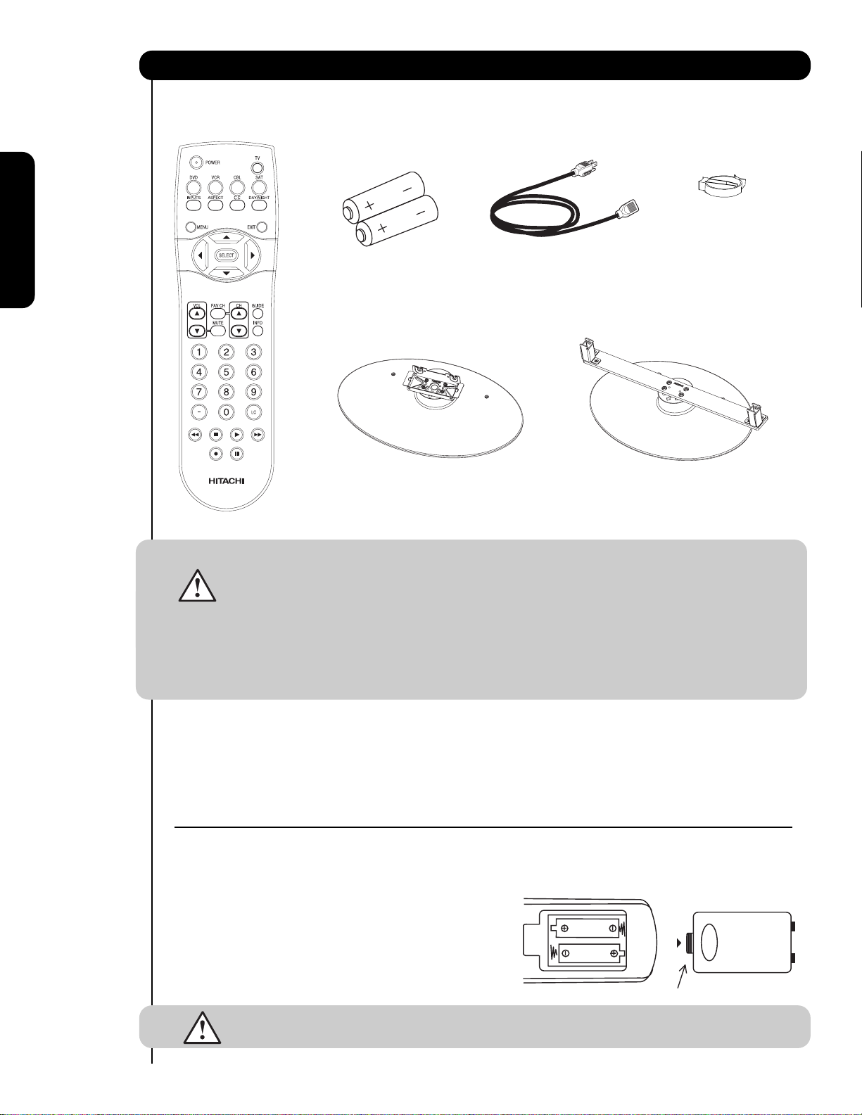
Accessories
Check to make sure you have the following accessories before disposing of the packing material.
쐃
Remote Control
First time use
쐇쐏
Two “AA” size,
1.5V batteries
Table Top Stand
쐋
(50" included)
Power Cord
쐄
Wire Clamp
(50" models only)
쐋
Table Top Stand
(42” included)
For U.S. models:
For optional accessories, please access our web site at:
www.hitachi.us/tv
Note : The accessories for models H4011, H4011A series are similar as the H401, H401A series.
CAUTION: 1. Ceiling mounting is not recommended. Mounting the panel on the ceiling does not
provide adequate ventilation for the electronics or proper support for the front glass
panel. This plasma television product is designed for a maximum tilting angle of 45
degrees from vertical.
2. This stand for use only with Hitachi P42H401, P42H401A, P50H401 and
P50H401A models. The use of other apparatus is capable of resulting in instability
causing possible injury.
3. The wall mount unit for the 50" and 42" models is WM07S and for the
55" models is WM07L. Please see page 7 for important information related
to the wall mount. Wall Mount unit is an optional accessory (Not Included).
쐃 Remote Control Unit CLU-4371UG2 (Part No HL02075 only H401 series)
Remote Control Unit CLU-4372UG2 (Part No HL02076 only H4011 series)
쐇 Two "AA" size, 1.5V batteries .
쐋 Table Top Stand (UX27661 42" model)
(UX27281 50" models).
쐏 Power Cord (P# EV01841).
REMOTE CONTROL BATTERY INSTALLATION AND REPLACEMENT
1.
Open the battery cover of the remote control by pushing down and sliding the back cover off.
2.
Insert two new “AA” size batteries for the remote contr
springs and lift them out.
3. Match the batteries to the (+) and (-) marks in the battery
compartment.
4.
Insert the bottom of the battery
compartment first, push towards the springs and insert the
top of the battery
battery into the battery compartment.
5. Replace the cover.
CAUTION: Do not insert batteries with ‘+’ and ‘-’ polarities reversed as this may cause the batteries
to swell or rupture resulting in leakage.
, the (+) side, into place. Do not for
, the (-) side, into th e battery
ol. When r
ce the
eplacing old batteries, push them towards the
Bottom View (Remote Control)
Lift up on tab to r
Note: Please visit our
website for optional
accessories.
쐄 Wire Clamp (50" models only)
emo ve back cover.
4
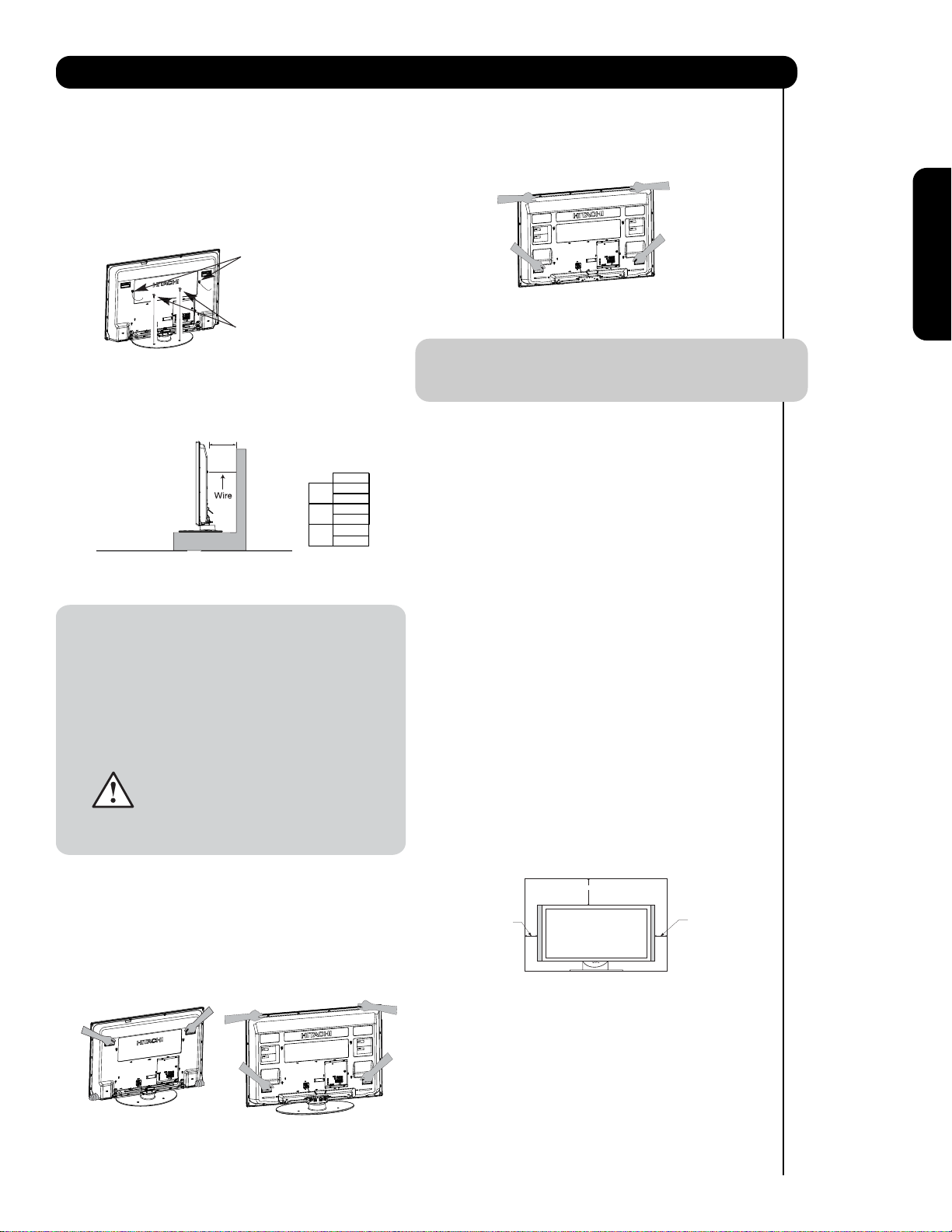
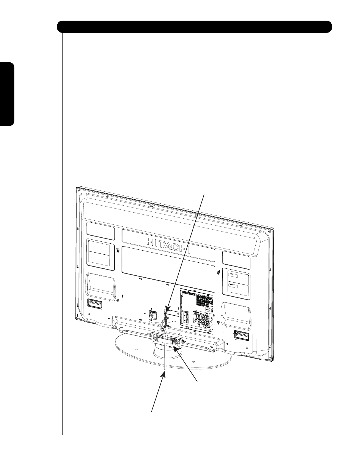
How To Set Up Your New Hitachi Plasma Television
To take measures to prevent the Plasma Television from tipping over and prevent possible injury
it is important to mount the unit in a stable and flat surface.
Securing to a table-top
1. Using wood screws (two) fasten the set to the
clamping screw holes on the rear of the Plasma
TV stand as shown below.
2. Using commercially available wood screws, secure
the set firmly in position.
Wire
55”
Wood screw
two places
Securing to a Wall
1. Keep the Plasma television 4 inches away from the
wall except when mounted using the wall mount
bracket.
2. Secure the television to the wall as shown.
A
A
42"
4 in.
10 cm
50"
4 in.
10 cm
55"
4 in.
10 cm
* Please adjust the wire length to avoid
touching the wall when turning the TV.
NOTES: 1. Do not block the ventilation holes of the
Plasma Television. Blocking the ventilation
holes might cause fire or defect.
2. In case of an abnormal symptom, unplug
the AC cord.
3. If you purchased the wall mount bracket
option, please ask for professional installer.
Do not install by yourself.
4. Install the unit at a proper area where it does
not expose anyone to any danger of hitting
themselves (for example their hands, head
or face, etc.) against the edge of the unit and
cause personal injury.
NOTE: The Table Top Stand for model P55H401 and
P55H4011 is not included (Optional).
ANTENNA
Unless your Plasma Television is connected to a cable
TV system or to a centralized antenna system, a good
outdoor color TV antenna is recommended for best
performance. However, if you are located in an
exceptionally good signal area that is free from
interference and multiple image ghosts, an indoor
antenna may be sufficient.
LOCATION
Select an area where sunlight or bright indoor
illumination will not fall directly on the picture screen.
Also, be sure that the location selected allows a free
flow of air to and from the perforated back cover of the
set. In order to prevent an internal temperature
increase, maintain a space of 10 cm (4 inches) from the
sides/back of the Television, and 30 cm (12 inches)
from the top of the television to the wall. To avoid
cabinet warping, cabinet color changes, and increased
chance of set failure, do not place the TV where
temperatures can become excessively hot, for
example, in direct sunlight or near a heating appliance,
etc.
First time use
Caution when moving the main unit
As this product is heavy, whenever it is moved, two
people are required to transport it safely. Whenever the
unit is moved it should be lifted forward using the top
and base on both sides of the Television for stability.
When moving the Television, lift the handles , then
support the top frame as shown below.
42” 50”
10 cm (4 inches)
30 cm (12 inches)
10 cm (4 inches)
5
How to set up your new HITACHI Plasma Television
AC CORD INSTALLATION INSTRUCTION
The AC cord provided with your new Plasma Television needs to be installed correctly
to avoid the AC cord from disconnecting when rotating the TV on its Table top stand.
Located on the back of the TV are 2 plastic clamps to hold the AC cord. Please follow the
instructions below.
쐃
Pass the AC cord through Clamp #1 and connect
it to the TV. Pull on the clamp to tighten the
AC cord to the TV.
쐇
First time use
The AC cord and the signal cables can all be
held together with Clamp #2.
쐋
Depend on the model size 42",50" or 55", the
clamp may be different shapes. Only for 50" models
the clamp #2 will be included on the accessories
bag.
Clamp #1 : Pass the AC cord through this clamp ;
쐃
then pull the clamp to tighten the AC
cord to the TV.
Clamp #2: Use this clamp to hold the AC cord and
쐇
the signal cables. For 50 " model please
assemble this Clamp on the middle hole
of the base metal.
AC CORD
6
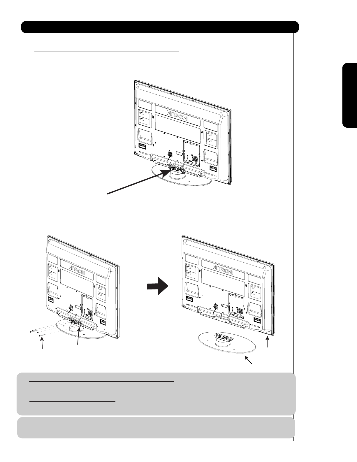
How to set up your new HITACHI Plasma Television
SETTING FOR WALL MOUNTING ON 50" & 55" MODELS
STEP (1) :
Please locate the STAND METAL on the back of the TV . This metal is use to hold the TV and the Base ; so it needs
to remove 4 screws from the STAND base in order to separate the TV from the Base.
STAND METAL
STEP (2):
Please remove the 4 screws of the STAND metal from the TV, now the TV STAND can be separated from the TV.
For dimensions of the WALL MOUNT assembly please refer to page 61 & 62.
First time use
4 SCREWS
STAND METAL
TV STAND BASE
For Model P50H401, P50H401A, P50H4011 and P50H4011A
CAUTION- This Plasma Display Panel for use only with Hitachi WM07S Wall Mount. Use with other
Wall Mount is capable of resulting in instability causing possible injury.
For Model P55H401 and P55H4011
CAUTION- This Plasma Display Panel for use only with Hitachi WM07L Wall Mount. Use with other
Wall Mount is capable of resulting in instability causing possible injury.
NOTE: Use the specified WALL MOUNT unit for the Plasma TV depending on the size of your TV.
Please access our web site at: www.hitachi.us/tv for recommended accessories for your tv.
7
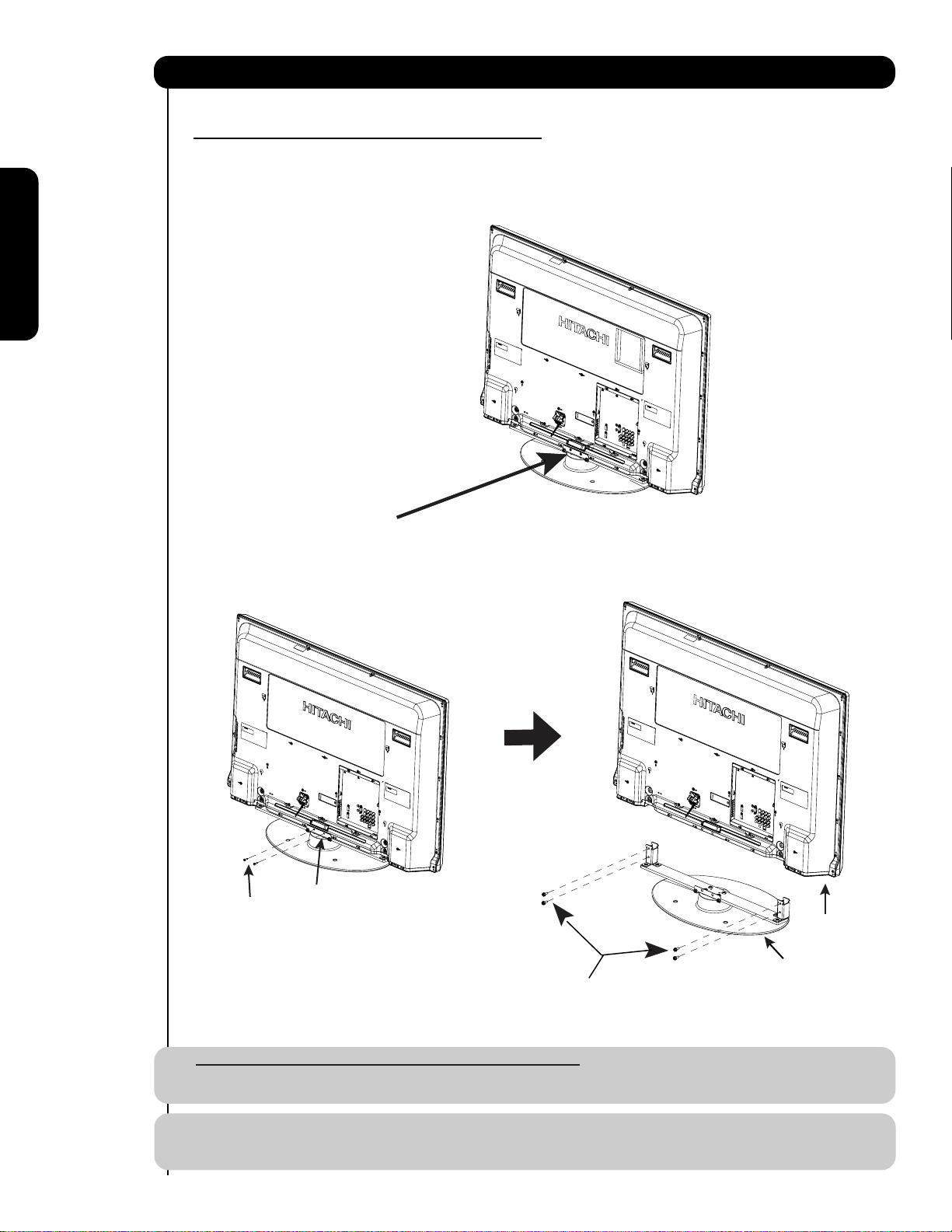
How to set up your new HITACHI Plasma Television
SETTING FOR WALL MOUNTING ON 42" MODELS
STEP (1) :
Please locate the STAND METAL on the back of the TV . This metal is use to hold the TV and the Base ; so it needs
to remove 6 screws from the STAND base in order to separate the TV from the Base.
First time use
STAND METAL
STEP (2):
Please remove the 2 screws of the STAND metal from the TV, then remove 4 screws that hold the TV STAND BASE;
now the TV STAND can be separated from the TV.For dimensions of the WALL MOUNT assembly please refer to page 60.
2 SCREWS
STAND METAL
Remove these 2 screws
first to separate the TV
rom the stand metal.
f
Then put these 2 screws
back to the TV.
Remove these 4 screws
to separate the TV from
TV STAND BASE
the stand base.
For Model P42H401, P42H401A, P42H4011 and P42H4011A
CAUTION- This Plasma Display Panel for use only with Hitachi WM07S Wall Mount. Use with other
Wall Mount is capable of resulting in instability causing possible injury.
NOTE: Use the specified WALL MOUNT base for the Plasma TV depending on the size of your TV.
Please access our web site at: www.hitachi.us/tv for recommended accessories for your tv.
8
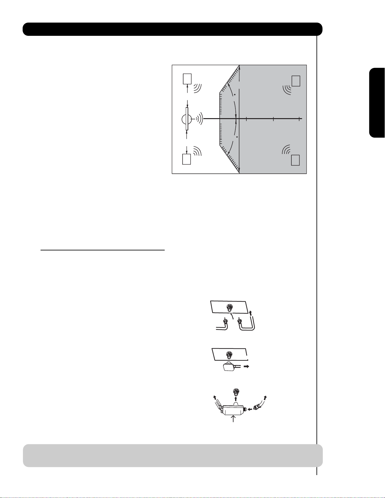
How to set up your new HITACHI Plasma Television
VIEWING
The best picture is seen by sitting directly in front of
the TV and about 10 to 18 feet from the screen.
During daylight hours, reflections from outside light
may appear on the screen. If so, drapes or screens
can be used to reduce the reflection or the TV can
be located in a different section of the room.
If the TV’s audio output will be connected to a Hi-Fi
system’s external speakers, the best audio
performance will be obtained by placing the
speakers equidistant from each side of the receiver
cabinet and as close as possible to the height of
the picture screen center. For best stereo
separation, place the external speakers at least
four feet from the side of the TV, place the surround
speakers to the side or behind the viewing area.
Differences in room sizes and acoustical
environments will require some experimentation
with speaker placement for best performance.
R
4" Minimum
4" Minimum
L
80
BEST
HORIZONTAL
5'
10'
VIEWING ANGLE
80
15' 20'
First time use
S
S
ANTENNA CONNECTIONS TO REAR JACK
PANEL
VHF (75-Ohm) antenna/CATV (Cable TV)
When using a 75-Ohm coaxial cable system, connect CATV coaxial cable to the AIR/CABLE (75-Ohm) terminal.
Or if you have an antenna, connect the coaxial cable to the same AIR/CABLE terminal.
AIR / CABLE
To CATV cable
VHF (300-Ohm) antenna/UHF antenna
When using a 300-Ohm twin lead from an outdoor
antenna, connect the VHF or UHF antenna leads to
screws of the VHF or UHF adapter. Plug the adapter
To outdoor antenna
or
into the antenna terminal on the TV.
AIR / CABLE
When both VHF and UHF antennas are
connected
Attach an optional antenna cable mixer to the TV
antenna terminal, and connect the cables to the
antenna mixer. Consult your dealer or service store for
the antenna mixer.
To UHF
antenna
AIR / CABLE
To outdoor VHF
or UHF antenna
To outdoor antenna
or CATV system
Antenna Mixer
NOTE: Connecting a 300-Ohm twin lead connector may cause interference. Using a 75-Ohm coaxial
cable is recommended.
9
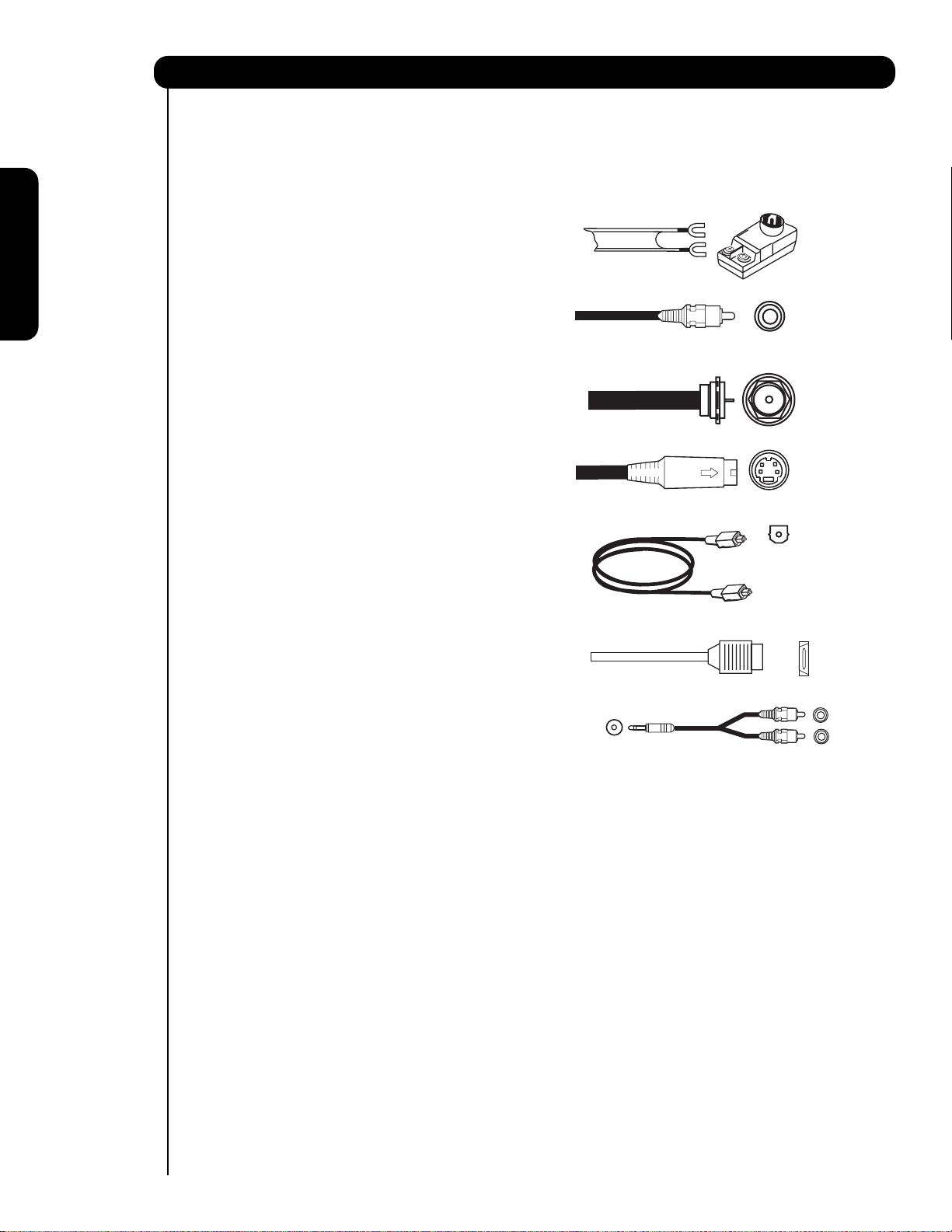
Hook-up Cables and Connectors
Most video/audio connections between components can be made with shielded video and audio cables that have
phono connectors. For best performance, video cables should use 75-Ohm coaxial shielded wire. Cables can be
purchased from most stores that sell audio/video products. Below are illustrations and names of common
connectors. Before purchasing any cables, be sure of the output and input connector types required by the
various components and the length of each cable.
300-Ohm Twin Lead
Cable
This outdoor antenna cable must be connected to an
antenna adapter (300-Ohm to 75-Ohm).
Phono or RCA
Cable
Used on all standard video and audio cables which
First time use
connect to inputs and outputs located on the
television’s rear jack panel and front control panel.
“F” Type 75-Ohm Coaxial Antenna
For connecting RF signals (antenna or cable TV) to the
antenna jack on the television.
S-Video (Super Video)
Cable
This connector is used on camcorders, VCRs and laserdisc players with an S-Video feature in place of the
standard video cable to produce a high quality picture.
Optical Cable
This cable is used to connect to an audio amplifier with
an Optical Audio In jack. Use this cable for the best
sound quality.
HDMI Cable
This cable is used to connect your external devices
such as Set-Top-Boxes or DVD players equipped with
an HDMI output connection to the TV’s HDMI input.
Stereo Cable (3.8mm plug to 3.5mm plug)
Used on all standard video and audio cable which
connect to inputs and outputs located on the rear jack
panel and front control panel.
AUDIO OUT
3.8mm
STEREO
MINI-PLUG
2
RCA TYPE
PLUGS
10
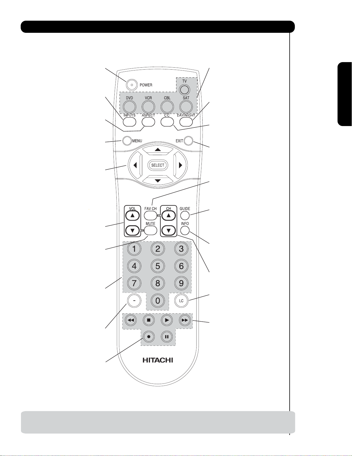
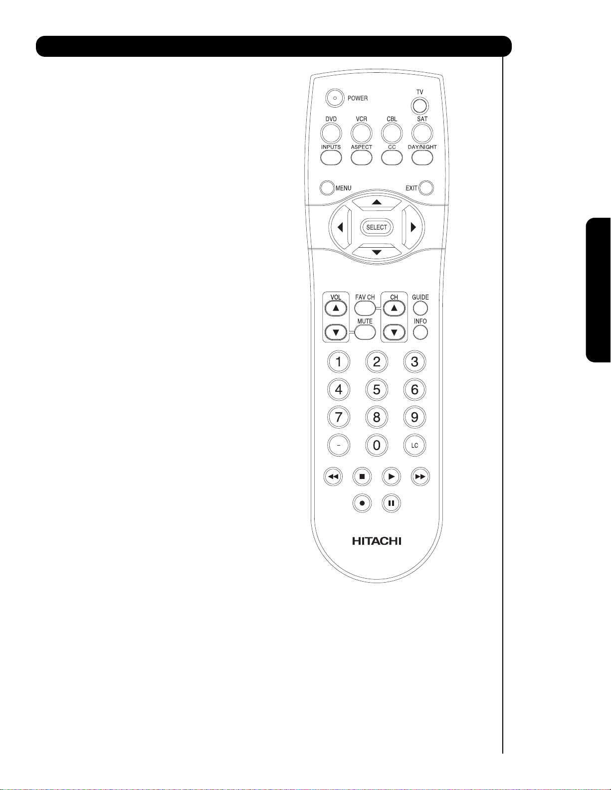
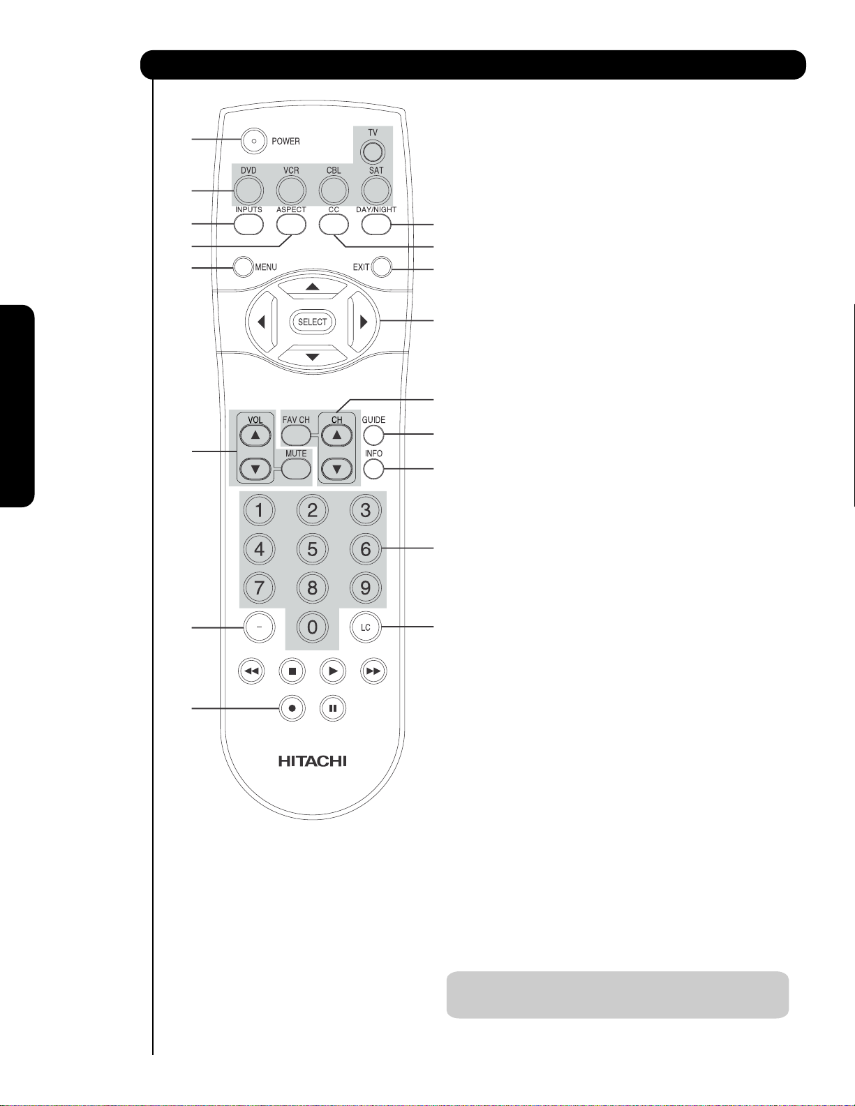
Quick Reference Remote Control Buttons and Functions
In addition to controlling all of the functions on your HITACHI Plasma TV, the new remote control is
designed to operate different types of devices, such as, DVD Players, CBL (Cable Boxes), set-top-boxes, satellite
receivers, and VCRs. The remote control must be programmed to control the chosen device. Please see pages 2331 for a complete description of all features and programming of the Remote Control.
(TV, CBL, VCR, DVD, SAT)
POWER BUTTON
Turns the selected device on
and off.
INPUTS BUTTON (TV)
Accesses the INPUTS menu
system.
ASPECT BUTTON (TV)
Changes the aspect ratio while
watching TV.
MENU BUTTON
(CBL, DVD, SAT, TV)
Accesses the OSD menu
system.
CURSOR/SELECT BUTTONS
(TV, DVD, CBL, SAT)
The CURSOR buttons are used
to navigate the cursor through
the OSD and INPUTS menu
systems, and the SELECT
button is used to
Select/Activate the highlighted
menu item.
VOLUME BUTTONS (TV)
Adjusts the audio level of your
TV.
MUTE BUTTON (TV)
Reduces the audio level to 50%
if pressed once, and to
complete mute if pressed twice.
Press it a third time to restore
audio level.
NUMERIC BUTTONS
(TV, DVD, CBL, SAT, VCR)
Used to manually enter the TV
channel, and used for numeric
entry when navigating through
the OSD menu system.
(-) BUTTON (TV, SAT)
The (-) button is used when the
remote is in Set-Top-Box (STB)
mode or when the TV uses a
digital input.
SOURCE ACCESS BUTTONS
(TV, DVD, VCR, CBL, SAT)
Changes the mode of the
Universal Remote Control to
control the device selected.
DAY/NIGHT BUTTON (TV)
Select picture mode settings
between DAY and NIGHT mode.
CC BUTTON (TV)
Press to show and change the
Closed Caption mode.
EXIT BUTTON
(TV, CBL, SAT)
Exits out of the OSD or INPUTS
menu systems if their menu is
displayed.
FAVORITE CHANNEL
(FAV CH) button (TV)
Press to enter/access Favorite
Channel (FAV) mode.
GUIDE BUTTON
(SAT/STB, CBL)
Accesses the program guide of
other devices.
INFO BUTTON
(TV, CBL, SAT)
Displays various information on
the screen.
CHANNEL BUTTONS
(TV, CBL, SAT, VCR)
Changes the channel.
LAST CHANNEL (LC) BUTTON
(TV, CBL, SAT)
Switches between the current
and last channel viewed.
DVD/VCR CONTROL
BUTTONS (DVD, VCR)
Controls the precode functions
of your VCR and DVD.
First time use
RECORD BUTTON (VCR)
Press twice (2 times) to record
programs.
LEGEND
TV — Television VCR — Video Cassette Recorder/Player
SAT — Satellite Receiver
CBL — Cable Box DVD — Digital Video Disc Player
NOTES: 1. The TV’s remote control sensor is located on the right bottom portion of the TV screen. To
control TV functions, please point the remote control directly at the remote control sensor for
best results.
11
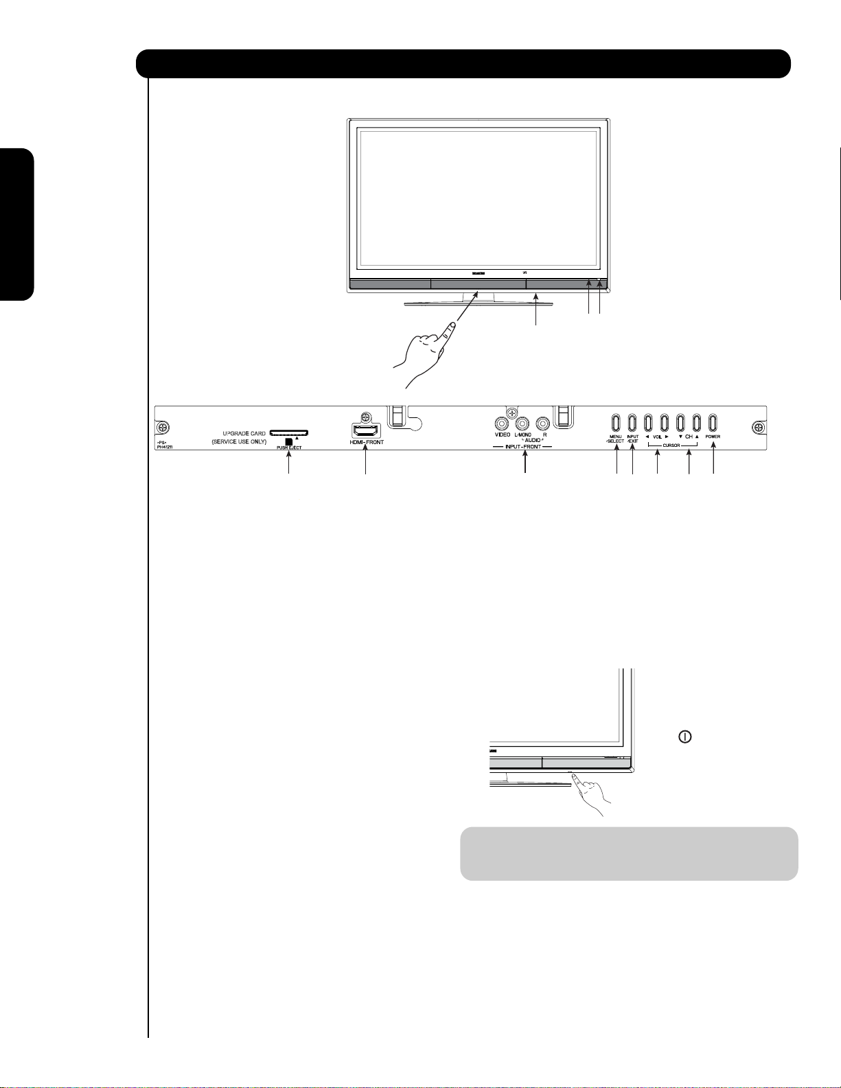
Front Panel Controls
FRONT VIEW
First time use
햺
햻
PUSH TO OPEN CONTROL DOOR
UPGRADE CARD
(SERVICE USE ONLY)
PUSH EJECT
햸
FRONT PANEL CONTROLS
햹
햲 FRONT POWER button
Press this button to turn the Plasma Television
ON/OFF. It can also be turned ON/OFF by remote
control. The “MAIN POWER” button must be at
stand-by mode.
햳 MENU/SELECT button
This button allows you to enter the MENU, making
it possible to set TV features to your preference
without using the remote. This button also serves
as the SELECT button when in MENU mode.
햴
HDMI-FRONT
Use the front HDMI input for extrenal devices such
as Set-Top-Boxes or DVD players equipped with an
HDMI output connection (see page 15 for reference).
햵 INPUT/EXIT button
Press this button to access the INPUT menu.
Press again to exit the MENU mode.
햶 CHANNEL selector
Press these buttons until the desired channel
appears in the top right corner of the TV screen.
These buttons also serve as the cursor down ()
and up () buttons when in MENU mode.
햷 VOLUME level
Press these buttons to adjust the sound level. The
volume level will be displayed on the TV screen.
These buttons also serve as the cursor left () and
right () buttons when in MENU mode.
12
햴
햳
햷
햽
햸 POWER button
Television MAIN POWER button
This power button is for the complete system, and
must be turned ON/OFF manually. It is
recommended to leave the “MAIN POWER” to ON
condition (lights red) for stand-by mode.
햵
햶
햲
The Main Power
button is located
on the broadside
bottom, under the
mark " ".
NOTE: When the “MAIN POWER” button is set to
OFF or the TV is unplugged, the clock will
stop and may eventually reset itself.
햹
Upgrade Card
This card slot is for future software upgrades.
Hitachi will notify you if a software upgrade is
required for your TV. In order to receive written
notification, please complete and return your
warranty card.
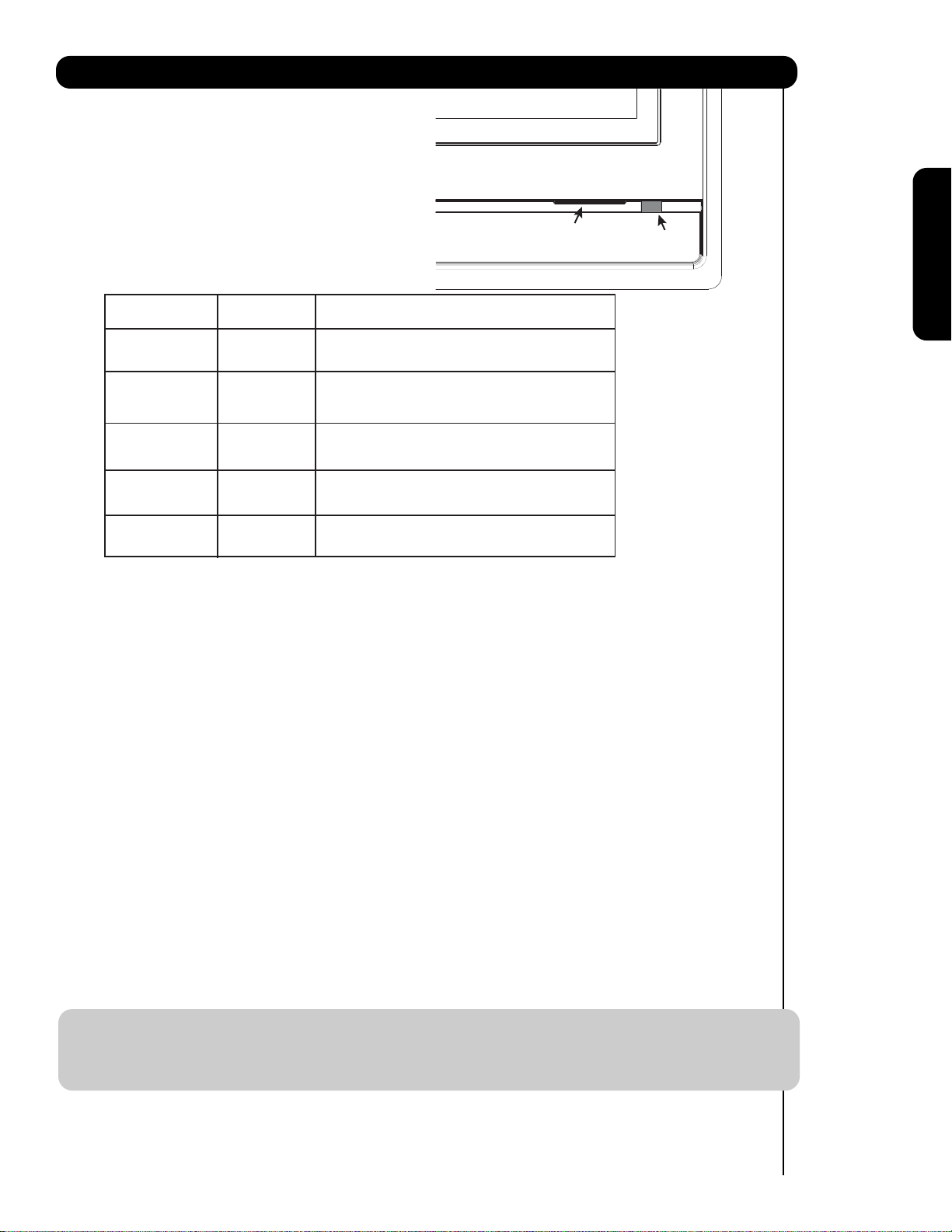
Front Panel Controls
햺
POWER light indicator
To turn the TV ON, press the main power
switch located on the lower right side of the
TV. A red stand-by indicator lamp located on
the lower right corner of the front bezel will
illuminate. The Plasma TV is now ready for
remote ON/OFF operation.
Indicating Lamp Power Status Operating
햺
Indicating Lamp
햻
R/C sensor
First time use
Off
Lights
Red
Lights
Blue
Lights
Orange
Blinking
Blue
햻
REMOTE CONTROL sensor
Point your remote at this area when selecting
channels, adjusting volume, etc.
INPUT-FRONT JACKS
햽
INPUT-FRONT provide composite Video jacks for
connecting equipment with this capability,
such as a DVD player or Camcorders.
OFF. When the main power switch is set to Off.
OFF.
(Stand-by)
On
Off
(Power Saving)
When the main power switch on the TV is ON.
TV MAIN POWER is ON ; picture is shown.
TV MAIN POWER is ON with no signal input
except antenna (no sync. signal).
On When TV receives the IR signal from R/C.
NOTES: 1. Your HITACHI Plasma TV will appear to be turned OFF (lights orange) if there is no video input
when INPUT : 1, 2, 3, Front or HDMI : 1, 2, Front is selected. Check the Power Light to
make sure the TV is turned off or in Stand-by mode (lights red) when not in use.
2. Remote Control can not turn ON/OFF the “MAIN POWER” of the TV.
13
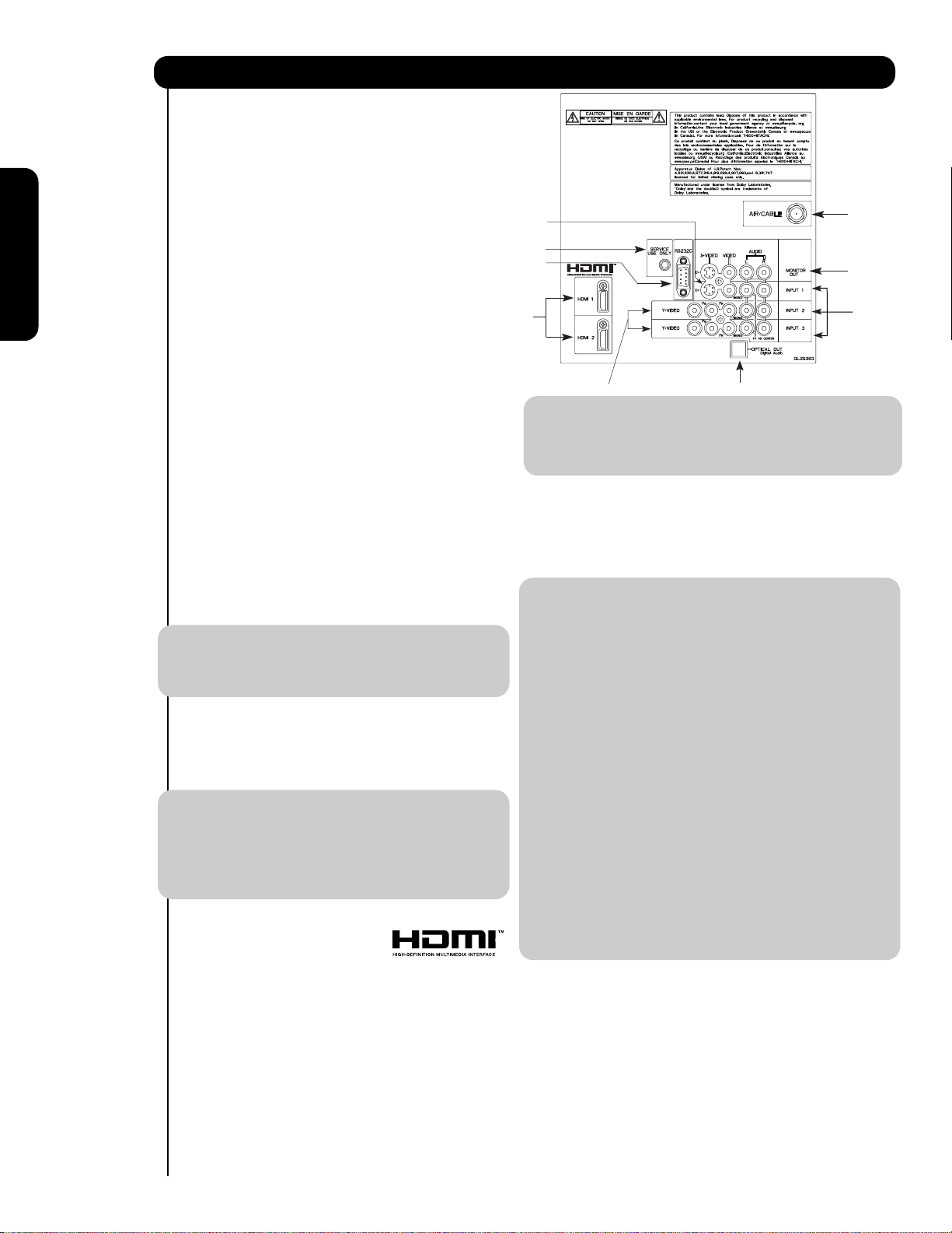
Rear Panel Connections
햲 Antenna Input
To switch between Cable and Air input, go to the
Channel Manager option to change the signal
source CABLE or AIR.
햳 Audio/Video Inputs 1, 2 and 3
By using the INPUTS button, the CURSOR PAD (
and ), and the SELECT button or CURSOR PAD
of the remote control, you can select each video
source. Use the audio and video inputs to connect
햶
햺
햹
햲
햴
external devices, such as VCRs, camcorders,
First time use
laserdisc players, DVD players etc. (if you have
햷
햳
mono sound, insert the audio cable into the left
audio jack).
햴 MONITOR OUT & AUDIO OUT
These jacks provide fixed audio and video
signals (CABLE/AIR or INPUTS ) which are
used for recording. Use the S-VIDEO output
for high quality video output. Component signal
햸
NOTE: 1. The HDMI input is not intended for use
with personal computers.
2. Only DTV formats such as 1080p, 1080i, 720p,
480i and 480p are available for HDMI input.
햵
to Input 2 and 3, and HDMI inputs will not
have monitor output.
햵 Optical Out (Digital Audio)
This jack provides Digital Audio Output for your
audio device that is Dolby
® Digital and PCM
compatible, such as an audio amplifier.
햸 Component: Y-P
INPUTS 2 and 3 provide Y-P
connecting equipment with this capability, such as
a DVD player or Set Top Box. You may use
composite video signal for both inputs.
NOTE: 1. Do not connect composite VIDEO and
BPR Inputs
BPR jacks for
S-VIDEO to INPUT 1 at the same time.
NOTE: *Manufactured under license from Dolby
Laboratories. “Dolby” and the double-D
symbol are trademarks of Dolby
Laboratories.
S-VIDEO has priority over VIDEO input.
2. Your component outputs may be labeled
Y, B-Y, and R-Y. In this case, connect the
components B-Y output to the TV’s P
B
input and the components R-Y output to
햶 S-VIDEO Input 1
Input 1 provide S-VIDEO (Super Video)
jacks for connecting equipment with S-VIDEO
output capability.
NOTE: 1. You may use VIDEO or S-VIDEO inputs to
connect to INPUT 1 , but only one of
these inputs may be used at a time.
2. S-VIDEO output may be used for
recording, only when the input is of
S-VIDEO type.
the TV’s P
3. Your component outputs may be labeled
Y-C
C
B output to the TV’s PB input and the
component C
4. It may be necessary to adjust TINT to
obtain optimum picture quality when using
the Y-P
5. To ensure no copyright infringement, the
MONITOR OUT output will be abnormal,
when using the Y-PBPR jacks and HDMI
R input.
BCR. In this case, connect the component
R output to the TV’s PR input.
BPR inputs (see page 34).
Input.
햷 HDMI 1, 2 (High Definition Multimedia
Interface)
ABOUT HDMI – HDMI is the
6. INPUT 2 , and 3 (Y/VIDEO) can be used for
composite video and component video
input.
next-generation all digital interface for consumer
electronics. HDMI enables the secure distribution
of uncompressed high-definition video and multichannel audio in a single cable. Because digital
햹 For Special AV control use only.
햺 For Factory use only.
television (DTV) signals remain in digital format,
HDMI assures that pristine high-definition images
retain the highest video quality from the source all
the way to your television screen.
Use the HDMI input for your external devices such
as Set-Top-Boxes or DVD players equipped with an
HDMI output connection.
HDMI, the HDMI logo and High-Definition
Multimedia Interface are trademarks or registered
14
trademarks of HDMI Licensing LLC.
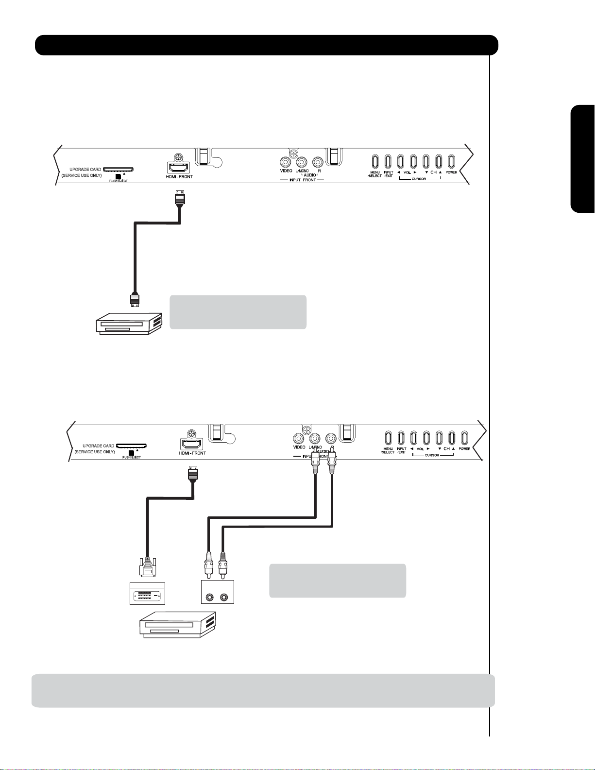
Connecting External Video Sources
The FRONT panel jacks are provided as a convenience to allow you to easily connect HDMI or DVI signals
from a DVD, Set Top Box , Video Game as shown in the following examples (When connecting DVI signal it will
need to connect the audio output into the Front Audio Input jacks) :
A) Connecting HDMI signal.
FRONT INPUT PANEL
UPGRADE CARD
(SERVICE USE ONLY)
PUSH EJECT
HDMI DIGITAL
OUTPUT CAPABILITY
DVD , Set Top Box,
Video Game Console.
B) Connecting DVI signal.
FRONT INPUT PANEL
First time use
Note : Special device cables will be
according to the own device
specifications.
UPGRADE CARD
(SERVICE USE ONLY)
PUSH EJECT
DVI to HDMI
Cab le
Note : Special device cables will be
DIGIT AL O UT P UT
OUTPUT
L R
according to the own device
specifications.
Back of
HDTV Set-Top-Box or
DVD Player
DVI DIGITAL
OUTPUT CAPABILITY
DVD , Set Top Box,
Video Game Console.
NOTE: 1. Completely insert connection cord plugs when connecting to front panel jacks. If you do not, the played back
picture may be abnormal.
15
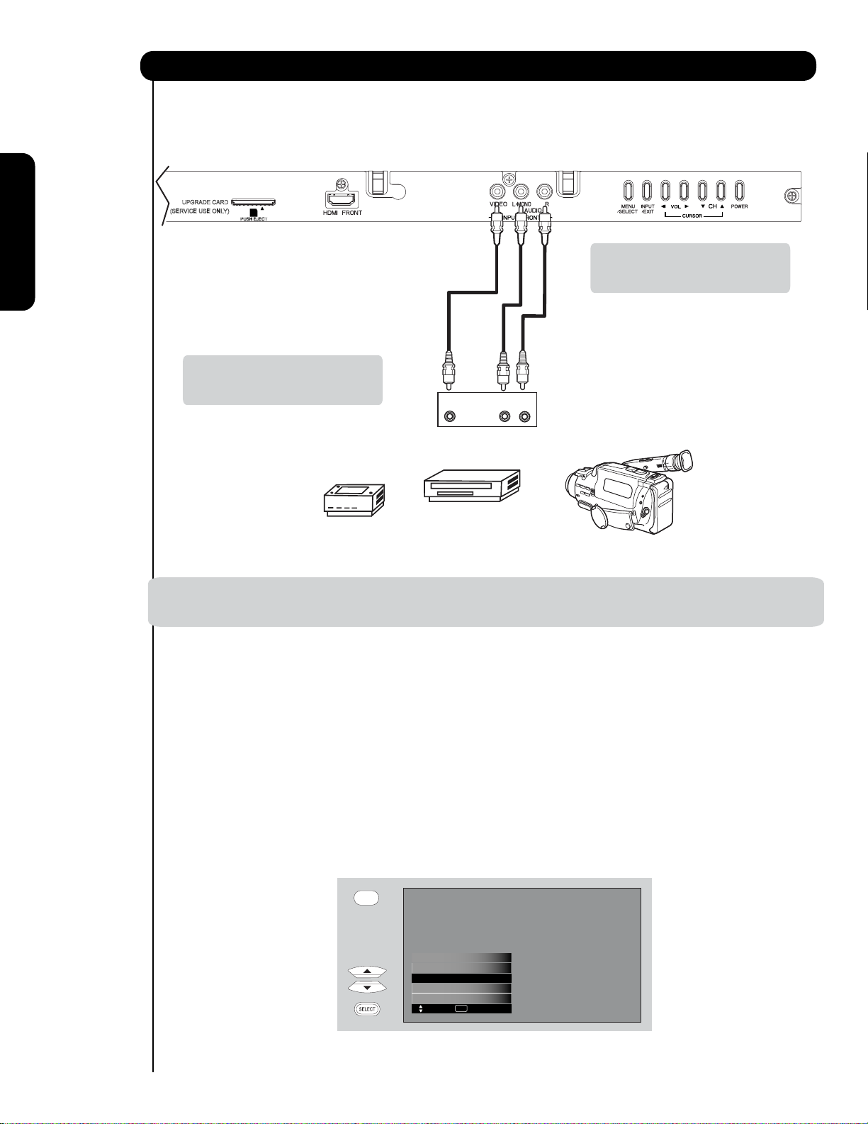
Connecting External Video Sources
The FRONT panel jacks are provided as a convenience to allow you to easily connect a camcorder , DVD, Video
Game and a VCR as shown in the following examples:
FRONT INPUT PANEL
UPGRADE CARD
(SERVICE USE ONLY)
PUSH EJECT
First time use
Note : Special device cables will be
according to the own device
specifications.
-
Note : For Monoaural devices, please
connect Audio signal cable into
L/Mono input jack .
OUTPUT
Video
L R
COMPOSITE VIDEO
Video Game
OUTPUT CAPABILITY
DVD , Video Game
Console.
Video Camera
NOTE:1. Completely insert connection cord plugs when connecting to front panel jacks. If you do not, the
played back picture may be abnormal.
The exact arrangement you use to connect the VCR, camcorder, laserdisc player, DVD player, or HDTV Set
Top Box to your Plasma TV is dependent on the model and features of each component. Check the
owner’s manual of each component for the location of video and audio inputs and outputs.
The following connection diagrams are offered as suggestions. However, you may need to modify them to
accommodate your particular assortment of components and features. For best performance, video and
audio cables should be made from coaxial shielded wire.
Before Operating External Video Source
Connect an external source to one of the INPUT terminals, then press the INPUTS button to show the
INPUTS menu. Use the CURSOR PAD ( and ) to select the Input of your choice. Then press
the SELECT button or the CURSOR PAD to confirm your choice (see page 26).
INPUTS
16
HDMI 2
HDMI-Front
Cable
Air /
Input 1
Input 2
Move SEL Sel.
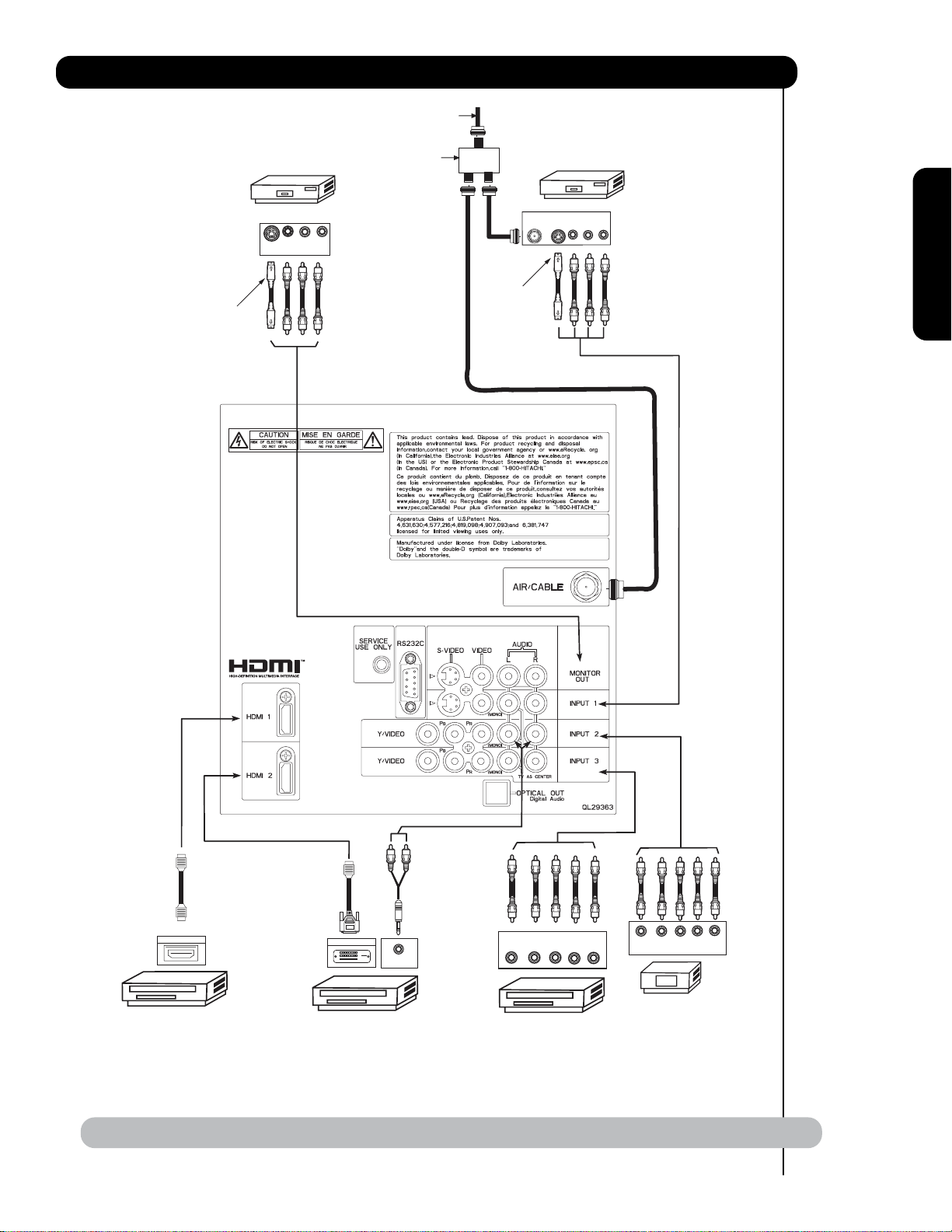
Rear Panel Connections
VCR #2
V L R
S-VIDEO
INPUT
Optional
Outside Antenna
or
Cable TV coaxial cable
2-Way signal splitter
ANT
IN
Optional
S-VIDEO
VCR #1
OUTPUT
VLR
First time use
HDMI
to
HDMI
HDMI OUTPUT
HDMI DIGITAL
OUTPUT CAPABILITY
DVI
to
HDMI
DIGITAL OUTPUT
DIGITAL
OUTPUT CAPABILITY
AUDIO OUT
NOTE: Cables are optional, except when specified.
YP
B/CBPR/CR
DVD Player
OUTPUT
L R
P
Y P
B
R
OUTPUT
HDTV Set-Top Box
L R
17

Tips on Rear Panel Connections
• S-VIDEO, Y-PBPR, or HDMI connections are provided for high performance laserdisc players, VCRs etc. that
have this feature. Use these connections in place of the standard video connection if your device has this
feature.
• If your device has only one audio output (mono sound), connect it to the left audio jack on (L/(MONO)) the
Rear Panel.
• Refer to the operating guide of your other electronic equipment for additional information on connecting
your hook-up cables.
• A single VCR can be used for VCR #1 and VCR #2, but note that a VCR cannot record its own video or line
output (INPUT: 1 in the example on page 17). Refer to your VCR operating guide for more information on
First time use
line input-output connections.
• Connect only 1 component (VCR, DVD player, camcorder, etc.) to each input jack.
• COMPONENT: Y-P
DVD players and set-top-boxes. Use these connections in place of the standard video connection if your
device has this feature.
• Your component outputs may be labeled Y, B-Y, and R-Y. In this case, connect the components B-Y
output to the TV’s PBinput and the components R-Y output to the TV’s PRinput.
• Your component outputs may be labeled Y-C
TV’s P
• It may be necessary to adjust TINT to obtain optimum picture quality when using the Y-PBPRinputs. (See
page 34).
• To ensure no copyright infringement, the MONITOR OUT output will be abnormal, when using the Y-P
HDMI input jacks.
• Input HDMI 1, HDMI 2 or HDMI FRONT can accept HDMI signal.
• S-VIDEO monitor output may be used for recording only when the input is of S-VIDEO type.
• When using a HDMI input from a Set-Top-Box, it is recommended to use a 1080p, 1080i or 720p input signal.
• When HDMI input a 1080p signal, it is recommended that the length of the cable should be less than 5 meters.
INSTALLATION RECOMMENDATION:
1. Video signals fed through a VCR may be affected by copyright protection systems and the picture
will be distorted on the television.
2. Connecting the television directly to the Audio /Video output of a Set-Top-Box will assure a more
normal picture.
input and the components CRoutput to the TV’s PRinput.
B
(Input 2 & 3) connections are provided for high performance components, such as
BPR
. In this case, connect the components CBoutput to the
BCR
BPR and
18
Connecting External Video Sources
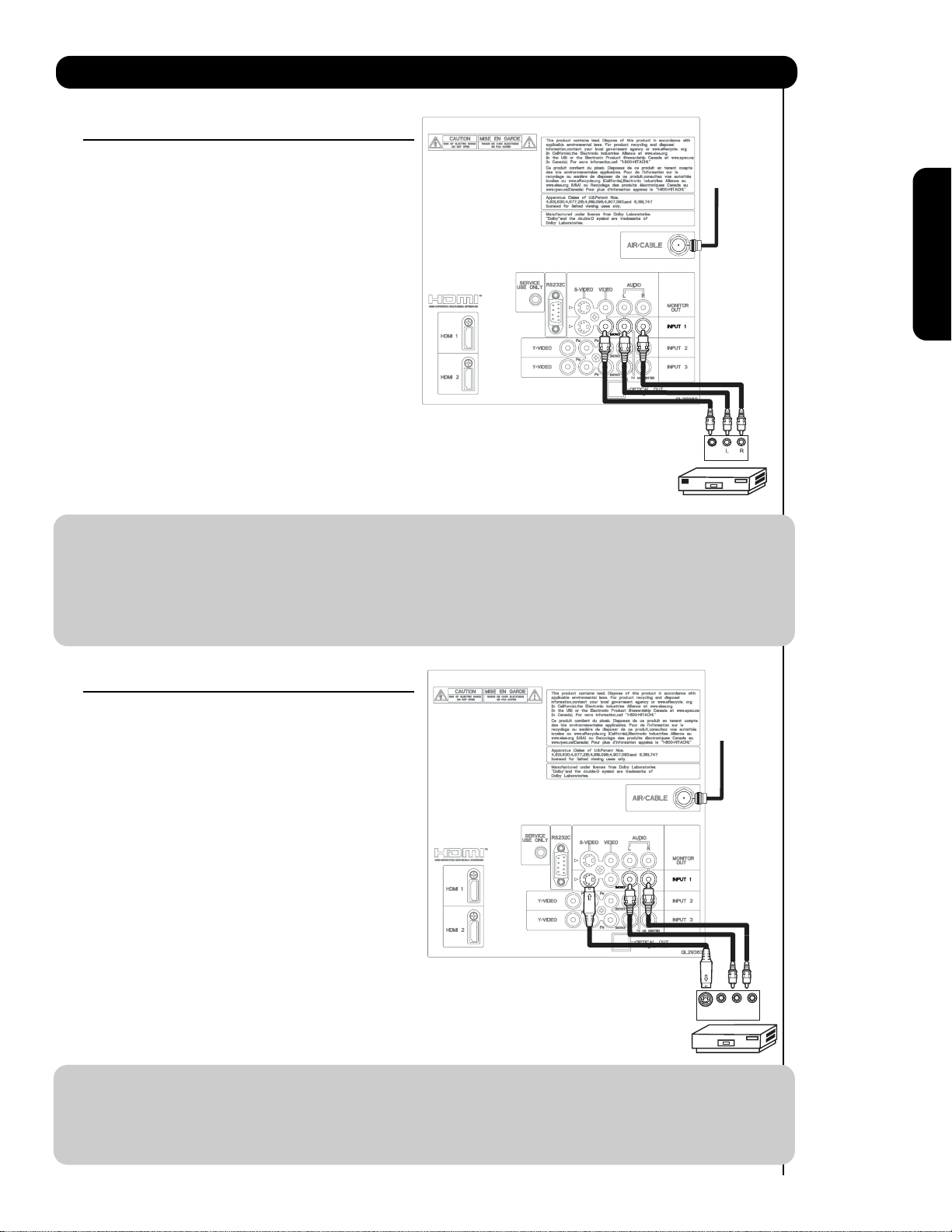
CONNECTING A VIDEO AND STEREO AUDIO
SOURCE TO INPUT1 ~ INPUT-FRONT
1. Connect the cable from the VIDEO OUT of the
VCR or the laserdisc player to the INPUT
Cable or
Air signal
(VIDEO) jack, as shown on the Rear Panel to the
right.
2. Connect the cable from the AUDIO OUT R of the
VCR or the laserdisc player to the INPUT
(AUDIO/R) jack.
3. Connect the cable from the AUDIO OUT L of the
VCR or the laserdisc player to the INPUT
(AUDIO/L) jack.
4. Press the INPUTS button, then select INPUT 1
2,3 or Front from the INPUTS menu to view the
program from the VCR or laserdisc player.
Back of
5. Select CABLE or AIR from the INPUTS menu to
VCR
Video
OUTPUT
return to the last channel tuned.
VCR
NOTE: 1. Completely insert the connection cord plugs when connecting to rear panel jacks. The picture and
sound that is played back will be abnormal if the connection is loose.
2. A single VCR can be used for VCR #1 and VCR #2 (see page 17) but note that a VCR cannot record
its own video or line output. Refer to your VCR operating guide for more information on line inputoutput connections.
3. When INPUT 2 or 3 are used, it is necessary to connect the video output of the device to the
Y/VIDEO input jack of the TV .
First time use
CONNECTING AN S-VIDEO AND STEREO AUDIO
SOURCE TO INPUT 1
1. Connect the cable from the S-VIDEO OUT of
the S-VHS VCR or the laserdisc player to the
Cable or
Air signal
INPUT (S-VIDEO) jack, as shown on the Rear
Panel to the right.
2. Connect the cable from the AUDIO OUT R of
the VCR or the laserdisc player to the INPUT
(AUDIO/R) jack.
3. Connect the cable from the AUDIO OUT L of
the VCR or the laserdisc player to the INPUT
(AUDIO/L) jack.
4. Press the INPUTS button, then select INPUT 1
from the INPUTS menu to view the program
from the VCR or laserdisc player.
5. Select CABLE or AIR from the INPUTS menu to
return to the last channel tuned.
Back of VCR or
Laserdisc Player
Video L R
S-VIDEO
OUTPUT
VCR or Laserdisc Player
NOTE: 1. Completely insert the connection cord plugs when connecting to rear panel jacks. The picture and
sound that is played back will be abnormal if the connection is loose.
2. A single VCR can be used for VCR #1 and VCR #2 (see page 17), but note that a VCR cannot record
its own video or line output. Refer to your VCR operating guide for more information on line inputoutput connections.
19
Connecting External Video Sources
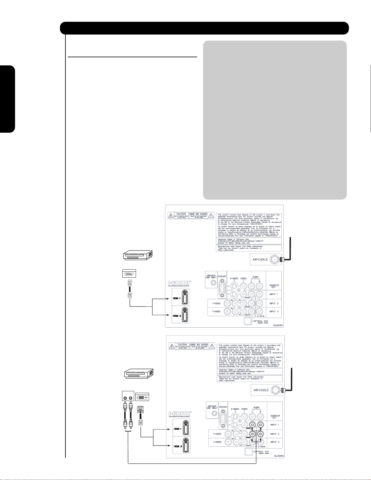
CONNECTING A COMPONENT SOURCE WITH HDMI OR
DVI CAPABILITY TO HDMI 1, HDMI 2 OR HDMI FRONT
NOTE: 1. Completely insert the connection cord
plugs when connecting to rear panel jacks.
The picture and sound that is played back
1. Connect the HDMI or DVI to HDMI connection
cable from the output of the HDTV set top box
or DVD player to the HDMI input as shown
on the Rear panel below.
2. With DVI output, connect the cable from the
AUDIO OUT R of the HDTV set top box or DVD
player to the INPUT (AUDIO/R) jack as shown on
First time use
the Rear Panel below.
3. With DVI output, connect the cable from the
AUDIO OUT L of the HDTV set top box or DVD
player to the INPUT (AUDIO/L) jack as shown
on the Rear Panel below.
4. Press the INPUTS button, then select HDMI 1, 2
or FRONT to view the program from the HDTV
SET TOP BOX or DVD player.
will be abnormal if the connection is loose.
2. The HDMI input on HDMI 1 , 2 and FRONT
contains the copy protection system called
High-bandwidth Digital Content Protection
(HDCP). HDCP is a cryptographic system
that encrypts video signals when using
HDMI connections to prevent illegal
copying of video contents.
3. HDMI is not a “NETWORK” technology. It
establishes a one-way point-to-point
connection for delivery of uncompressed
video to a display.
4.
The connected digital output device
controls the HDMI interface so proper set-up
of device user settings determines final
video appearance.
5. When using a DVI to HDMI cable, connect the
Audio Out L and R cables at the same INPUT
5. Select CABLE or AIR from the INPUTS menu to
return to the last channel viewed.
(1 , 2 or Front) as your HDMI INPUT(1 , 2 or Front).
(For FRONT INPUT see page 15 for reference).
HDMI input
HDTV Set-Top-Box or
DVD Player
DIGITAL OUTPUT
HDMI
Cable
DVI to HDMI Input
HDTV Set-Top-Box or
DVD Player
Back of HDTV
Set-Top-Box
or DVD Player
OUTPUT
LR
Back of
HDTV Set-Top-Box or
DVD Player
DIGITAL OUTPUT
CABLE
or
Air signal
or
CABLE
or
Air signal
20
DVI to HDMI
Cable
or
or
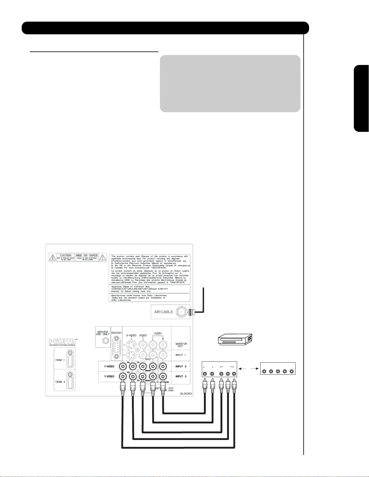
Connecting External Audio/Video Devices
CONNECTING A COMPONENT AND STEREO
AUDIO SOURCE TO INPUT 2 or 3 :Y-PBPR.
1. Connect the cable from the Y OUT of the
Laserdisc/DVD player or HDTV set top box to
the INPUT (Y) jack, as shown on the Rear
panel below.
2. Connect the cable from the PB/CBOUT or BY OUT of the Laserdisc/DVD player or HDTV
set top box to the INPUT (PB)jack.
3. Connect the cable from the PR/CROUT or RY OUT of the Laserdisc/DVD player or HDTV
set top box to the INPUT (PR) jack.
4. Connect the cable from the AUDIO OUT R of
the Laserdisc/DVD player or HDTV set top box
to the INPUT (AUDIO/R) jack.
5. Connect the cable from the AUDIO OUT L of
the Laserdisc/DVD player or HDTV set top box
to the INPUT (AUDIO/L) jack.
6. Press the INPUTS button, then select INPUT 2 or 3
from the INPUTS menu to view the program
from the Laserdisc/DVD player or HDTV set
top box.
7. Select CABLE or AIR to return to the last
channel tuned.
NOTE: 1. Completely insert the connection cord
plugs when connecting to rear panel jacks.
The picture and sound that is played back
will be abnormal if the connection is loose.
2. See page 18 for tips on REAR PANEL
CONNECTIONS.
First time use
CABLE
or
Air signal
AUDIO
R
Back of
DVD Player
OUTPUT
L
DVD Player
VIDEO
PR/CR PB/CB Y
OR
OUTPUT
L R Y P
HDTV Set-Top Box
B P
R
21
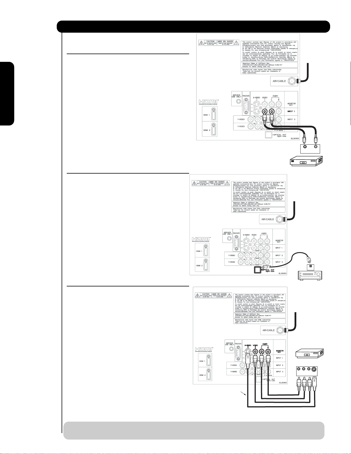
Connecting External Audio/Video Devices
CONNECTING A VIDEO AND MONAURAL AUDIO
SOURCE TO INPUT 1 ~ FRONT INPUT
CABLE
or
Air signal
1. Connect the cable from the VIDEO OUT of the
VCR or the laserdisc player to the INPUT
(VIDEO) jack, as shown on the Rear Panel on the
right.
2. Connect the cable from the AUDIO OUT of the
VCR or the laserdisc player to the INPUT
(MONO)/L(AUDIO) jack.
First time use
3. Press the INPUTS button, then select INPUT 1
2,3 or Front from the INPUTS menu to view the
program from the VCR or the laserdisc player.
4. Select CABLE or AIR from the INPUTS menu to
return to the previous channel.
Back of
VCR
VIDEO OUT AUDIO OUT
OUTPUT
(For INPUT FRONT please see page 16 for reference).
CONNECTING AN EXTERNAL AUDIO AMPLIFIER
VCR
To monitor the audio level of the Plasma TV to an
external audio amplifier, connect the system as
shown on the right. The “OPTICAL OUT” from the
CABLE
or
Air signal
Rear Panel is a fixed output. The Volume of the
amplifier is controlled by the amplifier, not by the
Plasma Television. The OPTICAL OUT terminal
outputs all audio sources with Optical IN capability.
1. Connect an optical cable from the Optical out to
the Optical input of a separate Stereo System
Amplifier as shown on the Rear Panel on the
right.
CONNECTING MONITOR OUT
The MONITOR OUT terminal outputs video and
audio of CABLE/AIR and INPUTS 1, 2, 3 and Front.
It does not output component and HDMI video.
1. Connecting S-Video:
Connect the cable from the S-VIDEO OUT of
the Rear Panel to the INPUT (S-VIDEO) jack, of
the VCR or Laserdisk player.
Connecting Video:
Connect the cable from the VIDEO INPUT of
the VCR or the laserdisc player to the VIDEO
out jack on the TV Rear Panel.
2. Connect the cable from the AUDIO IN R of the
VCR or the laserdisc player to the OUTPUT
(AUDIO/R) jack on the TV Rear Panel.
Optional
Stereo System Amplifier
OPTICAL
Stereo System Amplifier
or DVD Player
CABLE
or
Air signal
VCR or other external
components
R L V
INPUT
IN
S-VIDEO
3. Connect the cable from the AUDIO IN L of the
VCR or the laserdisc player to the OUTPUT
(AUDIO/L) jack on the TV Rear Panel.
NOTE: When making video connections, connect S-Video only or Video only. If both are connected, S-Video
22
takes priority.
The Remote Control
In addition to controlling all the functions on your
HITACHI Plasma Television , the new remote control
is designed to operate different types of VCRs,
CATV (Cable TV) converters, set-top-boxes, satellite
receivers (SAT) and DVD players with one touch. Basic
operation keys are grouped together in one area.
To operate your TV, press the TV button. The remote
will now control your television.
To operate your VCR, press the VCR button. The
remote will now control your VCR (see page 31 for
instructions on how to program the remote to control
your VCR).
To operate your cable box, press the CABLE (CBL)
button. The remote will now control your cable box
(see page 28 for instructions on how to program the
remote to control your cable box).
To operate your set-top-box or satellite receiver,
press the SAT button. The remote will now control
your set-top-box or satellite receiver. If you have a
satellite receiver, use this button to program your
your satellite receiver (see page 29 for instructions on
how to program the remote to control your SAT).
The Remote Control
To operate your DVD player, press the DVD button.
The remote will now control your DVD player (see
page 30 for instructions on how to program the
remote to control your DVD player).
23
How to Use the Remote to Control Your TV
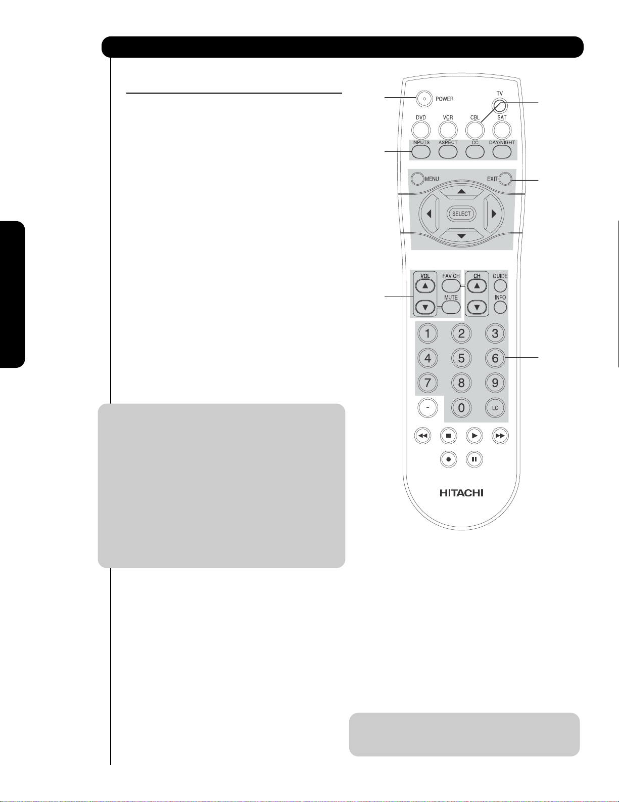
쐃 POWER button
Press this button to turn the TV set on or off when
쐃
쐇
쐄
쐏
쐆
쐋
쐂
쐎
쐅
the remote is in TV mode.
쐇 MODE buttons
These buttons allow the remote to control your TV,
VCR, DVD, Cable box/Satellite box depending on
which button is pressed. Refer to page 28~31 for
how to change between each of these modes.
쐋 DAY/NIGHT button
Press this button to toggle between Day (Normal),
Day (Dynamic) and Night picture mode settings. Select
DAY for day time viewing with more brightness and
contrast to compete with room light. Select NIGHT
for night time viewing with less brightness and
contrast for a more detailed picture (see page 34
for settings changes).
씈
쐊
쐉
쐈
The Remote Control
씉
씋
씈
씊
24
NOTE: For automatic DAY/NIGHT picture mode settings,
see page 48.
How to Use the Remote to Control Your TV
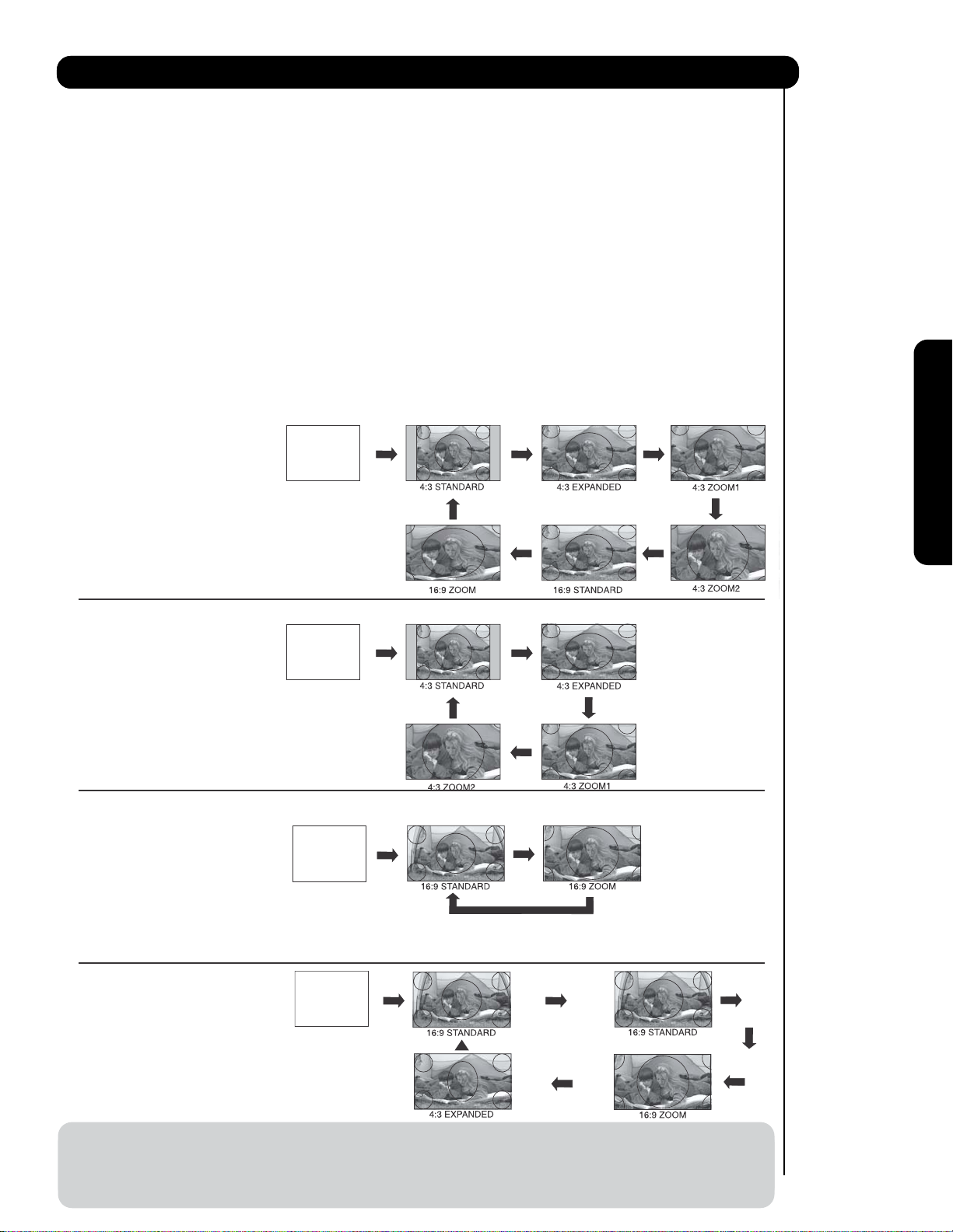
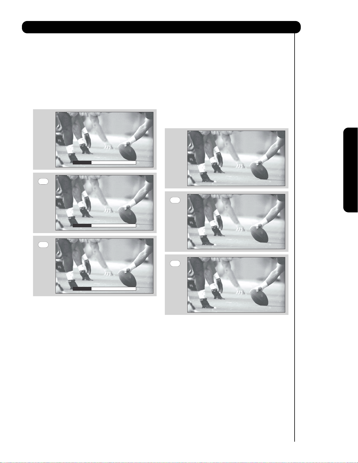
쐏
ASPECT button
Press this button to quickly change the picture format ASPECT ratio. Depending on the input signal format
received, the picture format ratio allows you to adjust the images through the following options.
4:3 STANDARD
Use this aspect mode to display conventional (4:3)
images. Side panels (gray areas) are placed to the
left and right of the image to preserve the original
aspect ratio of the source. Note: Use this mode for
only 15% of your total viewing time to prevent
uneven aging of the phosphors. Phosphors in the
lighted area of the picture will age more rapidly
than the gray areas.
4:3 EXPANDED
Use this aspect mode to display conventional (4:3)
sources by linearly increasing image expansion
from the center towards the edges of the display
area in order to fill it.
• Antenna-Analog Channel
• S-Video/Video Input
(Auto Aspect: Off)
• HDMI-480i/480p Input
(Auto Aspect: Off)
IMA GE INPUT
• Component-480i/480p
Input (Auto Aspect: Off)
Note: Please see Appendix A
on page 138-139.
4:3 ZOOM1/ZOOM2
Use these aspect modes to zoom in on
conventional (4:3) sources.
16:9 STANDARD 1
Use this aspect mode to display 16:9 sources like
HDTV and DVD’s preserving the original 16:9
aspect ratio showing 95% of the size.
16:9 STANDARD 2
Use this aspect mode to display 16:9 sources like
HDTV and DVD’s preserving the original 16:9
aspect ratio showing 100% of the size.
16:9 ZOOM
Use this aspect to Zoom-in once while in 16:9
aspect.
1
The Remote Control
• Antenna-Digital Channel (4:3)
• S-Video/Video 4:3/Letter
Input (Auto Aspect: On)
• HDMI-480i/480p 4:3/
Letter Input (Auto Aspect: On)
• Component-480i/480p 4:3/
Letter Input
(Auto Aspect: On)
Note: Please see Appendix A
on page 138-139.
• S-Video/Video 16:9 Input
(Auto Aspect: On)
• HDMI-480i/480p 16:9 Input
(Auto Aspect: On)
• Component-480i/480p
16:9 Input
(Auto Aspect: On)
Note: Please see Appendix A
on page 138-139.
• Antenna-Digital Channel (16:9)
• HDMI-720p/1080i/1080p Input
• Component-720p/1080i
Input
IMA GE INPUT
IMA GE INPUT
IMA GE INPUT
1
1
2
Note: Please see Appendix A
on page 138-139.
NOTE: 1. The Aspect Style in all video inputs have independent Aspect Style setting.
2. Vertical position adjustments are directly available when you choose 4:3 EXPANDED/ZOOM1/ZOOM2
or 16:9 ZOOM aspect style (see also page 36).
3. When displaying 16:9 STANDARD 2 it may appear lines at the edge of the picture this is normal operation of the TV
25
How to Use the Remote to Control Your TV
When an S-VIDEO Input is connected
to INPUT 1
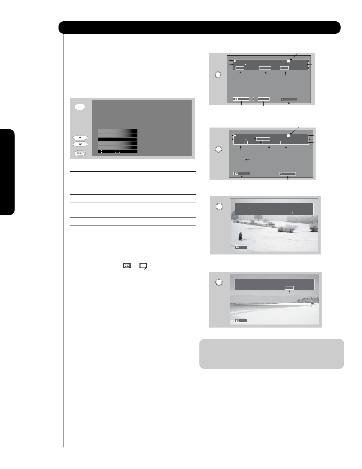
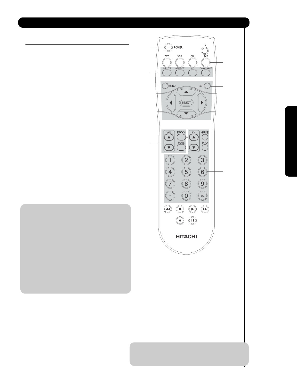
쐄
INPUTS button
When the remote control is in TV mode, press this
button to access the INPUTS menu. Use the
CURSOR and SELECT buttons to scroll and select
the inputs that are being used. Pressing the
Program Information
Program Run Time
INFO
INPUTS button repeatedly will also cycle through
the Inputs menu items. Then press the SELECT
button to select.
INPUTS
HDMI 2
HDMI-Front
Air / Cable
Input 1
Input 2
Move SEL Select
Program Information
Program Run Time
INFO
INPUT 1 Select to choose INPUT 1.
INPUT 2 Select to choose INPUT 2.
INPUT 3 Select to choose INPUT 3.
INPUT-FRONT Select to choose FRONT INPUT .
HDMI 1 Select to choose HDMI 1 INPUT.
The Remote Control
HDMI 2 Select to choose HDMI 2 INPUT.
INFO
HDMI-FRONT Select to choose FRONT HDMI INPUT.
AIR/CABLE Select between Air or Cable signal.
ANALOG CHANNELS
Show Name Air 8
3:00PM-
3:30PM KXYZ-HD
ST TV-G 480i 3:17PM
Audio
Broadcast
Auto STEREO
Closed
Caption setting
DIGITAL CHANNELS
Show Name Air 15-1
3:00PM-
ST 1080i 3:17PM
Audio
Broadcast
Auto
Closed
Caption setting
Broadcast
Rating
Audio Source
Selection
Digital Closed Caption
This icon will appear only when
receiving a Digital Broadcast with
Closed Captioning.
3:30PM KPBS-HD
REGION 5
DTvCC TV-G
Broadcast
Alternate
Rating
Rating
Program Desctiption
(Press INFO again for a more detailed description)
A
Picture Format
10:00 AM
Event timer
D
Picture Format
10:00 AM
Event timer
S-IN: 1
480i 3:17PM
Analog Channel
Digital channel
Main Picture Source
and channel indication
Broadcast channel
identication
Clock
Main Picture Source
and channel indication
Broadcast channel
identication
Clock
쐂
CLOSED CAPTIONS (CC) button
Use this button to display the dialogue, narration,
and/or sound effects of a television program or home
video which are displayed on the TV screen when
available. Your local TV program guide denotes
these programs as or .
쐆
MENU button
The MENU button will start the On-Screen Display.
쐊
GUIDE button
[Cable Box (CBL), Satellite Receiver (SAT)/
Set-Top-Box (STB) mode only]
The use of this button is only applicable when the
remote control is in (CBL) and (SAT/STB) mode.
Press this button to access the Channel Guide of
the (CBL), and (SAT/STB).
쐎
EXIT button
This button will exit all On-Screen Displays.
쐅
CURSOR buttons/SELECT button
All the On-Screen Display features can be set or
adjusted by using the CURSOR buttons and the
SELECT button, except for numeric entries. Press
the CURSOR buttons toward desired direction and
press the SELECT button to select.
Auto
When a Component Video: Y-PbPr
Input is connected to INPUT 3
INFO
Input Signal
Auto
Y-PBPR: 3
480i 3:17PM
Format
NOTE: 1. Press the INFO button again or the EXIT
button to return to normal viewing.
2. The Aspect setting will not be shown if
the channel is locked.
쐈
INFO button
Press this button when you want to check the
channel being received, the picture source, if the
channel has stereo (ST) or second audio program
(SA), the time, CHANNEL ID and if the TIMER is set.
26
How to Use the Remote to Control Your TV
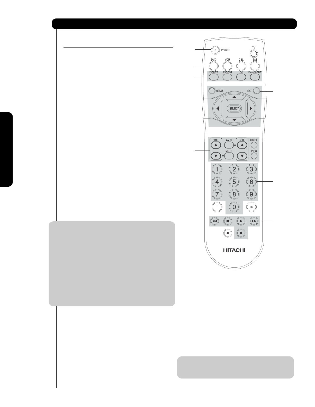
쐉
VOLUME (VOL), MUTE button
Press the VOLUME button (
or ) until you obtain
the desired sound level.
To reduce the sound to one half of normal volume
(SOFT MUTE) to answer the telephone, etc., press
the MUTE button. Press the MUTE button again to
turn the sound off completely (MUTE). To restore
the sound, press the MUTE button one more time,
or VOL UP (
MUTE
).
Volume 8
Press the FAV CH button to switch to Favorite
(FAV) channel mode. You will know you are in
Favorite Channel mode when (FAV) is displayed
and the displayed channel is GREEN. Press it
again to return to your regular tuned channels. You
can add any channel to your Favorite channel list
by pressing and holding down the FAV CH button
until the displayed channel turns from WHITE to
highlighted GREEN. You can also delete a channel
from your favorite channel list by pressing and
holding down the FAV CH button until the
displayed channel turns highlighted GREEN to
WHITE.
The Remote Control
Cable 6
FAV CH
FAV Cable 6
Soft Mute 8
MUTE
Mute 8
Closed Captioning will display automatically when
MUTE/SOFT MUTE is on and Closed Caption is set
to AUTO (see page 53).
When the TV power is turned off at a volume level
31 or greater, the volume level will default to 30
when the TV is turned on. However, if it is set to a
level 30 or less, the volume level will be at the level
it was set when the TV is turned on.
CHANNEL SELECTOR/FAVORITE CHANNEL
씈
(FAV CH) buttons
The CHANNEL SELECTOR buttons are used to
select channels, lock access code, etc. Use the
CHANNEL SELECTOR buttons to enter one, two,
or three numbers to select channels. Enter 0 first
for channels 1 to 9, or simply press the single digit
channel you wish to tune then wait a few seconds
for the TV to tune. Channel selection may also be
performed by CHANNEL (CH) UP (
CHANNEL (CH) DOWN (
).
) or
FAV CH
씉
(-) DASH button
Cable 6
Use the (-) DASH button with the CHANNEL
SELECTOR buttons to enter Digital Channels that
have subchannel numbers indicated by (-) DASH
(example 15-1).
씊
LAST CHANNEL (LC) button
Press this button to toggle between the current and
last channel viewed.
씋
RECORD button
Press twice (two times) to record programs when
the remote is in VCR mode.
27
The Remote Control for Cable Box Functions
OPERATING THE PRECODED
FUNCTION FOR YOUR CABLE BOX.
This remote is designed to operate different types of
cable boxes. You must first program the remote to
match the remote system of your cable box (refer
below for pre-codes).
1. Turn ON your cable box.
쐇
쐋
쐃
2. To switch to Cable (CBL) pre-coded mode, press
and release the CABLE (CBL) button.
3. Hold down the CBL button on the remote and
enter the two digit preset code that matches your
cable box, as shown below. Release the CBL
button.
4. Aim the remote at the cable box and press the
POWER button. The remote will turn off your cable
box when the correct two digit preset code is
entered. When this occurs, the remote control is
programmed for your cable box. If the cable box
does not turn off, try a different two digit preset
The Remote Control
code.
5. The remote will now control your Cable box.
NOTE: 1. If your cable box cannot be operated after
performing the above procedures, your
cable box code has not been precoded
into the remote.
2. In the unlikely event that your cable box
cannot be operated after performing the
above procedures, please consult your
cable box operating guide.
3. The remote control will remember the
codes you have programmed until the
batteries are removed from the remote
control. After replacing the batteries
repeat the entire programming procedure
as stated above.
쐃 CABLE (CBL) button
This button allows the remote to control your cable
box by setting it to CABLE mode.
쐇 PRECODED CABLE BOX buttons
These buttons transmit the chosen precoded cable
codes.
쐋 EXCLUSIVE TV buttons
These buttons are for operating the TV.
쐋
CABLE BRAND ANALOG TYPE CODES
HAMLIN......................................................22, 23, 24, 25
JERROLD .................... 00, 01, 02, 03, 04, 05, 06, 07,21
OAK..................................................................26, 27, 28
PANASONIC.................................................... 18, 19, 20
PIONEER ................................................................13, 14
SCIENTIFIC ATLANTA......................................08, 09, 10
TOCOM ..................................................................15, 16
ZENITH...................................................................11, 12
G.I. ..............................................................................17
CABLE BRAND DIGITAL TYPE CODES
PIONEER..............................................................29
SCIENTIFIC ATLANTA ..............................................30
MY CABLE BOX CODE IS: _______________________
NOTE: Refer to instruction manual of the Cable Box
for operation of the buttons exclusively for
the Cable Box.
쐇
쐇
28
The Remote Control for Set-Top Box/Satelite Receiver Functions
OPERATING THE PRECODED FUNCTION FOR
YOUR SET-TOP-BOX/SATELLITE RECEIVER.
This remote is designed to operate different types of
set-top-box/satellite systems. You must first program
the remote to match the remote system of your settop-box/satellite systems (refer below for pre-codes).
1. Turn ON your set-top-box/satellite systems.
2. To switch to set-top-box/satellite (STB) pre-coded
mode, press and release the SAT button.
쐇
쐃
쐋
쐇
3. Hold down the SAT button on the remote and enter
the two digit preset code that matches your settop-box/satellite receiver, as shown below. Release
the SAT button.
4. Aim the remote at the set-top-box/satellite receiver
and press the POWER button. The remote will turn
off your set-top-box/satellite receiver when the
correct two digit preset code is entered. When this
occurs, the remote control is programmed for your
set-top-box/satellite receiver. If the set-top-box/
satellite receiver does not turn off, try a different
two digit preset code.
5. The remote will now control your set-top-box/
satellite receiver.
NOTE: 1. If your set-top-box/satellite receiver
cannot be operated after performing the
above procedures, your set-topbox/satellite receiver code has not been
precoded into the remote.
2. In the unlikely event that your set-topbox/satellite receiver cannot be operated
after performing the above procedures,
please consult your set-top-box/satellite
receiver operating guide.
3. The remote control will remember the
codes you have programmed until the
batteries are removed from the remote
control. After replacing the batteries
repeat the entire programming procedure
as stated above.
쐃 SAT (Set-Top-Box/Satellite) button
This button allows the remote to control your settop-box/satellite receiver by setting it to SET-TOPBOX/SATELLITE mode.
쐇 PRE-CODED SET-TOP-BOX/SATELLITE
RECEIVER buttons
These buttons transmit the chosen pre-coded settop-box/satellite codes.
쐋 EXCLUSIVE TV buttons
These buttons are for operating the TV.
The Remote Control
쐋
쐇
SATELLITE BRAND CODES
2006 DIRECT TV ........................................................ 09
ECOSTAR .....................................................................03
HITACHI....................................................................... 00
HUGHES ......................................................................04
RCA ..............................................................................01
SONY ...........................................................................02
SET TOP BOX BRAND CODES
PANASONIC.................................................................05
RCA ............................................................................. 06
SAMSUNG ...................................................................07
ZENITH.........................................................................08
MY SATELLITE RECEIVER/
SET TOP BOX CODE IS: _________________________
NOTE: Refer to instruction manual of the set-top-
box/satellite receiver for operation of the
buttons exclusively for the set-topbox/satellite receiver.
29
The Remote Control for DVD Functions
OPERATING THE PRECODED
FUNCTION FOR YOUR DVD PLAYER.
This remote is designed to operate different types of
DVD players. You must first program the remote to
match the remote system of your DVD player (refer
below for pre-codes).
쐇
쐃
쐋
1. Turn ON your DVD player.
2. To switch to DVD pre-coded mode, press and
release the DVD button.
3. Hold down the DVD button on the remote and
enter the two digit preset code that matches your
DVD player, as shown below. Release the DVD
button.
4. Aim the remote at the DVD player and press the
POWER button. The remote will turn off your DVD
player when the correct two digit preset code is
entered. When this occurs, the remote control is
The Remote Control
programmed for your DVD player. If the DVD player
does not turn off, try a different two digit preset
code.
5. The remote will now control your DVD player.
쐋
쐇
쐇
쐇
NOTE: 1. If your DVD player cannot be operated
after performing the above procedures,
your DVD player’s code has not been
precoded into the remote.
2. In the unlikely event that your DVD player
cannot be operated after performing the
above procedures, please consult your
DVD player operating guide.
3. The remote control will remember the
codes you have programmed until the
batteries are removed from the remote
control. After replacing the batteries
repeat the entire programming procedure
as stated above.
쐃 DVD button
This button allows the remote to control your DVD
player by setting it to DVD mode.
쐇 PRECODED DVD Buttons
These buttons transmit the chosen precoded DVD
codes.
쐋 EXCLUSIVE TV Buttons
These buttons are for operating the TV.
DVD BRAND CODES
APEX ............................................................................10
GO VIDEO ................................................................... 09
HITACHI........................................................................00
KENWOOD ...................................................................11
PANASONIC.................................................................02
PIONEER ..................................................................... 03
RCA ............................................................................. 04
SAMSUNG ...................................................................06
SANYO .........................................................................07
SONY ...........................................................................01
TOSHIBA ......................................................................05
MY DVD PLAYER CODE IS: ______________________
NOTE: Refer to instruction manual of the DVD player
for operation of the buttons exclusively for
the DVD player.
30
 Loading...