


REPAIR
Parts
309379
This manual contains important
warnings and information.
READ AND KEEP FOR REFERENCE.
INSTRUCTIONS
HydraMax Sprayers
HydraMax 225
3600 psi (248 bar, 24.8 MPa) Maximum Working Pressure)
Model Series Direct
Immersion
233640
233641 B X
233642
233643 B X X
B
B
X
X X
HydraMax 300
3600 psi (248 bar, 24.8 MPa) Maximum Working Pressure)
30 Gallon
Suction
RACR X,
Silver Gun
and Hose
Rev. F
Model Series Direct
Immersion
233650 B X
233651 B X X
30 Gallon
Suction
RAC X,
Silver Gun
and Hose
HydraMax 350
4000 psi (276 bar, 27.6 MPa) Maximum Working Pressure)
Model Series Direct
Immersion
233660 B X
233661 B X X
30 Gallon
Suction
GHD, Texture Gun
and Hose
Table of Contents
Warnings 2. . . . . . . . . . . . . . . . . . . . . . . . . . . . . . . . . . . . . .
General Repair Information 3. . . . . . . . . . . . . . . . . . . . . .
Maintenance 4. . . . . . . . . . . . . . . . . . . . . . . . . . . . . . . . . . .
Troubleshooting 5. . . . . . . . . . . . . . . . . . . . . . . . . . . . . . . .
Hydraulic Pump 6. . . . . . . . . . . . . . . . . . . . . . . . . . . . . . . .
Fan Belt 8. . . . . . . . . . . . . . . . . . . . . . . . . . . . . . . . . . . . . . .
Pressure Control 9. . . . . . . . . . . . . . . . . . . . . . . . . . . . . . .
DTS Error Codes 11. . . . . . . . . . . . . . . . . . . . . . . . . . . . . .
Engine 12. . . . . . . . . . . . . . . . . . . . . . . . . . . . . . . . . . . . . . .
Displacement Pump 15. . . . . . . . . . . . . . . . . . . . . . . . . . .
Hydraulic Motor 13. . . . . . . . . . . . . . . . . . . . . . . . . . . . . . .
GRACO INC. P.O. BOX 1441 MINNEAPOLIS, MN 55440–1441
COPYRIGHT 2001, GRACO INC.
Graco Inc. is registered to I.S. EN ISO 9001
ti1431a
Related Manuals
Operation 309378. . . . . . . . . . . . . . . . . . . . . . . . . .
Displacement Pump 309277. . . . . . . . . . . . . . . . .
Spray Gun 309740. . . . . . . . . . . . . . . . . . . . . . . . .
Spray Tip 309640. . . . . . . . . . . . . . . . . . . . . . . . . . .
AutoClean 309380, 309278. . . . . . . . . . . . . . . . .
Drain Valve 308961. . . . . . . . . . . . . . . . . . . . . . . .
Board Repair Kit 244981 309452. . . . . . . . . . . . .
Directional Valve and Hydraulic Motor Switches 14. . .
HydraMax 225 Sprayers Parts Drawing 16. . . . . . . . . . .
HydraMax 225 Sprayers Parts List 17. . . . . . . . . . . . . . .
HydraMax 300/350 Sprayers Parts Drawing 22. . . . . . .
HydraMax 300/350 Sprayers Parts List 23. . . . . . . . . . .
HydraMax 300/350 Sprayers Parts List 23. . . . . . . . . . .
HydraMax Sprayers with Spray Gun and Hoses 30. . .
Technical Data 31. . . . . . . . . . . . . . . . . . . . . . . . . . . . . . . .
Graco Phone Number 31. . . . . . . . . . . . . . . . . . . . . . . . . .
Graco Warranty 32. . . . . . . . . . . . . . . . . . . . . . . . . . . . . . .

WARNING
ADVERTÊNCIA
Fire and explosion hazard: Solvent and paint fumes can ignite or
explode.
To help prevent a fire and explosion:
Use only in an extremely well ventilated area.
Eliminate all ignition sources; such as pilot lights, cigarettes and
plastic drop cloths (static arc hazard). Do not plug or unplug power
cords or turn lights on or off in spray area.
Ground Sprayer, object being sprayed, paint and solvent pails.
Hold gun firmly to side of grounded pail when triggering into pail.
Use only conductive airless paint hose.
Do not use 1,1,1-trichloroethane, methylene chloride, other
halogenated hydrocarbon solvents or fluids containing such
solvents in pressurized aluminum equipment. Such use could
result in a chemical reaction, with the possibility of explosion.
To reduce risk of electric shock, use grounded outlet only. Shut
OFF and unplug when repairing.
Fluid injection and high pressure hazard: High pressure spray or
leaks can inject fluid into the body.
To help prevent injection, always:
Engage trigger safety latch when not spraying.
Keep clear of nozzle and leaks.
Never spray without a tip guard.
Do PRESSURE RELIEF if you stop spraying or begin servicing
sprayer.
Do not use components rated less than sprayer Maximum
Working Pressure.
Never allow children to use this unit.
If high pressure fluid pierces your skin, the injury might look like
“just a cut”. But it is a serious wound! Get immediate medical attention.
Perigo de incêndio e explosão: os solventes e os vapores da pintura
poderão explodir ou incendiar.
Para ajudar a evitar incêndio e explosão:
Utilize unicamente em áreas extremamente bem ventiladas.
Elimine todas as fontes de ignição, tais como luzes piloto, cigarros e
arcos de estática resultantes dos plásticos de proteção. Não ligue nem
desligue os cabos de alimentação ou as luzes numa área de
pulverização.
Ponha em contato com a terra o pulverizador, o objeto a ser
pulverizado, e os baldes de tinta e de solventes.
Segure a pistola firmemente de encontro ao lado do balde em contato com
a terra, quando estiver descarregando para dentro do mesmo.
Utilize somente tubos flexíveis condutores para pintura a alta pressão.
Não utilize 1,1,1-tricloroetano, cloreto de metileno, outros solventes de
hidrocarbonetos halogenados ou líquidos contendo tais solventes em
equipamento de alumínio pressurizado. Tal utilização poderá
resultar numa reação química, com possibilidade de explosão.
Para reduzir o risco de choque elétrico, use a tomada aterrada
somente. Feche FORA e desconecte ao reparar.
Perigo de injeção de líquidos à alta pressão: a pulverização ou vazamentos à alta pressão podem injetar líquido no corpo.
Para ajudar a evitar injeção de líquido, faça sempre o seguinte:
Engate o trinco de segurança do gatilho quando não estiver pulverizando.
Mantenha-se afastado dos bocais e locais onde há vazamentos.
Nunca pulverize sem que haja uma proteção na extremidade.
ALIVIE A PRESSÃO quando parar de pulverizar e antes de iniciar a
manutenção do pulverizador.
Não utilize componentes com uma classificação inferior à do pulverizador
Pressão Máxima de Trabalho.
Nunca permita que crianças utilizem esta unidade.
Se o líquido a alta pressão penetrar na sua pele, o ferimento poderá
parecer “simplesmente um corte”. Mas é um ferimento grave! Procure o
médico imediatamente.
MISE EN GARDE
Danger d’incendie et d’explosion : les gaz de solvant et de peinture
peuvent s’enflammer ou exploser.
Pour éviter les risques d’incendie et d’explosion :
N’utiliser l’appareil que dans une zone extrêmement bien aérée.
Éliminer toute source d’inflammation ; telle que veilleuses, cigarettes et
arcs d’électricité statique créés par les toiles de peintre en plastique. Ne
pas brancher et débrancher de cordons électriques, ou allumer et
éteindre des lumières dans la zone de pulvérisation.
Mettre à la terre le pulvérisateur, l’objet à pulvériser ainsi que les seaux
de peinture et de solvants.
Tenir le pistolet fermement contre la paroi d’un seau mis à la terre lorsqu’on
pulvérise dans le seau.
N’utiliser qu’un flexible pour peinture pulvérisée sans air.
Ne jamais utiliser de trichloroéthane 1,1,1, de chlorure de méthylène,
d’autres solvants à base d’hydrocarbures halogénés, ni de produits
contenant de tels solvants dans un équipement sous pression en aluminium. Cela pourrait provoquer une réaction chimique avec risque d’explosion.
Pour réduire le risque de décharge électrique, employez la sortie au
sol seulement. Coupez et débranchez quand la réparation.
Danger d’injection de fluide et haute pression : la pulvérisation sous
haute pression ou les fuites peuvent injecter des fluides dans le corps.
Pour éviter les risques d’injection, toujours :
Bloquer le loquet de sécurité de la gâchette à la fin de la pulvérisation.
Se tenir loin de la buse et des fuites.
Ne jamais pulvériser sans anti-gouttes.
DÉCHARGER LA PRESSION à la fin de la pulvérisation ou avant de
réparer le pulvérisateur.
Ne pas utiliser de composants dont la pression nominale est inférieure à
la pression maximale de service du système.
Ne jamais permettre aux enfants d’utiliser cet appareil.
Si un fluide haute pression perce la peau, la blessure peut paraître
une “simple coupure” Mais il s’agit bien d’une lésion grave! Consulter
immédiatement un médecin.
ADVERTENCIA
Peligro de incendio o explosión: Los gases de los disolventes y de la
pintura pueden inflamarse o provocar una explosión.
Para prevenir incendios y explosiones:
Use únicamente en un área muy bien ventilada.
Suprima todas las fuentes de ignición; como luces piloto, cigarrillos y
arcos estáticos de carpetas plásticas para protección contra pintura. No
enchufe ni desenchufe cables de alimentación ni apague ni encienda las
luces en un área de pulverización.
Ponga a tierra el pulverizador, el objeto que recibe el chorro pulverizado,
las cubetas de pintura y disolvente.
Sostenga firmemente la pistola a un lado de la cubeta puesta a tierra
cuando dispare dentro de ella.
Use solamente mangueras para pintura conductora sin aire.
No utilice nunca tricloretano-1,1,1, cloruro de metileno ni otros
disolventes a base de hidrocarburos halógenos o fluidos que contengan
dichos disolventes en un equipo a presión de aluminio. El uso de estas
sustancias puede provocar una intensa reacción química, con riesgos
de explosión.
Para reducir el riesgo de la descarga eléctrica, utilice el enchufe
puesto a tierra solamente. Apague y desenchufe al reparar.
Peligro de inyección de fluido y alta presión: por la pulverización o las
filtraciones a alta presión se pueden inyectar fluidos en el organismo.
Para prevenir la inyección en la piel, siempre:
Enganche el seguro del gatillo cuando no use el pulverizador.
No se acerque a la boquilla ni a las filtraciones.
Nunca aplique fluido pulverizado sin un guardaboquilla.
Realice el ALIVIO DE PRESIÓN si deja de pulverizar fluido o repara el
pulverizador.
No use componentes de capacidad nominal inferior a la presión máxima
de operación del pulverizador.
No permita que niños usen esta unidad.
Si fluido de alta presión le penetra la piel, la lesión podría parecer “sólo
un corte”. ¡Es una lesión seria! Consulte de inmediato al médico.
3093792
General Repair Information
WARNING
MOVING PARTS HAZARD
To reduce risk of serious injury, do not
touch moving parts with fingers or tools
while testing repair. Shut off sprayer
when repairing. Install all covers, gaskets, screws and washers before operating sprayer.
CAUTION
To reduce risk of pressure control malfunction:
Use needle nose pliers to disconnect wires. Never
pull on wire, pull on connector.
Mate wire connectors properly. Center flat blade of
insulated male connector in female connector.
Route wires carefully to avoid interference with
other connections of pressure control. Do not pinch
wires between cover and control box.
1. Keep all screws, nuts, washers, gaskets, and
electrical fittings removed during repair procedures. These parts are not normally provided with
replacement assemblies.
WARNING
HOT SURFACES HAZARD
EXPLOSION HAZARD
Hydraulic reservoir and engine may be
very hot during operation and could burn
skin if touched.
Flammable materials spilled on hot
engine could cause fire or explosion.
Have fan shroud in place during operation to reduce risk of burns, fire or explosion.
4. Install fan shroud before operation of sprayer
and replace if damaged. Fan shroud directs cooling air around reservoir to prevent overheating. It
can also reduce risk of burns, fire, explosion and
pinching; see preceding WARNING.
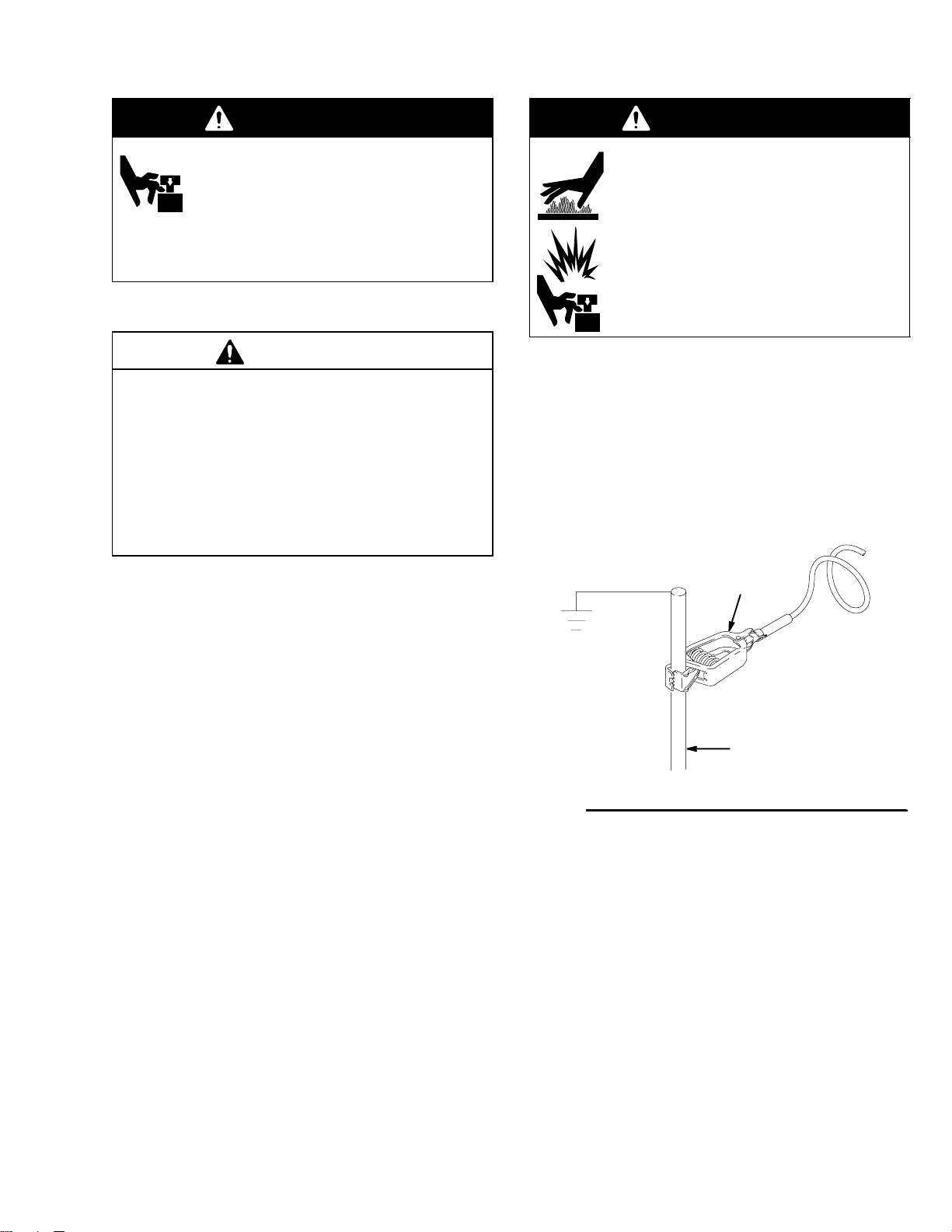
Grounding
Ground sprayer with grounding clamp to earth ground for
safe sprayer operation. Fig. 1.
grounding
clamp
2. Test repair after problem is corrected.
3. If sprayer does not operate properly, review
repair procedure to verify procedure was done
correctly. If necessary, see Troubleshooting Guide,
page 5, for other possible solutions.
Fig. 1
water pipe, steel
sign post, or metal
light pole
06250
3309379

Maintenance
WARNING
INJECTION HAZARD
The system pressure must be manually
relieved to prevent the system from
starting or spraying accidentally. Fluid
under high pressure can be injected through the
skin and cause serious injury. To reduce the risk of
an injury from injection, splashing fluid, or moving
parts, follow the Pressure Relief Procedure
whenever you:
are instructed to relieve the pressure,
stop spraying,
check or service any of the system equipment,
or install or clean the spray tip.
Pressure Relief Procedure
DAILY: Check engine oil level and fill as necessary.
DAILY: Check hydraulic oil level and fill as neces-
sary.
DAILY: Check hose for wear and damage.
DAILY: Check gun safety for proper operation.
DAILY: Check pressure drain valve for proper opera-
tion.
DAILY: Check and fill the gas tank.
DAILY: Check that displacement pump is tight.
DAILY: Check level of TSL in displacement pump
packing nut. Fill nut, if necessary. Keep TSL in nut to
help prevent fluid buildup on piston rod and premature
wear of packings and pump corrosion.
1. Lock gun trigger safety.
2. Turn engine ON/OFF switch to OFF.
3. Move pump switch to OFF and turn pressure
control knob fully counterclockwise.
4. Unlock trigger safety. Hold metal part of gun firmly
to side of grounded metal pail, and trigger gun to
relieve pressure.
5. Lock gun trigger safety.
6. Open pressure drain valve. Leave valve open until
ready to spray again.
If you suspect that the spray tip or hose is completely
clogged, or that pressure has not been fully relieved
after following the steps above, VERY SLOWLY
loosen tip guard retaining nut or hose end coupling to
relieve pressure gradually, then loosen completely.
Now clear tip or hose.
CAUTION
For detailed engine maintenance and specifications,
refer to separate Honda Engines Owner’s Manual,
supplied.
AFTER THE FIRST 20 HOURS OF OPERATION:
Drain engine oil and refill with clean oil. Reference
Honda Engines Owner’s Manual for correct oil viscosity.
WEEKLY: Remove engine air filter cover and clean
element. Replace element, if necessary. If operating in
an unusually dusty environment: check filter daily and
replace, if necessary.
Replacement elements can be purchased from your
local HONDA dealer.
WEEKLY/DAILY: Remove any debris or media from
hydraulic rod.
AFTER EACH 100 HOURS OF OPERATION:
Change engine oil. Reference Honda Engines Owner’s
Manual for correct oil viscosity.
SEMI-ANNUALLY:
Check belt tension, page 8; adjust if necessary.
YEARLY OR 2000 HOURS:
Replace hydraulic oil and filter element with Graco
hydraulic oil 169236 (5 gallon/20 liter) or 207428 (1
gallon/3.8 liter) and filter element 244990; page 6.
SPARK PLUG: Use only BPR6ES (NGK) or
W20EPR–U (NIPPONDENSO) plug. Gap plug to
0.028 to 0.031 in. (0.7 to 0.8 mm). Use spark plug
wrench when installing and removing plug.
3093794
Troubleshooting
WARNING
INJECTION HAZARD
To reduce risk of serious injury, when instructed to relieve pressure, follow steps 1. – 6.; page 4.
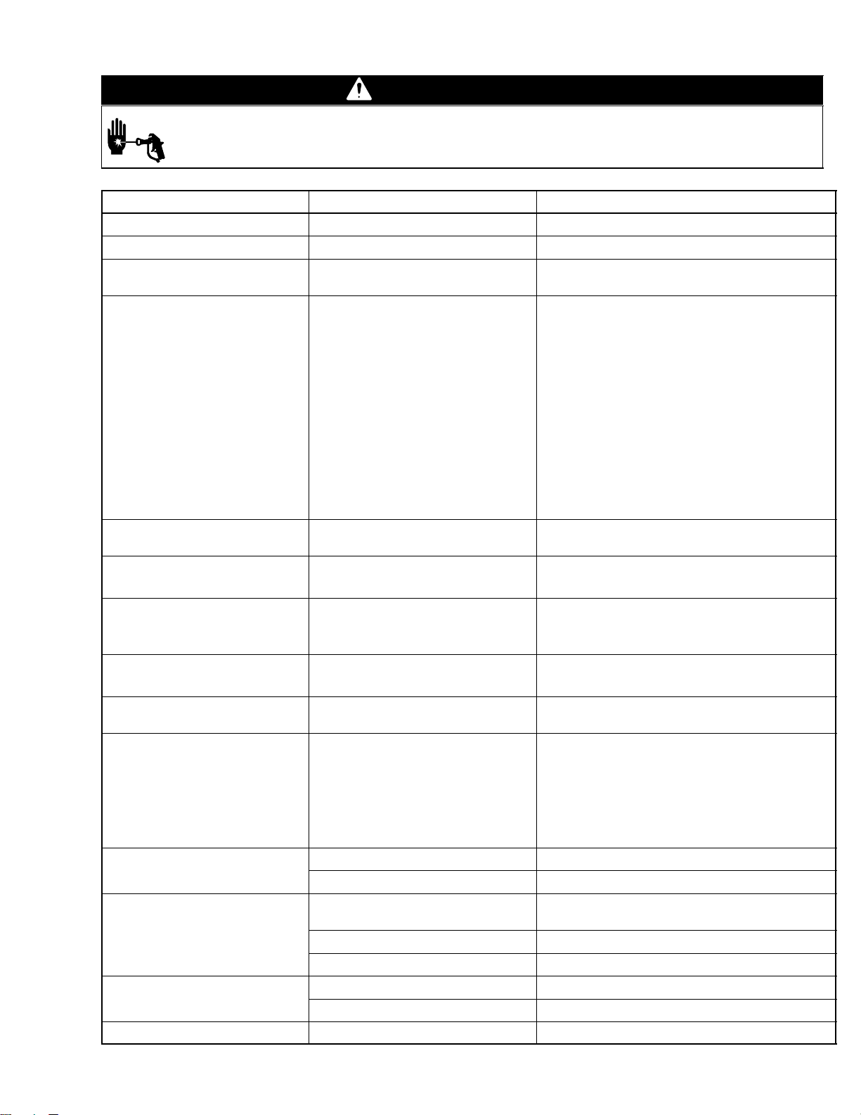
PROBLEM CAUSE SOLUTION
Gas engine pulls hard (won’t start) Hydraulic pressure is too high Turn hydraulic pressure knob ccw to lowest setting
Gas engine will not start Switch OFF, low oil, no gasoline Consult engine manual, supplied
Gas engine races to high rpm at
stall – bogs down on operation
Gas engine operates, but
displacement pump does not
Displacement pump stays in downstroke
Displacement pump operates, but
output is low on upstroke
Displacement pump operates but
output is low on downstroke and/
or on both strokes
Paint leaks and runs over side of
wetcup
Excessive leakage around
hydraulic motor piston rod wiper
Fluid delivery is low Pressure setting too low
The sprayer overheats Cooler is damaged Replace
Spitting from gun Air in fluid pump or hose Check for loose connections on siphon assembly,
DTS does not display Loose wiring Remove cover and correct poor connections
DTS displays error codes Various over-pressure conditions Page 11
Engine governor worn Contact Honda Engine Service Center
Directional valve not switching Turn pump switch OFF, then ON; manual 309379
Pump switch is OFF Turn pump switch ON
Pressure setting too low Increase pressure, manual 309378
Displacement pump outlet filter (if
used) is dirty or clogged
Tip or tip filter (if used) is clogged Remove tip and/or filter and clean
Hydraulic fluid too low Shut off sprayer immediately. Add fluid*; page 4.
Hydraulic pump worn or damaged Bring sprayer to Graco distributor for repair
Displacement pump rod seized by
dried paint
Powered off sprayer with engine ON/
OFF. Magnet below bottom sensor.
Piston ball check not seating properly.
Piston packings worn or damaged.
Piston packings worn or damaged.
Intake valve ball check not seating
properly.
Loose wet–cup
Throat packings worn or damaged
Piston rod seal worn or damaged Replace these parts; manual 309379
Displacement pump outlet filter (if
used) is dirty or clogged
Intake line to pump inlet is not tight
Hydraulic motor is worn or damaged
Large pressure drop in fluid hose
Oil level is low Fill with oil. See page 6.
Loose intake suction Tighten
Fluid supply is low or empty Refill supply container
Bad LCD or board Bring sprayer to Graco distributor for repair
Clean the filter
Service pump; manual 309277
Start engine. Turn pump switch OFF, then ON. Increase pressure.
Service piston ball check; manual 309277.
Replace packings; manual 309277.
Remove clip and retighten or replace packings;
manual 309277.
Service intake valve ball check; manual 309277
Tighten just enough to stop leakage
Replace packings; manual 309277
Increase pressure, manual 309378
Clean filter
Tighten
Bring sprayer to Graco distributor for repair
Use larger diameter hose
tighten, then reprime pump
*Check hydraulic fluid level often. Do not allow it to become too low. Use only Graco approved hydraulic fluid, page 4.
5309379

Hydraulic Pump
Removal
1.
Let hydraulic system cool before beginning service.
2. Fig 2. Use 3.5 gallon container to catch hydraulic
fluid. Remove reservoir drain plug (133) and drain
hydraulic fluid.
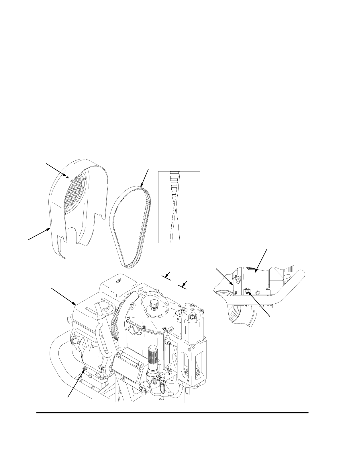
3. Remove two screws (141) and fan shroud (23).
4. Remove eight screws (136), washers (81) and
reservoir cover (50).
5. Remove cooler clip screw (141).
6. Loosen four engine mounting fasteners and belt
tension adjustment screw (Fig. 3). Slide engine to
left (rear view) to relieve tension on belt (6). Remove belt.
Relieve pressure; page 4.
4. Fig 2. Set hydraulic pump (2) down and toward
rear of reservoir to install.
5. Install two pump bolts (94) in reservoir with copper
washers (64) on outside under screw heads.
Torque to 31–35 ft-lb.
6. Connect strainer (25) to elbow (139).
7. Connect elbow (54) to hydraulic motor manifold
(46). Connect hydraulic tube (52) to elbow (54).
Torque hex nuts on elbows (139) and (53) to
38 – 42 ft-lb.
8. Insert spring (D) into coupler (E) and put holder (C)
on exposed end of spring. Slide assembly (D, E,
C) over compensator stem (A). Align flat on
compensator stem with set screw (B). Hold compensator stem knob and torque set screw to 90
in-lb.
9. Install key (F) on pump shaft and install fan (19)
with two set screws (18). Fan hub must overhang
shaft approximately 0.20 in.
7. Remove two set screws (18) and fan (19).
8. Disconnect hydraulic tube (52) from elbow (54)
and hydraulic motor manifold (46).
9. Disconnect strainer (25) with elbows (58, 30)
assembled, from elbow (139).
10. Remove case drain tube (67).
11. Turn compensator stem (A) clockwise until stop.
Loosen set screw (B). Pull compensator stem out.
Remove holder (C), spring (D) and coupler (E).
12. Remove two pump bolts (94) from reservoir.
13. Lift hydraulic pump (2) up and toward front of
reservoir to remove.
Installation
1. Transfer fittings (53, 139) to new pump (2).
2. Place strainer (25) with fittings (30, 58) assembled,
into reservoir prior to installing pump.
3. Attach hydraulic tube (52) to pump (2) with elbow
(53). Install new o-ring (56) on hydraulic pump
flange
10. Install belt (6). Do Fan Belt Installation, page 8.
11. Install reservoir drain plug (133).
a. Fill pump with hydraulic oil.
b. Install case drain elbow (24) and tube (67).
c. Fill reservoir to fill level (approximately 2.75
gallons) with Graco hydraulic fluid.
12. Install reservoir cover (50) with eight washers (81)
and screws (136). Torque to 95–100 in-lb.
13. Install cooler clip screw (141).
14. Install fan shroud (23) with two screws (141).
15. Verify hydraulic pump operation:
a. Run sprayer with hydraulic motor slow stroking
and minimum pressure for 2 minutes.
b. Set hydraulic pressure at maximum. Turn
pump switch OFF.
c. Check for hydraulic oil leaks. Add hydraulic oil
as needed.
3093796

136136
81
141
23
Bottom View
50
6
19
18
56
24
67
F
2
E
C
A
B
D
141
52
54
53
94
6425
139
30
Fig. 2
58
133
46
TI11476b
Engine mounting
fasteners
7309379
Fan Belt
Removal
1. Fig. 3. Remove two screws (141) and slide shroud
(23) up and off of sprayer.
2. Loosen four fasteners on underside of engine (1).
3. Loosen belt tension adjustment screw.
4. Slide engine to left (rear view) to remove tension
on belt.
5. Remove belt (6).
141
6
Installation
1. Thread new belt around bottom drive pulley, and
install on fan pulley.
a. lightly snug four engine fasteners.
b. Loosen jam nut on belt tension adjustment
screw and slowly tighten screw. (This adjusts
belt tension.) Tighten jam nut after belt is
properly adjusted.
2. Adjust belt tension to be able to twist belt
about 45.
3. Align engine flush to front of alignment lip. Tighten
four fasteners at base of engine.
4. Install fan shroud (23) with two screws (141).
45
Twist
23
Fig. 3
Engine
Alignment
Flange
A
1
95
A
Belt Tension
Adjustment Screw
View A – A
ti1475a
3093798
Pressure Control
Display and Control Board
Removal
1.
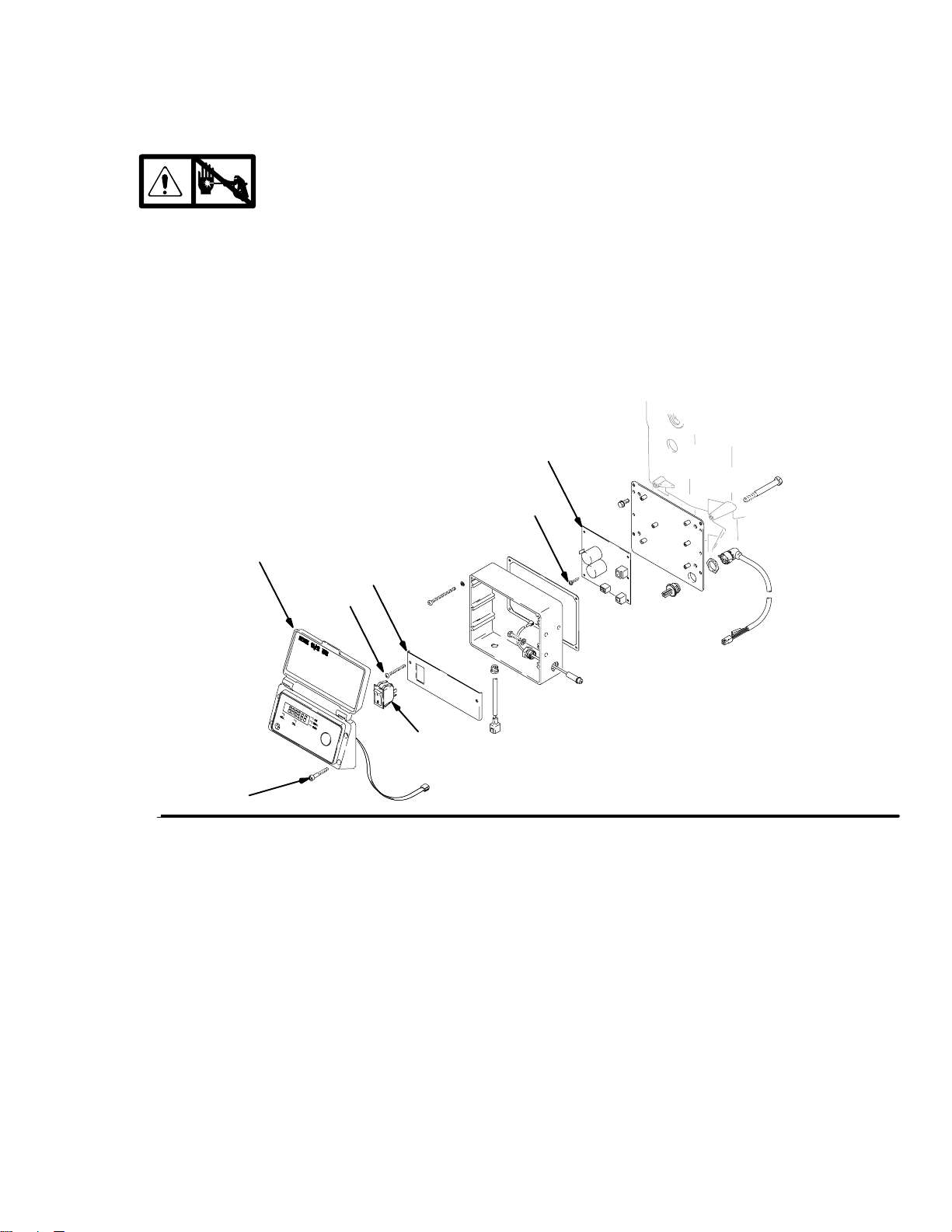
2. Fig. 4. Remove four screws (100) and pressure
control cover (99). Disconnect display connector
from control board and remove display.
3. Disconnect wiring from switch (93).
4. Remove two screws (74) and switch panel (97).
5. Remove six screws (72).
Relieve pressure; page 4.
99
97
74
6. Disconnect leads and remove control board (315).
Installation
1. Install control board (315) (Manual 309452) and
connect leads.
2. Install six screws (72).
3. Install switch panel (97) with two screws (74).
4. Connect wiring to switch (93).
5. Install display and connect display connector to
control board. Install pressure control cover (99)
with four screws (100).
315
72
Fig. 4
93
ti1430a
100
9309379

Pressure Control
Digital Tracking System (DTS)
The DTS contains stored data to assist with job control, troubleshooting and maintenance.
General
The DTS has Main and Secondary operation menus:
Main Menu – Three modes/displays (four if
AutoClean is installed). The sprayer automatically
enters the Main Menu when the engine starts.
Pressure – Fluid pressure at sprayer. Pressure
is default display and is displayed at start–up.
Job Gallon – Job material pumped above 1000
psi (70 bar) since Job Gallon was last reset to
zero. Counts in 1 gallon or 10 liter increments.
Lifetime Gallon – Total material pumped above
1000 psi (70 bar) over lifetime of sprayer.
Counts in 1 gallon or 10 liter increments.
AutoClean Shut-Off Timer – Automatically
shuts pump off after approximately 4.5 gallons
of material have been pumped. Used with
AutoClean kit 245159
Lifetime Gallon Counter – Total material
pumped at all pressures over the lifetime of
the sprayer. Counts in 1 gallon or 10 liter
increments.
Diagnostic Tools – uP and dn displays indicate
whether current is present at proximity sensors
Diagnostics
UP
UP – displays to indicate no current is present
at electronic valve
Pump moves to up position, and gal LED light
indicates a complete circuit to upper proximity
sensor
dn
dn – displays to indicate current is present at
electronic valve
Pump moves to down position, and liter LED
lights indicates a completed circuit to lower
proximity sensor
Secondary Menu – Consists of sprayer set–up,
and diagnostic tools. To enter this menu requires
that you start the engine, hold down the DTS
button and turn on the pump switch
Sprayer Set–Up
Resettable Hour Meter – Total engine on or
running hours since the resettable hour meter
was last reset to zero. Counts in 1 hour increments.
Lifetime Hour Meter– Total engine on or run-
ning hours over the lifetime of the sprayer.
Counts in 1 hour increments.
Software/Equipment information
There are two informational displays that may be
accessed:
Software revision level
Equipment model number
Operation
The operation instructions for the DTS are contained in
Operation Manual 309378.
30937910
 Loading...