

Hitachi HYDRACLEANR 4043 User Manual
Instructions – Parts List
Parts
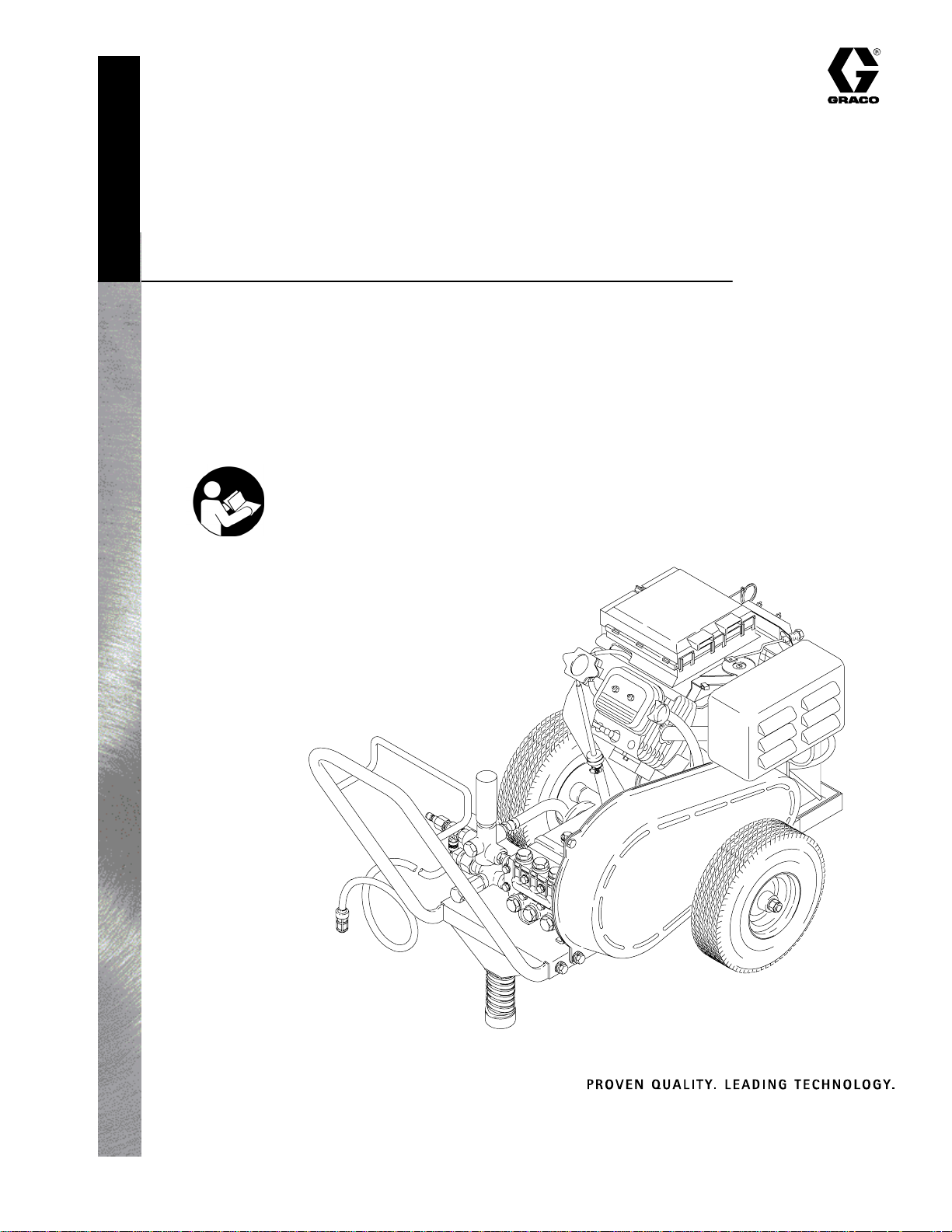
Hydra–Cleanr 4043, 16 HP Engine
Hydra–Cleanr 4043
Pressure Washer
P/N 800707, Series B
4000 psi (27.6 MPa, 276 bar) Operating Pressure
4300 psi (29.6 MPa, 296 bar) maximum Working Pressure
Important Safety Instructions
Read all warnings and instructions in this manual.
Save these instructions.
See page 2 for Table of Contents.
308532M
06811
GRACO INC.ąP.O. BOX 1441ąMINNEAPOLIS, MNą55440-1441
Copyright 2002, Graco Inc. is registered to I.S. EN ISO 9001
Table of Contents
Warning Symbol
Warnings 2. . . . . . . . . . . . . . . . . . . . . . . . . . . . . . . . . . . . . .
Component Identification and Function 4. . . . . . . . . . . .
Setup 5. . . . . . . . . . . . . . . . . . . . . . . . . . . . . . . . . . . . . . . . .
Operation 6. . . . . . . . . . . . . . . . . . . . . . . . . . . . . . . . . . . . .
Troubleshooting 10. . . . . . . . . . . . . . . . . . . . . . . . . . . . . . .
Pump Service 11. . . . . . . . . . . . . . . . . . . . . . . . . . . . . . . .
Parts List 14. . . . . . . . . . . . . . . . . . . . . . . . . . . . . . . . . . . . .
Accessories 20. . . . . . . . . . . . . . . . . . . . . . . . . . . . . . . . . .
Technical Data 21. . . . . . . . . . . . . . . . . . . . . . . . . . . . . . . .
Warranty 22. . . . . . . . . . . . . . . . . . . . . . . . . . . . . . . . . . . . .
Graco Phone Number 22. . . . . . . . . . . . . . . . . . . . . . . . . .
WARNING
INJECTION HAZARD
Spray from gun, leaks or ruptured components can inject fluid into your body and cause serious injury.
Fluid splashed in eyes or on skin can also cause serious injury.
D Fluid injected into skin may look like just a cut, but it is a serious injury. Get immediate surgical
treatment.
D Do not point gun at anyone or at any part of body.
D Do not stop or deflect leaks with hand, body, glove or rag.
WARNING
This symbol alerts you to the possibility of serious
injury or death if you do not follow instructions.
Caution Symbol
CAUTION
This symbol alerts you to the possibility of damage to
or destruction of equipment if you do not follow
instructions.
D Do not put hand or fingers over spray tip.
D Tighten fluid connections before starting equipment.
D Engage gun trigger safety whenever spraying is stopped.
D Follow Pressure Relief Procedure on page 6 if spray tip clogs and before cleaning, checking or
servicing equipment.
D Repair or replace worn or damaged parts immediately.
D Check hoses, tubes, and coupling daily. Do not repair high pressure couplings: replace entire hose.
Fluid hoses must have spring guards on both ends to prevent kinks and rupture.
3085322

WARNING
HAZARDOUS FLUIDS
Improper handling of hazardous fluids can cause serious injury, even death, due to splashing in eyes,
ingestion or bodily contamination.
D Know specific hazards of fluid being used.
D Store hazardous fluids in approved containers. Dispose of hazardous fluids per local, state and
national guidelines.
D Wear protective eyewear, gloves, clothing, and respirator as recommended by fluid manufacturer.
FUEL HAZARD
The fuel used in this unit is combustible and when spilled on a hot surface can ignite and cause a fire.
D Do not fill fuel tank while engine is running or hot.
EXHAUST HAZARD
The exhaust contains poisonous carbon monoxide which is colorless and odorless.
D Do not operate this equipment in a closed building.
EQUIPMENT MISUSE HAZARD
Misuse of pressure washer or accessories may cause them to rupture and result in fluid injection,
splashing in eyes or on skin, or other serious injury.
D Do not alter or modify this equipment. Use only genuine Graco parts and accessories.
D Do not exceed maximum working pressure of any component or accessory in system.
D Do not use any chemicals that are incompatible with wetted parts as stated in Technical Data.
D Do not alter throttle setting.
308532 3
Component Identification and Function
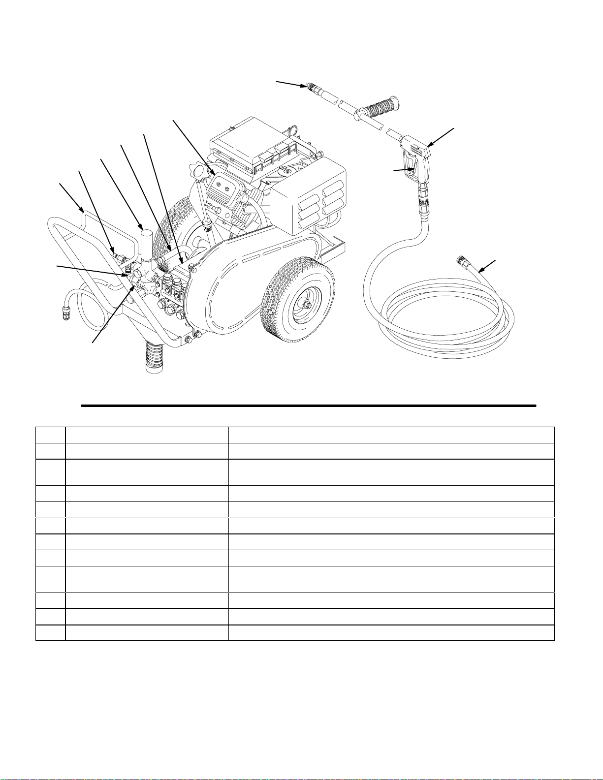
Typical Installation – Pressure Washer
A
B
L
K
E
M
D
G
F
H
J
C
Fig. 1
Engine 16 horsepower, operates pump assembly
A
B Pump Assembly Pressurizes fluid to be sprayed through spray gun
C Filter Screens out debris and other material between supply connection and
D Water Supply Connection Water supply connection for pump
E High Pressure Hose Connection Hose and spray gun connection
F Spray Gun High pressure spray gun with gun safety latch
G Spray Tip Variety of spray tips depending on job needs
H Spray Gun Safety Latch Prevents accidental triggering of spray gun
J Spray Hose 50 ft (15 m), 3/8 in. ID, grounded hose with hose bend restrictors on
K Unloader Relieves fluid pressure when open
L Unloader Bypass Hose Provides bypass loop when unloader valve is open
M Hose Rack Provides storage for spray hose
06811
06812
pump.
both ends
3085324
Setup
Check for Shipping Damage
Check the unit for any damage that may have occurred
in shipping. Notify the carrier immediately if there is
any damage.
Set Up
Charge the battery. Be sure the battery connections
are correct and secure. Connect the fuel line to the
engine using the quick coupler provided. Squeeze the
priming bulb 3 to 5 times. If you are using a downstream chemical injector, install it between the pump
unloader and the high pressure hose, using the quick
couplers provided.
Connect the high pressure hose between the pump
outlet and the gun inlet. Both of these connections are
made with quick couplers.
CAUTION
Up to 100 ft (30 m) of high pressure hose may
be used. Longer hoses may affect sprayer performance, and chemical injector performance, if used.
Install the appropriate spray tip on the wand. See
Installing and Changing Spray Tips. If you are using a
sandblaster kit, see its separate manual for installation
instructions.
Connect to Water Supply
CAUTION
Before attaching to the water supply, check your
local plumbing code regarding cross–connection to
the water supply. Use a backflow preventer if
required by local code.
Do not exceed 160_F (70_C) inlet water temperature.
Connect a hose with at least a 3/4 inch (19 mm) ID
from the water supply to the unit’s 3/4 inch garden
hose inlet. The supply hose should not be more than
50 ft (15 m) long.
NOTE: The water source at the unit must have a
minimum flow rate equal to that of the unit (see
Technical Data, inside back cover).
308532 5
Operation
Pressure Relief Procedure
WARNING
INJECTION HAZARD
System pressure must be manually
relieved to prevent system from starting
or spraying accidentally. Fluid under high
pressure can be injected through skin and cause
serious injury. To reduce risk of injury from injection, splashing fluid, or moving parts, follow Pres-
sure Relief Procedure whenever you:
D are instructed to relieve pressure,
D stop spraying for more than 10 minutes,
D check or service system equipment,
D install or clean spray nozzle.
1. Engage trigger safety latch.
2. Turn sprayer off.
3. Remove ignition cable from spark plug.
4. Remove siphon tube from water supply.
NOTE: This pressure washer is equipped with a
low–oil sensor that shuts the engine off if the oil
level falls below a certain level. If the unit stops
unexpectedly, check both the oil and the fuel
levels. Check the oil level each time the unit is
refueled.
2. Check fuel level.
WARNING
FIRE HAZARD
Do not refuel a hot engine. Refueling a
hot engine could cause a fire. Use only
fresh, clean regular or unleaded gaso-
line. Close fuel shutoff valve during refueling.
3. Turn on the water supply.
CAUTION
Never run unit dry. Costly damage to pump will
result. Always be sure water supply is sufficient
before operating.
4. Trigger the gun until water sprays from the tip
indicating that the air is purged from the system.
5. Open the fuel shutoff valve. Be sure the spark plug
ignition cables are pushed firmly onto the spark
plugs. Put the ignition shutoff switch in the “on”
position and the throttle in the “run” position.
5. Disengage trigger safety latch and trigger gun to
relieve pressure. Engage trigger safety latch.
6. If spray tip or hose is completely clogged, or
pressure has not been fully relieved after following
steps above: Disengage trigger safety latch and
trigger gun to relieve pressure. Wrap rag around
hose end coupling and VERY SLOWLY loosen
coupling to relieve pressure gradually, then loosen
completely. Now clear tip or hose.
Startup
1. Check oil levels.
D Engine: Add SAE 30 or 10W–30 weight deter-
gent oil as necessary.
D Pump: Add SAE 20 or 30 weight non–deterg-
ent oil.
6. Start the engine.
NOTE: For easier starting, have one person start the
pressure washer while another person triggers
the spray gun.
If the engine is cold, completely close the engine
choke. Press the start button. In cool weather, the
choke may have to be kept closed for 10 to 30
seconds before opening it to keep the engine
running. Otherwise, open the choke as soon as the
engine starts.
If the engine is warm, leave the choke open or
partially closed. Start the engine as described in the
preceding paragraph. When the engine starts, be
sure to open the choke completely.
7. ALWAYS engage the gun’s trigger safety latch
whenever you stop spraying, even for a moment,
to reduce the risk of fluid injection or splashing in
the eyes or on the skin if the gun is bumped or
triggered accidentally.
8. ALWAYS observe the following CAUTIONS to
avoid costly damage to the pressure washer.
3085326
Operation
CAUTION
Pressure washer is equipped with a thermal relief
valve. If pressure washer is operated without
spraying for an extended period (approximately 10
minutes) the valve will expel hot water.
Do not operate pressure washer with inlet water
screen removed. Keep screen clean. Screen keeps
abrasive sediment out of pump, Abrasive sediment
can clog pump or damage cylinders.
Do not pump caustic materials; such materials may
corrode pump components.
9. See the chemical injector or sandblaster kit manual for detailed cleaning information if these accessories are used.
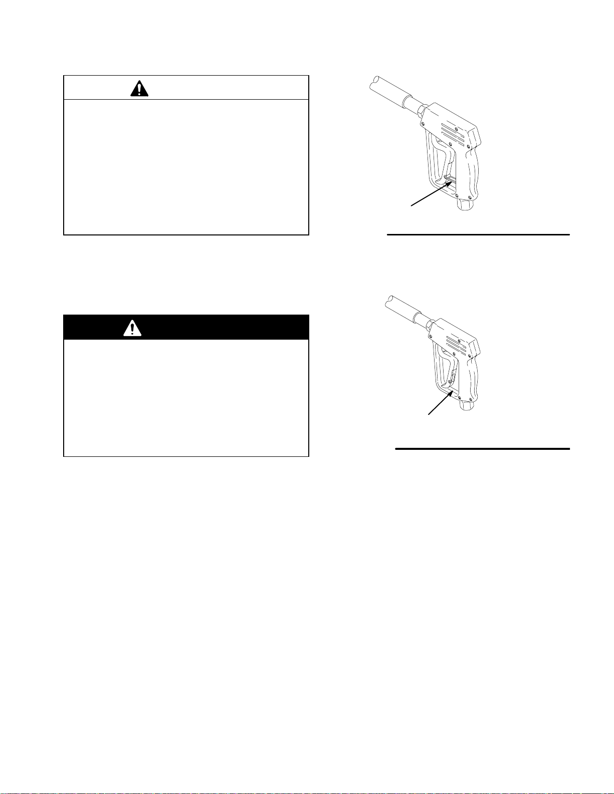
Trigger Safety Latch
WARNING
04612
TRIGGER SAFETY LATCH SHOWN ENGAGED
Figure 2a
To reduce risk of serious bodily injury, including
fluid injection, splashing in eyes or on skin, always
engage trigger safety latch when spraying is
stopped, even for a moment. In engaged position,
trigger safety latch prevents gun from being triggered accidentally by hand or if dropped or
bumped. Be sure to push down latch fully to engage it. If latch not fully engaged, gun can accidentally trigger. See Figures 2a and 2b.
TRIGGER SAFETY LATCH SHOWN
Figure 2b
DISENGAGED
04612
308532 7
 Loading...