

Page 1

Embedded Computing Platform
1
HVP300
Embedded Computing Platform
User Manual
Rev 1.1 Date: January 24th, 2017
Page 2

Embedded Computing Platform
2
Revision
Date
Description
0.1
August 3, 2016
Preliminary
1.0
August 22, 2016
Official release
1.1
January 24, 2017
Added LTE module installation
Modified power input voltage
Modified operating temperature
Added PoE configuraiton description
Added warning statement in the installation
precaution
Added wall mounting section
Revision History
This document contains proprietary information of Lanner Electronics Inc. –and is not to be
disclosed or used except in accordance with applicable agreements.
Copyright © 2017. All Rights Reserved.
Copyright© 2017 Lanner Electronics Inc. All rights reserved. The information in this document is
proprietary and confidential to Lanner Electronics Inc. No part of this document may be
reproduced in any form or by any means or used to make any derivative work (such as
translation, transformation, or adaptation) without the express written consent of Lanner
Electronics Inc. Lanner Electronics Inc. reserves the right to revise this document and to make
changes in content from time to time without obligation on the part of Lanner Electronics Inc. to
provide notification of such revision or change.
The information in this document is furnished for informational use only, is subject to change
without notice, and should not be construed as a commitment by Lanner Electronics Inc. Lanner
Electronics Inc. assumes no responsibility or liability for any errors or inaccuracies that may
appear in this document or any software that may be provided in association with this document.
Page 3

Embedded Computing Platform
3
Resource
Website
Lanner
www.lannerinc.com
Product Resources
www.lannerinc.com/support/download-center
RMA
http://eRMA.lannerinc.com
Online Resources
The listed websites are links to the on-line product information and technical support.
Acknowledgement
Intel®, Pentium and Celeron are registered trademarks of Intel® Corp.
Microsoft Windows and MS-DOS are registered trademarks of Microsoft Corp.
All other product names or trademarks are properties of their respective owners.
Compliances and Certification
CE Certification
This product has passed the CE test for environmental specifications. Test conditions for passing included
the equipment being operated within an industrial enclosure. In order to protect the product from being
damaged by ESD (Electrostatic Discharge) and EMI leakage, we strongly recommend the use of
CE-compliant industrial enclosure products.
FCC Class A Certification
This equipment has been tested and found to comply with the limits for a Class A digital device, pursuant
to Part 15 of the FCC Rules. These limits are designed to provide reasonable protection against harmful
interference when the equipment is operated in a commercial environment. This equipment generates,
uses and can radiate radio frequency energy and, if not installed and used in accordance with the
instruction manual, may cause harmful interference to radio communications. Operation of this
equipment in a residential area is likely to cause harmful interference in which case the user will be
required to correct the interference at his own expense.
EMC Notice
This equipment has been tested and found to comply with the limits for a Class A digital device, pursuant
to Part 15 of the FCC Rules. These limits are designed to provide reasonable protection against harmful
interference when the equipment is operated in a commercial environment. This equipment generates,
uses, and can radiate radio frequency energy and, if not installed and used in accordance with the
instruction manual, may cause harmful interference to radio communications. Operation of this
equipment in a residential area is likely to cause harmful interference in which case users will be required
Page 4

Embedded Computing Platform
4
to correct the interference at their own expense.
Safety Guidelines
Follow these guidelines to ensure general safety:
Keep the chassis area clear and dust-free before, during and after installation.
Do not wear loose clothing or jewelry that could get caught in the chassis. Fasten your tie or scarf and
roll up your sleeves.
Wear safety glasses/goggles if you are working under any conditions that might be hazardous to your
eyes.
Do not perform any action that creates a potential hazard to people or makes the equipment unsafe.
Disconnect all power by turning off the power and unplugging the power cord before installing or
removing a chassis or working near power supplies
Do not work alone if potentially hazardous conditions exist.
Never assume that power is disconnected from a circuit; always check the circuit.
LITHIUM BATTERY CAUTION:
Risk of explosion could occur if battery is replaced by an incorrect type. Please dispose of used batteries
according to the recycling instructions of your country.
Operating Safety
Electrical equipment generates heat. Ambient air temperature may not be adequate to cool
equipment to acceptable operating temperatures without adequate circulation. Be sure that the
room in which you choose to operate your system has adequate air circulation.
Ensure that the chassis cover is secure. The chassis design allows cooling air to circulate effectively.
An open chassis permits air leaks, which may interrupt and redirect the flow of cooling air from
internal components.
Electrostatic discharge (ESD) can damage equipment and impair electrical circuitry. ESD damage occurs
when electronic components are improperly handled and can result in complete or intermittent failures.
Be sure to follow ESD-prevention procedures when removing and replacing components to avoid these
problems.
Wear an ESD-preventive wrist strap, ensuring that it makes good skin contact. If no wrist strap is
available, ground yourself by touching the metal part of the chassis.
Periodically check the resistance value of the antistatic strap, which should be between 1 and 10
megohms (Mohms).
Installation only by a trained electrician or only by an electrically trained person who knows all the
applied or related installation and device specifications..
Do not carry the handle of power supplies when moving to other place.
Page 5

Embedded Computing Platform
5
The machine can only be used in a fixed location such as labs or computer facilities.
Mounting Installation Environment Precaution
1. Elevated Operating Ambient - If installed in a closed or multi-unit rack assembly, the operating ambient
temperature of the rack environment may be greater than room ambient. Therefore, consideration
should be given to installing the equipment in an environment compatible with the maximum ambient
temperature (Tma) specified by the manufacturer.
2. Reduced Air Flow - Installation of the equipment in a rack should be such that the amount of air flow
required for safe operation of the equipment is not compromised.
3. Mechanical Loading - Mounting of the equipment in the rack should be such that a hazardous condition
is not achieved due to uneven mechanical loading.
4. Circuit Overloading - Consideration should be given to the connection of the equipment to the supply
circuit and the effect that overloading of the circuits might have on over-current protection and supply
wiring. Appropriate consideration of equipment nameplate ratings should be used when addressing this
concern.
5. Reliable Earthing - Reliable earthing of rack-mounted equipment should be maintained. Particular
attention should be given to supply connections other than direct connections to the branch circuit (e.g.
use of power strips).”
6. Warning: the unit must be installed indoors. The unit, AC power adapter, and its cables are not
designed for outdoor use.
Consignes de sécurité
Suivez ces consignes pour assurer la securite generale :
Laissez la zone du chassis propre et sans poussiere pendant et apres l’installation.
Ne portez pas de vetements amples ou de bijoux qui pourraient etre pris dans le chassis. Attachez
votre cravate ou echarpe et remontez vos manches.
Portez des lunettes de securite pour proteger vosmyeux.
N’effectuez aucune action qui pourrait creer un dangermpour d’autres ou rendre l’equipement
dangereux.
Coupez completement l’alimentation en eteignant l’alimentation et en debranchant le cordon
d’alimentation avant d’installer ou de retirer un chassis ou de travailler a proximite de sources
d’alimentation.
Ne travaillez pas seul si des conditions dangereuses sont presentes.
Ne considerez jamais que l’alimentation est coupee d’un circuit, verifiez toujours le circuit. Cet
appareil genere, utilise et emet une energie radiofrequence et, s’il n’est pas installe et utilise
conformement aux instructions des fournisseurs de composants sans fil, il risque de provoquer des
Page 6

Embedded Computing Platform
6
interferences dans les communications radio.
Avertissement concernant la pile au lithium
Risque d’explosion si la pile est remplacee par une autre d’un mauvais type.
Jetez les piles usagees conformement aux instructions.
L’installation doit etre effectuee par un electricien forme ou une personne formee a l’electricite
connaissant toutes les specifications d’installation et d’appareil du produit.
Ne transportez pas l’unite en la tenant par le cable d’alimentation lorsque vous deplacez l’appareil.
La machine ne peut etre utilisee qu’a un lieu fixe comme en laboratoire, salle d’ordinateurs ou salle
de classe.
Sécurité de fonctionnement
L’equipement electrique genere de la chaleur. La temperature ambiante peut ne pas etre adequate
pour refroidir l’equipement a une temperature de fonctionnement acceptable sans circulation
adaptee. Verifiez que votre site propose une circulation d’air adequate.
Verifiez que le couvercle du chassis est bien fixe. La conception du chassis permet a l’air de
refroidissement de bien circuler. Un chassis ouvert laisse l’air s’echapper, ce qui peut interrompre et
rediriger le flux d’air frais destine aux composants internes.
Les decharges electrostatiques (ESD) peuvent endommager l’equipement et gener les circuits
electriques. Des degats d’ESD surviennent lorsque des composants electroniques sont mal manipules
et peuvent causer des pannes totales ou intermittentes. Suivez les procedures de prevention d’ESD
lors du retrait et du remplacement de composants.
- Portez un bracelet anti-ESD et veillez a ce qu’il soit bien au contact de la peau. Si aucun bracelet n’est
disponible, reliez votre corps a la terre en touchant la partie metallique du chassis. Verifiez regulierement
la valeur de resistance du bracelet antistatique, qui doit etre comprise entre 1 et 10 megohms (Mohms).
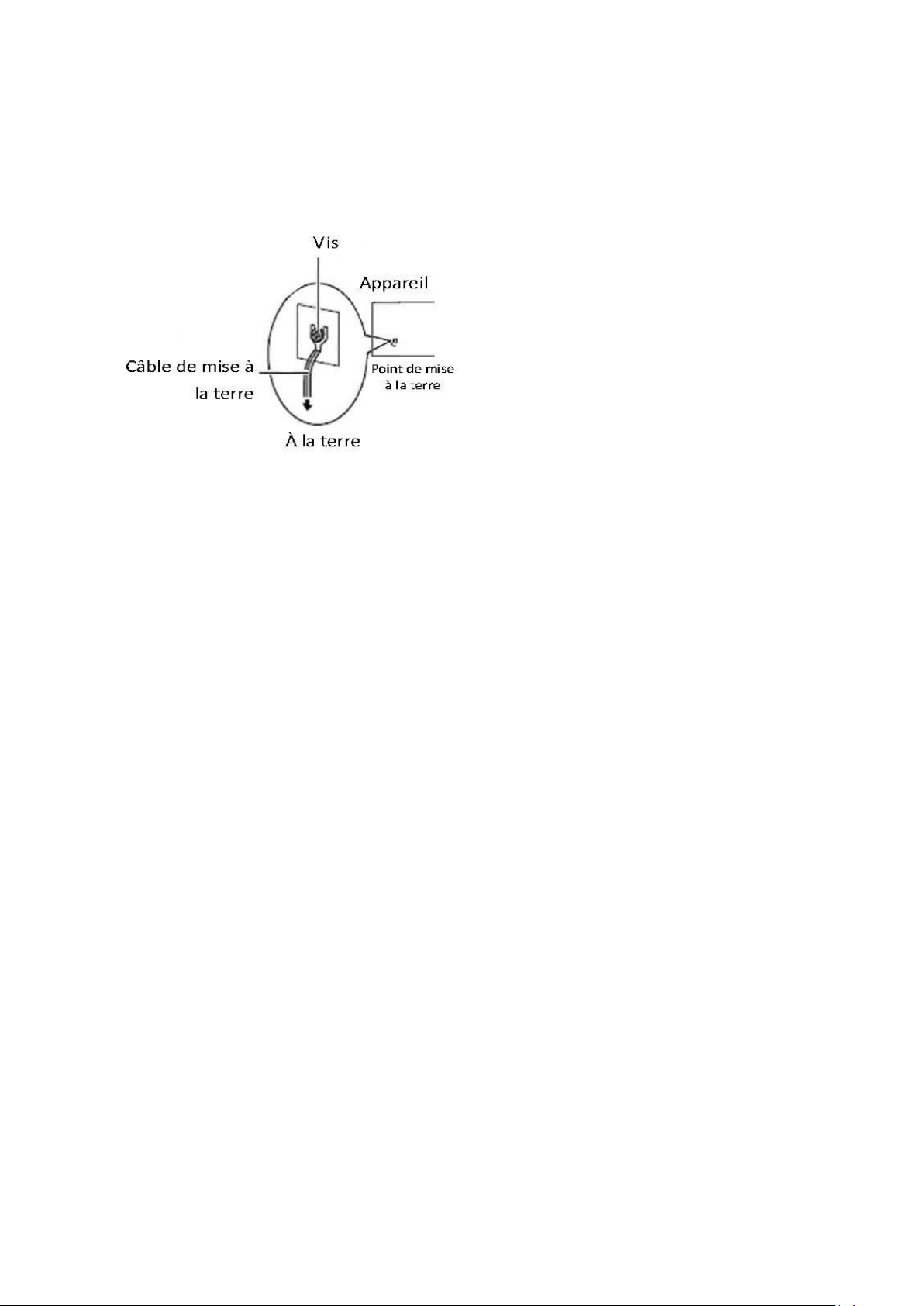
Consignes de sécurité électrique
Avant d’allumer l’appareil, reliez le cable de mise a la terre de l’equipement a la terre.
Une bonne mise a la terre (connexion a la terre) est tres importante pour proteger l equipement
contre les effets nefastes du bruit externe et reduire les risques d’electrocution en cas de foudre.
Pour desinstaller l’equipement, debranchez le cable de mise a la terre apres avoir eteint l’appareil.
Un cable de mise a la terre est requis et la zone reliant les sections du conducteur doit faire plus de 4
mm2 ou 10 AWG.
Procédure de mise à la terre pour source d’alimentation CC
• Desserrez la vis du terminal de mise a la terre.
• Branchez le cable de mise a la terre a la terre.
• L’appareil de protection pour la source d’alimentation
Page 7
Embedded Computing Platform
7
CC doit fournir 30 A de courant. Cet appareil de protection doit etre branche a la source
d’alimentation avant l’alimentation CC.
Page 8

Embedded Computing Platform
8
Table of Contents
Chapter 1: Introduction ...................................................................................................... 9
Specifications .............................................................................................................. 9
Ordering Information ................................................................................................ 10
Chapter 2: System Overview ..............................................................................................11
Mechanical Drawing ...................................................................................................11
Front I/Os .................................................................................................................. 12
Rear I/Os .................................................................................................................... 13
Chapter 3: Board Layout ................................................................................................... 14
Jumper Settings & Connector Pinout (Motherboard) .............................................. 14
Chapter 4: Hardware Setup............................................................................................... 22
Installing SO-DIMM Memory .................................................................................... 23
Installing mSATA and Mini-PCIe Module ................................................................... 24
Installing LTE Wireless Network Module .................................................................. 25
Installing Disk Drives ............................................................................................... 26
Wall Mounting .......................................................................................................... 28
Appendix 1: Watchdog Timer ........................................................................................... 29
Page 9

Embedded Computing Platform
9
Processor
Onboard Intel Skylake-U SoC processor options:
Intel® Core™ i7-6600U (15W)
Memory
2x DDR3L 1333/1600MHz SO-DIMM sockets
supporting up to 16GB
BIOS
AMI SPI Flash BIOS
Serial
4 x D-Sub9 COM ports with RS-232/422/485 signals
USB
4 x USB 3.0 Type-A ports in dual double-stacked form
2 x USB 2.0 Type-A ports in double-stacked form
Display
Intel Integrated HD Graphic Engine
2 x HDMI ports
Storage
1x mSATA mini socket
1 x dual 2.5” SATA HDD/SSD drive bay
Chapter 1: Introduction
Thank you for choosing HVP300. This industrial embedded system is empowered by Intel® Core™
i7-6600U SoC processors (codenamed Skylake-U). The I/O features include four RS-232/422/485 serial
ports, four USB 3.0, two USB 2.0 ports and two HDMI ports. For networking communications, the HVP300
comes with two 10/100/1000 Mbps Ethernet ports and four PoE ports for even greater flexibility.
Product Features:
Intel® Core™ i7-6600U SoC
2 x DDR3L 1333/1600MHz SO-DIMM sockets supporting up to 16GB
Intel® HD Graphics
2x HDMI display output ports
6x RJ45 (HVP300) or 2x RJ45 & 4x PoE (HVP300P)
4x USB 3.0 and 2x USB 2.0
2x 2.5” HDD/SSD with RAID 0/1
4x Serial Ports with RS-232/422/485 signals
0°C ~ +40°C Wide Operating Temperature Range
2 x mini-PCIe sockets (1 x full-size and 1 x half-size) with PCIe and USB signals (the full-size socket is
compatible with LTE module)
1 x mSATA socket for internal storage
Please refer to the following table for detailed specifications
Specifications
Page 10

Embedded Computing Platform
10
Expansion
1x standard mini-PCI express socket (full size) with
SIM card reader, compatible with LTE module
1x half-sized mini-PCI express socket
1x mSATA mini socket
Antenna
2 x SMA antenna holes (sealed by default)
Networking
Ethernet Controller
1x Intel i219
5x Intel i210
Ethernet Ports
6 x RJ-45 10/100/1000Mbps ports
PoE
4 x RJ-45 LAN ports with PoE function
LEDs
2 x LED for Power-on status(Green) and Storage
access status(Yellow)
2 x LED for 3G & WiFi communication access
Physical
Characteristics
Dimensions
164.5 x 143.0 x 30.0, unit: mm
Mounting
Wall mount, VESA mount
Power
Input
1x 2pin terminal block, support DC +24V input
Adapter
24V/5A, 120W with PoE
Reliability Tool
Automatic Reboot
Setting
Lanner Watchdog Timer 1~255 level per second or
minute
Environment
Operating
Temperature
0°C - 40°C
Non-operating
Temperature
-20 - 70℃
Humidity
5 to 95% (non-condensing)
Green
RoHS
Operating System Supported
WES 7 E/P, Win 7 Pro FES, WE 8.1 Industry Pro, Win10
IOT
Standards &
Regulations
EMC
CE, FCC Class A
HVP300
Embedded industrial PC with Intel i7-6600U w/ 4-ports PoE
Ordering Information
Page 11

Embedded Computing Platform
11
Unit: mm
Chapter 2: System Overview
Mechanical Drawing
Page 12

12
F1 LAN
6 x 10/100/1000 mbps RJ-45 LAN ports
LAN3-LAN6 are PoE ports
F2 USB 3.0
4 x USB3.0 Type-A ports in dual double-stacked form
F3 LED
2 x LED for Power-on status(Green) and Storage access
status(Yellow)
2 x LED for 3G & WiFi communication access
F4 Reset
1 x Reset button
F5 Antenna
2 x SMA antenna holes (sealed by default)
F1
F2
F3
F4
F5
F5
Front I/Os
Embedded Computing Platform
Page 13

13
R1 Power Input
1 x2-pin terminal block, support DC +24V input
R2 Remote Power On/Off
1x 2pin terminal block for remote power on/off
R3 COM
4 x D-sub COM ports with RS-232/422/485 signals
R4 USB
2 x USB 2.0 Type-A ports in double-stacked form
R5 HDMI
2 x HDMI ports
R1
R2
R3
R4
R5
Rear I/Os
Embedded Computing Platform
Page 14

Embedded Computing Platform
14
Pin No.
Description
Pin No.
Description
1
DATA2+
2
GND
3
DATA2-
4
DATA1+
5
GND
6
DATA1-
7
DATA0+
8
GND
9
DATA0-
10
CLK+
11
GND
12
CLK-
13
N.C
14
N.C
15
DDC CLK
16
DDC DAT
17
GND
18
HDMI_VCC
19
HPD
Pin No.
Description
Pin No.
Description
1
DATA2+
2
GND
3
DATA2-
4
DATA1+
5
GND
6
DATA1-
7
DATA0+
8
GND
9
DATA0-
10
CLK+
11
GND
12
CLK-
13
N.C
14
N.C
15
DDC CLK
16
DDC DAT
17
GND
18
HDMI_VCC
19
HPD
Chapter 3: Board Layout
Jumper Settings & Connector Pinout (Motherboard)
HDMI1: High-Definition Multimedia Interface connector
HDMI2: High-Definition Multimedia Interface connector
Page 15

Embedded Computing Platform
15
Pin No.
Description
1
TXD+
MD0+
2
TXD-
MD0-
3
RX+
MD1+
4
T45
MD2+
5
T45
MD2-
6
RX-
MD1-
7
T78
MD3+
8
T78
MD3-
9
10-/100-/1000+
10
10+/100+/1000-
11
Active LED+
12
Active LED-(yellow)
LAN1-6: LAN Connectors (RJ-45 connectors with LED) at 10/100/1000Mbps for Ethernet
connectivity. LAN3 to LAN6 are PoE ports.
USB1-2: 4 x USB3.0 Type-A Connectors in dual double-stacked form
Page 16

Embedded Computing Platform
16
PIN NO.
DESCRIPTION
1
USB_VCC1
2
-USB
3
+USB
4
GND
0
USB_VCC2
6
-USB
7
+USB
8
GND
Pin No.
Description
Pin No.
Description
1
USB_VCC1
2
USB1_D-
3
USB1_D+
4
GND
5
USB1_RX-
6
USB1_RX+
7
GND
8
USB1_TX-
9
USB1_TX+
10
USB_VCC1
11
USB1_D-
12
USB1_D+
13
GND
14
USB1_RX-
15
USB1_RX+
16
GND
17
USB1_TX-
18
USB1_TX+
USB3
5
8 4 1
USB3: USB2.0 Type-A Connectors in double-stacked form
COM1/COM2: 4 x DB-9 COM ports with RS-232/422/485 signals (COM1-4 on the panel)
Page 17

17
Pin
Signal
Pin
Signal
1
Data Carrier Detect (DCDA#)
6
Data Set Ready (DSRA#)
2
Receive Data (RXDA)
7
Request To Send (RTSA#)
3
Transmit Data (TXDA)
8
Clear To Send (CTSA#)
4
Data Terminal Ready (DTRA#)
9
Ring Indicator (RIA#)
5
GND
Pin
RS-232
RS-422
RS-485
1
DCD
TX-
RTX-
2
RXD
TX+
RTX+
3
TXD
RX+
4 DTR
RX- 5
GND
6
DSR
7
RTS
8
CTS
9
RI
RS-232/422/485
Embedded Computing Platform
Page 18

Embedded Computing Platform
18
Pin
Description
Pin
Description
1
WAKE#
2
+3.3V
3
RSVD
4
GND
5
RSVD
6
+1.5V
7
CLKREQ#
8
UIM_PWR
9
GND
10
UIM_DATA
11
REFCLK-
12
UIM_CLK
13
REFCLK+
14
UIM_RESET
15
GND
16
UIM_VPP
KEY
17
RSVD
18
GND
19
RSVD
20
W_DISABLE#
21
GND
22
PERST#
23
PERn0
24
+3.3V
25
PERp0
26
GND
27
GND
28
+1.5V
29
GND
30
SMB_CLK
31
PETn0
32
SMB_DATA
33
PETp0
34
GND
35
GND
36
USB_D+
37
GND
38
USB_D-
39
+3.3V
40
GND
41
+3.3V
42
LED_WWAN#
43
GND
44
LED_WLAN#
45
RSVD
46
LED_WPAN#
47
RSVD
48
+1.5V
49
RSVD
50
GND
51
RSVD
52
+3.3V
MPCIE1
MPCIE1: mini-PCIe slot with USB signals and SIM card reader (Full Size) for wireless
module
Page 19

Embedded Computing Platform
19
Pin
Description
Pin
Description
1
WAKE#
2
+3.3V
3
RSVD
4
GND
5
RSVD
6
+1.5V
7
CLKREQ#
8
UIM_PWR
9
GND
10
UIM_DATA
11
REFCLK-
12
UIM_CLK
13
REFCLK+
14
UIM_RESET
15
GND
16
UIM_VPP
KEY
17
RSVD
18
GND
19
RSVD
20
W_DISABLE#
21
GND
22
PERST#
23
PERn0
24
+3.3V
25
PERp0
26
GND
27
GND
28
+1.5V
29
GND
30
SMB_CLK
31
PETn0
32
SMB_DATA
33
PETp0
34
GND
35
GND
36
USB_D+
37
GND
38
USB_D-
39
+3.3V
40
GND
41
+3.3V
42
LED_WWAN#
43
GND
44
LED_WLAN#
45
RSVD
46
LED_WPAN#
47
RSVD
48
+1.5V
49
RSVD
50
GND
51
RSVD
52
+3.3V
MPCIE2: half-sized mini-PCIe slot with PCIe and USB signals for wireless modules
Page 20

Embedded Computing Platform
20
Pin
Description
Pin
Description
1
N.C 2 +3.3V
3
N.C 4 GND
5
N.C 6 N.C 7 N.C 8 N.C 9 GND
10
N.C
11
N.C
12
N.C
13
N.C
14
N.C
15
GND
16
N.C KEY
17
N.C
18
GND
19
N.C
20
N.C
21
GND
22
N.C
23
SATA_RXp
24
+3.3V
25
SATA_RXn
26
GND
27
GND
28
N.C
29
GND
30
N.C
31
SATA_TXn
32
N.C
33
SATA_TXp
34
GND
35
GND
36
N.C
37
GND
38
N.C
39
+3.3V
40
GND
41
+3.3V
42
N.C
43
GND
44
N.C
45
N.C
46
N.C
47
N.C
48
N.C
49
N.C
50
GND
51
N.C
52
+3.3V
MSATA1: mSATA mini slot for storage device (half-sized form)
Page 21

Embedded Computing Platform
21
PIN
DESCRIPTION
1
DC_IN (-)
2
DC_IN (24V)
Short Pins
Description
1-2
Normal (Default)
2-3
Clear CMOS
Short Pins
Description
1-2
Normal (Default)
2-3
Flash ME
PIN
DESCRIPTION
PIN
DESCRIPTION
1
SPI_HOLD
2
N.C 3 SPI_CS#
4
SPI_VCC
5
SPI_MO
6
N.C 7 N.C 8 SPI_CLK
9
GND
10
SPI_MI
Clear CMOS
Normal(Def)
CMOS1
1
2
3
CMOS1
1
2
3
1
2
3
2
SPI1
9
10
1
Flash ME
Normal(Def)
ME1
1
2
3
ME1
1
2
3
1
2
3
DCIN1: DC Power input through 2-pin 5.0mm Phoenix connector
JCMOS1: Clear CMOS setting
JME1: flash ME (Manageability Engine)
SPI1: SPIROM pin header for debug purpose
Page 22

Embedded Computing Platform
22
Chapter 4: Hardware Setup
Accessing the Inside of HVP300
To access some components and perform certain service procedures, you must perform the following
procedures first.
WARNING:
To reduce the risk of personal injury, electric shock, or damage to the equipment, please remove all
power sources.
Please wear ESD protected gloves before conducting the following steps.
Do NOT pile items on top of the system to prevent damages due to this improper use. Lanner is not
liable for damages caused by improper use of the product.
1. Power off HVP300 and remove the power cord.
2. Rotate and remove the four rubber pads at the bottom compartment.
2. Lift and open the chassis.
Page 23

Embedded Computing Platform
23
Installing SO-DIMM Memory
The system is designed with two SO-DIMM sockets supporting up to 16GB DDR3L 1333/1600MHz. Please
follow the steps below for proper installations.
1. Locate the SO-DIMM sockets on the motherboard.
2. Select the socket for installing the module. Align the memory module’s key with the SO-DIMM socket’s
key.
3. Insert the SO-DIMM module.
4. Press the module down until it is locked by the two clips at each side.
Page 24

Embedded Computing Platform
24
Mini-PCIe
(full-sized)
Mini-PCIe
(half-sized)
mSATA mini
Installing mSATA and Mini-PCIe Module
The system provides one mSATA mini socket and two mini-PCIe sockets (one full-sized and another
half-sized) for storage and wireless modules. Please follow the steps below for installations.
1. Locate the mSATA and the mini-PCIe sockets.
2. Select the socket for installing the module. Align the mechanical notches between the module and the
socket.
3. Insert the module into the socket.
4. Secure the installed module with two screws.
Page 25

Embedded Computing Platform
25
Installing LTE Wireless Network Module
The mini-PCIe socket of the system is compatible with LTE wireless network module. Please follow the
steps below for installations.
1. Locate the mini-PCIe sockets.
2. Align the mechanical notches between the module and the socket.
3. Insert the LTE wireless network module (Sierra M7354 in this case) into the socket.
4. Secure the installed module with two screws.
Page 26

Embedded Computing Platform
26
Installing Disk Drives
The system supports 1 x dual 2.5” SATA HDD/SSD drive bay as data storage (SSD is
recommended due to heat and vibration concerns). Please follow the steps below for installation.
1. Locate the dual 2.5” SATA HDD/SSD drive bay at the back of the bottom compartment.
2. Place disk drives onto the drive bay and apply two screws on each side of a SATA disk drive.
3. Connect the SATA 7-pin signal cable and the SATA 4-pin power cable to their corresponding
connectors on the motherboard.
Page 27

Embedded Computing Platform
27
4. Plug the standard 7+15 SATA connector to the SSD.
Page 28

Embedded Computing Platform
28
Wall Mounting
The system can be mounted on a flat surfaced wall. Please take the following into considerations
when mounting the system onto the wall.
1. Ensure the wall brackets are properly fixed onto the chassis, as illustrated in the drawings
below.
2. Please pay close attention to the dimensional parameters in the drawings below such as the
distance between each screw hole of a bracket piece. The parameter values serve as important
reference for applying standoffs on the wall.
Page 29

Embedded Computing Platform
29
Processor
Watchdog Timer
Reset
Restart
Clock
Appendix 1: Watchdog Timer
A watchdog timer is a piece of hardware that can be used to automatically detect system anomalies and
reset the processor in case there are any problems. Generally speaking, a watchdog timer is based on a
counter that counts down from an initial value to zero. The software selects the counter’s initial value and
periodically restarts it. Should the counter reach zero before the software restarts it, the software is
presumed to be malfunctioning
and the processor’s reset signal is asserted. Thus, the processor will be restarted as if a human operator
had cycled the power.
To download sample watchdog code, please refer to our official website at www.lannerinc.com.
Page 30

Embedded Computing Platform
30
Federal Communications Commission
This device complies with Part 15 of the FCC Rules. Operation is subject to the following two conditions: (1)
This device may not cause harmful interference, and (2) this device must accept any interference received,
including interference that may cause undesired operation.
This equipment has been tested and found to comply with the limits for a Class A digital device, pursuant
to part 15 of the FCC Rules. These limits are designed to pro-vide reasonable protection against harmful
interference when the equipment is operate din a commercial environment. This equipment generates,
uses, and can radiate radiofrequency energy and, if not installed and used in accordance with the
instruction manual, may cause harmful interference to radio communications. Operation of this
equipment in a residential area is likely to cause harmful interference in which case the user will be
required to correct the interference at his own expense.
FCC Caution: Any changes or modifications not expressly approved by the party responsible for
compliance could void the user's authority to operate this equipment.
This device complies with part 15 of the FCC Rules.
Operation is subject to the following two conditions:
(1) This device may not cause harmful interference, and
(2) this device must accept any interference received, including interference that may cause undesired
operation.
Radiation Exposure Statement:
This equipment complies with FCC radiation exposure limits set forth for an uncontrolled environment.
This equipment should be installed and operated with minimum distance 20cm between the radiator &
your body.
 Loading...