HITACHI HD64570 SCA User Manual

HD64570 SCA

Serial Communications Adaptor

User’s Manual

ADE-602-035B

Rev. 3.0

August 28, 1998

Hitachi Company or Division

Cautions

1.Hitachi neither warrants nor grants licenses of any rights of Hitachi’s or any third party’s patent, copyright, trademark, or other intellectual property rights for information contained in this document. Hitachi bears no responsibility for problems that may arise with third party’s rights, including intellectual property rights, in connection with use of the information contained in this document.

2.Products and product specifications may be subject to change without notice. Confirm that you have received the latest product standards or specifications before final design, purchase or use.

3.Hitachi makes every attempt to ensure that its products are of high quality and reliability. However, contact Hitachi’s sales office before using the product in an application that demands especially high quality and reliability or where its failure or malfunction may directly threaten human life or cause risk of bodily injury, such as aerospace, aeronautics, nuclear power, combustion control, transportation, traffic, safety equipment or medical equipment for life support.

4.Design your application so that the product is used within the ranges guaranteed by Hitachi particularly for maximum rating, operating supply voltage range, heat radiation characteristics, installation conditions and other characteristics. Hitachi bears no responsibility for failure or damage when used beyond the guaranteed ranges. Even within the guaranteed ranges, consider normally foreseeable failure rates or failure modes in semiconductor devices and employ systemic measures such as fail-safes, so that the equipment incorporating Hitachi product does not cause bodily injury, fire or other consequential damage due to operation of the Hitachi product.

5.This product is not designed to be radiation resistant.

6.No one is permitted to reproduce or duplicate, in any form, the whole or part of this document without written approval from Hitachi.

7.Contact Hitachi’s sales office for any questions regarding this document or Hitachi semiconductor products.

Preface

The HD64570 serial communications adaptor (SCA) peripheral chip enables a host microprocessor to perform asynchronous, byte-synchronous, or bit-synchronous serial communication. Its two full-duplex, multiprotocol serial channels support a wide variety of protocols, including frame relay, LAPB, LAPD, bisync, and ™DDCMP. Its built-in direct memory access controller (DMAC) is equipped with a 32-stage FIFO and can execute chainedblock transfers. Due to its DMAC and 16-bit bus interface, the SCA supports serial data transfer rates up to 12 Mbits/s without monopolizing the bus, even in full-duplex communication. Other on-chip features of the SCA, including four types of MPU interfaces, a bus arbiter, timers, and an interrupt controller, provide added functionality in a wide range of applications, such as frame relay exchanges/system multiplexes, private branch exchanges, computer networks, workstations, ISDN terminals, and facsimile.

™DDCMP is a trademark of Digital Equipment Corporation.

Rev. 0, 07/98, page i of 11

Changes in the Revised Edition

The following tables list the main differences between this revision and the previous edition (ADE-602-035A). (2nd edition) The changes are marked with stars (*) in the text.

Changes in the Specifications

Specifications

Modifications


WTR SCA added

A chip with Wide Temperature Range


(−40 to 85°C) has been added to the product


lineup.


Changes in the Text

Page Title Modifications

1, 2, 3 1.2 Features,

Table 3.1 Maximum data transfer rate supply voltage product lineup

A chip with Wide Temperature Range

(−40 to 85°C) has been added to the product lineup.

Rev. 0, 07/98, page ii of 11

How to Use This Manual

This user's manual describes the functions, performance, and usage of the HD64570 serial communications adaptor (SCA) as a general-purpose communications control chip.

This manual consists of eleven chapters and an appendix.

— Section 1 Overview

This section outlines the functions, performance, and internal structure of the SCA.

— Section 2 Pin Arrangements and Functions

This section shows the pin arrangements and lists the functions of each pin.

— Section 3 System Controller

This section describes the operating modes of the chip (reset mode, normal operating mode, system stop mode), the bus arbiter functions, and the bus interface needed for interfacing with a host MPU.

— Section 4 Interrupt Controller

This section describes the SCA's interrupt control logic, on-chip interrupt sources, vector output (fixed and modified vectoring), and acknowledge cycle.

— Section 5 MSCI (Multiprotocol Serial Communication Interface)

This section gives a general description of the asynchronous, byte-synchronous, and bitsynchronous communication protocols supported by the built-in multiprotocol serial communication interfaces (MSCI channels 0 and 1) that implement the main functions of the SCA, and shows the register settings for various communication functions.

— Section 6 DMAC (DMA Controller)

This section explains the singleand chained-block transfer modes supported by the built-in direct memory access controller (DMAC channels 0 to 3). Internal register functions and settings are also described.

— Section 7 Timers

This section explains operating modes and register settings of the built-in timers (channels 0 to 3), which generate internal interrupts.

— Section 8 Wait Controller

This section describes the built-in wait controller, which inserts wait states during memory access to one of three physical address spaces. Details about the associated internal registers and WAIT pin are also provided.

Rev. 0, 07/98, page iii of 11

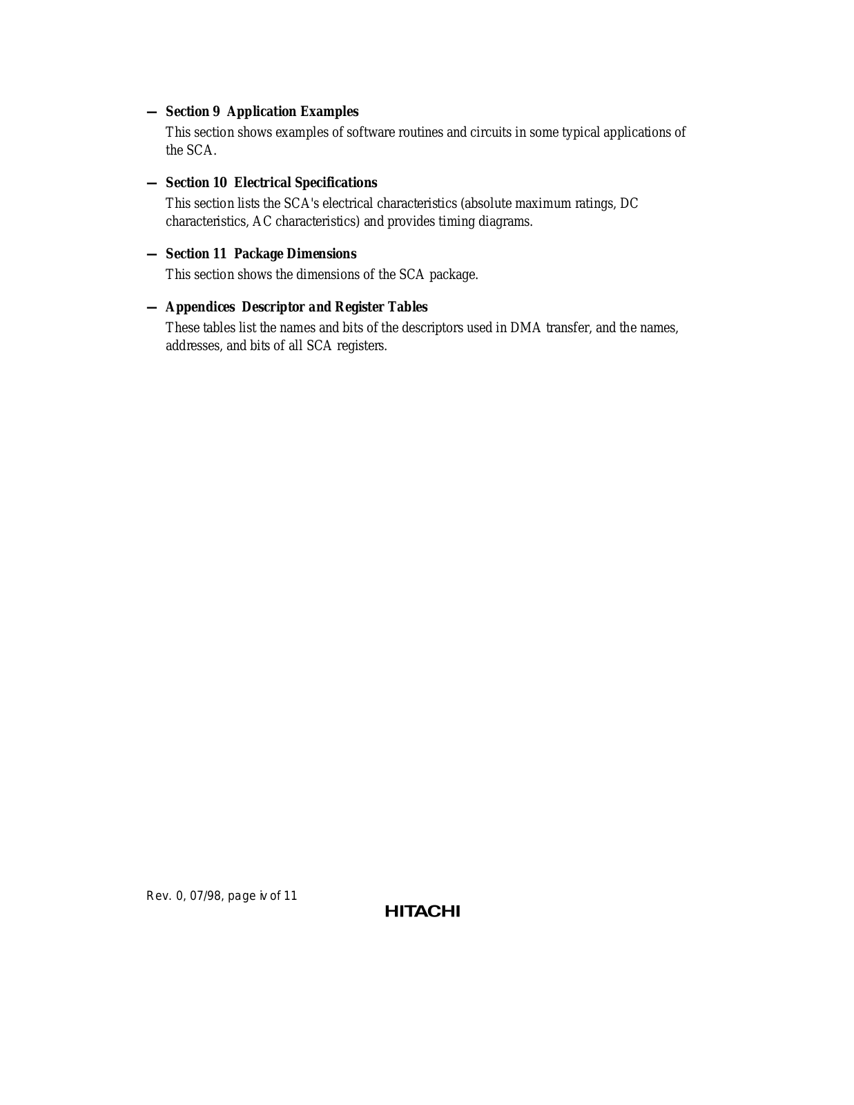
— Section 9 Application Examples

This section shows examples of software routines and circuits in some typical applications of the SCA.

— Section 10 Electrical Specifications

This section lists the SCA's electrical characteristics (absolute maximum ratings, DC characteristics, AC characteristics) and provides timing diagrams.

— Section 11 Package Dimensions

This section shows the dimensions of the SCA package.

— Appendices Descriptor and Register Tables

These tables list the names and bits of the descriptors used in DMA transfer, and the names, addresses, and bits of all SCA registers.

Rev. 0, 07/98, page iv of 11

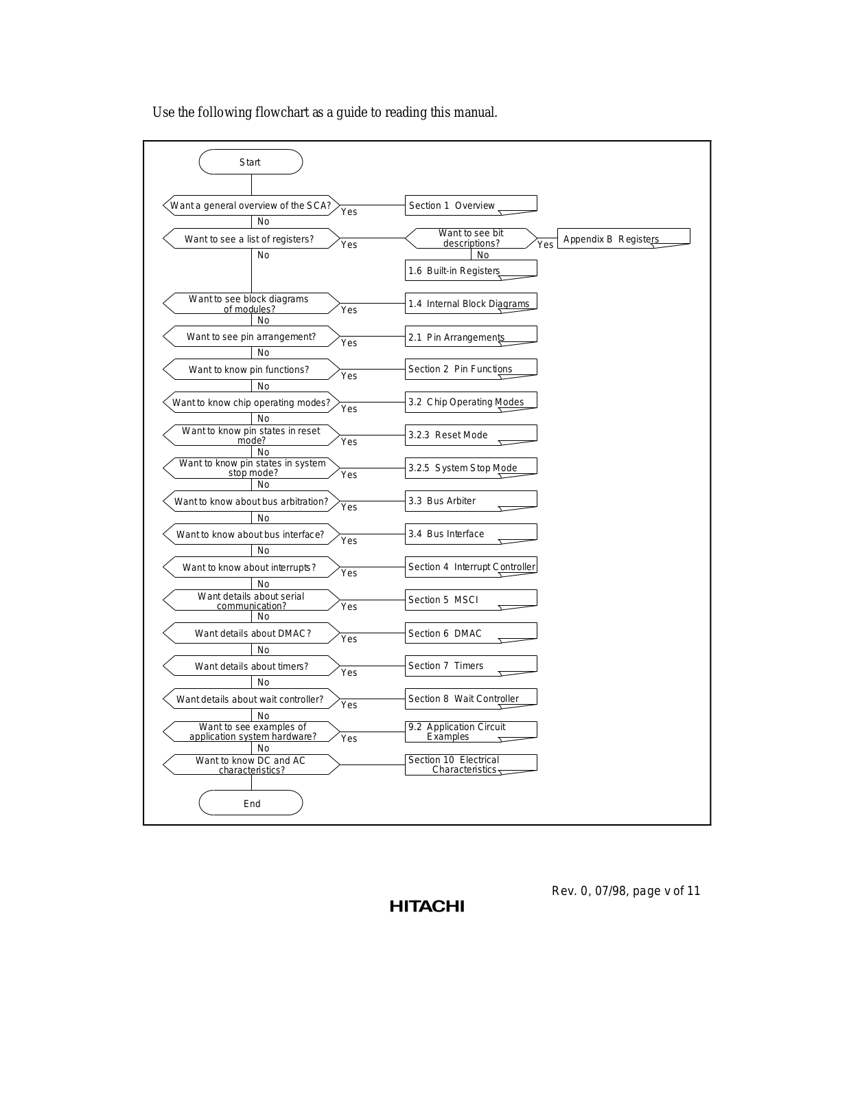
Use the following flowchart as a guide to reading this manual.

Start

Want a general overview of the SCA?

Yes

Section 1 Overview


No


Want to see a list of registers?


Want to see bit


Yes


descriptions?

Yes

No


No


1.6

Built-in Registers


Appendix B Registers

Want to see block diagrams of modules?

No

Want to see pin arrangement?

No

Want to know pin functions?

Yes

1.4

Internal Block Diagrams


Yes

2.1 Pin Arrangements


Yes

Section 2

Pin Functions


No


Want to know chip operating modes?

3.2 Chip Operating Modes

No

Yes


Want to know pin states in reset

3.2.3 Reset Mode

mode?

Yes

No


Want to know pin states in system

3.2.5 System Stop Mode

stop mode?

Yes

No


Want to know about bus arbitration?

3.3 Bus Arbiter


Yes

No

Want to know about bus interface? No

Want to know about interrupts?

No

Want details about serial communication?

No

Want details about DMAC?

Yes

3.4 Bus Interface


Yes

Section 4 Interrupt Controller


Yes

Section 5 MSCI


Yes

Section 6 DMAC


No


Want details about timers?

Yes

Section 7

Timers

No


Want details about wait controller?

Yes

Section 8

Wait Controller


No


Want to see examples of


application system hardware?


Yes


No


Want to know DC and AC


characteristics?


9.2Application Circuit Examples

Section 10 Electrical

Characteristics

End

Rev. 0, 07/98, page v of 11


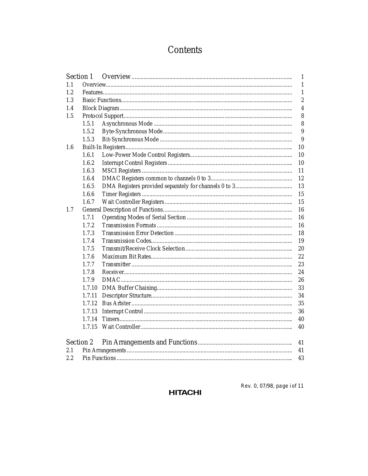
Contents


Section 1

Overview ...........................................................................................................

1

1.1

Overview............................................................................................................................

1

1.2

Features..............................................................................................................................

1

1.3

Basic Functions..................................................................................................................

2

1.4

Block Diagram...................................................................................................................

4

1.5

Protocol Support ................................................................................................................

8


1.5.1

Asynchronous Mode ............................................................................................

8


1.5.2

Byte-Synchronous Mode......................................................................................

9


1.5.3

Bit-Synchronous Mode ........................................................................................

9

1.6

Built-In Registers...............................................................................................................

10


1.6.1

Low-Power Mode Control Registers....................................................................

10


1.6.2

Interrupt Control Registers ...................................................................................

10


1.6.3

MSCI Registers ....................................................................................................

11


1.6.4

DMAC Registers common to channels 0 to 3......................................................

12


1.6.5

DMA Registers provided separately for channels 0 to 3......................................

13


1.6.6

Timer Registers ....................................................................................................

15


1.6.7

Wait Controller Registers .....................................................................................

15

1.7

General Description of Functions......................................................................................

16


1.7.1

Operating Modes of Serial Section ......................................................................

16


1.7.2

Transmission Formats ..........................................................................................

16


1.7.3

Transmission Error Detection ..............................................................................

18


1.7.4

Transmission Codes..............................................................................................

19


1.7.5

Transmit/Receive Clock Selection .......................................................................

20


1.7.6

Maximum Bit Rates..............................................................................................

22


1.7.7

Transmitter ...........................................................................................................

23


1.7.8

Receiver................................................................................................................

24


1.7.9

DMAC ..................................................................................................................

26


1.7.10

DMA Buffer Chaining..........................................................................................

33


1.7.11

Descriptor Structure..............................................................................................

34


1.7.12

Bus Arbiter ...........................................................................................................

35


1.7.13

Interrupt Control ...................................................................................................

36


1.7.14

Timers...................................................................................................................

40


1.7.15

Wait Controller .....................................................................................................

40

Section 2

Pin Arrangements and Functions ...............................................................

41

2.1

Pin Arrangements ..............................................................................................................

41

2.2

Pin Functions .....................................................................................................................

43

Rev. 0, 07/98, page i of 11

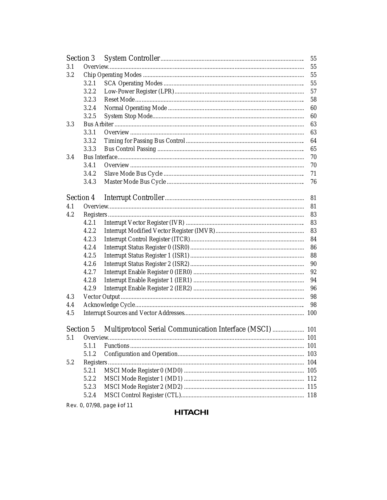
Section 3

System Controller ...........................................................................................

55

3.1

Overview............................................................................................................................

55

3.2

Chip Operating Modes ......................................................................................................

55


3.2.1

SCA Operating Modes .........................................................................................

55


3.2.2

Low-Power Register (LPR)..................................................................................

57


3.2.3

Reset Mode ...........................................................................................................

58


3.2.4

Normal Operating Mode ......................................................................................

60


3.2.5

System Stop Mode................................................................................................

60

3.3

Bus Arbiter ........................................................................................................................

63


3.3.1

Overview ..............................................................................................................

63


3.3.2

Timing for Passing Bus Control ...........................................................................

64


3.3.3

Bus Control Passing .............................................................................................

65

3.4

Bus Interface......................................................................................................................

70


3.4.1

Overview ..............................................................................................................

70


3.4.2

Slave Mode Bus Cycle .........................................................................................

71


3.4.3

Master Mode Bus Cycle .......................................................................................

76

Section 4

Interrupt Controller ........................................................................................

81

4.1

Overview............................................................................................................................

81

4.2

Registers ............................................................................................................................

83


4.2.1

Interrupt Vector Register (IVR) ...........................................................................

83


4.2.2

Interrupt Modified Vector Register (IMVR)........................................................

83


4.2.3

Interrupt Control Register (ITCR)........................................................................

84


4.2.4

Interrupt Status Register 0 (ISR0) ........................................................................

86


4.2.5

Interrupt Status Register 1 (ISR1) ........................................................................

88


4.2.6

Interrupt Status Register 2 (ISR2) ........................................................................

90


4.2.7

Interrupt Enable Register 0 (IER0) ......................................................................

92


4.2.8

Interrupt Enable Register 1 (IER1) ......................................................................

94


4.2.9

Interrupt Enable Register 2 (IER2) ......................................................................

96

4.3

Vector Output ....................................................................................................................

98

4.4

Acknowledge Cycle...........................................................................................................

98

4.5

Interrupt Sources and Vector Addresses............................................................................

100

Section 5

Multiprotocol Serial Communication Interface (MSCI) ....................

101

5.1

Overview............................................................................................................................

101


5.1.1

Functions ..............................................................................................................

101


5.1.2

Configuration and Operation................................................................................

103

5.2

Registers ............................................................................................................................

104


5.2.1

MSCI Mode Register 0 (MD0) ............................................................................

105


5.2.2

MSCI Mode Register 1 (MD1) ............................................................................

112


5.2.3

MSCI Mode Register 2 (MD2) ............................................................................

115


5.2.4

MSCI Control Register (CTL)..............................................................................

118

Rev. 0, 07/98, page ii of 11


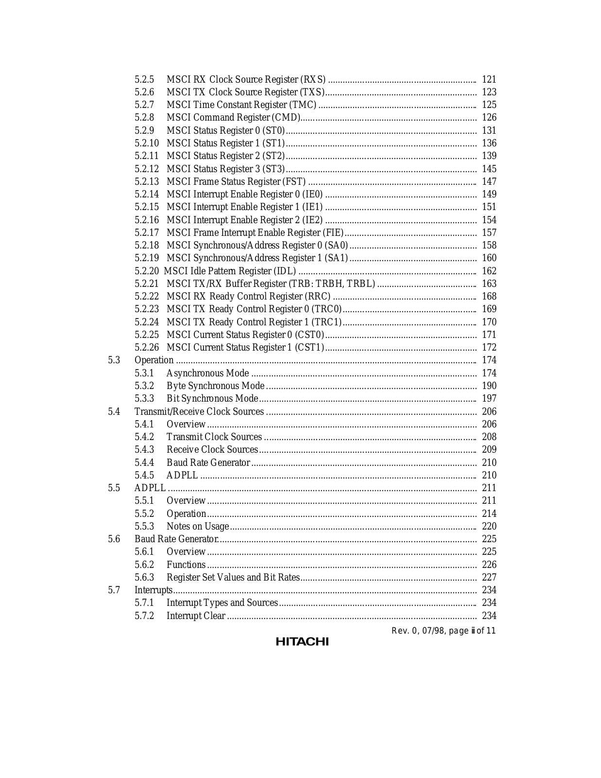
5.2.5

MSCI RX Clock Source Register (RXS) .............................................................

121


5.2.6

MSCI TX Clock Source Register (TXS)..............................................................

123


5.2.7

MSCI Time Constant Register (TMC) .................................................................

125


5.2.8

MSCI Command Register (CMD)........................................................................

126


5.2.9

MSCI Status Register 0 (ST0)..............................................................................

131


5.2.10

MSCI Status Register 1 (ST1)..............................................................................

136


5.2.11

MSCI Status Register 2 (ST2)..............................................................................

139


5.2.12

MSCI Status Register 3 (ST3)..............................................................................

145


5.2.13

MSCI Frame Status Register (FST) .....................................................................

147


5.2.14

MSCI Interrupt Enable Register 0 (IE0) ..............................................................

149


5.2.15

MSCI Interrupt Enable Register 1 (IE1) ..............................................................

151


5.2.16

MSCI Interrupt Enable Register 2 (IE2) ..............................................................

154


5.2.17

MSCI Frame Interrupt Enable Register (FIE)......................................................

157


5.2.18

MSCI Synchronous/Address Register 0 (SA0) ....................................................

158


5.2.19

MSCI Synchronous/Address Register 1 (SA1) ....................................................

160


5.2.20

MSCI Idle Pattern Register (IDL) .........................................................................

162


5.2.21

MSCI TX/RX Buffer Register (TRB: TRBH, TRBL) .........................................

163


5.2.22

MSCI RX Ready Control Register (RRC) ...........................................................

168


5.2.23

MSCI TX Ready Control Register 0 (TRC0).......................................................

169


5.2.24

MSCI TX Ready Control Register 1 (TRC1).......................................................

170


5.2.25

MSCI Current Status Register 0 (CST0)..............................................................

171


5.2.26

MSCI Current Status Register 1 (CST1)..............................................................

172

5.3

Operation ...........................................................................................................................

174


5.3.1

Asynchronous Mode ............................................................................................

174


5.3.2

Byte Synchronous Mode ......................................................................................

190


5.3.3

Bit Synchronous Mode .........................................................................................

197

5.4

Transmit/Receive Clock Sources ......................................................................................

206


5.4.1

Overview ..............................................................................................................

206


5.4.2

Transmit Clock Sources .......................................................................................

208


5.4.3

Receive Clock Sources .........................................................................................

209


5.4.4

Baud Rate Generator ............................................................................................

210


5.4.5

ADPLL .................................................................................................................

210

5.5

ADPLL ..............................................................................................................................

211


5.5.1

Overview ..............................................................................................................

211


5.5.2

Operation ..............................................................................................................

214


5.5.3

Notes on Usage.....................................................................................................

220

5.6

Baud Rate Generator..........................................................................................................

225


5.6.1

Overview ..............................................................................................................

225


5.6.2

Functions ..............................................................................................................

226


5.6.3

Register Set Values and Bit Rates........................................................................

227

5.7

Interrupts............................................................................................................................

234


5.7.1

Interrupt Types and Sources .................................................................................

234


5.7.2

Interrupt Clear ......................................................................................................

234

Rev. 0, 07/98, page iii of 11

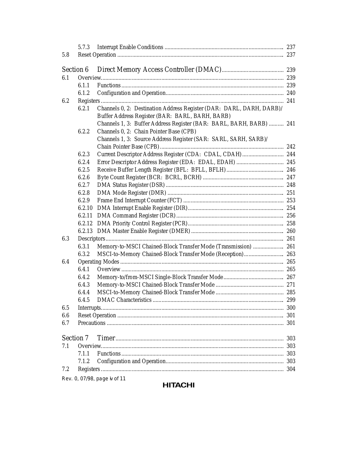
5.7.3 Interrupt Enable Conditions .................................................................................

237

5.8 Reset Operation .................................................................................................................

237

Section 6

Direct Memory Access Controller (DMAC)..........................................

239

6.1

Overview............................................................................................................................

239


6.1.1

Functions ..............................................................................................................

239


6.1.2

Configuration and Operation................................................................................

240

6.2

Registers ............................................................................................................................

241

6.2.1Channels 0, 2: Destination Address Register (DAR: DARL, DARH, DARB)/ Buffer Address Register (BAR: BARL, BARH, BARB)

Channels 1, 3: Buffer Address Register (BAR: BARL, BARH, BARB) ..........

241

6.2.2Channels 0, 2: Chain Pointer Base (CPB)

Channels 1, 3: Source Address Register (SAR: SARL, SARH, SARB)/


Chain Pointer Base (CPB)....................................................................................

242


6.2.3

Current Descriptor Address Register (CDA: CDAL, CDAH) ............................

244


6.2.4

Error Descriptor Address Register (EDA: EDAL, EDAH) ................................

245


6.2.5

Receive Buffer Length Register (BFL: BFLL, BFLH) .......................................

246


6.2.6

Byte Count Register (BCR: BCRL, BCRH) .......................................................

247


6.2.7

DMA Status Register (DSR) ................................................................................

248


6.2.8

DMA Mode Register (DMR) ...............................................................................

251


6.2.9

Frame End Interrupt Counter (FCT) ....................................................................

253


6.2.10

DMA Interrupt Enable Register (DIR).................................................................

254


6.2.11

DMA Command Register (DCR) .........................................................................

256


6.2.12

DMA Priority Control Register (PCR).................................................................

258


6.2.13

DMA Master Enable Register (DMER) ...............................................................

260

6.3

Descriptors .........................................................................................................................

261


6.3.1

Memory-to-MSCI Chained-Block Transfer Mode (Transmission) .....................

261


6.3.2

MSCI-to-Memory Chained-Block Transfer Mode (Reception)...........................

263

6.4

Operating Modes ...............................................................................................................

265


6.4.1

Overview ..............................................................................................................

265


6.4.2

Memory-to/from-MSCI Single-Block Transfer Mode .........................................

267


6.4.3

Memory-to-MSCI Chained-Block Transfer Mode ..............................................

271


6.4.4

MSCI-to-Memory Chained-Block Transfer Mode ..............................................

285


6.4.5

DMAC Characteristics .........................................................................................

299

6.5

Interrupts............................................................................................................................

300

6.6

Reset Operation .................................................................................................................

301

6.7

Precautions ........................................................................................................................

301

Section 7

Timer ..................................................................................................................

303

7.1

Overview............................................................................................................................

303


7.1.1

Functions ..............................................................................................................

303


7.1.2

Configuration and Operation................................................................................

303

7.2

Registers ............................................................................................................................

304

Rev. 0, 07/98, page iv of 11


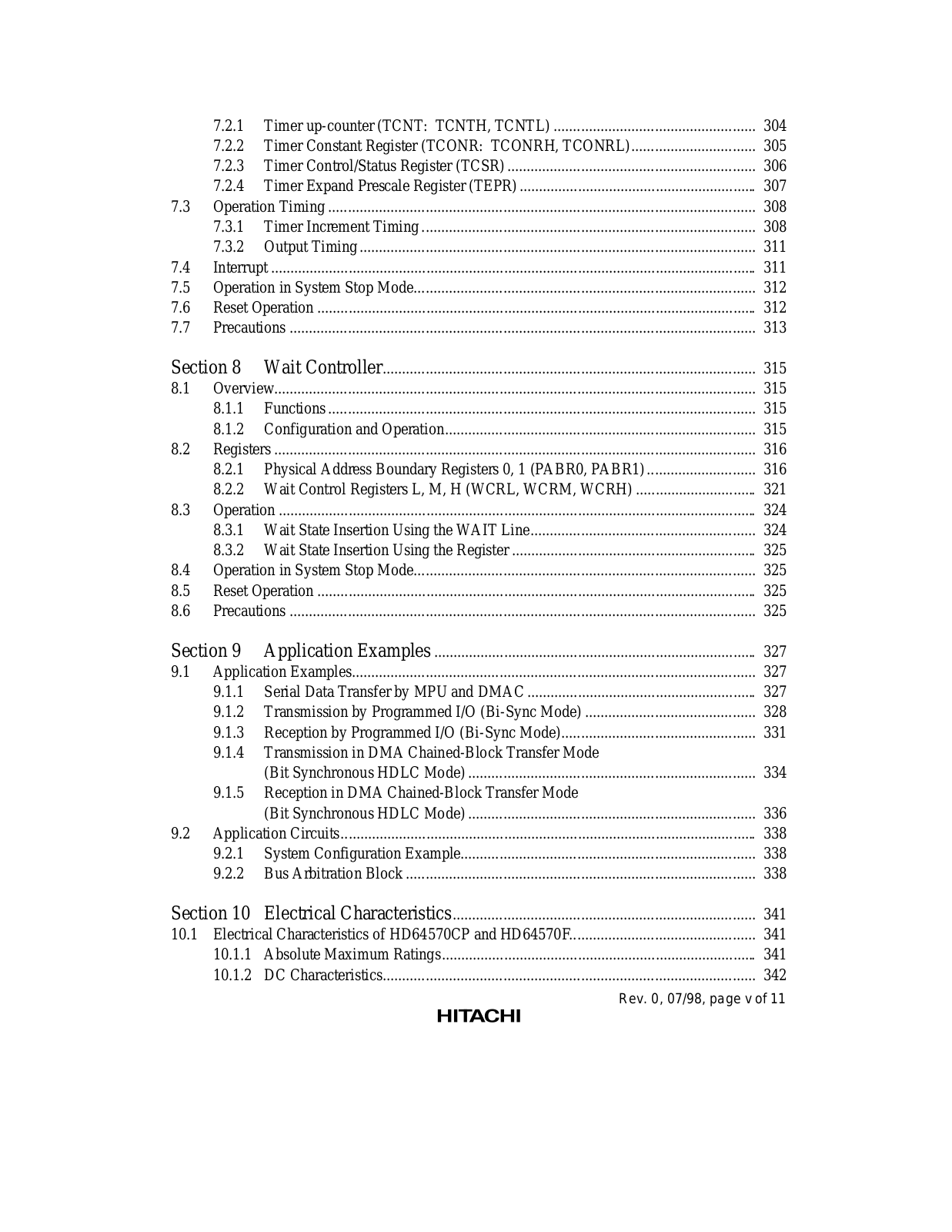
7.2.1

Timer up-counter (TCNT: TCNTH, TCNTL) ....................................................

304


7.2.2

Timer Constant Register (TCONR: TCONRH, TCONRL)................................

305


7.2.3 Timer Control/Status Register (TCSR) ................................................................

306


7.2.4 Timer Expand Prescale Register (TEPR) .............................................................

307

7.3

Operation Timing ..............................................................................................................

308


7.3.1

Timer Increment Timing ......................................................................................

308


7.3.2

Output Timing ......................................................................................................

311

7.4

Interrupt .............................................................................................................................

311

7.5

Operation in System Stop Mode........................................................................................

312

7.6

Reset Operation .................................................................................................................

312

7.7

Precautions ........................................................................................................................

313

Section 8

Wait Controller................................................................................................

315

8.1

Overview............................................................................................................................

315


8.1.1

Functions ..............................................................................................................

315


8.1.2

Configuration and Operation................................................................................

315

8.2

Registers ............................................................................................................................

316


8.2.1

Physical Address Boundary Registers 0, 1 (PABR0, PABR1) ............................

316


8.2.2

Wait Control Registers L, M, H (WCRL, WCRM, WCRH) ...............................

321

8.3

Operation ...........................................................................................................................

324


8.3.1

Wait State Insertion Using the WAIT Line..........................................................

324


8.3.2

Wait State Insertion Using the Register ...............................................................

325

8.4

Operation in System Stop Mode........................................................................................

325

8.5

Reset Operation .................................................................................................................

325

8.6

Precautions ........................................................................................................................

325

Section 9

Application Examples ...................................................................................

327

9.1

Application Examples........................................................................................................

327


9.1.1

Serial Data Transfer by MPU and DMAC ...........................................................

327


9.1.2

Transmission by Programmed I/O (Bi-Sync Mode) ............................................

328


9.1.3

Reception by Programmed I/O (Bi-Sync Mode)..................................................

331

9.1.4Transmission in DMA Chained-Block Transfer Mode

(Bit Synchronous HDLC Mode) ..........................................................................

334

9.1.5Reception in DMA Chained-Block Transfer Mode


(Bit Synchronous HDLC Mode) ..........................................................................

336

9.2 Application Circuits...........................................................................................................

338

9.2.1

System Configuration Example............................................................................

338

9.2.2

Bus Arbitration Block ..........................................................................................

338

Section 10

Electrical Characteristics..............................................................................

341

10.1 Electrical Characteristics of HD64570CP and HD64570F................................................

341

10.1.1

Absolute Maximum Ratings.................................................................................

341

10.1.2

DC Characteristics................................................................................................

342

Rev. 0, 07/98, page v of 11

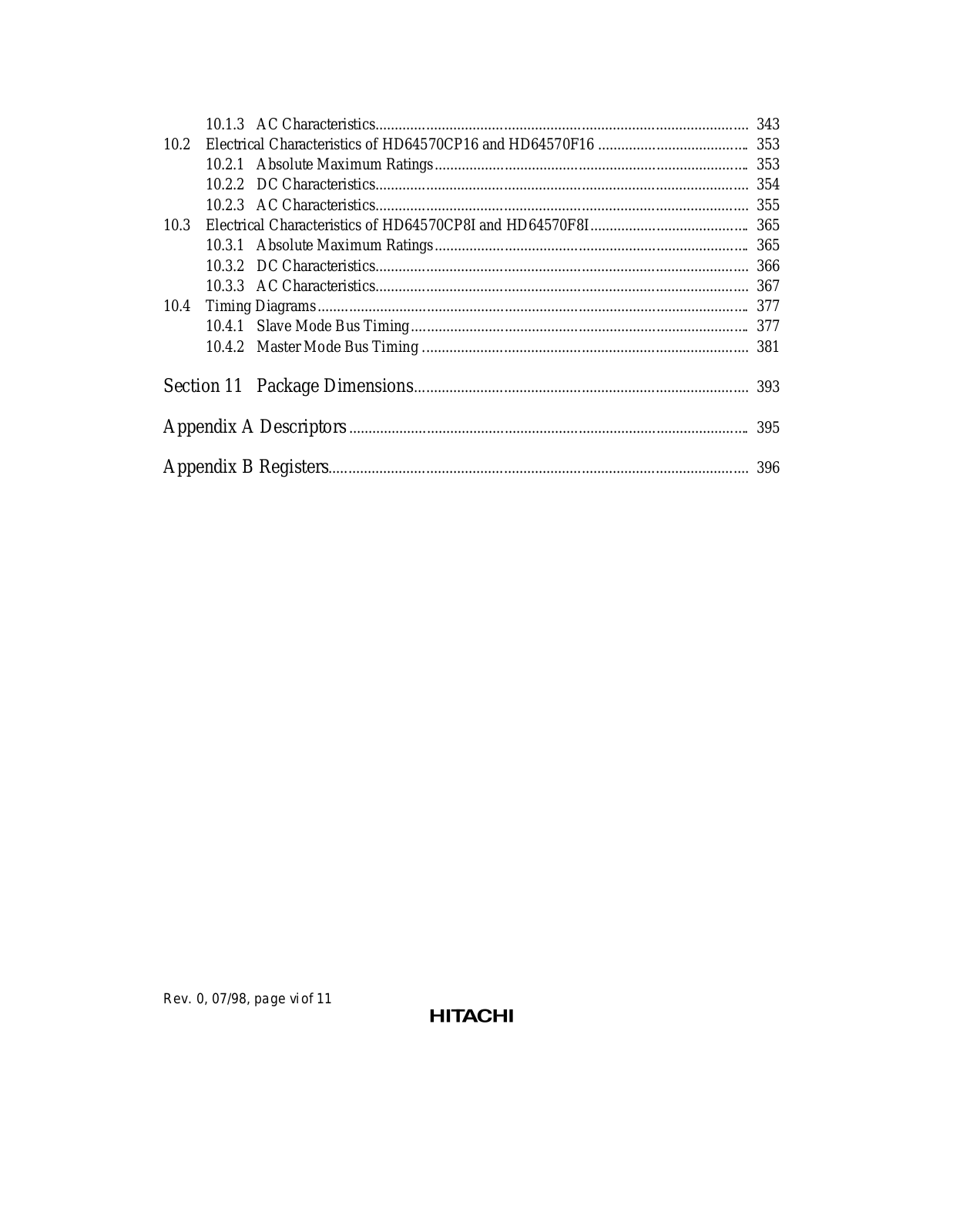
10.1.3

AC Characteristics................................................................................................

343

10.2 Electrical Characteristics of HD64570CP16 and HD64570F16 .......................................

353

10.2.1

Absolute Maximum Ratings.................................................................................

353

10.2.2

DC Characteristics................................................................................................

354

10.2.3

AC Characteristics................................................................................................

355

10.3 Electrical Characteristics of HD64570CP8I and HD64570F8I.........................................

365

10.3.1

Absolute Maximum Ratings.................................................................................

365

10.3.2

DC Characteristics................................................................................................

366

10.3.3

AC Characteristics................................................................................................

367

10.4 Timing Diagrams ...............................................................................................................

377

10.4.1

Slave Mode Bus Timing .......................................................................................

377

10.4.2

Master Mode Bus Timing ....................................................................................

381

Section 11

Package Dimensions......................................................................................

393

Appendix A Descriptors .......................................................................................................

395

Appendix B Registers............................................................................................................

396

Rev. 0, 07/98, page vi of 11

Section 1 Overview

1.1Overview

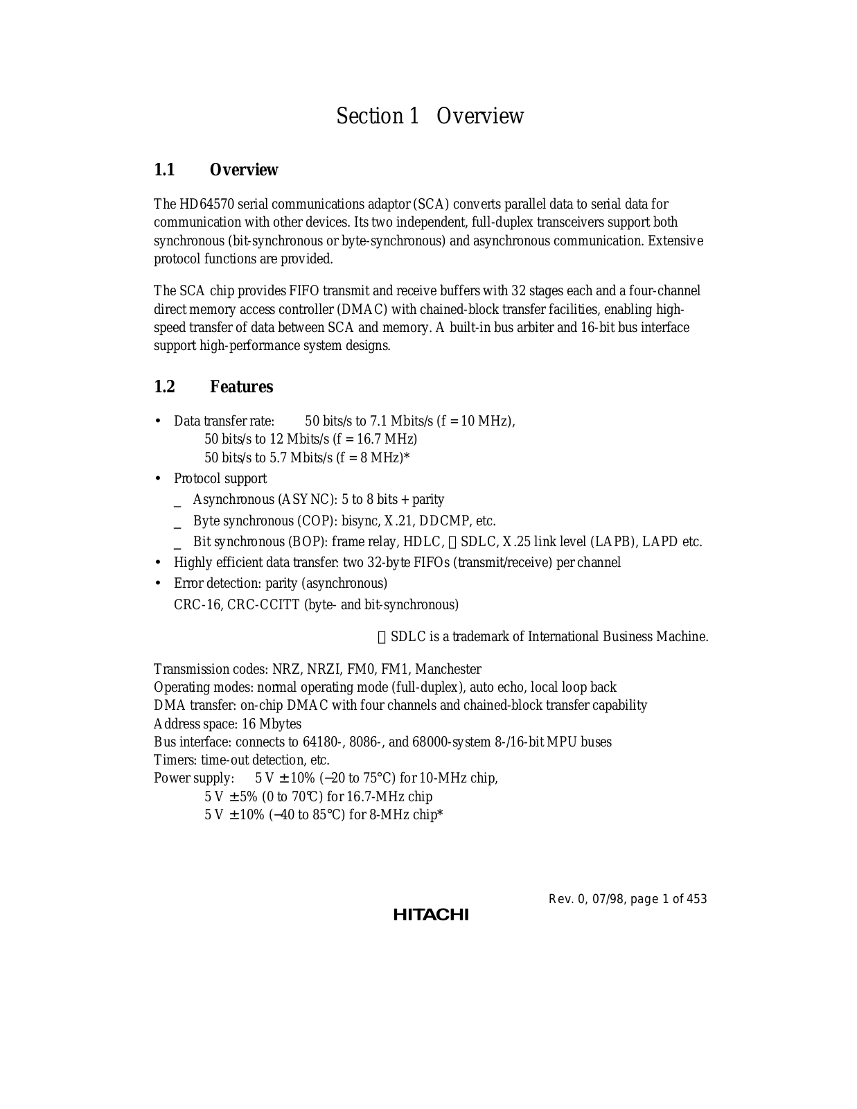
The HD64570 serial communications adaptor (SCA) converts parallel data to serial data for communication with other devices. Its two independent, full-duplex transceivers support both synchronous (bit-synchronous or byte-synchronous) and asynchronous communication. Extensive protocol functions are provided.

The SCA chip provides FIFO transmit and receive buffers with 32 stages each and a four-channel direct memory access controller (DMAC) with chained-block transfer facilities, enabling highspeed transfer of data between SCA and memory. A built-in bus arbiter and 16-bit bus interface support high-performance system designs.

1.2Features

Data transfer rate: 50 bits/s to 7.1 Mbits/s (f = 10 MHz), 50 bits/s to 12 Mbits/s (f = 16.7 MHz)

50 bits/s to 5.7 Mbits/s (f = 8 MHz)*

Protocol support

_ Asynchronous (ASYNC): 5 to 8 bits + parity

_ Byte synchronous (COP): bisync, X.21, DDCMP, etc.

_ Bit synchronous (BOP): frame relay, HDLC, SDLC, X.25 link level (LAPB), LAPD etc.

Highly efficient data transfer: two 32-byte FIFOs (transmit/receive) per channel

Error detection: parity (asynchronous)

CRC-16, CRC-CCITT (byteand bit-synchronous)

SDLC is a trademark of International Business Machine.

Transmission codes: NRZ, NRZI, FM0, FM1, Manchester

Operating modes: normal operating mode (full-duplex), auto echo, local loop back DMA transfer: on-chip DMAC with four channels and chained-block transfer capability Address space: 16 Mbytes

Bus interface: connects to 64180-, 8086-, and 68000-system 8-/16-bit MPU buses Timers: time-out detection, etc.

Power supply: 5 V ± 10% (20 to 75°C) for 10-MHz chip, 5 V ± 5% (0 to 70°C) for 16.7-MHz chip

5 V ± 10% (40 to 85°C) for 8-MHz chip*

Rev. 0, 07/98, page 1 of 453

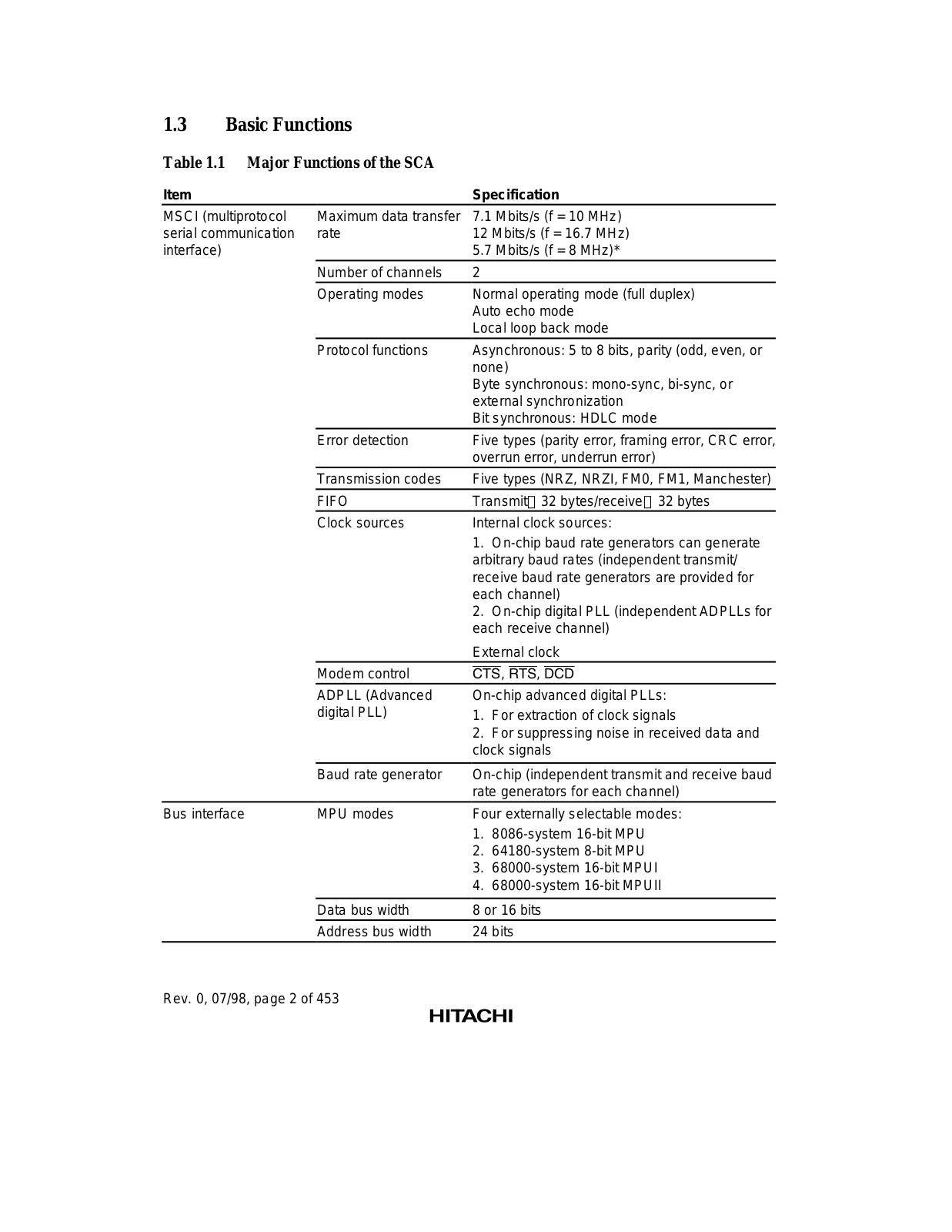
1.3Basic Functions

Table 1.1 Major Functions of the SCA

Item


Specification


MSCI (multiprotocol

Maximum data transfer

7.1 Mbits/s (f = 10 MHz)

serial communication

rate

12 Mbits/s (f = 16.7 MHz)

interface)


5.7 Mbits/s (f = 8 MHz)*


Number of channels

2


Operating modes

Normal operating mode (full duplex)


Auto echo mode


Local loop back mode


Protocol functions

Asynchronous: 5 to 8 bits, parity (odd, even, or


none)


Byte synchronous: mono-sync, bi-sync, or


external synchronization


Bit synchronous: HDLC mode


Error detection

Five types (parity error, framing error, CRC error,


overrun error, underrun error)


Transmission codes

Five types (NRZ, NRZI, FM0, FM1, Manchester)


FIFO

Transmit 32 bytes/receive 32 bytes


Clock sources

Internal clock sources:


1.

On-chip baud rate generators can generate


arbitrary baud rates (independent transmit/


receive baud rate generators are provided for


each channel)


2.

On-chip digital PLL (independent ADPLLs for


each receive channel)


External clock


Modem control

CTS, RTS, DCD


ADPLL (Advanced

On-chip advanced digital PLLs:


digital PLL)

1.

For extraction of clock signals


2.

For suppressing noise in received data and


clock signals


Baud rate generator

On-chip (independent transmit and receive baud


rate generators for each channel)


Bus interface

MPU modes

Four externally selectable modes:


1.

8086-system 16-bit MPU


2.

64180-system 8-bit MPU


3.

68000-system 16-bit MPUI


4.

68000-system 16-bit MPUII


Data bus width

8 or 16 bits


Address bus width

24 bits


Rev. 0, 07/98, page 2 of 453

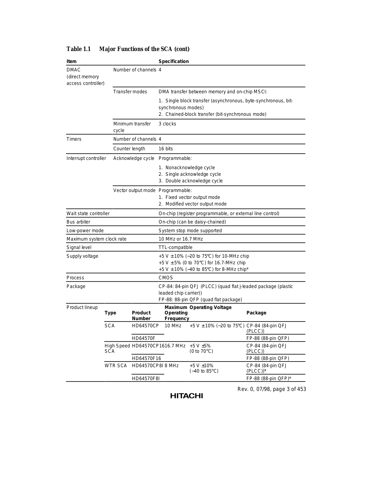
Table 1.1 Major Functions of the SCA (cont)

Item


Specification

DMAC

Number of channels 4


(direct memory


access controller)


Transfer modes

DMA transfer between memory and on-chip MSCI:


1.

Single block transfer (asynchronous, byte-synchronous, bit-


synchronous modes)


2.

Chained-block transfer (bit-synchronous mode)


Minimum transfer

3 clocks


cycle


Timers

Number of channels 4


Counter length

16 bits


Interrupt controller

Acknowledge cycle

Programmable:


1.

Nonacknowledge cycle


2.

Single acknowledge cycle


3.

Double acknowledge cycle


Vector output mode Programmable:


1. Fixed vector output mode


2. Modified vector output mode


Wait state controller

On-chip (register programmable, or external line control)

Bus arbiter

On-chip (can be daisy-chained)


Low-power mode

System stop mode supported


Maximum system clock rate

10 MHz or 16.7 MHz

Signal level

TTL-compatible


Supply voltage

+5

V ± 10% (−20 to 75°C) for 10-MHz chip


+5

V ± 5% (0 to 70°C) for 16.7-MHz chip


+5

V ± 10% (−40 to 85°C) for 8-MHz chip*

Process

CMOS


Package

CP-84: 84-pin QFJ (PLCC) (quad flat j-leaded package (plastic


leaded chip carrier))


FP-88: 88-pin QFP (quad flat package)


Product lineup


Maximum

Operating Voltage


Type

Product

Operating


Package


Number

Frequency


SCA

HD64570CP

10 MHz

+5 V ± 10% (−20 to 75°C) CP-84 (84-pin QFJ


(PLCC))


HD64570F


FP-88 (88-pin QFP)


High Speed HD64570CP1616.7 MHz

+5 V ±5%

CP-84 (84-pin QFJ


SCA


(0 to 70°C)

(PLCC))


HD64570F16


FP-88 (88-pin QFP)


WTR SCA

HD64570CP8I

8 MHz

+5 V ±10%

CP-84 (84-pin QFJ


(−40 to 85°C)

(PLCC))*


HD64570F8I


FP-88 (88-pin QFP)*

Rev. 0, 07/98, page 3 of 453

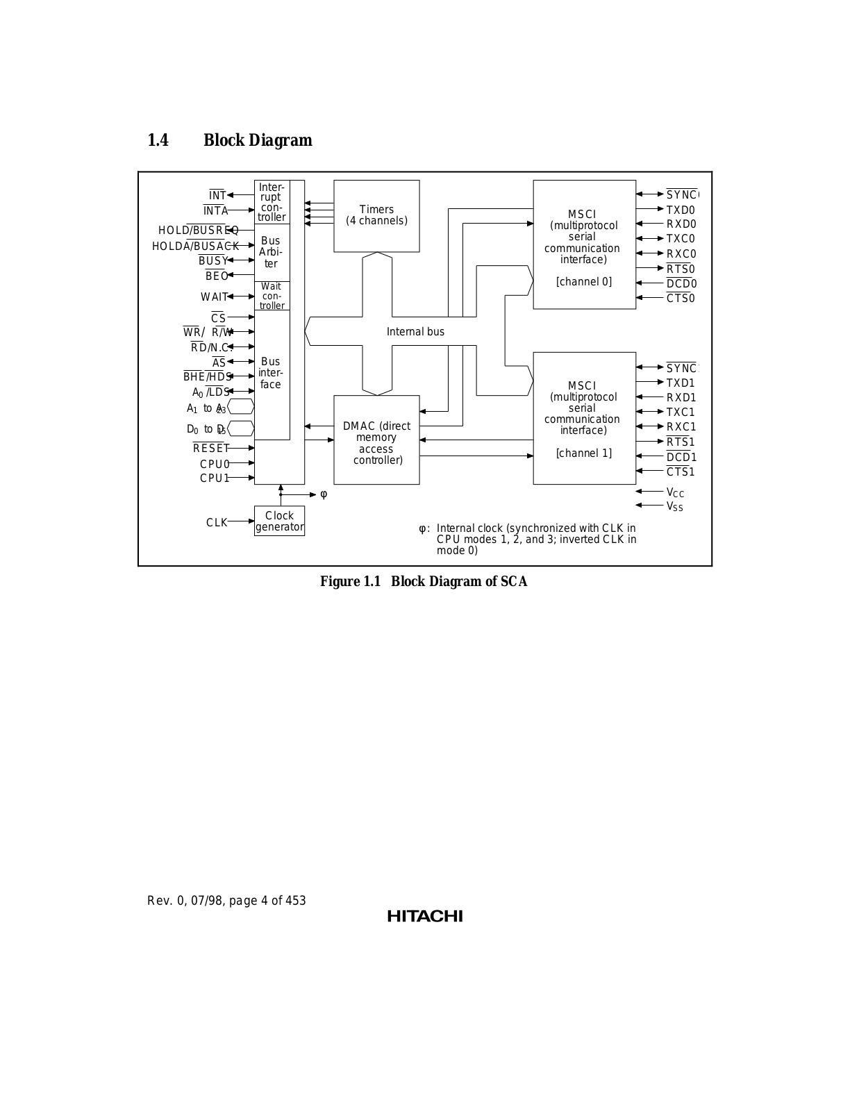
1.4Block Diagram


INT

Inter-


SYNC


rupt


INTA

con-

Timers

MSCI

TXD0


troller

(4 channels)

RXD0

HOLD/BUSREQ


(multiprotocol


Bus


serial

TXC0

HOLDA/BUSACK


Arbi-


communication

RXC0


BUSY


interface)


ter


RTS0


BEO


[channel 0]


Wait


DCD0


WAIT


con-


CTS0


troller


CS


WR/ R/W


Internal bus


RD/N.C.


AS

Bus


SYNC

BHE/HDS

inter-


TXD1

face


MSCI

A0 /LDS


(multiprotocol

RXD1

A1

to A23


serial

TXC1


communication

D0

to D15


DMAC (direct

RXC1


interface)

RESET


memory


RTS1


access

[channel 1]


DCD1


CPU0


controller)


CTS1


CPU1


φ


VCC


Clock


VSS


CLK


φ : Internal clock (synchronized with CLK in


generator


CPU modes 1, 2, and 3; inverted CLK in


mode 0)


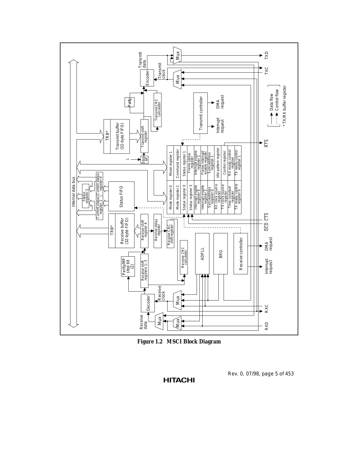
Figure 1.1 Block Diagram of SCA

Rev. 0, 07/98, page 4 of 453

HITACHI HD64570 SCA User Manual


Internal data bus


Status


register 2


Current status Current status


register 1

register 0


TRB*


TRB*


Receive buffer

Status FIFO

Transmit buffer


Parity/MP

(32-byte FIFO)


(32-byte FIFO)


1


stop bit


Parity


(2)


1Figure


Receive


Receive delay


Transmit CRC

Transmit


data


Receive shift


Receive shift


Stop

Transmit shift


data


Decoder


Encoder


2.

Mux

Receive


register


calculator

Transmit


MSCI


clock


clock


Receive CRC

Mode register 0

Mode register 1


shift register


Mux

Mux


Mode register 2

Command register


Mux

Mux

Block


Receive CRC


Status register 0

Status register 1


calculator


Frame status


Status register 3


register


Interrupt enable

Interrupt enable


Diagram


ADPLL


register 0

register 1

Transmit controller


Interrupt enable

Frame interrupt


register 2

enable register


Sync/address

Sync/address


register 0

register 1


RX clock source

Idle pattern register

Interrupt

DMA


BRG


register


TX clock source

Control register

request

request


register


.Rev


Time constant

RX ready control


register


register


TX ready control

TX ready control


07/98, 0,


Receive controller

register 0

register 1


page

RXD

RXC

Interrupt

DMA

DCD CTS


RTS


TXC

TXD


request

request


Data flow


5


Control flow


of


* TX/RX buffer register


453


Address bus/data bus


DAR:

Destination address register


BAR:

Buffer address register


SAR:

Source address register


FCT

CPB:

Chain pointer base


DAR


CDA:

Current descriptor address register


EDA:

Error descriptor address register


(24)


DSR


BFL:

Receive buffer length


BAR


DIR

BCR:

Byte count register


SAR (24)


DMR

FCT:

End-of-frame interrupt counter

CPB

(8)

Reserved

DSR:

DMA status register


DCR

DIR:

DMA interrupt enable register


CDA

(16)

DMR: DMA mode register


DCR: DMA command register


EDA

(16)


BFL

(16)*


Request and

DMA request


BCR

(16)


signal


priority control


Comparator

(16)

DMA execution


Incrementer/

control


Bus control signals


decrementer

(24)


Interrupt request signals


Single-address transfer control signal


(to MSCI)


* Channels 0 and 2 only

Numbers in parentheses are


numbers of bits.


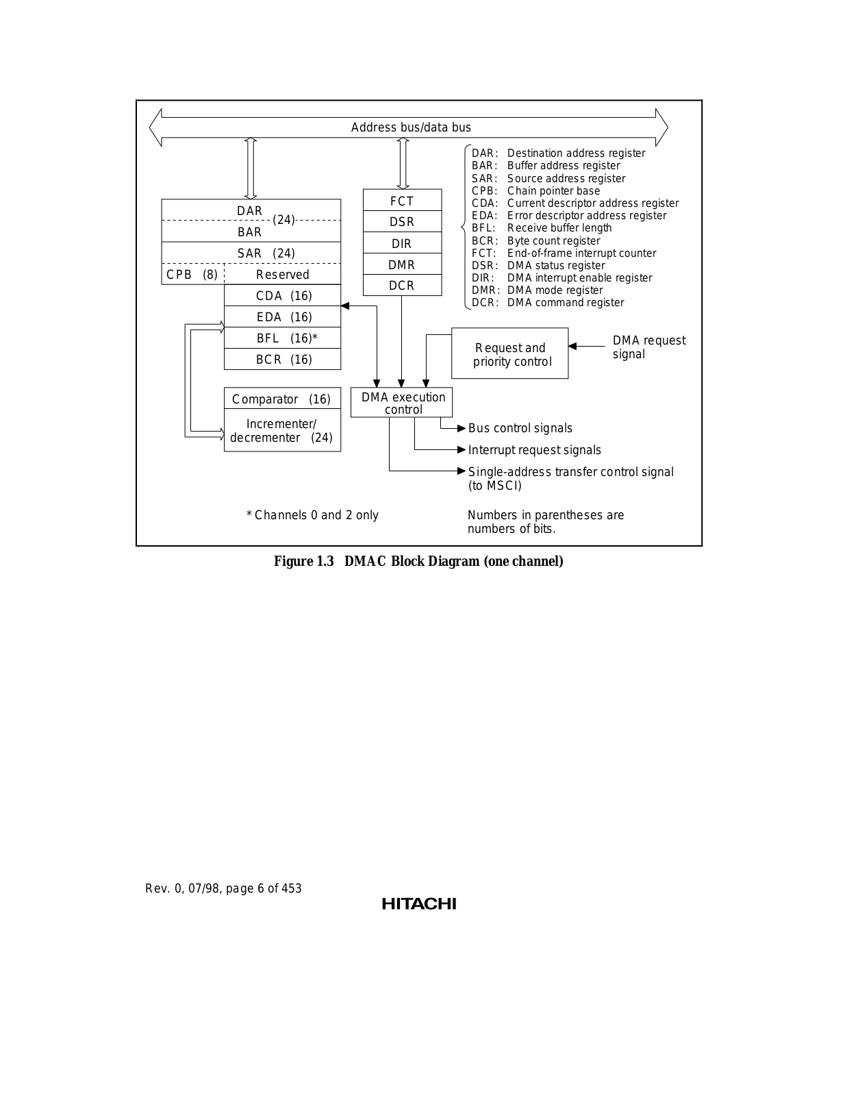
Figure 1.3 DMAC Block Diagram (one channel)

Rev. 0, 07/98, page 6 of 453

Internal data bus

Timer expand prescale register (TEPR)


Clock

Timer constant

Timer up-


register

counter


(TCONR)

(TCNT)


Counter

Comparator

reset

T0IRQ

T1IRQ

T2IRQ

T3IRQ

— —


ECKS2ECKS1ECKS0


3


Divider


Selector

8

.


20 – 27


.


BC*

.


– N


φ


N =


–. 8


CMF ECMI — TME — — — —

Timer control/status register (TCSR)

* Base clock

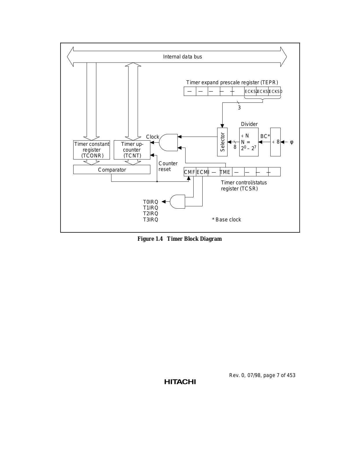
Figure 1.4 Timer Block Diagram

Rev. 0, 07/98, page 7 of 453


Internal address bus/data bus


Wait control register L

Physical address boundary


(WCRL)

register 0 (PABR0)

Wait control unit

Wait control register M

Physical address boundary

register 1 (PABR1)


(WCRM)


Wait control register H


(WCRH)

WAIT line


Wait control signal


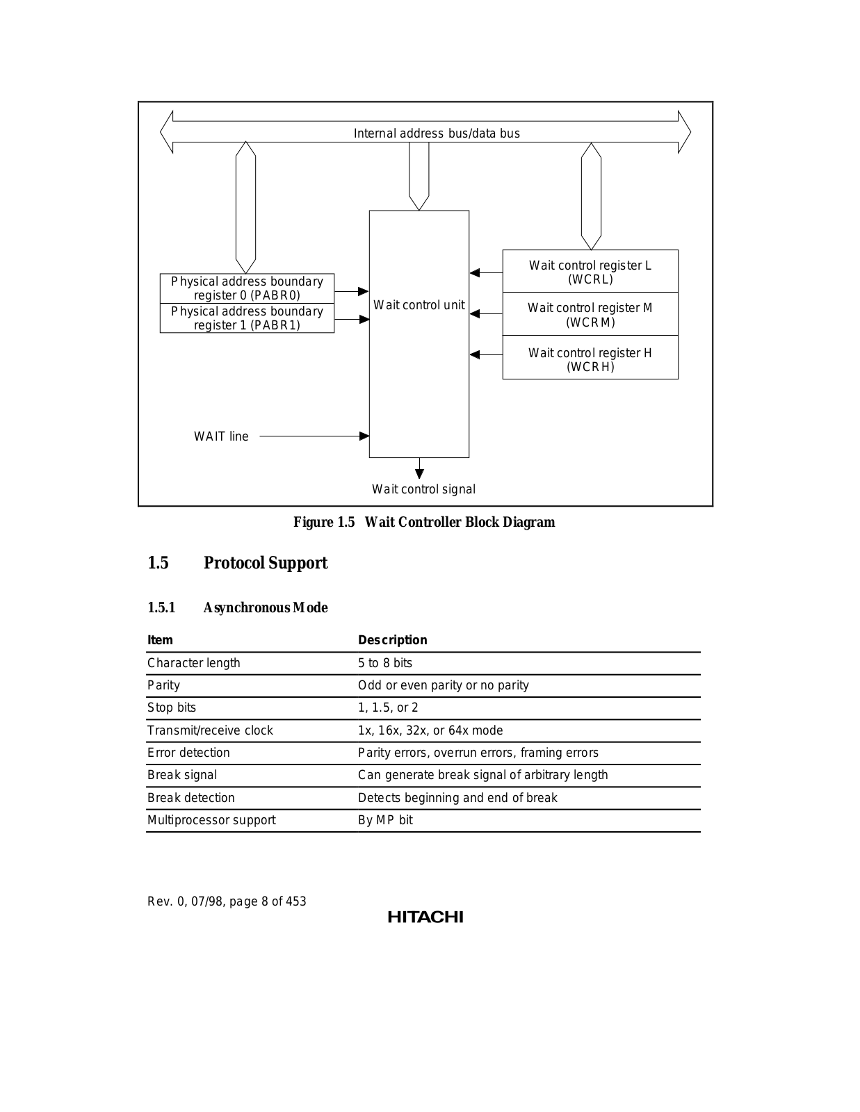
Figure 1.5 Wait Controller Block Diagram

1.5Protocol Support

1.5.1Asynchronous Mode

Item

Description

Character length

5 to 8 bits


Parity

Odd or even parity or no parity


Stop bits

1, 1.5, or 2


Transmit/receive clock

1x, 16x, 32x, or 64x mode


Error detection

Parity errors, overrun errors, framing errors


Break signal

Can generate break signal of arbitrary length


Break detection

Detects beginning and end of break


Multiprocessor support

By MP bit


Rev. 0, 07/98, page 8 of 453

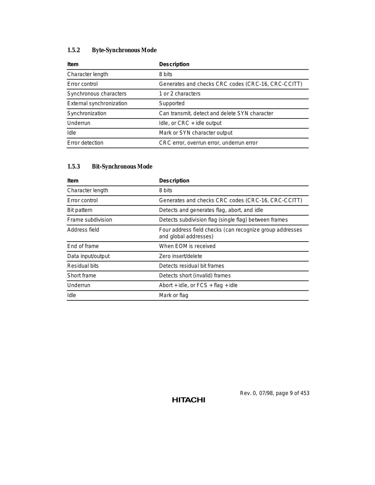
1.5.2Byte-Synchronous Mode

Item

Description

Character length

8 bits


Error control

Generates and checks CRC codes (CRC-16, CRC-CCITT)


Synchronous characters

1 or 2 characters


External synchronization

Supported


Synchronization

Can transmit, detect and delete SYN character


Underrun

Idle, or CRC + idle output


Idle

Mark or SYN character output


Error detection

CRC error, overrun error, underrun error


1.5.3Bit-Synchronous Mode

Item

Description

Character length

8 bits


Error control

Generates and checks CRC codes (CRC-16, CRC-CCITT)


Bit pattern

Detects and generates flag, abort, and idle


Frame subdivision

Detects subdivision flag (single flag) between frames


Address field

Four address field checks (can recognize group addresses


and global addresses)


End of frame

When EOM is received


Data input/output

Zero insert/delete


Residual bits

Detects residual bit frames


Short frame

Detects short (invalid) frames


Underrun

Abort + idle, or FCS + flag + idle


Idle

Mark or flag


Rev. 0, 07/98, page 9 of 453

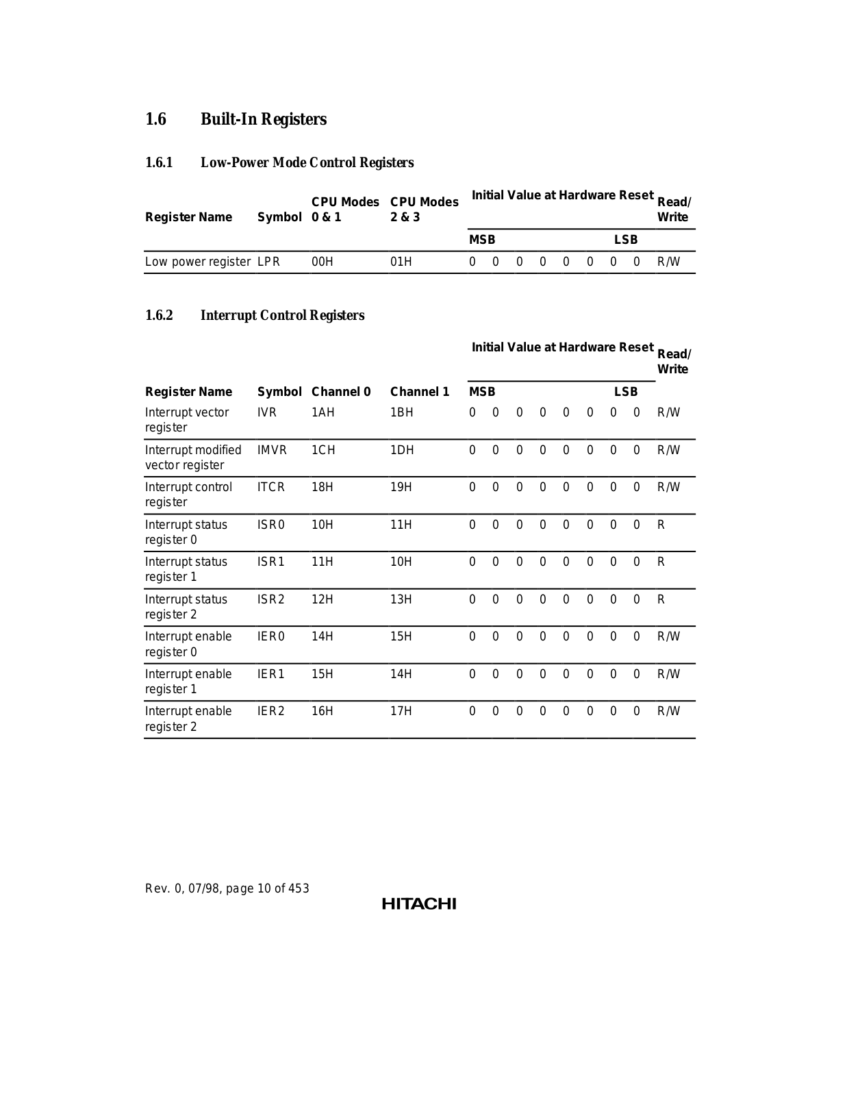
1.6Built-In Registers

1.6.1Low-Power Mode Control Registers


CPU Modes

CPU Modes

Initial Value at Hardware Reset Read/

Register Name

Symbol

0 & 1

2 & 3


Write


MSB

LSB


Low power register

LPR

00H

01H

0 0 0 0 0

0 0 0 R/W


1.6.2Interrupt Control Registers

Initial Value at Hardware Reset Read/


Write

Register Name

Symbol

Channel 0

Channel 1

MSB


LSB


Interrupt vector

IVR

1AH

1BH

0

0

0

0

0

0

0

0

R/W

register


Interrupt modified

IMVR

1CH

1DH

0

0

0

0

0

0

0

0

R/W

vector register


Interrupt control

ITCR

18H

19H

0

0

0

0

0

0

0

0

R/W

register


Interrupt status

ISR0

10H

11H

0

0

0

0

0

0

0

0

R

register 0


Interrupt status

ISR1

11H

10H

0

0

0

0

0

0

0

0

R

register 1


Interrupt status

ISR2

12H

13H

0

0

0

0

0

0

0

0

R

register 2


Interrupt enable

IER0

14H

15H

0

0

0

0

0

0

0

0

R/W

register 0


Interrupt enable

IER1

15H

14H

0

0

0

0

0

0

0

0

R/W

register 1


Interrupt enable

IER2

16H

17H

0

0

0

0

0

0

0

0

R/W

register 2


Rev. 0, 07/98, page 10 of 453

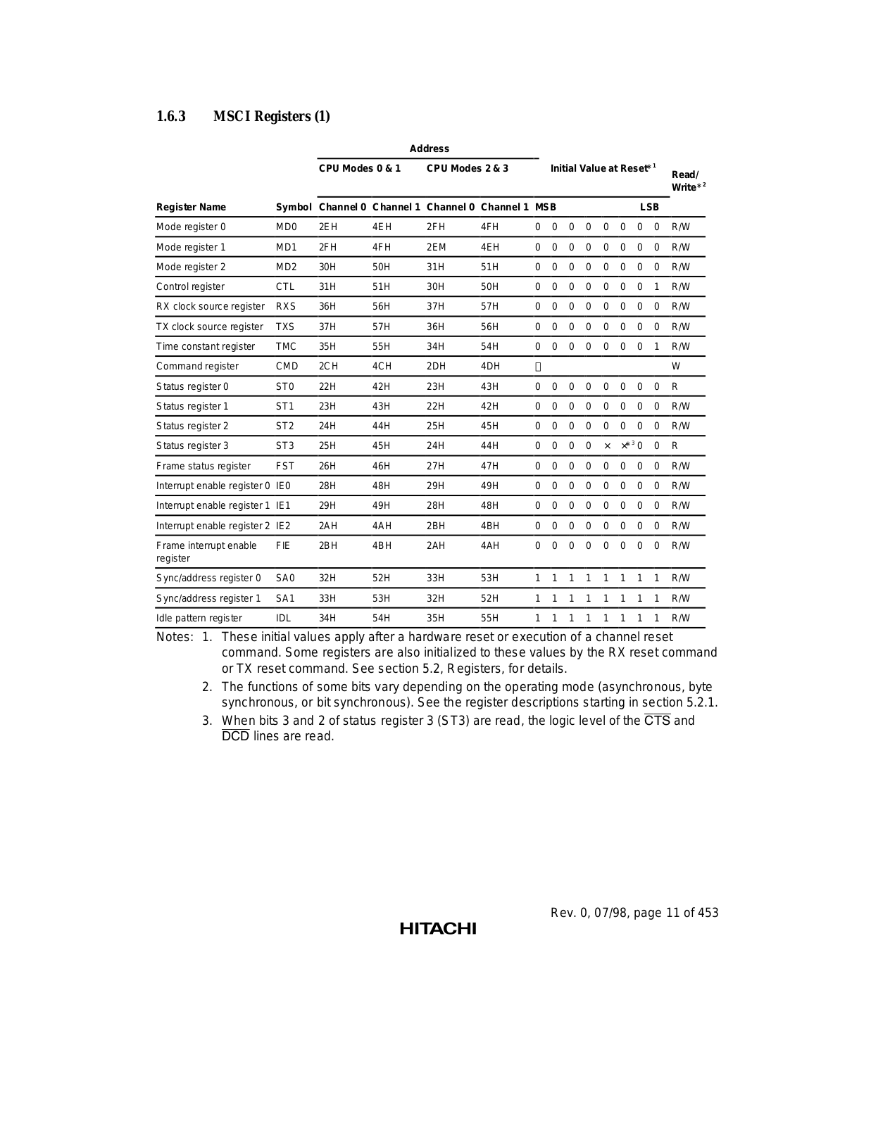
1.6.3MSCI Registers (1)


Address


CPU Modes 0 & 1

CPU Modes 2 & 3


Initial Value at Reset*1

Read/


Write*2


Register Name

Symbol

Channel 0

Channel 1

Channel 0

Channel 1

MSB


LSB


Mode register 0

MD0

2EH

4EH

2FH

4FH

0

0

0

0

0

0

0

0

R/W


Mode register 1

MD1

2FH

4FH

2EM

4EH

0

0

0

0

0

0

0

0

R/W


Mode register 2

MD2

30H

50H

31H

51H

0

0

0

0

0

0

0

0

R/W


Control register

CTL

31H

51H

30H

50H

0

0

0

0

0

0

0

1

R/W


RX clock source register

RXS

36H

56H

37H

57H

0

0

0

0

0

0

0

0

R/W


TX clock source register

TXS

37H

57H

36H

56H

0

0

0

0

0

0

0

0

R/W


Time constant register

TMC

35H

55H

34H

54H

0

0

0

0

0

0

0

1

R/W


Command register

CMD

2CH

4CH

2DH

4DH


W


Status register 0

ST0

22H

42H

23H

43H

0

0

0

0

0

0

0

0

R


Status register 1

ST1

23H

43H

22H

42H

0

0

0

0

0

0

0

0

R/W


Status register 2

ST2

24H

44H

25H

45H

0

0

0

0

0

0

0

0

R/W


Status register 3

ST3

25H

45H

24H

44H

0

0

0

0

×

×*3 0

0

R


Frame status register

FST

26H

46H

27H

47H

0

0

0

0

0

0

0

0

R/W


Interrupt enable register 0 IE0

28H

48H

29H

49H

0

0

0

0

0

0

0

0

R/W


Interrupt enable register 1 IE1

29H

49H

28H

48H

0

0

0

0

0

0

0

0

R/W


Interrupt enable register 2 IE2

2AH

4AH

2BH

4BH

0

0

0

0

0

0

0

0

R/W


Frame interrupt enable

FIE

2BH

4BH

2AH

4AH

0

0

0

0

0

0

0

0

R/W

register


Sync/address register 0

SA0

32H

52H

33H

53H

1

1

1

1

1

1

1

1

R/W


Sync/address register 1

SA1

33H

53H

32H

52H

1

1

1

1

1

1

1

1

R/W


Idle pattern register

IDL

34H

54H

35H

55H

1

1

1

1

1

1

1

1

R/W

Notes: 1. These initial values apply after a hardware reset or execution of a channel reset command. Some registers are also initialized to these values by the RX reset command or TX reset command. See section 5.2, Registers, for details.

2.The functions of some bits vary depending on the operating mode (asynchronous, byte synchronous, or bit synchronous). See the register descriptions starting in section 5.2.1.

3.When bits 3 and 2 of status register 3 (ST3) are read, the logic level of the CTS and DCD lines are read.

Rev. 0, 07/98, page 11 of 453

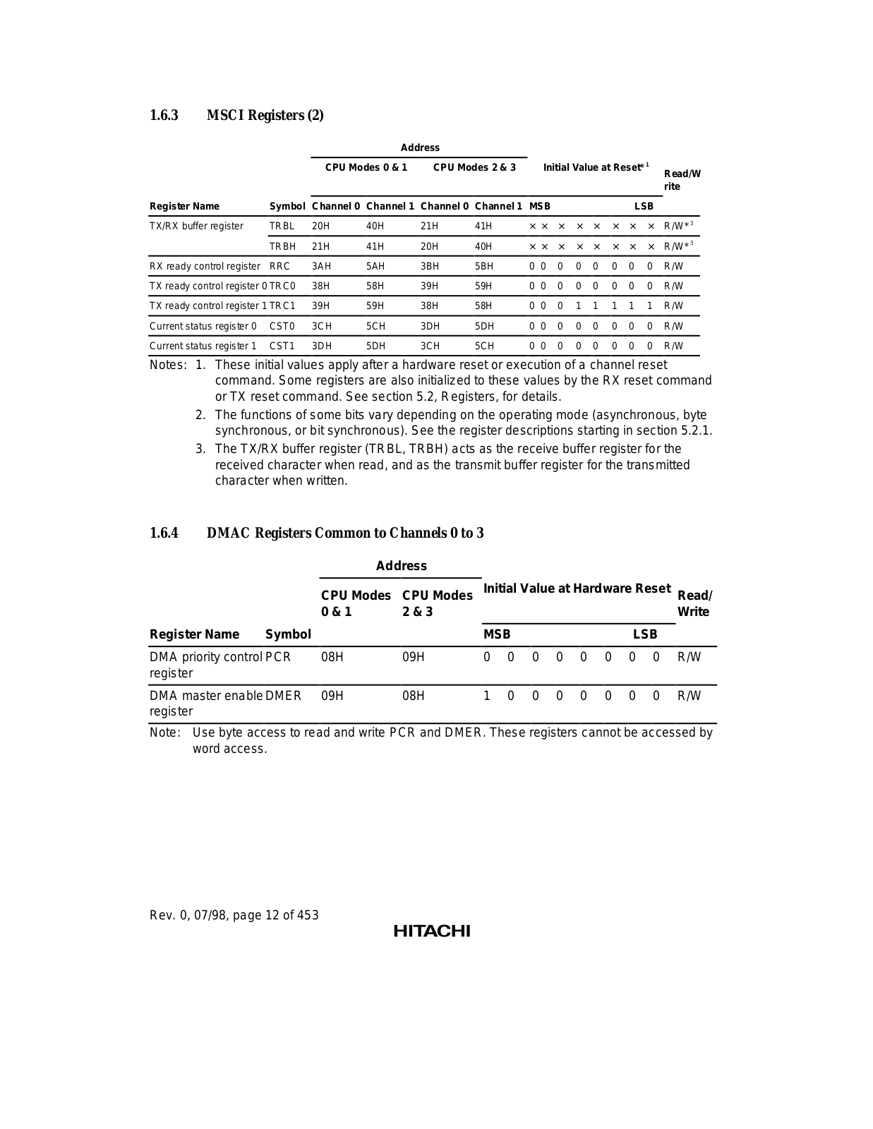
1.6.3MSCI Registers (2)


Address


CPU Modes 0 & 1

CPU Modes 2 & 3


Initial Value at Reset*1

Read/W


rite


Register Name

Symbol

Channel 0

Channel 1

Channel 0

Channel 1

MSB


LSB


TX/RX buffer register

TRBL

20H

40H

21H

41H

× ×

×

×

×

×

×

×

R/W*3


TRBH

21H

41H

20H

40H

× ×

×

×

×

×

×

×

R/W*3


RX ready control register

RRC

3AH

5AH

3BH

5BH

0

0

0

0

0

0

0

0

R/W


TX ready control register 0 TRC0

38H

58H

39H

59H

0

0

0

0

0

0

0

0

R/W


TX ready control register 1 TRC1

39H

59H

38H

58H

0

0

0

1

1

1

1

1

R/W


Current status register 0

CST0

3CH

5CH

3DH

5DH

0

0

0

0

0

0

0

0

R/W


Current status register 1

CST1

3DH

5DH

3CH

5CH

0

0

0

0

0

0

0

0

R/W

Notes: 1. These initial values apply after a hardware reset or execution of a channel reset command. Some registers are also initialized to these values by the RX reset command or TX reset command. See section 5.2, Registers, for details.

2.The functions of some bits vary depending on the operating mode (asynchronous, byte synchronous, or bit synchronous). See the register descriptions starting in section 5.2.1.

3.The TX/RX buffer register (TRBL, TRBH) acts as the receive buffer register for the received character when read, and as the transmit buffer register for the transmitted character when written.

1.6.4DMAC Registers Common to Channels 0 to 3


Address


CPU Modes

CPU Modes

Initial Value at Hardware Reset Read/


0 & 1

2 & 3


Write


Register Name Symbol


MSB


LSB


DMA priority control PCR

08H

09H

0

0

0

0

0

0

0

0

R/W

register


DMA master enable DMER

09H

08H

1

0

0

0

0

0

0

0

R/W

register


Note: Use byte access to read and write PCR and DMER. These registers cannot be accessed by word access.

Rev. 0, 07/98, page 12 of 453

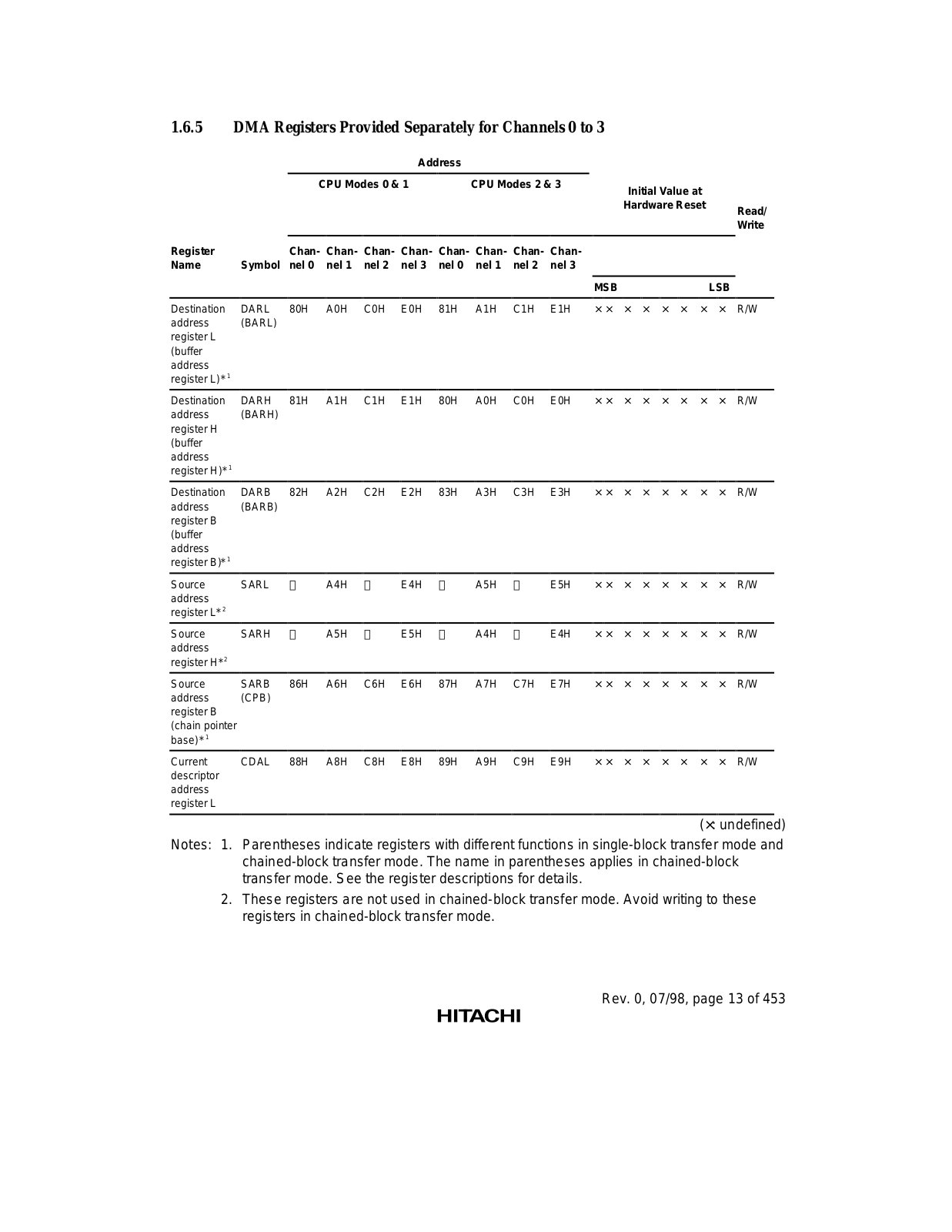
1.6.5DMA Registers Provided Separately for Channels 0 to 3

Address


CPU Modes 0

& 1

CPU Modes 2 & 3

Initial Value at


Hardware Reset


Register


ChanChanChanChanChanChanChanChan-


Name

Symbol nel 0 nel 1 nel 2

nel 3

nel 0 nel 1 nel 2 nel 3


MSB

LSB

Read/

Write

Destination

DARL

80H

A0H

C0H

E0H

81H

A1H

C1H

E1H

× ×

×

×

×

×

×

×

R/W

address

(BARL)


register L


(buffer


address


register L)*1


Destination

DARH

81H

A1H

C1H

E1H

80H

A0H

C0H

E0H

× ×

×

×

×

×

×

×

R/W

address

(BARH)


register H


(buffer


address


register H)*1


Destination

DARB

82H

A2H

C2H

E2H

83H

A3H

C3H

E3H

× ×

×

×

×

×

×

×

R/W

address

(BARB)


register B


(buffer


address


register B)*1


Source

SARL


A4H


E4H


A5H


E5H

× ×

×

×

×

×

×

×

R/W

address


register L*2


Source

SARH


A5H


E5H


A4H


E4H

× ×

×

×

×

×

×

×

R/W

address


register H*2


Source

SARB

86H

A6H

C6H

E6H

87H

A7H

C7H

E7H

× ×

×

×

×

×

×

×

R/W

address

(CPB)


register B


(chain pointer


base)*1


Current

CDAL

88H

A8H

C8H

E8H

89H

A9H

C9H

E9H

× ×

×

×

×

×

×

×

R/W

descriptor


address


register L


(×: undefined)

Notes: 1. Parentheses indicate registers with different functions in single-block transfer mode and chained-block transfer mode. The name in parentheses applies in chained-block transfer mode. See the register descriptions for details.

2.These registers are not used in chained-block transfer mode. Avoid writing to these registers in chained-block transfer mode.

Rev. 0, 07/98, page 13 of 453

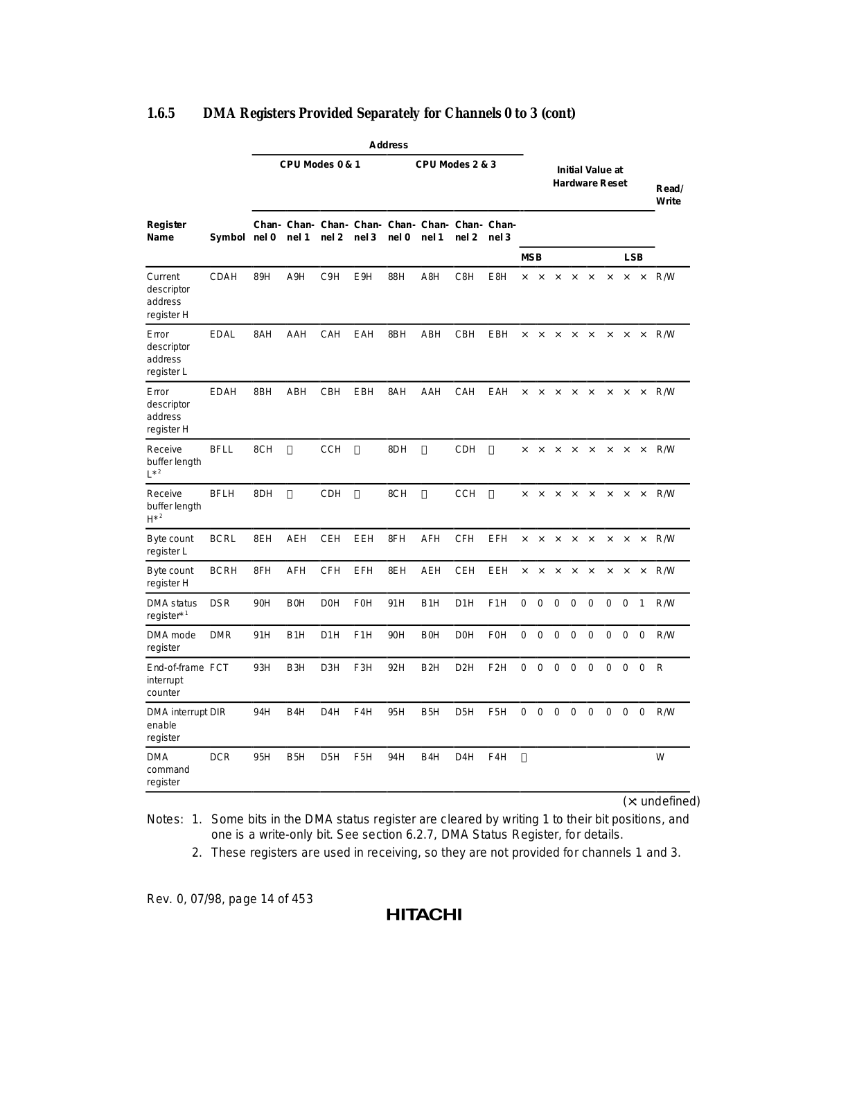
1.6.5DMA Registers Provided Separately for Channels 0 to 3 (cont)


Address


CPU Modes 0 & 1


CPU Modes 2 & 3


Initial Value at


Hardware Reset


Read/


Write


Register


ChanChanChanChanChanChanChanChan-


Name

Symbol

nel 0

nel 1

nel 2

nel 3

nel 0

nel 1

nel 2

nel 3


MSB


LSB


Current

CDAH

89H

A9H

C9H

E9H

88H

A8H

C8H

E8H

×

×

×

×

×

×

×

×

R/W

descriptor


address


register H


Error

EDAL

8AH

AAH

CAH

EAH

8BH

ABH

CBH

EBH

×

×

×

×

×

×

×

×

R/W

descriptor


address


register L


Error

EDAH

8BH

ABH

CBH

EBH

8AH

AAH

CAH

EAH

×

×

×

×

×

×

×

×

R/W

descriptor


address


register H


Receive

BFLL

8CH


CCH


8DH


CDH


×

×

×

×

×

×

×

×

R/W

buffer length


L*2


Receive

BFLH

8DH


CDH


8CH


CCH


×

×

×

×

×

×

×

×

R/W

buffer length


H*2


Byte count

BCRL

8EH

AEH

CEH

EEH

8FH

AFH

CFH

EFH

×

×

×

×

×

×

×

×

R/W

register L


Byte count

BCRH

8FH

AFH

CFH

EFH

8EH

AEH

CEH

EEH

×

×

×

×

×

×

×

×

R/W

register H


DMA status

DSR

90H

B0H

D0H

F0H

91H

B1H

D1H

F1H

0

0

0

0

0

0

0

1

R/W

register*1


DMA mode

DMR

91H

B1H

D1H

F1H

90H

B0H

D0H

F0H

0

0

0

0

0

0

0

0

R/W

register


End-of-frame FCT

93H

B3H

D3H

F3H

92H

B2H

D2H

F2H

0

0

0

0

0

0

0

0

R

interrupt


counter


DMA interrupt DIR

94H

B4H

D4H

F4H

95H

B5H

D5H

F5H

0

0

0

0

0

0

0

0

R/W

enable


register


DMA

DCR

95H

B5H

D5H

F5H

94H

B4H

D4H

F4H


W

command


register


(×: undefined)

Notes: 1. Some bits in the DMA status register are cleared by writing 1 to their bit positions, and one is a write-only bit. See section 6.2.7, DMA Status Register, for details.

2. These registers are used in receiving, so they are not provided for channels 1 and 3.

Rev. 0, 07/98, page 14 of 453

Loading...
+ 439 hidden pages