

INSTRUCTIONS-PARTS LIST
This manual contains important
warnings and information.
READ AND KEEP FOR REFERENCE.
INSTRUCTIONS
GMax 5900 Convertible
Airless Paint Sprayers
309411E
–For Portable Airless Spraying of Architectural Coatings and Paints –
5.5 HORSEPOWER, GASOLINE POWERED
3300 psi (228 bar, 22.8 MPa) Maximum Working Pressure
Model Series Description
233709 A Sprayer, gas powered
233710 A Sprayer, gas powered, with RAC X tip,
gun and hose
233711 A Sprayer, gas powered, with electric
motor kit
233712 A Same as 233711 except with ETL
approval to CSA and UL standards
233713 A Sprayer, gas powered, with Lo-Boy
suction set kit
233714 A Sprayer, gas powered, with RAC X tip,
gun and hose and Lo-Boy suction set kit
233715 A Sprayer, gas powered, with Lo-Boy
suction set kit and electric motor kit
233709
ti1852a
Related Manuals
Operator 309410. . . . . . . . . . . . . . . . . . . . . . . . . . .
Displacement Pump 309277. . . . . . . . . . . . . . . . .
Spray Gun 309639. . . . . . . . . . . . . . . . . . . . . . . . .
Spray Tip 309640. . . . . . . . . . . . . . . . . . . . . . . . . . .
AutoClean Kit 309450. . . . . . . . . . . . . . . . . . . . . . .
PC Board 309459. . . . . . . . . . . . . . . . . . . . . . . . . .
Electric Motor Kit 309469. . . . . . . . . . . . . . . . . . . .
Drain Valve Kit 308961. . . . . . . . . . . . . . . . . . . . . .
GRACO INC. P.O. BOX 1441 MINNEAPOLIS, MN 55440–1441
COPYRIGHT 2002, GRACO INC.
Graco Inc. is registered to I.S. EN ISO 9001
Table of Contents
Component Identification and Function 5. . . . . . . . . . . .
Maintenance 6. . . . . . . . . . . . . . . . . . . . . . . . . . . . . . . . . . .
Troubleshooting 7. . . . . . . . . . . . . . . . . . . . . . . . . . . . . . . .
Repair
Bearing Housing and Connecting Rod 9. . . . . . . . . . .
Drive Housing 10. . . . . . . . . . . . . . . . . . . . . . . . . . . . . . .
Pinion Assembly/Rotor/Field/Shaft/Clutch/Pulley 11.
ON/OFF Switch 13. . . . . . . . . . . . . . . . . . . . . . . . . . . . .
Pressure Control Repair 14. . . . . . . . . . . . . . . . . . . . . .
Displacement Pump Repair 16. . . . . . . . . . . . . . . . . . .
Parts
Basic Sprayer 18. . . . . . . . . . . . . . . . . . . . . . . . . . . . . . .
Pinion Assembly 21. . . . . . . . . . . . . . . . . . . . . . . . . . . .
Pressure Control 22. . . . . . . . . . . . . . . . . . . . . . . . . . . .
Wiring Schematic 23. . . . . . . . . . . . . . . . . . . . . . . . . . . .
Clutch Assembly 24. . . . . . . . . . . . . . . . . . . . . . . . . . . .
Complete Sprayer 24. . . . . . . . . . . . . . . . . . . . . . . . . . .
Lo-Boy Suction Set Kit 25. . . . . . . . . . . . . . . . . . . . . . .
Technical Data 25. . . . . . . . . . . . . . . . . . . . . . . . . . . . . . . .
Dimensions 25. . . . . . . . . . . . . . . . . . . . . . . . . . . . . . . . . . .
Graco Warranty 26. . . . . . . . . . . . . . . . . . . . . . . . . . . . . . .
Warnings and Cautions
Warning Symbol
WARNING
This symbol alerts you to the possibility of serious
injury or death if you do not follow the instructions.
The wallet-sized warning card provided with this pole gun should be kept with the operator at all times. The card
contains important treatment information should a fluid injection injury occur. Additional cards are available at no
charge from Graco Inc.
Caution Symbol
CAUTION
This symbol alerts you to the possibility of damage to
or destruction of equipment if you do not follow the
instructions.
2 309411
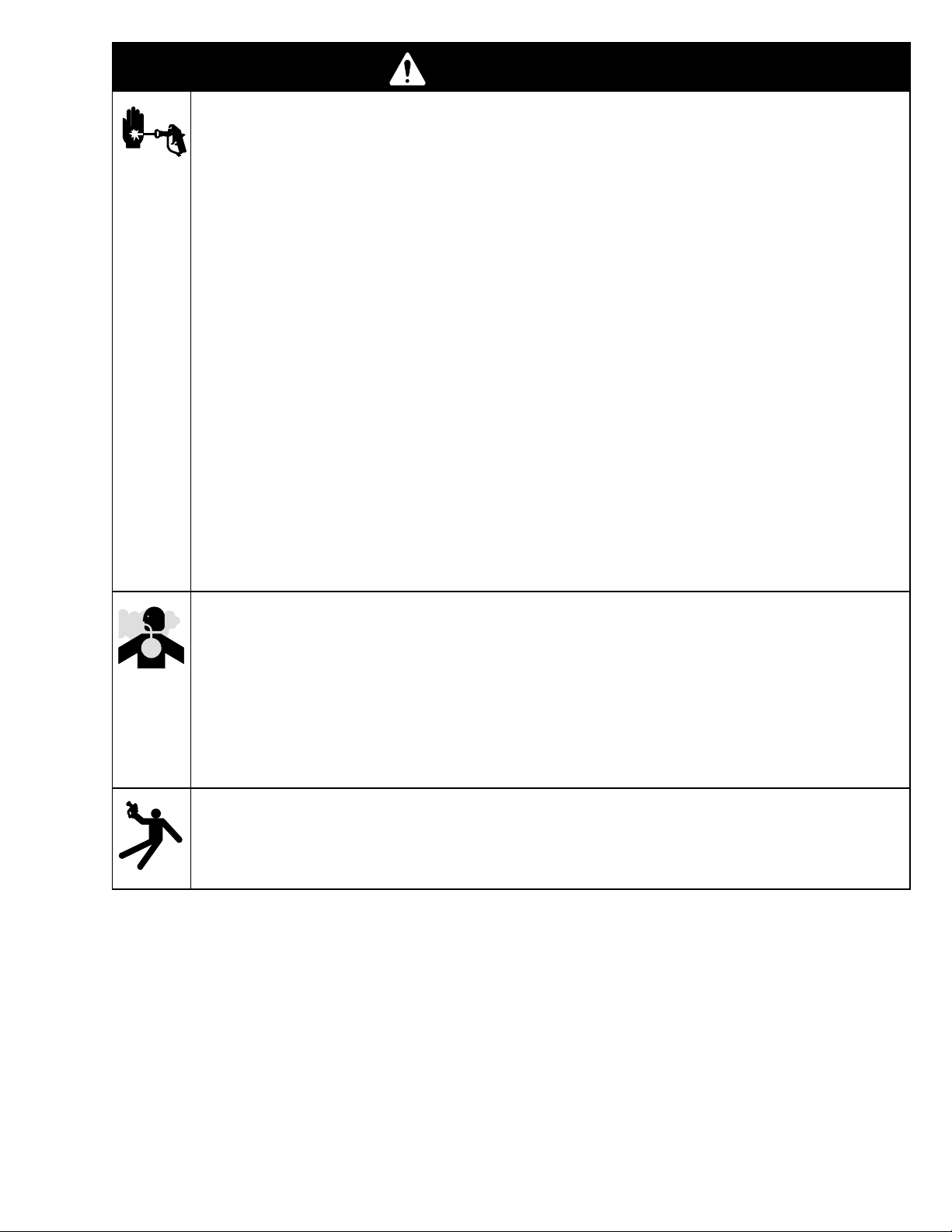
WARNING
SKIN INJECTION HAZARD
Spray from the spray tip, hose leaks or ruptured components can inject fluid into your body and cause
extremely serious injury, including the need for amputation. Splashing fluid in the eyes or on the skin
can also cause can also cause serious injury.
Fluid injected into the skin might look like just a cut, but it is a serious injury. Get immediate surgi-
cal treatment!
Do not point the spray tip at anyone or any part of the body.
Do not put hand or fingers over the spray tip, and do not stop or deflect fluid leaks with your hand,
body, glove or rag.
Do not “blow back” fluid; this is not an air spray system.
Always have the tip guard and the trigger guard on the in-line valve when spraying.
Be sure the trigger safety lever operates before operating the in-line valve.
Lock the trigger safety lever when you stop spraying.
Follow the Pressure Relief Procedure on page 6 when you are instructed to relieve pressure;
stop spraying; check, clean, or service any system equipment; or install or change spray tips.
Tighten all fluid connections before each use.
Check the hoses, tubes and couplings daily. Replace worn or damaged parts immediately. Perma-
nently coupled hoses cannot be repaired.
Handle and route hoses and tubes carefully. Keep hoses and tubes away from moving parts and
hot surfaces. Do not use the hoses to pull equipment. Do not expose Graco hoses to temperatures
above 150F (65C) or below –40F (–40C).
TOXIC FLUID HAZARD
Hazardous fluids or toxic fumes can cause a serious injury or death if the fluid is swallowed or
splashed in the eyes or on the skin or if the fumes are inhaled.
Know the specific hazards of the fluid you are using.
Store hazardous fluid in an approved container. Dispose hazardous fluid according to all local,
state and national guidelines.
Dress appropriately for your application. Wear protective eyewear, noise protection for the ears, a
personal respirator, gloves, and clothing.
RECOIL HAZARD
Due to the high pressure fluid emitted, a strong recoil action may occur when you trigger the pole gun.
If you are unprepared, your hand could be forced back toward your body or you could lose your balance and fall, resulting in serious injury.
3309411
INSTRUCTIONS
WARNING
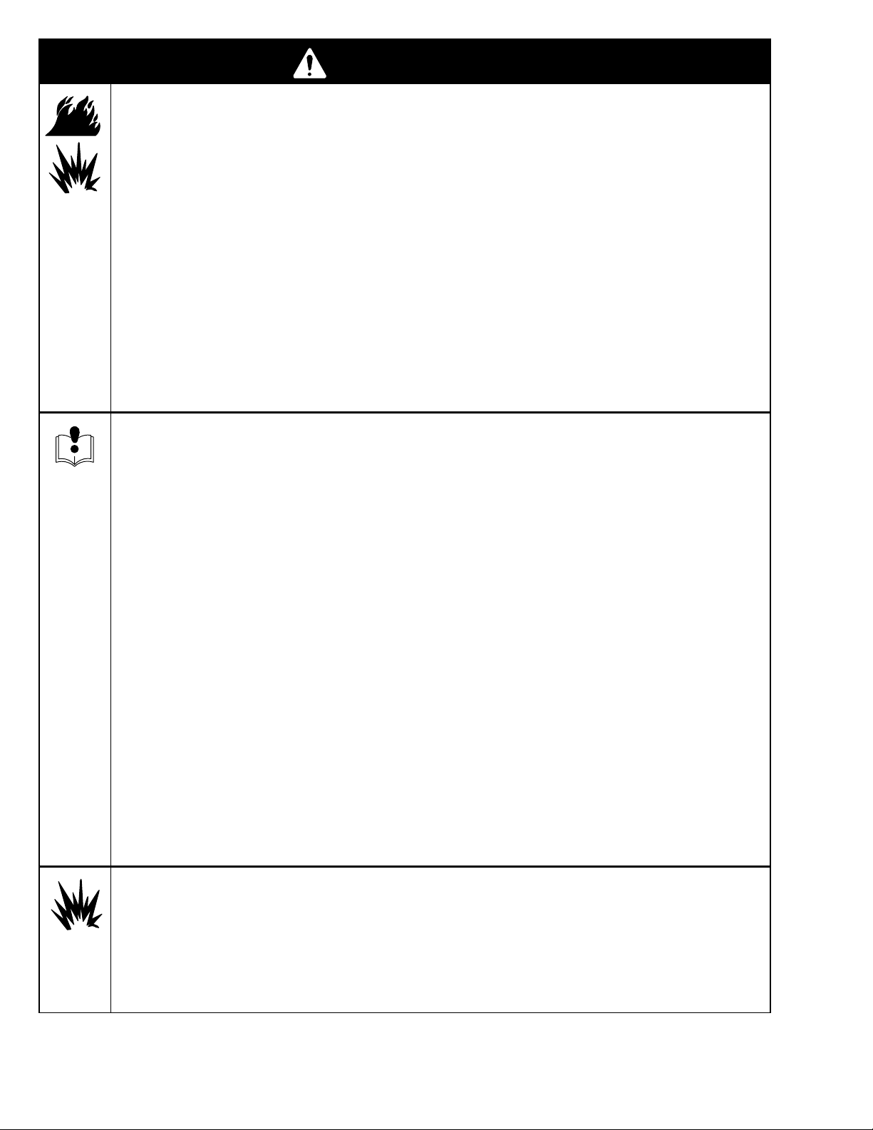
FIRE AND EXPLOSION HAZARD
Improper grounding, poor air ventilation, open flames, or sparks can cause a hazardous condition and
result in fire or explosion and serious injury.
Ground the equipment and the object being sprayed.
Provide fresh air ventilation to avoid the buildup of flammable fumes from solvent or the fluid being
sprayed.
Extinguish all the open flames or pilot lights in the spray area.
Electrically disconnect all the equipment in the spray area.
Keep the spray area free of debris, including solvent, rags, and gasoline.
Do not turn on or off any light switch in the spray area while operating or if fumes are present.
Do not smoke in the spray area.
Do not operate a gasoline engine in the spray area.
If there is any static sparking while using the equipment, stop spraying immediately. Identify and
correct the problem.
EQUIPMENT MISUSE HAZARD
Equipment misuse can cause the equipment to rupture, malfunction, or start unexpectedly and result
in serious injury.
This equipment is for professional use only.
Read all instruction manuals, tags, and labels before operating the equipment.
Use the equipment only for its intended purpose. If you are uncertain about the usage, call your
distributor.
Do not alter or modify this equipment. Use only genuine Graco parts and accessories.
Check the equipment daily. Repair or replace worn or damaged parts immediately.
Do not exceed the maximum working pressure of the lowest rated system component. This equip-
ment has a 3600 psi (25 MPa, 248 bar) maximum working pressure.
Route the hoses away from the traffic areas, sharp edges, moving parts, and hot surfaces. Do not
expose Graco hoses to temperatures above 150F (65C) or below –40F (–40C).
Do not use the hoses to pull the equipment.
Use fluids or solvents that are compatible with the equipment wetted parts. See the Technical
Data section of all the equipment manuals. Read the fluid and solvent manufacturer’s warnings.
Fluid hoses must have spring guards on both ends to protect them from rupture caused by kinks or
bends near the couplings.
Comply with all applicable local, state and national fire, electrical and other safety regulations.
Wear hearing protection when operating this equipment.
HAZARD OF USING FLUIDS CONTAINING HALOGENATED HYDROCARBONS
Never use 1,1,1-trichloroethane, methylene chloride, other halogenated hydrocarbon solvents or fluids
containing such solvents in this equipment. Such use could result in a serious chemical reaction, with
the possibility of explosion, which could cause death, serious injury and/or substantial property damage.
Consult your fluid suppliers to ensure that the fluids being used are compatible with aluminum and zinc
parts.
4 309411
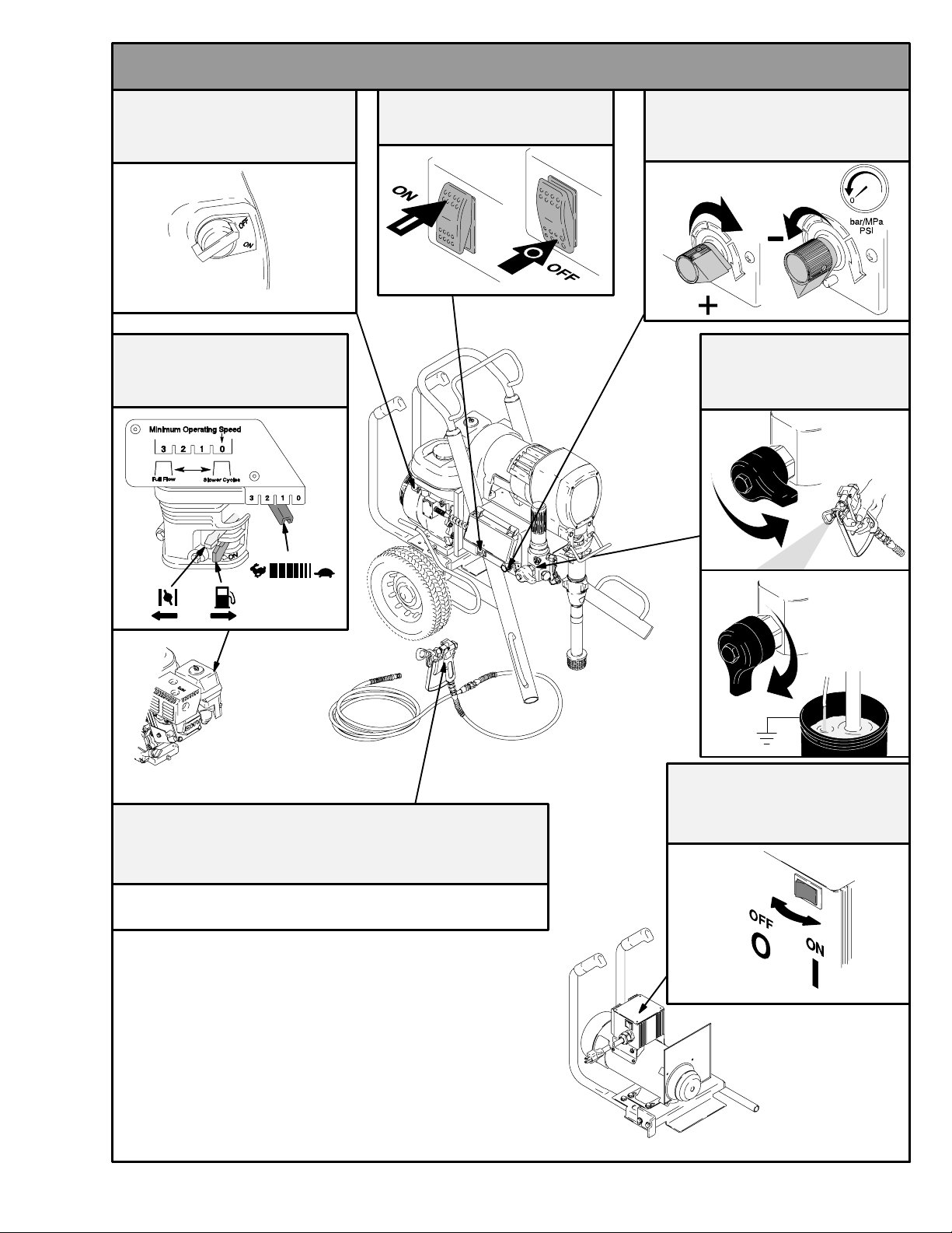
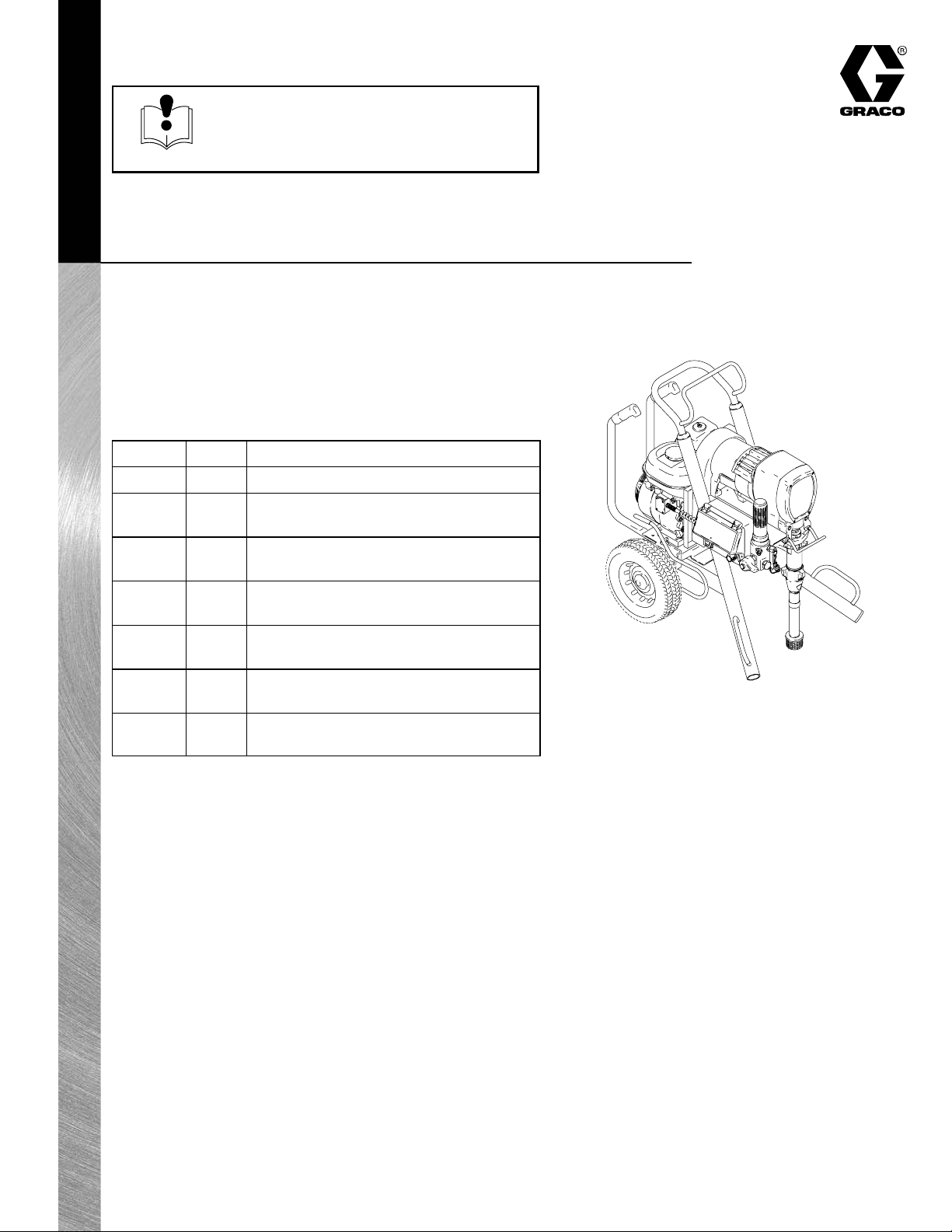
Component Identification and Function
Engine On/Off Switch
Engine Controls
Pump On/Off Switch
Pressure Control
Prime/Drain Valve
Spray Gun Trigger Lock
Reference your Spray Gun Manual
ti1852a
Motor On/Off Switch
ti1854a
5309411
Maintenance
WARNING
INJECTION HAZARD
System pressure must be manually
relieved to prevent system from starting
or spraying accidentally. Fluid under high
pressure can be injected through skin and cause
serious injury. To reduce risk of injury from injection, splashing fluid, or moving parts, follow Pres-
sure Relief Procedure whenever you:
are instructed to relieve pressure,
stop spraying,
check or service any system equipment,
or install or clean spray tip.
Pressure Relief Procedure
1. Lock gun safety latch.
2. Turn engine or electric motor ON/OFF switch to
OFF.
3. Unplug power supply cord (electric motor).
4. Move pressure control switch to OFF and turn
pressure control knob fully counterclockwise.
CAUTION
For detailed engine maintenance and specifications,
refer to separate engine manual, supplied.
DAILY: Check engine oil level and fill as necessary.
Manual 309410.
DAILY: Check that V-belt (60) is centered on pulleys
and is not inverted. Replace if worn or damaged.
DAILY: Check and fill gas tank.
DAILY: Check hoses for wear and damage.
DAILY: Check gun safety for proper operation.
DAILY: Check pressure drain valve for proper opera-
tion.
AFTER THE FIRST 20 HOURS OF OPERATION
AND EACH 100 HOURS THEREAFTER: Change
engine oil.
DAILY: Keep TSL in packing nut to help lubricate
pump packings. One full squirt of TSL is usually
enough.
5. Rotate RAC 5 tip, if used, to reverse position.
6. Unlock gun safety latch. Hold metal part of gun
firmly to grounded metal pail. Trigger gun to relieve
pressure.
7. Lock gun safety latch.
8. Open pressure drain valve. Leave pressure drain
valve open until ready to spray again.
If suspected that spray tip or hose is completely
clogged, or that pressure has not been fully relieved
after following steps above, VERY SLOWLY loosen tip
guard retaining nut or hose end coupling to relieve
pressure gradually, then loosen completely. Now clear
tip or hose obstruction.
WEEKLY: Remove cover of air filter (C) and clean
element. Replace element, if necessary. If operating in
an unusually dusty environment, check filter daily and
replace it, if necessary.
Repack connecting rod (22) top needle bearing after
every pump change.
Replacement elements can be purchased from your
local HONDA dealer.
SPARK PLUG: Use only an BPR6ES (NGK) or
W20EPR–U (NIPPONDENSO) plug. Gap plug to
0.028 to 0.031 in. (0.7 to 0.8 mm). Use a spark plug
wrench when installing and removing plug.
6 309411
Troubleshooting
Relieve pressure; page 6.
PROBLEM CAUSE SOLUTION
E=XX is displayed Fault condition exists Determine fault correction from table, page 14.
Engine won’t start Engine switch is OFF Turn engine switch on.
Engine is out of gas Refill gas tank. Honda Engines Owner’s Manual.
Engine oil level low Try to start engine. Replenish oil, if necessary.
Honda Engines Owner’s Manual.
False tripping of WatchDog
system. EMPTY is displayed. Pump does not run.
Engine operates, but displacement pump doesn’t
’
Spark plug cable disconnected or
spark plug damaged
Oil seepage into combustion
chamber
Operating conditions out of WatchDog
parameters
Low pump output; page 8.
Pressure control switch turned OFF Turn on.
Pressure setting too low Increase pressure.
Displacement pump outlet filter dirty Clean filter.
Tip or tip filter clogged Clean tip or tip filter.
Broken drive belt Replace belt.
Displacement pump rod seized by
dry paint
Connecting rod worn or damaged Replace. See page 9.
Drive housing worn or damaged Replace. See page 10.
Electrical power is not energizing clutch field Check wiring connections. Page 23.
Connect spark plug cable or replace spark plug.
Remove spark plug. Pull starter rope 3 or 4 times.
Clean or replace spark plug. Try to start engine.
Keep sprayer upright to avoid oil seepage.
Turn pressure down. Contact Graco Technical Service to adjust WatchDog parameters.
Operate without WatchDog active; Manual 309410.
Service pump. See page 16.
Reference pressure control repair. Page 14.
Reference wiring diagram. Page 23.
With pump switch ON and pressure turned to
MAXIMUM, use a test light to check for power between clutch test points on control board.
Remove 7–pin connector from control board and
measure resistance across clutch coil. At 70 F,
the resistance must be 1.7
pinion housing.
Have pressure control checked by authorized Graco dealer.
±0.2Ω; if not, replace
Clutch is worn, damaged, or incorrectly
positioned
Pinion assembly is worn or damaged Repair or replace pinion assembly. Page 11.
Replace clutch. Page 11.
7309411

PROBLEM CAUSE SOLUTION
load
Pump output low
Excessive paint leakage into
throat packing nut
Strainer (31) clogged Clean.
Piston ball (25) not seating Service piston ball check. Manual 309277.
Piston packings worn or damaged Replace packings. Manual 309277.
Displacement pump o-ring (227) is damaged Replace o-ring. Manual 309277.
Intake valve ball not seating properly Clean and service. Manual 309277.
Engine speed is too low Increase throttle setting. See Manual 309410.
V–belt slipping Tighten V–belt with tension bar (101). Adjust
bracket until it takes 15 lb of force to lock
tension bar down.
Clutch worn or damaged Replace. See page 11.
Pressure setting is too low Increase pressure. Manual 309410.
Fluid filter (318), tip filter or tip is clogged or
dirty
Large pressure drop in hose with heavy
materials
Throat packing nut is loose Remove throat packing nut spacer. Tighten
Clean filter. Manual 309410 or 309091.
Use larger diameter hose and/or reduce overall
length of hose. Use of more than 100 ft of 1/4
in. hose significantly reduces performance of
sprayer. Use 3/8 in. hose for optimum performance (50 ft minimum).
throat packing nut just enough to stop leakage.
Throat packings worn or damaged Replace packings. Manual 309277.
Displacement rod worn or damaged Replace rod. Manual 309277.
Spitting from gun Air in fluid pump or hose Check and tighten all fluid connections.
Reprime pump. Manual 309410.
Tip partially clogged Clear tip. Manual 309091.
Fluid supply is low or empty Refill and prime pump. See Startup, Manual
309410. Check fluid supply often to prevent
running pump dry.
Pump is difficult to prime Air leak Check and tighten all fluid connections.
Reduce engine speed and cycle pump as
slowly as possible during priming.
Intake valve is leaking Shut off pump and relieve pressure. Disas-
semble and clean intake valve. Be sure ball
seat is not nicked or worn and that ball seats
well. Reassemble.
Worn packings Repack pump. Manual 309277.
Fluid is too thick Thin fluid according to supplier’s recommenda-
tions.
Engine speed is too high Decrease throttle setting before priming pump.
Manual 309410.
Clutch squeaks each time
clutch engages
High engine speed at no
Gallon counter not working Bad sensor, broken or disconnected wire Check connections. Replace sensor or wire.
No display, sprayer operates Display damaged or has bad connection Check connections. Replace display.
8 309411
Clutch surfaces are not matched to each other
when new and may cause noise
Misadjusted throttle setting Reset throttle to 3700 engine rpm at no load
Worn engine governor Replace or service engine governor
Clutch surfaces need to wear into each other.
Noise will dissipate after a day of run time
 Loading...