

Page 1
INSTRUCTIONS-PARTS LIST
308398
This manual contains important
warnings and information.
READ AND KEEP FOR REFERENCE.
INSTRUCTIONS
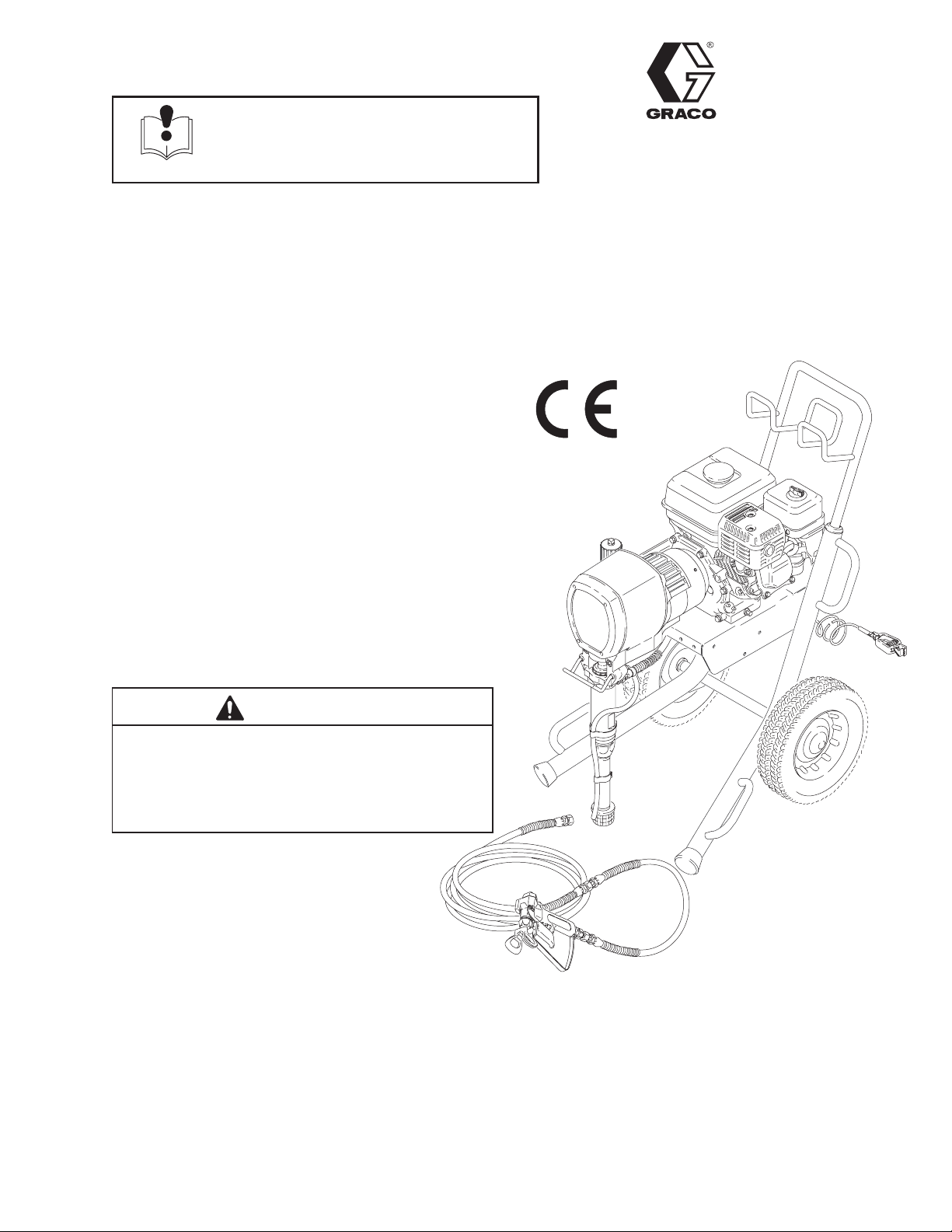
5.5 HORSEPOWER, GASOLINE–POWERED
GM7000 Airless Paint Sprayer
3000 psi (207 bar, 21 MPa) Maximum Working Pressure
Model 231326, Series D
This is a basic sprayer without a hose or a gun.
Model 231327
This is a complete sprayer with hoses and a
Contractor gun, a RAC IVt DripLesst Tip Guard,
and a 517 size SwitchTipt
Model 231800, Series B
This is a Lo-Boy sprayer without a hose or a gun.
Rev. P
Model 231382
This is a complete sprayer with hoses and a
Contractor gun, a RAC IVt DripLesst Tip Guard,
and a 517 size SwitchTipt
CAUTION
Always use a minimum hose length of 100 foot
(30.4 m) 1/4 inch ID or 50 foot (15.2 m) 3/8 inch ID.
An undersized hose may result in poor equipment
performance and damage to the clutch or pressure
control.
03466B
Model 231327 Shown
GRACO INC. P.O. BOX 1441 MINNEAPOLIS, MN 55440–1441
ECOPYRIGHT 1994, GRACO INC.
Graco Inc. is registered to I.S. EN ISO 9001
Page 2
Table of Contents
Warnings 2. . . . . . . . . . . . . . . . . . . . . . . . . . . . . . . . . . . . .
Component Identification and Function 5. . . . . . . . .
Setup 6. . . . . . . . . . . . . . . . . . . . . . . . . . . . . . . . . . . . . . . .
Fueling 8. . . . . . . . . . . . . . . . . . . . . . . . . . . . . . . . . . . . . . .
Startup 8. . . . . . . . . . . . . . . . . . . . . . . . . . . . . . . . . . . . . . .
Maintenance 10. . . . . . . . . . . . . . . . . . . . . . . . . . . . . . . . .
Flushing 11. . . . . . . . . . . . . . . . . . . . . . . . . . . . . . . . . . . . .
Suction Tube Storage 12. . . . . . . . . . . . . . . . . . . . . . . .
Troubleshooting Guide 13. . . . . . . . . . . . . . . . . . . . . . .
Repair
Bearing Housing & Connecting Rod 15. . . . . . . . . . . .
Drive Housing 16. . . . . . . . . . . . . . . . . . . . . . . . . . . . . . .
Pinion, Clutch, Clamp, Field, & Engine 18. . . . . . . . .
Pinion Housing 19. . . . . . . . . . . . . . . . . . . . . . . . . . . . . .
Clutch 20. . . . . . . . . . . . . . . . . . . . . . . . . . . . . . . . . . . . .
Field & Wiring Harness 21. . . . . . . . . . . . . . . . . . . . . . .
Clamp 21. . . . . . . . . . . . . . . . . . . . . . . . . . . . . . . . . . . . .
Symbols
Warning Symbol
WARNING
This symbol alerts you to the possibility of serious
injury or death if you do not follow the instructions.
Clutch Housing 22. . . . . . . . . . . . . . . . . . . . . . . . . . . . . .
Engine 23. . . . . . . . . . . . . . . . . . . . . . . . . . . . . . . . . . . . .
Reassembly 24. . . . . . . . . . . . . . . . . . . . . . . . . . . . . . . .
Pressure Control Replacement 26. . . . . . . . . . . . . . . .
Removing and Installing Pump 27. . . . . . . . . . . . . . . .
Displacement Pump 27. . . . . . . . . . . . . . . . . . . . . . . . .
Parts Lists and Drawings
Model 231326, Basic Sprayer 28. . . . . . . . . . . . . . . . .
Model 231800, Lo-Boy Sprayer 30. . . . . . . . . . . . . . . .
Models 231327 & 231382, Complete Sprayer 34. . .
Pinion Assembly 34. . . . . . . . . . . . . . . . . . . . . . . . . . . .
Pressure Control 35. . . . . . . . . . . . . . . . . . . . . . . . . . . .
Dimensions 35. . . . . . . . . . . . . . . . . . . . . . . . . . . . . . . . . .
Graco Phone Number 35. . . . . . . . . . . . . . . . . . . . . . . .
Technical Data 36. . . . . . . . . . . . . . . . . . . . . . . . . . . . . . .
Graco Warranty 36. . . . . . . . . . . . . . . . . . . . . . . . . . . . . .
Caution Symbol
CAUTION
This symbol alerts you to the possibility of damage to
equipment if the you do not follow the instructions.
INSTRUCTIONS
WARNING
EQUIPMENT MISUSE HAZARD
Equipment misuse can cause the equipment to rupture or malfunction and result in serious injury.
D This equipment is for professional use only.
D Read all instruction manuals, tags, and labels before operating the equipment.
D Use the equipment only for its intended purpose. If you are not sure, call your Graco distributor.
D Do not alter or modify this equipment. Use only genuine Graco parts
D Check equipment daily. Repair or replace worn or damaged parts immediately.
D Do not exceed the maximum working pressure of the lowest rated system component. Refer to the
Technical Data on page 36 for the maximum working pressure of this equipment.
D Use fluids and solvents compatible with the equipment wetted parts. Refer to the Technical Data
section of all equipment manuals. Read the fluid and solvent manufacturer’s warnings.
D Do not use hoses to pull equipment.
D Route hoses away from traffic areas, sharp edges, moving parts, and hot surfaces. Do not expose
Graco hoses to temperatures above 82_C (180_F) or below –40_C (–40_F).
D Do not lift pressurized equipment.
D Comply with all applicable local, state, and national fire, electrical, and safety regulations.
D Wear hearing protection when operating this equipment.
D Do not use 1,1,1–trichloroethane, methylene chloride, other halogenated hydrocarbon solvents or
fluids containing such solvents in pressurized aluminum equipment. Such use could result in a
chemical reaction, with the possibility of explosion.
3083982
Page 3
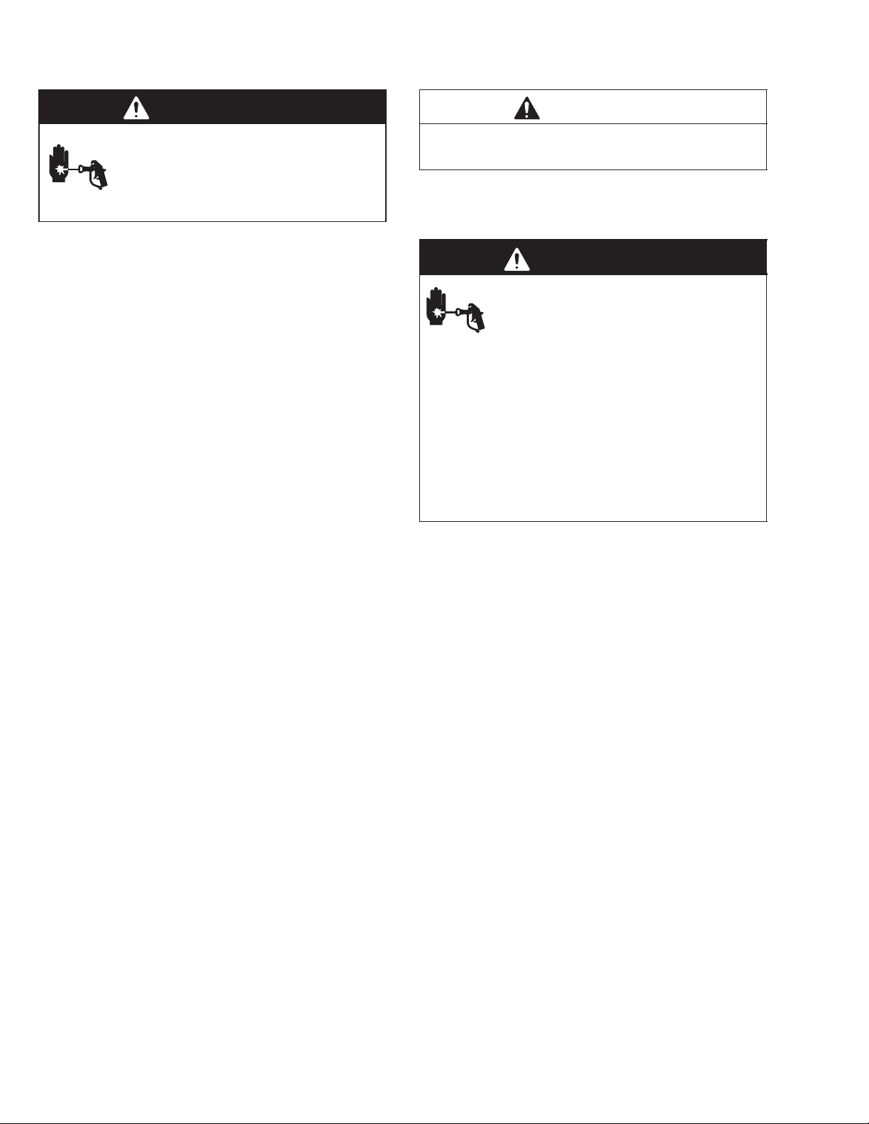
WARNING
INJECTION HAZARD
Spray from the gun, leaks or ruptured components can inject fluid into your body and cause extremely
serious injury, including the need for amputation. Fluid splashed in the eyes or on the skin can also
cause serious injury.
D Fluid injected into the skin may look like just a cut, but it is a serious injury. Get immediate medi-
cal attention.
D Do not point the gun at anyone or at any part of the body.
D Do not put your hand or fingers over the spray tip.
D Do not stop or deflect leaks with your hand, body, glove or rag.
D Do not “blow back” fluid; this is not an air spray system.
D Always have the tip guard and the trigger guard on the gun when spraying.
D Check the gun diffuser operation weekly. Refer to the gun manual.
D Be sure the gun trigger safety operates before spraying.
D Lock the gun trigger safety when you stop spraying.
D Follow the Pressure Relief Procedure on page 10 if the spray tip clogs and before cleaning,
checking or servicing the equipment.
D Tighten all fluid connections before operating the equipment.
D Check the hoses, tubes, and couplings daily. Replace worn or damaged parts immediately. Do not
repair high pressure couplings; you must replace the entire hose.
D Fluid hoses must have spring guards on both ends, to help protect them from rupture caused by
kinks or bends near the couplings.
TOXIC FLUID HAZARD
Hazardous fluid or toxic fumes can cause serious injury or death if splashed in the eyes or on the skin,
inhaled, or swallowed.
D Know the specific hazards of the fluid you are using.
D Store hazardous fluid in an approved container. Dispose of hazardous fluid according to all local,
state and national guidelines.
D Always wear protective eyewear, gloves, clothing and respirator as recommended by the fluid and
solvent manufacturer.
FUEL HAZARD
The fuel used in this unit is combustible and when spilled on a hot surface can ignite and cause a fire.
D Do not fill the fuel tank while the engine is running or hot.
EXHAUST HAZARD
The exhaust contains poisonous carbon monoxide which is colorless and odorless.
D Do not operate this equipment in a closed building.
308398 3
Page 4
WARNING
FIRE AND EXPLOSION HAZARD
Improper grounding, poor ventilation, open flames or sparks can cause a hazardous condition and result in a fire or explosion and serious injury.
D If there is any static sparking or you feel an electric shock while using this equipment, stop spray-
ing immediately. Do not use the equipment until you identify and correct the problem.
D Provide fresh air ventilation to avoid the buildup of flammable fumes from solvents or the fluid
being sprayed.
D Keep the spray area free of debris, including solvent, rags, and gasoline.
D Disconnect all electrical equipment in the spray area.
D Extinguish all open flames or pilot lights in the spray area.
D Do not smoke in the spray area.
D Do not turn on or off any light switch in the spray area while operating or if fumes are present.
D Do not operate a gasoline engine in the spray area.
D Ground the sprayer to a true earth ground with the ground wire and clamp (supplied).
D Use only electrically conductive hoses.
MOVING PARTS HAZARD
Moving parts can pinch or amputate your fingers.
D Keep clear of all moving parts when starting or operating the pump.
D Before servicing the equipment, follow the Pressure Relief Procedure on page 10 to prevent the
equipment from starting unexpectedly.
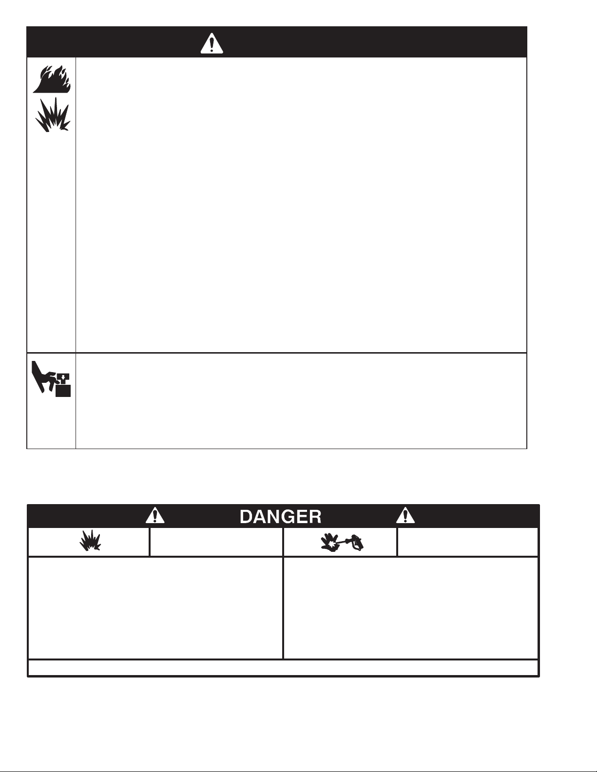
NOTE: This is an example of the DANGER label on your sprayer. This label is available in other languages, free of
charge. See page 33 to order.
FIRE AND
EXPLOSION HAZARD
Spray painting, flushing or cleaning equipment with flammable liquids in confined areas can result in fire or explosion.
Use outdoors or in extremely well ventilated areas. Ground equipment, hoses, containers and objects being sprayed.
Avoid all ignition sources such as static electricity from plastic drop
cloths, open flames such as pilot lights, hot objects such as cigarettes, arcs from connecting or disconnecting power cords or turning light switches on and off.
Failure to follow this warning can result in death or serious injury.
Liquids can be injected into the body by high pressure airless spray
or leaks – especially hose leaks.
Keep body clear of the nozzle. Never stop leaks with any part of the
body. Drain all pressure before removing parts.Avoid accidental triggering of gun by always setting safety latch when not spraying.
Never spray without a tip guard.
In case of accidental skin injection, seek immediate
“Surgical Treatment”.
Failure to follow this warning can result in amputation or serious
injury.
SKIN INJECTION
HAZARD
READ AND UNDERSTAND ALL LABELS AND INSTRUCTION MANUALS BEFORE USE
3083984
Page 5
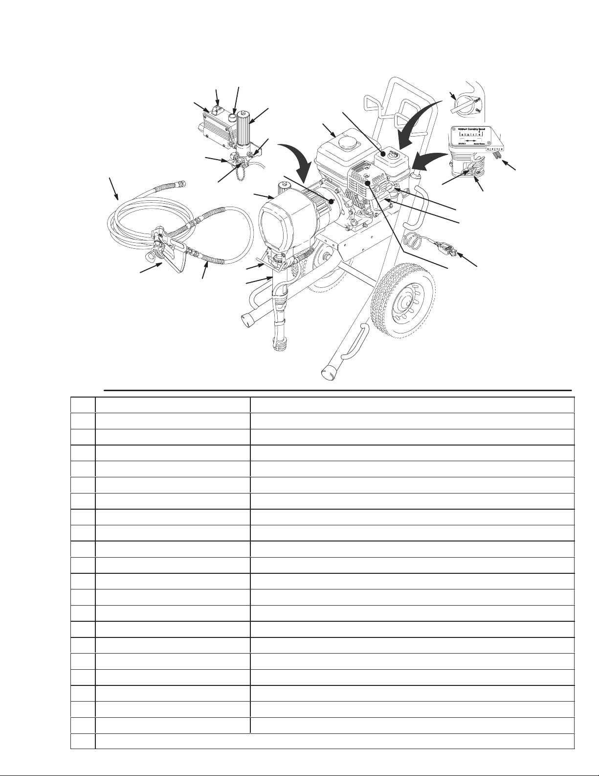
Component Identification and Function
B
M
53
A
51
N
C
D
K
202
L
20
204
203
202 Main hose
203 Whip end hose
204 Contractor gun with RAC IV
DripLess tip guard and 517 size SwitchTip
Fig. 1
A Pressure Control Switch ON/OFF, enables/disables clutch function
B Pressure Adjusting Knob Controls fluid outlet pressure
C Air Cleaner* Filters air entering the carburetor
D Fuel Tank* Holds 0.95 gallons (3.6 liter) of [(R+M)/2]; 86 octane gasoline
E Muffler* Reduces noise of internal combustion
F Spark Plug Cable* Routes electrical current to spark plug
G Fuel Shutoff Lever* On/off lever to regulate fuel flow from gasoline tank to carburetor
H Choke* Enriches air/gasoline mixture for cold starting
J Throttle* Adjusts engine speed for large or small orifice spray tips
K Engine Switch* Enables/disables engine operation
L Secondary Fluid Outlet Second hose and spray gun is connected here
M Pressure Control Controls clutch cycling to maintain fluid pressure.
N Primary Fluid Outlet Hose and spray gun is connected here
1 Engine* 5.5 HP gasoline engine
4 Clutch Housing Transfers power from engine to drive assembly
20 Drive Assembly Transfers power from clutch to displacement pumps
28 Displacement Pump Provides fluid to be sprayed through spray gun
51 Fluid Filter Filters fluid between source and spray gun
47 Grounding Clamp and Wire Grounds sprayer system
53 Pressure Drain Valve Relieves fluid pressure when open
71 Pail Hanger Provides a hanger for paint pail
* For more detailed explanations of these controls, refer to the Honda engine manual; supplied
71
28
4
H
G
F
1
E
Model 231327 shown
47
308398 5
J
03467C
Page 6
Setup
NOTE: A 55 gallon (200 liter) suction tube kit, Part No.
236951, is available.
WARNING
If you are supplying your own hoses and spray
gun, be sure the hoses are electrically conductive,
that the gun has a tip guard, and that each part is
rated for at least 3000 psi (207 bar, 21 MPa) Maxi-
mum Working Pressure. This is to reduce the risk
of serious injury caused by static sparking, fluid
injection or over-pressurization and rupture of the
hose or gun.
CAUTION
To avoid damaging the pressure control, which may
result in poor equipment performance and component damage, follow these precautions.
1. Always use nylon spray hose. Never use a wire
braid hose; it is too rigid to act as a pulsation
dampener.
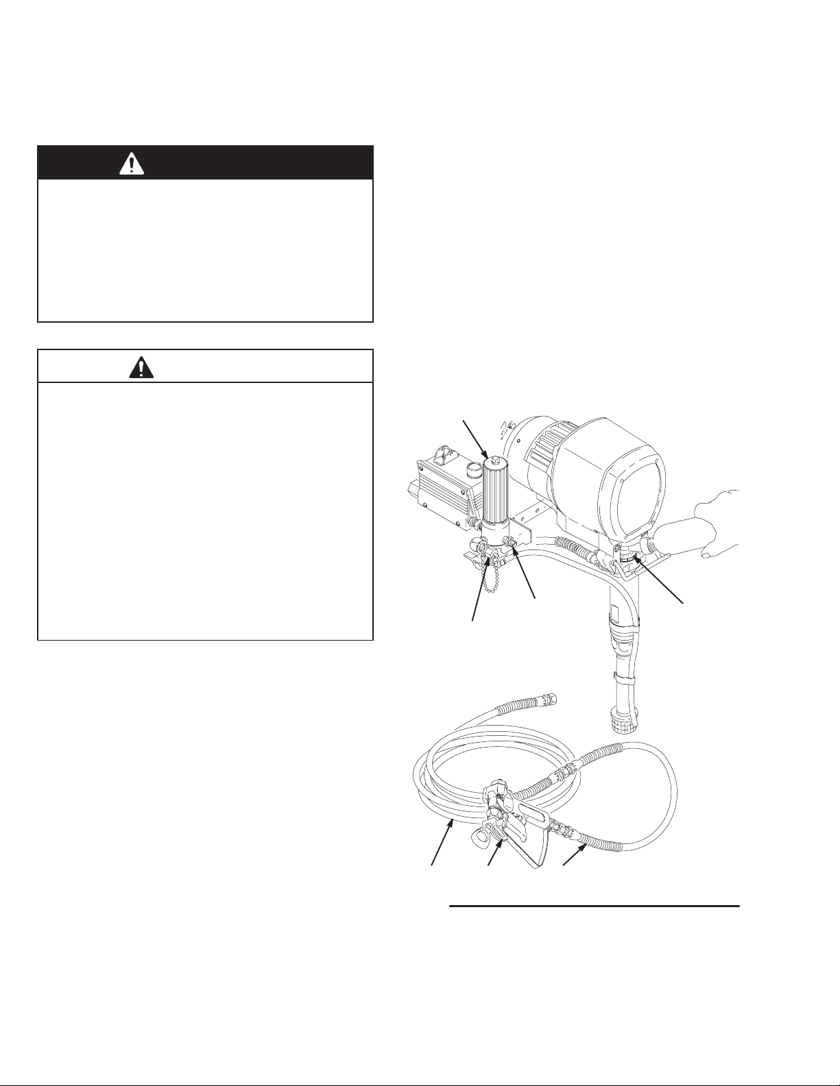
2. Two gun hookup. Remove the cap (56) from the
secondary hose outlet. Connect the second outlet
hoses to the sprayer as explained in Step 1,
above.
3. Fill packing nut/wetcup. Fill the packing nut/wetcup (416) 1/3 full with Graco Throat Seal Liquid
(TSL), supplied. See Fig. 2.
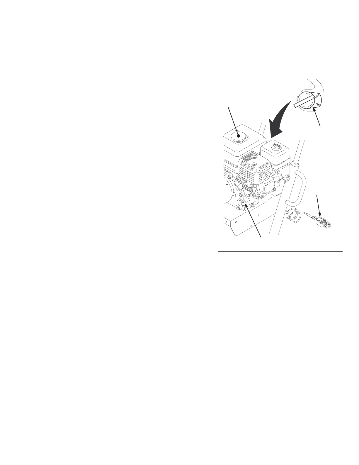
4. Check the engine oil level. Refer to the Honda
engine manual, supplied. This is a summary of the
information: Remove one of the oil fill plugs (P);
the oil should be almost overflowing. See Fig. 3.
Add oil as necessary.
Recommended lubrication oil: Use a high–quality,
detergent oil, SAE 10W–40, classified “FOR
SERVICE SE or SF”, for regular use and for
breaking–in a new engine.
51
2. Always use a minimum hose length of 50 foot
(15.2 m) x 3/8 inch ID hose at each outlet.
3. Never install any shutoff device between the filter
(51) and main hose (202). See Fig. 2.
4. Always use the main filter outlet (60) for a one
gun operation. Never plug this outlet.
1. Connect hose and gun. (Refer to Fig. 2.)
a. Remove the plastic cap from the 3/8 npsm (m)
filter outlet nipple (60). Screw the 50 foot (15.2
m) main fluid hose (202) onto the nipple. Read
the CAUTION, above.
b. Connect the whip end hose (203) between the
main fluid hose and the inlet adapter of the
gun (204).
c. DO NOT use thread sealant, and DO NOT
install the spray tip yet!
60
56
202 204 203
Fig. 2
416
Model 231327 shown
03469A
3083986
Page 7
Setup
5. Be sure your system is properly grounded
before operating it. Read and follow the warning
section, FIRE OR EXPLOSION HAZARD, on page
4. Use the grounding wire and clamp (47) whenever the sprayer is used as a stationary unit.
6. Fill the gas tank. See Fueling, page 8.
7. Flush the pump to remove the lightweight oil
which was left in the pump to protect it from rust.
a. Before using water–base paint, flush with
mineral spirits, followed by soapy water, and
then flush with clean water.
b. Before using oil–base paint, flush with mineral
spirits, only.
c. See Flushing on page 11 for the flushing
procedure.
8. Prepare the paint according to the manufacturer’s
recommendations.
a. Remove any skin that may have formed.
9. Keep the sprayer upright and level during
operation and whenever it is being moved. See the
last CAUTION on page 9.
L
K
47
b. Stir the paint to mix the pigments.
c. Strain the paint through a fine nylon mesh bag
(available at most paint dealers) to remove the
particles that could clog the filter or spray tip.
This is probably the most important step
toward trouble–free spraying.
Fig. 3
P
03470A
308398 7
Page 8
Fueling
WARNING
Gasoline is extremely flammable and explosive
under certain conditions.
Always turn the engine switch (K) to off before
refueling.
Refuel in a well–ventilated area.
Do not smoke or allow flames or sparks in the area
where the engine is refueled or where the gasoline
is stored.
Do not overfill the tank. Make sure the gas fill cap
(L) is securely closed after refueling.
Be careful not to spill fuel when fueling. Fuel vapor
or spilled fuel can ignite. If any fuel is spilled, make
sure the area is dry before starting the engine.
1. Fuel specifications. Use automotive gasoline
with a pump octane number [(R + M)/2] of 86 or
higher, or a research octane number of 91 or
higher. Unleaded fuel minimizes the combustion
chamber deposits.
2. Gasolines containing alcohol (gasohol). Do not
use gasohol which contains methanol, if the gasohol does not contain cosolvents and corrosion
inhibitors for methanol. Even if it does contain such
additives, do not use the gasohol if it contains
more than 5% methanol.
NOTE: The HONDA engine warranty does not cover
the damage resulting from the use of gasolines containing alcohol. See the HONDA engine manual for
more information.
3. General. Do not use any oil and gasoline mixtures
or contaminated gasoline. Avoid getting any dirt,
dust or water in the fuel tank.
4. Tank Capacity. 0.95 gallons (3.6 liter). Always
leave at least 1/2 in. at the top of the tank for
expansion.
5. Shut off the engine before refueling.
6. After refueling, tighten the fuel tank cap firmly.
Startup
Before You Start the Sprayer
1. See Flushing on page 11 to determine if you
should flush the sprayer.
2. Be sure the gas tank is full.
3. Check the engine oil level.
NOTE: The engine stops automatically, or will not
start, if it is low on oil. Refer to the oil fill procedure in
the Honda engine manual or to step 4, page 6.
4. Be sure the spark plug cable is firmly pushed
onto the plug.
Starting the Sprayer
NOTE: Refer to Fig. 1 as you start the sprayer.
1. When starting a sprayer that IS NOT PRIMED,
remove the spray tip.
2. If a secondary hose and gun is not installed,
be sure the cap is securely plugging the secondary
outlet fitting.
3. Place the suction tube into the paint, water or
solvent container, depending on whether you are
flushing or are ready to spray.
3083988
4. Open the black fuel shutoff lever by pushing it in
the direction of the arrow.
CAUTION
Never try to start the engine unless fluid pressure is
relieved and the pressure control switch is OFF.
Trying to start the engine when it is pressurized
could damage the recoil system.
5. Turn the pressure control switch to OFF.
6. To start the engine:
a. Turn the pressure adjusting knob all the way
counterclockwise to the lowest pressure setting.
b. Slide the metal throttle lever away from the
fuel tank to maximum position (fully left).
c. If the engine is cold, close the choke by mov-
ing the gray lever.
d. If the engine is warm, close the choke by
moving the gray lever only half way or not at
all.
e. Turn the engine switch to ON.
Page 9
Startup
WARNING
A rope which recoils too quickly may hit someone
and cause serious injury. The rope could also jam
in recoil assembly.
f. Hold the frame of the sprayer with one hand
and pull the starter rope rapidly and firmly.
Continue holding the rope as you let it return.
Pull and return the rope until the engine starts.
g. Open the choke as soon as the engine starts,
except in cold weather. In cold weather, leave
the choke closed for 10 to 30 seconds before
opening it to keep the engine running.
7. Unlock the gun trigger safety.
8. To start the pump:
a. Open the pressure drain valve.
b. Turn the pressure control switch to ON.
c. Turn the pressure control knob about 1/4 turn
from minimum pressure. Run the pump until
fluid is flowing smoothly from the pressure
drain valve, indicating the pump is fully primed.
d. Close the pressure drain valve. Hold a metal
part of the gun firmly against a grounded metal
pail and squeeze the trigger until fluid flows
from the gun.
WARNING
To reduce the risk of serious injury from fluid injection, NEVER operate the spray gun with the tip
guard removed.
10. Install the spray tip in the gun. See the separate
tip instruction manual, 308644, supplied.
11. Adjust the engine speed and pump pressure.
Unlock the gun trigger safety. Trigger the gun onto
a test paper to check the spray pattern and atomization. Turn the pressure adjusting knob until you
get a good pattern. Then slowly lower the throttle
setting as far as you can without changing the
spray pattern.
CAUTION
Always use the lowest needed fluid pressure and the
lowest needed throttle setting, to increase the life of
the sprayer. Higher settings cause excessive clutch
cycling, premature tip wear and premature pump
wear.
e. Release the trigger. Lock the gun trigger
safety.
9. If you have not primed the sprayer with paint
yet, move the suction tube to the paint container.
Unlock the gun trigger safety. Trigger the gun into
the water/solvent pail just until paint appears.
Release the trigger and lock the trigger safety.
Repeat for the second gun if two guns are used.
CAUTION
Close the black fuel shutoff lever whenever you are
transporting the sprayer to prevent fuel from flooding
the engine.
Keep the sprayer upright and level when operating it
and when transporting it. This prevents crankcase oil
from leaking into the combustion chamber, which
makes startup very difficult.
308398 9
Page 10
Maintenance
WARNING
INJECTION HAZARD
To reduce the risk of serious injury,
whenever you are instructed to relieve
pressure, follow the Pressure Relief
Procedure on page 10.
DAILY: Check the engine oil level and fill as neces-
sary.
DAILY: Check hose for wear and damage.
DAILY: Check gun safety for proper operation.
DAILY: Check pressure drain valve for proper opera-
tion.
DAILY: Check and fill the gas tank.
AFTER THE FIRST 20 HOURS OF OPERATION
Drain the oil and refill with clean oil.
CAUTION
For detailed engine maintenance and specifications,
refer to the separate engine manual, supplied.
WARNING
INJECTION HAZARD
The system pressure must be manually
relieved to prevent the system from
starting or spraying accidentally. Fluid
under high pressure can be injected through the
skin and cause serious injury. To reduce the risk of
an injury from injection, splashing fluid, or moving
parts, follow the Pressure Relief Procedure
whenever you:
D are instructed to relieve the pressure,
D stop spraying,
D check or service any of the system equipment,
D or install or clean the spray tip.
WEEKLY: Remove the cover of the air filter and
clean the element. Replace the element, if necessary.
If operating in an unusually dusty environment, check
the filter daily and replace it, if necessary.
Replacement elements can be purchased from your
local HONDA dealer.
WEEKLY: Check the level of the TSL in the displacement pump packing nut. Fill the nut, if necessary. Keep
TSL in the nut to help prevent fluid buildup on the
piston rod and premature wear of the packings.
AFTER EACH 100 HOURS OF OPERATION:
Change the oil.
MONTHLY: Oil connecting rod.
SPARK PLUG: Use only an (NGK) BPR6ES or
W20 EPR-U (NIPPON DENSO) plug. Gap the plug to
0.028 to 0.031 inch (0.7 to 0.8 mm). Use a spark plug
wrench when installing and removing the plug.
Pressure Relief Procedure
1. Lock the gun trigger safety.
2. Turn the engine switch to OFF.
3. Move the pressure control switch to OFF.
4. Unlock the trigger safety. Hold a metal part of the
gun firmly to the side of a grounded metal pail, and
trigger the gun to relieve the pressure.
See Fig. 4, A.
5. Lock the gun trigger safety.
6. Open the pressure drain valve. Leave the valve
open until you are ready to spray again.
7. Disconnect the spark plug cable.
If you suspect that the spray tip or hose is completely
clogged, or that pressure has not been fully relieved
after following the steps above, VERY SLOWLY
loosen the tip guard retaining nut or hose end coupling
to relieve the pressure gradually, then loosen completely. Now clear the tip or hose.
30839810
Page 11
Flushing
When to Flush
1. New Sprayer. This sprayer was factory tested in
lightweight oil,which was left in to protect the pump
parts.
Before using water–base paint, flush with mineral
spirits, followed by a soapy water flush, and then a
clean water flush.
Before using oil–base paint, flush with mineral
spirits.
2. Changing Colors. Flush with a compatible solvent
such as mineral spirits or water.
3. Changing from water–base to oil–base paint. Flush
with warm, soapy water, then mineral spirits.
4. Changing from oil–base to water–base paint. Flush
with mineral spirits, followed by warm, soapy
water, and then a clean water flush.
CAUTION
When using oil–based paint, flush out the mineral
spirits with the paint to be sprayed.
How to Flush
WARNING
INJECTION HAZARD
To reduce the risk of serious injury,
whenever you are instructed to relieve
pressure, follow the Pressure Relief
Procedure on page 10.
NOTE: The word solvent refers to water or oil-based
solvent.
1. Relieve pressure.
2. Remove the filter bowl (A) and screen (B); see
instruction manual 307273, supplied. Install the
bowl and support (C), without the screen, to flush.
Clean the screen separately. See Fig. 5.
To prevent pump corrosion, never leave water or
any type of paint in the sprayer when it is not in use.
Pump the water or the paint out with mineral spirits.
5. Storage.
Water base paint: flush with water, then mineral
spirits and leave the pump, hose and gun filled
with mineral spirits. Shut off the sprayer, remove
the spark plug cable, and open the pressure drain
valve to Relieve the pressure. Leave the drain
valve open.
Oil base paint: flush with mineral spirits and leave
the pump, hose and gun filled with mineral spirits.
Shut off the sprayer, remove the spark plug cable,
and open the pressure drain valve to relieve the
pressure. Leave the drain valve open.
6. Startup after storage.
Before using water–base paint, flush out the
mineral spirits with soapy water, and then with
clean water.
3. Close the pressure drain valve.
4. Put the suction tube in a grounded pail of solvent.
5. Remove the spray tip from the gun(s).
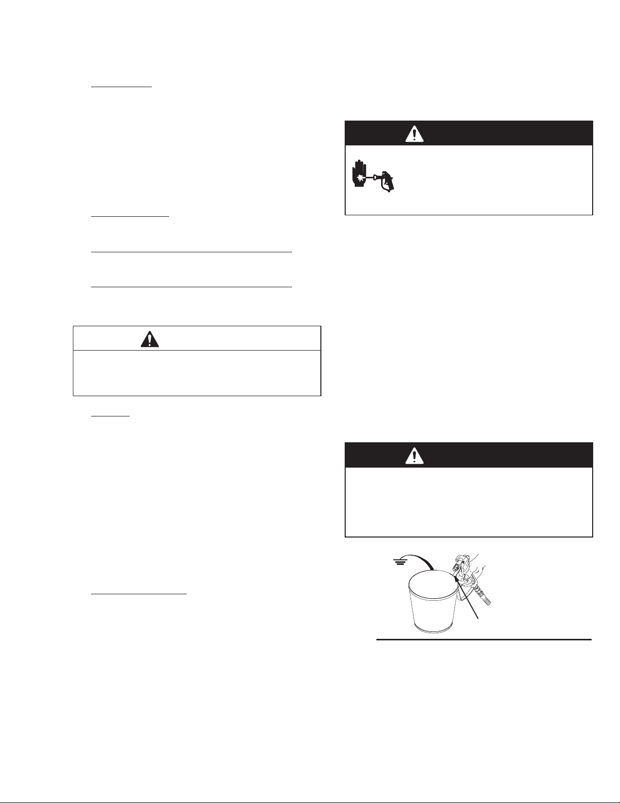
WARNING
To reduce the risk of static sparking and splashing
when flushing, always remove the spray tip from
the gun, and hold a metal part of the gun firmly to
the side of, and aimed into, a grounded metal pail.
See Ref. A in Fig. 4.
A
Fig. 4
01024
308398 11
Page 12

Flushing
6. Follow Startup on page 8. Keep the gun triggered until clean solvent comes from the nozzle.
Release the trigger and lock the gun trigger safety.
NOTE: For two guns, unlock the gun trigger safety on
the second gun and trigger that gun until clean solvent
comes from the nozzle. Flush the first gun and then
the second gun at least one more time.
7. Check all fluid connections for leaks. Relieve the
pressure before tightening any connections. Start
the sprayer. Recheck the connections for leaks.
8. Remove the suction tube from the solvent pail.
Unlock the gun trigger safety. Trigger the gun to
force solvent from the hose. Do not let the pump
run dry for more than 30 seconds, to avoid damaging the pump packings. Relieve the pressure.
9. Remove the strainer, suction tube and suction
hose and clean them separately to be sure all
paint sediment is removed. Dried paint can build
up in these parts and later cause performance
problems.
10. Unscrew the filter bowl and reinstall the clean
screen. Reinstall the bowl, hand tight only.
11. Follow Storage or Changing Colors, to the left.
Relieve the pressure.
Fig. 5
B
C
53
Model 231326 shown 06878
A
Suction Tube Storage
Place the suction tube in the receptacle on the cart
frame as shown in Fig. 6.
Fig. 6
06970
30839812
Page 13

Troubleshooting
displ
t
WARNING
INJECTION HAZARD
To reduce the risk of serious injury,
including fluid injection or splashing in
the eyes or on the skin, or injury from
moving parts, always follow the Pressure Relief
Procedure Warning, page 10, before checking,
adjusting, cleaning or shutting down the sprayer.
Disconnect the spark plug!
Check everything in the chart before disassembling the sprayer.
PROBLEM CAUSE SOLUTION
The engine or sprayer won’t
start.
The engine won’t “pull over”. There is oil seeping into the combustion
The engine operates, but the
p
acement pump does no
operate. The pressure setting is too low. Turn the pressure adjusting knob clockwise to
p
p
The engine switch is not on. Turn on the switch.
The engine is out of gas. Refill the gas tank. See page 8.
The engine oil level is low. Try to start the engine. Replenish the oil, if nec-
The spark plug cable is disconnected or it is
damaged
There is frozen water in the pressure control. Allow the sprayer to thaw completely before
chamber.
The pressure control switch is turned off. Turn on the switch.
The fluid filter (51) is dirty. Clean the filter. See page 12.
The tip or the tip filter is clogged. Clean the tip or the tip filter. See the gun
The displacement–pump rod is stuck due to
dried paint.
essary. See Step 4, page 6.
Reconnect the spark plug cable or replace the
spark plug.
starting it.
Remove the spark plug. Pull the starter rope 3
or 4 times. Clean or replace the plug. Try to
start the engine. Keep the sprayer upright to
avoid oil seepage.
increase pressure.
instruction manual.
Repair the pump. See manual 307806.
The connecting rod is worn or damaged. Replace the connecting rod. See page 15.
The drive housing is worn or damaged. Replace the drive housing. See page 16.
The electrical power is not energizing the field. Check the wiring connections. See page 23.
With the pressure control switch turned on and
the pressure turned to maximum, use a test
light to check the power at the black and white
wires from the pressure control.
Have the pressure control checked by an authorized Graco dealer.
The clutch is worn, damaged, or incorrectly
positioned.
The pinion assembly is worn or damaged. Repair or replace the pinion assembly. See
Replace the clutch. See page 20.
page 18.
308398 13
Page 14

PROBLEM CAUSE SOLUTION
th
the d
f
The pump output is low on
p
e upstroke.
The pump output is low on
ownstroke or on both o
the strokes. The piston packings are worn or damaged. Replace the packings. See manual 307806.
The paint leaks into the wetcup.
The fluid delivery is low.
The inlet screen (31 or 23a) is clogged. Clean the screen.
The piston ball (425) is not seating. Service the piston ball–check. See manual
The piston packings are worn or damaged. Replace the packings. See manual 307806.
The gasket (417) in the displacement pump is
worn or damaged.
The inlet screen (31 or 23a) is clogged. Clean the screen.
The intake valve ball is not seating
properly.
The engine speed is too low. Increase the throttle setting. See Step 11,
The clutch is worn or damaged. Replace the clutch. See page 20.
The wetcup is loose. Tighten the wetcup just enough to stop leak-
The throat packings are worn or damaged. Replace the packings. See manual 307806.
The displacement rod is worn or damaged. Replace the rod. See manual 307806.
The inlet screen is clogged. Clean the inlet screen.
307806.
Replace the gasket. See manual 307806.
Clean the intake valve. See manual 307806.
page 9.
age.
Fluid is spitting from the gun.
The pump is difficult to prime.
The pressure setting is too low. Increase the pressure. See Step 11, page 9.
The engine speed is too low. Increase the throttle setting. See Step 11,
The fluid filter (51), the tip filter or the tip is
clogged or dirty.
There is a large pressure drop in the hose with
heavy materials.
There is air in the pump or the hose. Check and tighten all the fluid connections.
The tip is partially clogged. Clear the tip. See the gun instruction manual.
The fluid supply is low or empty. Refill the fluid supply. Prime the pump. See
There is air in the pump or the hose. Check and tighten all the fluid connections.
The intake valve is leaking. Clean the intake valve. Be sure ball seat is not
page 9.
Clean the filter. See page 12. Or, see the gun
instruction manual.
Use a larger diameter hose and/or reduce the
overall length of hose. Use of more than 100 ft
of 1/4 in. hose significantly reduces the performance of the sprayer. Use 3/8 in. hose for optimum performance (50 ft minimum).
Reprime the pump. See page 13.
page 8. Check the fluid supply often to prevent running the pump dry.
Reduce the engine speed and cycle the pump
as slowly as possible during priming.
nicked or worn and that the ball seats well.
Reassemble the valve.
The pump packings are worn. Replace the pump packings. See manual
The paint is too thick. Thin the paint according to the supplier’s
The engine speed is too high. Decrease the throttle setting before priming the
30839814
307806.
recommendations.
pump. See Step 11, page 9.
Page 15

Bearing Housing & Connecting Rod
13. Align the connecting rod with the crank (A) and
WARNING
INJECTION HAZARD
To reduce the risk of serious injury,
whenever you are instructed to relieve
pressure, follow the Pressure Relief
Procedure on page 10.
carefully align the locating pins (F) in the drive
housing (20) with the holes in the bearing housing
(21). Push the bearing housing onto the drive
housing or tap it into place with a plastic mallet.
CAUTION
NOTE: Steps 1 to 13 refer to Fig. 7.
1. Relieve pressure.
2. Remove the screws (68) and the front cover (23).
3. Remove the spring clips (112, 114) and the drain
hose (113). Unscrew the suction tube (30) from the
pump, holding a wrench on the pump intake valve
(B) to keep the pump from loosening.
4. Disconnect the pump outlet hose (59) from the
displacement pump outlet nipple (87).
5. Use a screwdriver to push up the retaining spring
(26) at the top of the pump. Push the pin (25) out
the rear.
6. Loosen the jam nut (27) with an adjustable
wrench. Unscrew and remove the displacement
pump.
7. Use a hex key wrench to remove the four screws
(73) and lockwashers (74) from the bearing housing (21).
DO NOT use the bearing housing screws (73) to
align or seat the bearing housing with the drive
housing. These parts must be aligned using the
locating pins (F), to help avoid premature bearing
wear.
14. Install the screws (73) and lockwashers (74) on the
bearing housing. Tighten evenly to 40 "5 ft-lbs
(54 "7 Nm).
15. Refer to Installing the Pump on page 31.
1 Torque the screw to
40 "5 ft-lbs (54 "7 Nm).
E
D
22
C
74
1
73
20
A
8. While pulling the connecting rod (22) with one
hand, lightly tap the lower rear of the bearing
housing (21) with a plastic mallet to loosen it from
the drive housing (20). Pull the bearing housing
and the connecting rod assembly (22) off the drive
housing.
9. Inspect the crank (A) for excessive wear and
replace parts as needed.
10. Evenly lubricate the inside of the bronze bearing
(C) in the bearing housing (21), and the inside of
the connecting rod link (D), with high–quality motor
oil (do not use grease). Liberally pack the roller
bearing (E) in the connecting rod assembly (22)
with bearing grease.
11. Assemble the connecting rod (22) and bearing
housing (21).
12. Clean the mating surfaces of the bearing and drive
housings.
Fig. 7
68
112
113
114
23
27
25
F
21
26
59
87
B
30
Model 231326 Shown
03472
308398 15
Page 16

Drive Housing
WARNING
INJECTION HAZARD
To reduce the risk of serious injury,
whenever you are instructed to relieve
pressure, follow the Pressure Relief
Procedure on page 10.
NOTE: Refer to Fig. 8 for this procedure.
1. Relieve pressure.
2. Remove the bearing housing. Follow Steps 1 to 8
on page 15.
3. Remove the two screws (24) and lockwashers (29)
from the drive housing (20).
4. Remove the four screws (17) and lockwashers
(29) from the pinion housing (19).
5. Lightly tap around the drive housing (20) to loosen
the drive housing. Pull the drive housing straight
off the pinion housing. Be prepared to support the
gear cluster (18), which may also come out.
CAUTION
DO NOT drop the gear cluster (18) when removing
the drive housing (20). The gear cluster is easily
damaged. The gear may stay locked in the drive
housing or pinion housing.
DO NOT lose the thrust balls (20b or 19d) located at
each end of the gear cluster, or allow them to fall
between the gears. The ball, which is heavily covered with grease, usually stays in the shaft recesses, but could be dislodged. If the balls are
caught between the gears and not removed, they
will seriously damage the drive housing. If the balls
are not in place, the bearings will wear prematurely.
6. Liberally apply bearing grease to the gear cluster
(18). A tube of grease is supplied with each replacement gear cluster. Use a full 7 ounces (190
grams) of grease. Be sure the thrust balls (20b
and 19d) are in place.
7. Place the washer (20a) on the shaft protruding
from the large shaft of the drive housing (20). Align
the gears and push the new drive housing straight
onto the pinion housing and locating pins (B).
8. Starting at Step 4, work backwards to reassemble
the sprayer. Or, move ahead to the next section in
this manual if further service is needed.
30839816
Page 17

23
68
73
112
74
Drive Housing
20a
20
29
24
21
19
17
29
B
17
29
19d
18
20b
Fig. 8
113
114
Model 231326 Shown
03473
308398 17
Page 18

Pinion, Clutch, Clamp, Field, & Engine
Disassembling these parts can start from the pinion
housing, or from the clutch if no pinion service is
needed.
If starting from the pinion housing, first follow Steps
3 to 5 of DRIVE HOUSING, on page 16, and then
continue with the procedure below.
If starting from the clutch, see page 20.
Pinion Housing Removal
WARNING
CAUTION
Do not lose the thrust ball (19d). Refer to the CAUTION on page 16 for more information.
NOTE: To disassemble the pinion, go to page 19. To
disassemble more of the sprayer, go to page 20. To
reassemble the sprayer from this point, skip ahead to
Reassembly, page 25, step 7.
INJECTION HAZARD
To reduce the risk of serious injury,
whenever you are instructed to relieve
pressure, follow the Pressure Relief
Procedure on page 10.
NOTE: Refer to Fig. 9 for Steps 1 to 3.
1. Relieve pressure.
2. Remove the two bottom screws (10) and lockwashers (11) first, then remove the two side
screws (10) and lockwashers (11), and last remove
the top screw (10) and lockwasher (11).
3. Pull the pinion housing (19) away from the clutch
housing. The armature (4a) will come with it.
4. Pull the armature (4a) off the hub (19j) of the
pinion housing. Also see Fig. 10.
1
19
19d
Fig. 9
See page 19.
10
11
2
4a
1
03474
30839818
Page 19

Fig. 10
A
Pinion Housing
The back of the pinion housing (19a).
6
1
19k
2
1.45 in
19b
19p19n
19c3
19g**
19h**
5
19d
19e
3
19a
1
2
Slide the pinion assembly in here.
Lubricate the exterior.
3
4
Lubricate the inner and outer diameters.
5 Lubricate the teeth.
6
This is a cutaway view of the
pinion housing (19a).
19j**
19m**
4
03475A
Repairing the Pinion
NOTE: Refer to Fig. 10 except where noted.
NOTE: A hydraulic press is required if you purchase
the pinion parts individually. Otherwise, use Repair Kit
No. 240162, which includes the shaft and bearings
pre–assembled and lubricated.
If using Repair Kit 240162, follow Steps 1 to 5, below.
1. Remove the small ring (19m**) from the hub (19j)
and the large ring (19k) from the bearing recess of
the pinion housing (19a).
2. Push on the front of the shaft (19g**) to force the
bearing and hub assembly out of the housing
(19a).
3. Install the new shaft assembly into the pinion
housing; push it to the shoulder of housing (19a).
4. Install the ring (19k) and then the ring (19m**).
5. Go to Reassembly, page 25, step 7., or continue
on page 20.
A Place the steel blocks as
shown to press off the
large bearing (19h).
B Hydraulic press
C Use a round steel bar to
push on the shaft (19g)
D Position two steel bars
as shown (front bar not
shown).
E Position two steel bars
as shown.
F Platform of hydraulic
press
Fig. 11
B
F
C
19j
19h
D
E
03499
If purchasing parts separately, use these instructions.
Disassemble as far as needed for the parts being
replaced.
NOTE: The old bearing (19h) will be damaged when
removed. Have an extra bearing on hand if you need
to remove it for any reason.
1. Remove the small ring (19m) from the hub (19j).
2. Remove the snap ring (19k) from the bearing
recess of the pinion housing (19a).
3. Push on the front of the shaft (19g) to force the
bearing (19h) and hub (19j) assembly out of the
housing.
4. Using a hydraulic press, place pieces of steel
bar stock on the inner race of the large bearing
(19h) and press the shaft through the hub and
bearing. See Fig. 11.
5. Apply lubricant to the parts as shown in Fig. 10.
6. Press fit the following parts: Large bearing (19h) to
the large shoulder of the shaft (19g). Hub (19j)
onto the shaft (19g) all the way to the large bearing
(19h).
7. Install the shaft assembly, pushing it to the shoulder of the housing (19a).
8. Install the snap ring (19k). Install the small ring
(19m).
9. Go to Reassembly, page 25, step 7., or continue
on page 20.
308398 19
Page 20

WARNING
INJECTION HAZARD
To reduce the risk of serious injury,
whenever you are instructed to relieve
pressure, follow the Pressure Relief
Procedure on page 10.
Clutch
4. Tap lightly on the back of the bearing housing (21)
with a plastic mallet to loosen the assembly (D)
from the clutch housing. Pull the assembly away.
5. The armature (4a) was removed with the pinion
housing. Remove the armature from the pinion
hub.
NOTE: The clutch assembly (4) includes the armature
(4a) and rotor (4b). The armature and rotor must be
replaced together so they wear evenly.
NOTE: If the pinion assembly (19) is not yet separated
from the clutch housing (2), follow Steps 1 to 4. Otherwise, start at Step 5.
NOTE: Refer to Fig. 12 for this procedure.
1. Relieve pressure.
2. Disconnect the hose (59) from the displacement
pump. Remove the spring clips and drain hose
(113) from the displacement pump.
3. Remove the two bottom screws (10) and lockwashers (11) first, then remove the two side
screws (10) and lockwashers (11), and last remove
the top screw (10) and lockwasher (11).
6. There are two procedures to remove the rotor (4b).
a. Remove the four socket head capscrews (16)
and lockwashers (11). Install two of the screws
in the threaded holes (E) in the rotor. Alternately tighten the screws until the rotor comes
off. See Fig. 12. If the rotor is difficult to remove, use procedure b.
b. You can use a standard steering wheel puller
(A). However, two 1/4–22– x 3 or 4 in. long
screws (B) are also needed. Replace the short
screws of the steering wheel puller with the
longer screws (B). Turn the screws (B) into the
threaded holes (E) of the rotor (4b). Tighten
the capscrew (C) of the tool until the rotor
comes off. See the Detail in Fig. 12.
7. Skip ahead to Reassembly, page 25, step 6., or
continue on the next page.
Fig. 12
113
10
11
2
4b
11
16
4a
D
19
59
Model 231326 Shown
E
A
B
C
05798A
30839820
Page 21

Field & Wiring Harness
NOTE: Refer to Fig. 13.
1. Loosen the four setscrews (12) holding the field (6)
to the clutch housing (2).
2. Pull off the field.
3. Pull the plastic caps (B) off the wire screws (98) in
both places on the field. Loosen the screws and
release the wires (96).
4. Skip ahead to Reassembly, page 24, step 4. or
continue on page 21.
Clamp
NOTE: A standard steering wheel puller and two
1/4–28 x 3 or 4 in. long screws are required to remove
the clamp.
6
Fig. 13
12
2
96
B
98
03479
NOTE: Refer to Fig. 14.
1. Loosen the two screws (16) on the clamp (3),
working through the slot at the bottom of the clutch
housing (2).
2. Install two screws (B) of the tool (A) in two of the
threaded holes in the clamp (3). Tighten the screw
(C) until the clamp comes off.
3. Skip ahead to Reassembly, page 24, step 3., or
continue to the right.
A
B
C
Fig. 14
2
3
16
03480
308398 21
Page 22

NOTE: Refer to Fig. 15.
Clutch Housing
1. Remove the four capscrews (8) and lockwashers
(9) which hold the clutch housing (2) to the engine.
2. Remove the capscrew (15), lockwasher (80) and
washer (99) from beneath the mounting plate (D).
3. Remove the engine key (13).
4. Pull off the clutch housing (2).
5. Skip ahead to Reassembly, page 24, step 1.
9
8
Fig. 15
2
13
D
15
03481A
30839822
Page 23

Engine
1. Remove the Pinion Housing, Clutch, Field and
Wiring Harness, Clamp and Clutch Housing, as
instructed on pages 18 and 20 through 22.
2. See Fig. 16 and17. Disconnect the red wire from
the engine lead (B). Disconnect the black and
white wires from the field. Loosen the clamp (97).
Pull the wires carefully through the grommets (66)
before removing the engine. Remove the two
locknuts (111) and then pull the screws (14) out of
the base of the engine.
3. Lift the engine carefully and place it on a work
bench.
4. Skip ahead to Reassembly, page 24, step 1.
NOTE: All service to the engine must be performed by
an authorized HONDA dealer.
1
To the field.
2
To the engine.
2
B
14
Ref 15
80, 99
BLACK
Fig. 16
97
118
66
66
WHITE
1
A
66
2
B
RED
15
Fig. 17
111
03477C
97
03478A
308398 23
Page 24

Reassembly
1. Install the clutch housing (2), capscrews (8) and
lockwashers (9) on the engine. See Fig. 18.
2. Install the engine shaft key (13). See Fig. 18.
3. Press the clamp (3) onto the engine shaft (A).
Maintain the 1.99 "0.01 in. (50.55 "0.25 mm)
dimension shown in Fig. 19.
To check the dimension, place a rigid, straight
steel bar (B) across the face of the clutch housing
(2). Use an accurate measuring device to measure
the distance between the bar and the face of the
clamp. Adjust the clamp as necessary. Torque the
two screws (16) to 125 "10 in-lb (14 "1.1 Nm).
4. Connect the wires of the wire harness (96) to the
screws (98) in both places on the field (wires can
be attached to either connection). Pull the plastic
caps (C) up and snap them over the screws. Install
the field (6) in the clutch housing (2). Work the
wire harness through the slot in the clutch housing,
With the setscrew holes in the field and the clutch
housing (2) aligned, tighten the setscrews (12)
oppositely and evenly, to 27 " 3 in-lb (3.1 "0.3
Nm). See Fig. 18.
Torque the screws oppositely and
1
evenly to 27 "3 in-lb (3.1 "0.3 Nm).
2
Slot.
13
1
12
9
8
3
The face of the housing.
1
2
1.99 "0.01 in. (50.55 "0.25 mm).
3
Torque the screws to 125 "10 in-lb (14 "1.1 Nm)
2
1
2
B
16
Fig. 19
03483
5. Place the engine (1) assembly on the cart. Align
the mounting holes. Carefully guide the engine
wire (D) and wiring harness (96) from the field,
through the appropriate grommets (66) in the
mounting plate (E). Install the flange screws (14)
and locknuts (111). Torque to 15 ft-lb (20.4 Nm).
Install the capscrew (15), lockwasher (80) and
washer (99) from under the engine mounting plate
to the clutch housing (2). Connect the engine wire
(D) to the red wire, and connect the black and
white wires as shown in the Detail drawing in
Fig. 20.
3
Fig. 18
A
2
2
16
6
96
C
98
03482
30839824
Page 25

Reassembly
6. Be sure the face of the rotor (4b) and the field are
free of all oil and contaminants. Remove any burrs
on the outside edge of the rotor. Install the rotor,
lockwashers (11) and capscrews (16). Torque the
capscrews to 125 "10 in-lb (14 "1.1 Nm). See
Fig. 20.
After installing the rotor (4b), check the clearance
between the outside diameter of the rotor and the
inside diameter of the field. The clearance must be
at least 0.010 in. (0.25 mm) all the way around.
Use shim stock or feeler gauge. If necessary,
loosen the setscrews (12) and reposition the field.
Tighten the setscrews evenly to 27 "3 in-lb (3.1
"0.3 Nm).
66
7. Be sure the face of the armature (4a) is clean.
Assemble the armature to the shaft in the pinion
housing (19). A retaining ring located within the
armature makes it difficult to assemble these
parts. Follow this procedure for the best results.
First, lock a few splines of both parts. While they
are locked, use a screwdriver to gently push the
retaining ring into the armature, and finish engaging the splines. Push the armature onto the shaft
until it contacts the ring (19m). See Fig. 20.
8. Assemble the pinion housing (19) to the clutch
housing, using the capscrews (10) and lockwashers (11). See Fig. 20.
Ref 96
BLACK
WHITE
1
Torque the screw to 125 "10 in-lb (14 "1.1 Nm).
2
Torque the screw to 15 ft–lb (20.4 N.m).
3
The face must be clean.
4
To the field.
5 To the engine.
6 Spline
1
4a
6
4
Ref 14,111
Ref D
RED
03478A
3
16
5
11
1
12
10
11
2
3
4b
2
14
6
E
96
19
D
Fig. 20
15
308398 25
111
03484B
Page 26

Pressure Control Replacement
WARNING
INJECTION HAZARD
To reduce the risk of serious injury,
whenever you are instructed to relieve
pressure, follow the Pressure Relief
Procedure on page 10.
1. Relieve pressure.
2. Disconnect both hoses at the pressure control
while holding the fitting or elbow (A) firmly. See the
CAUTION, below. Note the original location of
each hose to be sure you reassemble them correctly at the end of this procedure. See Fig. 21.
CAUTION
Do not allow the elbow (A) to turn when removing or
connecting the hoses. Turning the fitting or elbow
can shift the calibration of the pressure control.
3. Remove the four mounting screws and washers
(302, 303, 304) from the pressure control cover
(76). See Fig. 22.
To the pump.
1
To the filter.
2
Fig. 21
304
302
76
76
A
63
2
310
317
C
B
1
A
314
TO
FILTER
06873
4. Carefully remove the pressure control cover (76)
so as not to stress the cables.
5. Disconnect the black and white wires of the pressure control cable (314) from the pressure control
cover.
6. Disconnect the potentiometer cable assembly
(310) from the pressure control cover.
7. Disconnect the red power lead (B) from the ON/
OFF switch.
8. Loosen the ground terminal screw (317) and
disconnect the ground lead (C).
9. Pull off the pressure control cover.
304
303
Fig. 22
06872A
WARNING
Do not attempt to adjust or calibrate the pressure
control. If the pressure control is faulty, replace it.
10. Reassemble in the reverse order; attach ground
wire (C), power lead (B), and the black and white
connectors. Attach the pressure control cover (76)
using the four mounting screws and washers (302,
303, 304).
30839826
Page 27

Displacement Pump
WARNING
INJECTION HAZARD
To reduce the risk of serious injury,
whenever you are instructed to relieve
pressure, follow the Pressure Relief
Procedure on page 10.
Removing the pump. (See Fig. 23.)
1. Relieve pressure.
Repairing the pump.
See manual 307806 for displacement pump repair.
Installing the pump. (See Fig. 24.)
1. Screw the pump about 3/4 of the way into the
bearing housing (21). Hold the pin (25) up to the
pin hole on the connecting rod (22) and continue
screwing in the pump until the pin slides easily into
the hole.
2. Flush the pump. See page 11
3. Hold the intake valve (423) with a wrench and
unscrew the suction tube (30). Remove the hose
(59). Remove the spring clips (112,114) and drain
hose (113).
4. Push the retaining spring (26) up. Push the pin
(25) out the rear.
5. Loosen the locknut (27). Unscrew the pump.
26
59
112
113
25
27
28
423
2. Back off the pump until the top threads of the
pump cylinder are flush with the face of the bearing housing and the outlet nipple faces back.
3. Push the retaining spring (26) into the groove all
the way around the connecting rod. Tighten the
locknut (27) to 145 "5 in-lb (197 "7 Nm) using a
wrench and a light hammer.
4. Connect the pump outlet hose. Install the suction
tube parts. Install the spring clips and drain hose.
The face of the bearing housing.
1
2
Torque the nut to 145 "5 in-lb
(197 "7 Nm).
25
22
26
114
Fig. 23
30
Model 231326 Shown
03486
Fig. 24
1
21
27
2
0031
308398 27
Page 28

Parts Drawing – Basic Sprayer
Model 231326
1
Label
2
See the detail..
3
See page 34 for the parts.
4
See manual 307806 for the parts.
22
25
74
1
24
71
4
29
27
28
23
73
69
68
112
113
Ref 30
17
Ref 36
DETAIL
29
18
1
102
20a
40
45
19
3
46
35
37
39
Ref 19d
20b
133
132
72
21
26
20
B
142
1
101
141
1
Ref 59
87
13
36
12
10
11
2
9
8
3
7
2
14
114
51
117
79
53
135
49
31
4b
11
16
4a
63
96
98
6
11
16
66
47
56
77, 78
59
15
35
B
41
111
113
129997118
38
44
42
43
3495C
30839828
Page 29

Parts List – Basic Sprayer
Ref
No. Part No. Description Qty
1 108802 ENGINE 1
2 183397 CLUTCH HOUSING 1
3 183517 CLAMP, mounting, rotor 1
4 236568 CLUTCH ASSEMBLY
Includes items 4a and 4b 1
4a .ARMATURE 1
4b .ROTOR 1
6 183400 FIELD 1
7 108800 PIN, dowel, spring, 5/16 x 1 inch 1
8 108842 CAPSCREW, hex head, 5/16–24
x 3/4 inch 4
9 100214 LOCKWASHER, 5/16 inch 7
10 100644 CAPSCREW, socket head, 1/4–20
x 3/4 inch 5
11 105510 LOCKWASHER, spring, 1/4 inch 11
12 108801 SETSCREW, 1/4–20 4
13 183401 KEY, parallel, 3/16 inch sq x 7/8 inch 1
14 110837 FLANGE SCREW, hex head, 5/16–18
x 1–1/2 inch 2
15 113802 SCREW, hex head, flanged,
3/8–16 x 5/8 inch 1
16 108803 CAPSCREW, socket head,
1/4–28 x 1 inch 6
17 101864 CAPSCREW, socket head,
5/16–18 x 1 inch
18 236571 GEAR REDUCER 1
19 236572 PINION HOUSING ASSEMBLY
See parts on page 34 1
20 236962 DRIVE HOUSING
Includes items 20a to 20d 1
20a 106227 .WASHER, bronze 1
20b 100069 .BALL, sst 1
20c 110293 .TUBE, grease 1
21 236570 BEARING HOUSING 1
22 236569 CONNECTING ROD 1
23 236573 COVER, HOUSING 1
24 112603 CAPSCREW, socket head,
5/16–18 x 4 inch 2
25 189664 PIN, straight, 3/8 x 1/8 inch 1
26 189665 SPRING, retaining 1
27 189583 NUT, hex, 2–5/8
28 236533 DISPLACEMENT PUMP
See manual 307806 for parts 1
29 104008 LOCKWASHER, 5/16 6
30 189674 TUBE, intake 1
31 189920 STRAINER 1
35 239051 CART FRAME 1
36 238187 CART HANDLE & HOSE RACK 1
37 183350 WASHER, plain 2
38 112125 PLUG, tubing 2
39 108795 SCREW, mach, pan head,
10–32 x 5/16 inch 4
40 187604 SLEEVE 2
41 179811 WHEEL, semi–pneumatic 2
42 101242 RING, retaining 2
–16 1
Ref
No. Part No. Description Qty
43 104811 HUBCAP 2
44 154636 WASHER, 5/8 inch 2
45 112827 BUTTON, snap 2
46 108068 PIN, spring, straight,
3/16 x 1–1/4 inch 2
47 237686 GROUNDING CLAMP & WIRE 1
49 112798 SCREW, hex head, thread frmg,
1/4–20 x 3/8 inch 1
51 237481 FLUID FILTER
See 307273 for parts 1
53 237677 PRESSURE DRAIN VALVE 1
56 110838 LOCKNUT, heavy hex, 5/16–18 3
59 222516 HOSE, 3/8 inch ID, 29 inch (737 mm),
cpld 3/8 npt(m) x 3/8 npsm(f);
spring guard both ends 2
63 239266 CONTROL, pressure
See page 35 for parts 1
66 109099 BUSHING, snap 2
68 108850 SCREW, filh, 10–24 x 2 inch 4
69 290371 LABEL, identification 1
71 189672 HANGER, pail 1
72 112746 LOCKNUT, 5/15–18 2
73 112599 CAPSCREW, socket head, 7/16–14 x
2.25 inch 4
74 112600 LOCKWASHER, spring, 7/16 inch 4
4
77 290375 LABEL, identification, control, top 1
78 290372 LABEL, identification, control, bottom 1
79 110997 FLANGE SCREW, hex head,
1/4–20 x 5/8 inch 2
86 206994 THROAT SEAL LIQUID,
8 ounce (0.27 liter) 1
87 162485 NIPPLE, pipe, 3/8 npt(m) x
3/8 npsm(m) 2
96 220980 HARNESS, wiring 1
97 108868 CLAMP, wire 1
98 108860 SCREW, mach, bdgh, 8–32 x 1/4 inch 2
101Y 181867 LABEL, Warning 1
102Y 185953 LABEL, Danger 1
111 112818 CAPSCREW, hex head, flanged,
5/16–18 x 3/4 inch 1
112 189673 CLIP, spring 1
113 191889 TUBE, bypass 1
114 181102 CLIP, spring 1
117 237831 BRACKET, filter mounting 1
129 101344 CAPSCREW, hex hd,
5/16–18 x 7/8 inch 3
132 192014 PLATE, indicator 1
133 113084 RIVET, blind 2
135 113983 RING, retaining 1
141 194498 TAG, throttle 1
142 102478 TIE, wire 1
Y Replacement Danger and Warning labels, tags, and
cards are available free.
308398 29
Page 30

Parts Drawing – Lo-Boy Sprayer
Model 231800
3
A
DETAIL
Ref 36
4
40
45
37
46
39
Ref 35
133
132
A
142
36
101
1
1
141
4a
1
Label
2
See the detail, above.
3
See page 32 for the parts.
16
6
11
13
12
10
11
2
2
9
6
3
14
7
49
66
47
16
11
96
98
4b
15
56
4
See page 35 for the parts.
30839830
41
44 42 4338 35
5731C
Page 31

Parts List – Lo-Boy Sprayer
Ref
No. Part No. Description Qty
1 108802 ENGINE 1
2 183397 CLUTCH HOUSING 1
3 183517 CLAMP, mounting, rotor 1
4 236568 KIT, repair, clutch; Includes 4a &4b 1
4a ARMATURE 1
4b ROTOR 1
6 183400 FIELD 1
7 108800 PIN, dowel, spring, 5/16 x 1 inch 1
8 108842 CAPSCREW, hex head, 5/16–24
x 3/4 inch 4
9 100214 LOCKWASHER, 5/16 inch 7
10 100644 CAPSCREW, socket head, 1/4–20
x 3/4 inch 5
11 105510 LOCKWASHER, spring, 1/4 inch 11
12 108801 SETSCREW, 1/4–20 4
13 183401 KEY, parallel, 3/16 inch sq x 7/8 inch 1
14 110837 SCREW, hex head, flange, 5/16–18
x 7/8 inch 2
16 108803 CAPSCREW, socket head,
1/4–28 x 1 inch 6
56 110838 LOCKNUT, heavy hex, 5/16–18 3
35 239055 CART FRAME 1
36 238187 CART HANDLE & HOSE RACK 1
37 183350 WASHER, plain 2
38 112125 PLUG, tubing 2
Ref
No. Part No. Description Qty
39 108795 SCREW, mach, pan head,
10–32 x 5/16 inch 4
40 187604 SLEEVE 2
41 179811 WHEEL, semi–pneumatic 2
42 154636 WASHER, 5/8 inch 2
43 104811 HUBCAP 2
44 101242 RING, retaining 2
45 112827 BUTTON, snap 2
46 108068 PIN, spring, straight,
3/16 x 1–1/4 inch 2
47 237686 GROUNDING CLAMP & WIRE 1
49 112798 SCREW, hex head, thread frmg,
1/4–20 x 3/8 inch 1
66 109099 BUSHING, snap 2
96 220980 HARNESS, wiring 1
98 108860 SCREW, mach, bdgh, 8–32 x 1/4 inch 2
101Y 181867 LABEL, Warning 1
132 192014 PLATE, indicator 1
133 113084 RIVET, blind 2
141 194498 TAG, throttle 1
142 102478 TIE, wire 1
Y Replacement Danger and Warning labels, tags, and
cards are available free.
308398 31
Page 32

Parts Drawing – Lo-Boy Sprayer
Model 231800
51
117
79
53
Ref 34
1
63
76, 77
5
59
B
17
29
3
06871
19
18
97
9111 56
39
102
20a
1
20
22
21
25
A
74
73
1
Label
2
See the detail, above.
3
See page 34 for the parts.
4
See manual 307806 for the parts.
5
See page 35 for the parts.
69
23
68
24
29
26
27
28
95
50d{
50f{
31
87
59
17
29
Ref 19d
20b
50a{
B
50
A
50b{
34
54
50e{
05732B
30839832
Page 33

Parts List – Lo-Boy Sprayer
Ref
No. Part No. Description Qty
9 100214 LOCKWASHER, 5/16 inch 7
17 101864 CAPSCREW, socket head,
5/16–18 x 1 inch
18 236571 GEAR REDUCER 1
19 236572 PINION HOUSING ASSEMBLY
See parts on page 34 1
20 236962 DRIVE HOUSING
Includes items 20a to 20c 1
20a 106227 .WASHER, bronze 1
20b 100069 .BALL, sst 1
20c 110293 .TUBE, grease 1
21 236570 BEARING HOUSING 1
22 236538 CONNECTING ROD 1
23 236573 COVER, HOUSING 1
24 112603 CAPSCREW, socket head,
5/16–18 x 4 inch 2
25 189664 PIN, straight, 3/8 x 1/8 inch 1
26 189665 SPRING, retaining 1
27 189583 NUT, hex, 2–5/8
28 236533 DISPLACEMENT PUMP
See manual 307806 for parts 1
29 104008 LOCKWASHER, spring, 5/16 inch 6
31 189920 STRAINER 1
34 190963 HOSE, drain 1
39 101344 CAPSCREW, hex head, 5/16–18,
.875 inch 3
50 239059 KIT, tube, suction, 20 gallon
Includes 50a through 50g 1
50a{ 192013 HOSE, nylon 1 in. x 41 in. 1
50b{ 239296 TUBE, suction, 20 gal. 1
50d{ 101818 CLAMP, hose 2
50e{ 176450 GUARD, hose 1
50f{ 110194 UNION, swivel, 180_ 1
51 237481 FLUID FILTER
See manual 307273 for parts 1
53 239267 VALVE, drain, pressure 1
54 192013 TUBE, drain 1
56 110838 LOCKNUT, 5/16–18 1
59 222516 HOSE, 3/8 inch ID, 29 inch (737 mm),
cpld 3/8 npt(m) x 3/8 npsm(f);
spring guard both ends 1
63 239266 CONTROL, pressure
See page 35 for parts 1
68 108850 SCREW, filh, 10–24 x 2 inch 4
69 290371 LABEL, cover 1
–16 1
Ref
No. Part No. Description Qty
73 112599 CAPSCREW, socket head,
7/16–14 x 2.25 inch 4
74 112600 LOCKWASHER, 7/16 4
4
76 290372 LABEL, identification, control, bottom 1
77 290375 LABEL, identification, control, top 1
78 206994 THROAT SEAL LIQUID,
8 ounce (0.27 liter) 1
79 110997 FLANGE SCREW, hex head,
1/4–20 x 5/8 inch 2
87 162485 NIPPLE, hex, 3/8 npt x
3/8 npsm 3
95 158555 NIPPLE, reducing, 1 in. to 3/4 in. 1
97 108868 CLAMP, wire 1
102Y 185953 LABEL, Danger 1
111 112818 CAPSCREW, hex hd, flange
5/16–18 x 3/4 1
117 237831 BRACKET, filter mounting 1
Y Replacement Danger and Warning labels, tags, and
cards are available free.
{ Included in 239059
DANGER LABELS
The English language DANGER label shown on
page 4 is also on your sprayer. If you have painters
who do not read English, order one of the following
labels to apply to your sprayer. The drawing below
shows the best placement of these labels for good
visibility.
Order the labels directly from Graco, free of
charge. Toll Free: 1–800–609–2894
Apply other
language here
French 185956
Spanish 185961
German 186041
Greek 186045
Korean 186049
English 185593
03497A
308398 33
Page 34

Parts List & Drawing – Complete Sprayer
Models 231327 and 231382
GM7000 Airless Paint Sprayer
Includes items 201 to 205
Ref
No. Part No. Description Qty
201 231326 GM7000 Basic Sprayer
See parts list on page 29 1
231800 GM7000 Lo-Boy Sprayer
See parts list on pages 31 and 33 1
202 238041 HOSE, grounded, nylon; 3/8 inch ID;
cpld 3/8 npsm(fbe); 50 foot (15 m);
spring guards both ends 1
203 214701 HOSE, grounded, nylon; 3/16 inch ID;
cpld 1/4 npsm(m) x 1/4 npsm(f) swivel;
3 foot (0.9 m); spring guards both ends 1
204 220955 CONTRACTOR SPRAY GUN
Includes RAC IV
and 517–size SwitchTipt
See 307614 for parts 1
205 159841 ADAPTER, 1/4–18 npt(f) x
3/8–18 npt(m) 1
t DripLesst Tip Guard
202
Parts List & Drawing – Pinion Assembly
204
203
205
05562
Ref No. 19
Pinion Housing Assembly 236572
Includes items 19a to 19p
Ref
No. Part No. Description Qty
19a 189620 .PINION HOUSING 1
19b 105489 .PIN 2
19c 112596 .BEARING 1
19d 100069 .BALL 1
19e 107088 .BEARING 1
19g** 193062 .PINION SHAFT 1
19h** 108798 .BALL BEARING, large 1
19a
19c
19b 19p19n
Ref
No. Part No. Description Qty
19j** 183396 .HUB, armature 1
19k 108799 .RETAINING RING, large 1
19m** 108796 .RETAINING RING small 1
19n 114044 .BEARING, needle 1
19p 114043 .CLUTCH, roller 1
**Included in Repair Kit No. 240162.
19k
19m**
19e
19d
30839834
19j**
19h**
19g**
03494A
Page 35

Parts List – Pressure Control
Basic Pressure Control for the GM7000 Sprayers
Ref
No. Part No. Description Qty
301 239056 ENGINE CONTROL BOARD 1
302 107251 SCREW, panhead, 10–24 x 1 inch 2
303 112610 SCREW, panhead, 10–24 x 2 inch 2
304 100020 LOCKWASHER, No. 10 4
305 189095 HOUSING, 1
306 112614 PLUG 1
307 105679 TOGGLE SWITCH 1
308 107255 GUARD 1
309 105659 BOOT 1
310 236352 POTENTIOMETER, pressure
adjustment 1
311 108358 SEAL 1
Parts Drawing –
Pressure Control
309
308
Y319
307
313
312
311
305
Ref
No. Part No. Description Qty
312 112373 KNOB 1
313 185565 LABEL 1
314 231817 CONDUCTOR 1
315 108852 CONNECTOR 1
316 112376 LOCKNUT 1
317 100078 SCREW, hex head, 8–24 x .375 inch 1
318Y 189286 LABEL, warning 1
319Y 189246 LABEL, warning 1
Y Replacement Danger and Warning labels, tags, and
cards are available free.
Wiring Schematic –
Pressure Control
310
301
307
317
302
304
301
303
Y318
304
310
314
316
306
315
05799B
GROUND
1
To engine
2
To clutch field
GREEN
WHITE
RED
314
1
2
2
BLACK
03496
Dimensions
Weight (dry, without packaging) 150 lb (68 kg). . . . . . . . . . . . .
Height 31.6 inch (803 mm). . . . . . . . . . . . . . . . . . . . . . . . . . . . .
Length 31.5 inch (800 mm). . . . . . . . . . . . . . . . . . . . . . . . . . . . .
Width 22.5 inch (572 mm). . . . . . . . . . . . . . . . . . . . . . . . . . . . . .
Graco Phone Number
TO PLACE AN ORDER, contact your Graco distributor, or call this number to identify the distributor closest to you:
1–800–690–2894 Toll Free
308398 35
Page 36

Technical Data
Engine 5.5 horsepower, Honda. . . . . . . . . . . . . . . . . . . . . . . . . .
Maximum working pressure 3000 psi (207 bar, 21 MPa). . . .
Noise Level
Sound power 105 dBa. . . . . . . . . . . . . . . . . . . . . . . . . . . . . . . . .
per ISO 3744
Sound pressure 96 dBa. . . . . . . . . . . . . . . . . . . . . . . . . . . . . . . .
measured at 3.1 feet (1 m)
Cycles/gallon (liter) 78 (20). . . . . . . . . . . . . . . . . . . . . . . . . . . . .
Maximum delivery 1.75 gpm (6.7 liter/min). . . . . . . . . . . . . . . .
Fuel tank capacity 0.95 gallons (3.6 liter). . . . . . . . . . . . . . . . .
Maximum tip size 1 gun with 0. 043 inch tip. . . . . . . . . . . . . . .
2 guns with 0.029 inch tip
3 guns with 0.025 inch tip
4 guns with 0.021 inch tip
Inlet paint strainer 8 mesh. . . . . . . . . . . . . . . . . . . . . . . . . . . . . . .
Outlet paint filter 60 mesh (250 micron). . . . . . . . . . . . . . . . . . .
Pump inlet size 1 inch npt (f). . . . . . . . . . . . . . . . . . . . . . . . . . . .
Fluid outlet size 3/8 npsm from fluid filter. . . . . . . . . . . . . . . . .
Wetted parts
Displacement Pump stainless steel, carbon steel,. . . . . . .
Filter aluminum, carbon steel, stainless steel. . . . . . . . . . . .
NOTE: Delrin
r is a trademark of the DuPont Company.
stainless steel screen, reusable
stainless steel screen, reusable
polyurethane, uhmw polyethylene,
Delrin
r, leather
Graco Warranty
Graco warrants all equipment listed in this manual which is manufactured by Graco and bearing its name to be free from defects in
material and workmanship on the date of sale by an authorized Graco distributor to the original purchaser for use. With the exception of
any special extended or limited warranty published by Graco, Graco will, for a period of twelve months from the date of sale, repair or
replace any part of the equipment determined by Graco to be defective. This warranty applies only when the equipment is installed,
operated and maintained in accordance with Graco’s written recommendations.
This warranty does not cover, and Graco shall not be liable for general wear and tear, or any malfunction, damage or wear caused by
faulty installation, misapplication, abrasion, corrosion, inadequate or improper maintenance, negligence, accident, tampering, or
substitution of non-Graco component parts. Nor shall Graco be liable for malfunction, damage or wear caused by the incompatibility of
Graco equipment with structures, accessories, equipment or materials not supplied by Graco, or the improper design, manufacture,
installation, operation or maintenance or structures, accessories, equipment or materials not supplied by Graco.
This warranty is conditioned upon the prepaid return of the equipment claimed to be defective to an authorized Graco distributor for
verification of the claimed defect. If the claimed defect is verified, Graco will repair or replace free of charge any defective parts. The
equipment will be returned to the original purchaser transportation prepaid. If inspection of the equipment does not disclose any defect
in material or workmanship, repairs will be made at a reasonable charge, which charges may include the costs of parts, labor, and
transportation.
Graco’s sole obligation and buyer’s sole remedy for any breach of warranty shall be as set forth above. The buyer agrees that no other
remedy (including, but not limited to, incidental or consequential damages for lost profits, lost sales, injury to person or property, or any
other incidental or consequential loss) shall be available. Any action for breach of warranty must be brought within two (2) years of the
date of sale.
GRACO MAKES NO WARRANTY, AND DISCLAIMS ALL IMPLIED WARRANTIES OF MERCHANTABILITY AND FITNESS FOR
A PARTICULAR PURPOSE IN CONNECTION WITH ACCESSORIES, EQUIPMENT, MATERIALS OR COMPONENTS SOLD BUT
NOT MANUFACTURED BY GRACO. These items sold, but not manufactured by Graco (such as electric motors, gas engines,
switches, hose, etc.), are subject to the warranty, if any, of their manufacturer. Graco will provide purchaser with reasonable assistance
in making any claim for breach of these warranties.
In no event will Graco be liable for indirect, incidental, special or consequential damages resulting from Graco supplying equipment
hereunder, or the furnishing, performance, or use of any products or other goods sold hereto, whether due to a breach of contract,
breach of warranty, the negligence of Graco, or otherwise.
FOR GRACO CANADA CUSTOMERS
The parties acknowledge that they have required that the present document, as well as all documents, notices and legal proceedings
entered into, given or instituted pursuant hereto or relating directly or indirectly hereto, be drawn up in English. Les parties
reconnaissent avoir convenu que la rédaction du présente document sera en Anglais, ainsi que tous documents, avis et procédures
judiciaires exécutés, donnés ou intentés à la suite de ou en rapport, directement ou indirectement, avec les procédures concernées.
ADDITIONAL WARRANTY COVERAGE
Graco does provide extended warranty and wear warranty for products described in the “Graco Contractor Equipment Warranty
Program”.
All written and visual data contained in this document reflects the latest product information available at the time of publication.
Graco reserves the right to make changes at any time without notice.
Foreign Offices: Belgium, Korea, Hong Kong, Japan
Sales Offices: Minneapolis, Detroit
GRACO INC. P.O. BOX 1441 MINNEAPOLIS, MN 55440–1441
http://www.graco.com
PRINTED IN USA 308398 July 1994, Revised October 1999
30839836
 Loading...