

Page 1
Installation Manual
GD-2500
3rd Generation
DVD
November 1998
Page 2

GD-2500 DVD-ROM Manual 2
IMPORTANT SAFEGUARDS. . . . . . . . . . . . . . . . . . . . . . . . . . . . . . . . . . . . . . . .4
CONTROLS AND FUNCTIONS. . . . . . . . . . . . . . . . . . . . . . . . . . . . . . . . . . . . . .8
INSTALLATION . . . . . . . . . . . . . . . . . . . . . . . . . . . . . . . . . . . . . . . . . . . . . . ...9
DRIVE OPERATION. . . . . . . . . . . . . . . . . . . . . . . . . . . . . . . . . . . . . . . . . . . . ..11
EMERGENCY EJECT PROCEDURE . . . . . . . . . . . . . . . . . . . . . . . . . . . . . . . ..12
LENS CLEANING . . . . . . . . . . . . . . . . . . . . . . . . . . . . . . . . . . . . . . . . . . . . . ..13
TROUBLESHOOTING. . . . . . . . . . . . . . . . . . . . . . . . . . . . . . . . . . . . . . . . . . .14
MECHANICAL DIMENSIONS . . . . . . . . . . . . . . . . . . . . . . . . . . . . . . . . . . . .15
@1998 Hitachi, Ltd. All rights reserved. Publication Number:
1. Read all of these instructions carefully and understand them before using your
DVD-ROM drive.
2. Keep this instruction manual for future reference.
3. If this DVD-ROM drive changes ownership, be sure this manual accompanies the
DVD-ROM drive.
Important
Contents
Page 3

GD-2500 DVD-ROM Manual 3
Note: This equipment has been tested and found to comply with the limits for a Class B
digital device, pursuant to Part 15 of the FCC RULES. These limits are designed to provide
reasonable protection against harmful interference in a residential installation. This
equipment generates, uses and can radiate radio frequency energy and, if not installed and
used in accordance with the instructions, may cause harmful interference to radio
communications. However, there is no guarantee that interference will not occur in a
particular installation. If this equipment does cause harmful interference to radio or
television reception, which can be determined by turning the equipment off and on, the user
is encouraged to try to correct the interference by one or more of the following measures:
1) Re-orientate or relocate the receiving antenna.
2) Increase the separation between the equipment and receiver.
3) Connect the equipment into an outlet on a circuit different from
that to which the receiver is connected.
4) Consult the dealer or an experienced radio/TV technician for help.
Caution:
Changes or modifications not expressly approved by the party
responsible for compliance could void the user's authority to
operate the equipment.
Module dürfen nur an eine Sicherheits-Kleinspannungs-Versorgung(SELV-Kreise) nach
EN609501/VDE 0805 angeschlossen werden. Die Trennung von Netzspannung muß durch
einen Sicherheitstransformator geschehen.
For USA
For Germany / Für Deutschland
Page 4
GD-2500 DVD-ROM Manual 4
SAFETY POINTS YOU SHOULD KNOW ABOUT YOUR EQUIPMENT
1. READ ALL INSTRUCTIONS.
2. SAVE THESE INSTRUCTIONS FOR LATER USE.
3. FOLLOW ALL WARNINGS AND INSTRUCTIONS MARKED ON THE PRODUCT.
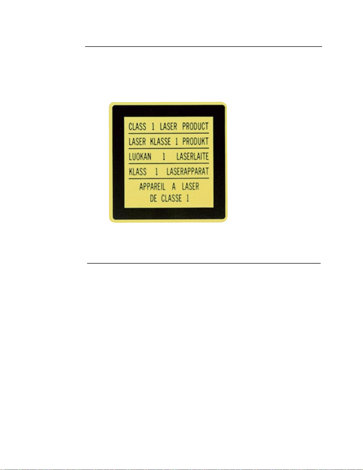
This label is fixed to the
bottom of the DVDROM Drive.
The equipment is classified as a Class 1 level laser product.
Labeling
Important Safeguards
Page 5

GD-2500 DVD-ROM Manual 5
• POWER SOURCE
•This DVD-ROM drive should be operated from the type of power
source indicated on the marked label. (+12V DC /+5V DC)
• TO AVOID THE RISK OF ELECTRIC SHORT CIRCUITS OR DAMAGE TO YOUR DVD-ROM
• Do not expose your DVD-ROM drive to rain or moisture.
• Do not open or remove the cover of your DVD-ROM drive.
• Turn off your SYSTEM and unplug the power supply cable of your
SYSTEM from the wall outlet before installing your DVD-ROM drive,
interface card or connecting cables.
• Do not allow foreign objects or liquids inside the DVD-ROM drive.
• Do not place heavy objects on the DVD-ROM drive.
• Do not use this DVD-ROM drive without mounting it.
• Firmly attach the DC power supply cable, connecting cables between
the DVD-ROM drive and other devices, and keep them connected
securely.
• IN CASE OF FAILURE
If any of the following conditions occur, immediately turn off the SYSTEM, including the
DVD-ROM drive, and unplug the power supply cable of the SYSTEM from the wall outlet Do
not attempt to service the DVD-ROM drive yourself, and refer servicing to qualified service
personnel immediately.
• Objects of any kind have been placed into your DVD-ROM drive.
• Liquid has been spilled into your DVD-ROM drive.
• Your DVD-ROM drive has been exposed to rain or water.
• Your DVD-ROM drive does not operate normally when the
operating instructions are followed.
• Your DVD-ROM drive has been dropped or damaged.
• Your DVD-ROM drive exhibits a distinct change in performance.
Precautions For Safety
Page 6

GD-2500 DVD-ROM Manual 6
• INSTALLATION CONDITIONS
Do not install your DVD-ROM drive under the following conditions. Dust on the pick-up
lens and/or disc, heat or vibration may negatively affect performance.
• In a place where an operation temperature reaches beyond the
specified temperature of 45˚C
• High humidity locations
• In a location subject to extreme changes of temperature and humidity
• In a room where dust density is higher than 0.1 mg/m
3
• In a room that has air conditioning with humidity control which may
scatter calcium combinations and other powdered substances
• In a room containing exhaust gas fumes such as exhaust gas from
gasoline or diesel engines or corrosive gas such as H2S (Hydrogen
sulfide)
• In a location subject to vibration and jarring during drive operation
• In a location subject to sudden shock and jolt during drive operation
• MOUNTING REQUIREMENTS
Use screws to mount your DVD-ROM drive tightly in the horizontal position. The
inclination of your DVD-ROM drive should be within 5˚ as shown below. The following
can occur if these requirements are not followed:
• The disc may jump out and be damaged when the tray is opened.
• Your DVD-ROM drive may be damaged.
• Your DVD-ROM drive may not function at full performance.
5˚
5˚
5˚
5˚
Precautions For Use
Page 7

GD-2500 DVD-ROM Manual 7
• MOUNTING SCREW
The screws must be ISO (M3X0.5) to mount the DVD-ROM drive tightly and to avoid
damaging the mechanism inside the DVD-ROM drive. (See page 10)
• MOVING YOUR DVD-ROM DRIVE
Remove the disc and close the disc tray before moving the DVD-ROM drive. If your DVDROM drive is moved with the disc loaded or the disc tray opened, both the disc and the
DVD-ROM drive may be damaged.
• CLEANING OF THE DVD-ROM DRIVE & DISCS
• Never clean your DVD-ROM drive and discs with silicon cloths or
cloths soaked in water, solvents (thinner, benzine), abrasive
cleaner, anti-static sprays, any record cleaner sprays, liquid cleaner or
aerosol cleaner. It may damage or discolor the coating of the
DVD-ROM drive and damage or deform discs.
• Clean your DVD-ROM drive including the disc tray and discs with a
clean, dry, soft cloth at least once a month.
• CLEANING OF DISC
If you begin to get error messages that your drive is unable to read a disc, it may mean that
cleaning is needed.
• Eject the disc and visually inspect the disc for scratches.
If there are scratches on the surface of the disc, change the disc.
• Eject the disc and clean as follows:
1. Clean the disc with a clean, dry, soft cloth.
2. Clean your DVD-ROM drive's pick-up lens using a cleaning disc.
Precautions For Care
Page 8

GD-2500 DVD-ROM Manual 8
7
8
9
1
10
Rear Panel
1) OPEN/CLOSE BUTTON
Press this button to open or close the disc tray.
2) DISC TRAY
When the power of the DVD-ROM drive is turned off, the disc tray
cannot be opened or closed.
3) MANUAL EMERGENCY EJECT HOLE
Only use in case of emergency. If the disc tray does not open when the
OPEN/CLOSE button is pressed, the DVD-ROM drive’s Manual Emergency
Eject mechanism may be activated. This should be used only in case of an
emergency. (See page 12 about Manual Emergency Eject Procedure)
4) LOADING/UNLOADING BUSY INDICATOR
Indicator blinks green only when the disc tray is being opened or closed, or when the
DVD-ROM drive is accessing data.
5) HEADPHONE JACK
The Headphone jack is an optional feature in the GD-2500 DVD model.
Depending on the manufacturer, this option may or may not be included in your drive.
6) HEADPHONE VOLUME CONTROL
The headphone volume control only exists on GD-2500 models with a headphone jack.
7) AUDIO OUTPUT TERMINAL
Front
Circuit Board
Rch GND Lch
Controls and Functions
2
3
4
65
Page 9

GD-2500 DVD-ROM Manual 9
8) DEVICE CONFIGURATION JUMPER
This connector is used to set operation modes such as Master, Slave
and CSEL
9) ATAPI INTERFACE CONNECTOR
ATAPI bus connection (40 pin)
10) POWER SUPPLY CONNECTOR (DC INPUT)
For connecting the power supply cable.
HARDWARE
• DVD-ROM drive
• Interface card
• Interface cable
• Power supply cable
• Mounting screws
Circuit Board
+5V GND +12V
Device is
Master
Device is
Slave
Cable
Select
or
(default setting)
6 4 2
5 3 1
Installation Requirements
Page 10

GD-2500 DVD-ROM Manual 10
HARDWARE OPTION
• Audio connecting cable
• Sound card
SOFTWARE
• DVD-ROM device driver
NOTE: If you need an interface card, interface cable or DVD-ROM device driver, contact your
dealer.
To install this DVD-ROM drive in the host computer, refer to the instruction manual of each
host computer. To install the interface card in the host computer, refer to the instruction
manual of each host computer and each interface card.
Install the DVD-ROM drive following the general installation procedure shown below:
1) Check the Device Configuration Jumper Settings of the DVD-ROM drive
such as Master, Slave, CSEL. (See page 9)
2) Turn off the host computer and unplug the power supply cable of the host
computer.
3) Remove the host computer cover.
4) Install the DVD-ROM drive into the host computer and mount tightly
with screws.
5) Check the settings of the interface card.
6) Install the interface card in the slot.
7) Firmly attach the interface cable from the interface card to the DVD-ROM
drive.
8) Firmly attach audio connecting cable as required.
9) Finally, firmly attach a spare DC power supply cable from the computer
power supply to the DVD-ROM drive.
10) Install the host computer cover.
Hardware Installation
Page 11

GD-2500 DVD-ROM Manual 11
1) Turn on the SYSTEM, including the DVD-ROM drive.
2) Press the OPEN/CLOSE button of the DVD-ROM drive to open the disc tray.
3) Place the disc in the center of the disc tray, label side up as shown on the
following page.
4) To close the disc tray, press the OPEN/CLOSE button on the DVD-ROM drive
or push lightly on the center of the front of the disc tray as shown below. The
disc tray will automatically close the rest of the way.
5) Follow the instruction manual of DVD-ROM device driver.
To install DVD-ROM device driver in the host computer to operate this DVD-ROM drive,
refer to the instruction manual of each DVD-ROM device driver.
Power supply cable
Interface cable
Audio connecting cable
Software Installation
Drive Operation
Page 12

GD-2500 DVD-ROM Manual 12
IMPORTANT:
• Do not press the OPEN/CLOSE button while the host computer is
accessing the disc. It may cause an error.
• When not using the DVD-ROM drive, keep the disc tray closed. It will
prevent the entry of dust and dirt, and reduce the requirements for disc
and lens cleaning.
CAUTION:
If you do not observe the following items, you may have problems opening and/or
closing the disc tray, and damage may be caused to the mechanism of the DVD-ROM
drive.
• Never use a damaged, broken or deformed disc.
• Do not press down hard on the disc tray when opening and closing it.
120 mm Disc
Label side
Push
Disc tray
Only in case of emergency:
If the disc tray does not open when the OPEN/CLOSE button is pressed, make sure
that the power of the DVD-ROM drive is turned on and that the lock function has
not been activated. If the disc tray still will not open, the DVD-ROM drive’s
Manual Emergency Eject Mechanism may still be activated. This should be used
only in case of an emergency.
Emergency Eject Procedure
Page 13

GD-2500 DVD-ROM Manual 13
A commercially available “Laser Lens Cleaning Disc” may be used to clean up the
pick-up lens of the DVD-ROM drive. Use the Compact Disc Laser Lens Cleaner LLC-1.
(by AUDIO SOURCE in U.S.A., by AKUSTIK SISTEME VERTRIEBS GHBH in GERMANY
and by SAEC COMMERCE CO., LTD. in JAPAN.)
1) Turn on the DVD-ROM drive.
2) Using the small brush supplied with the cleaning disc case, straighten up
the disc cleaning brushes on the back of the cleaning disc.
3) Place the cleaning disc in the disc tray with its arrow marked on the
disc at front.
4) Press the OPEN/CLOSE button or push the center of the disc tray
lightly and close the disc tray.
5) After about 20 seconds, the pick-up lens is cleaned by the cleaning disc.
6) Press the OPEN/CLOSE button and remove the cleaning disc.
7) Set the cleaning disc in its case with the disc cleaning brushes in the pad
hole.
8) Restart the SYSTEM.
1. Turn off the DVD-ROM drive and wait at
least 15 seconds until the disc stops
rotating.
2. Insert a straightened paper clip into
the Manual Emergency Eject Hole about 25
mm (1 inch).
3. Pull the disc tray.
NOTE: If it is necessary to use the emergency eject procedure to open the drive, the
tray should be closed by turning on the power and pressing the OPEN/CLOSE button.
Transporting the drive before it has been properly closed may cause damage to the
mechanism.
Removal Procedure
Lens Cleaning
Page 14

GD-2500 DVD-ROM Manual 14
• If your DVD-ROM drive does not operate properly, check the following
table.
• You may have to check the other devices included in your SYSTEM.
• If you cannot locate the cause of the problem, turn off the power of the SYSTEM,
including the DVD-ROM drive, immediately unplug the power supply
cable of the SYSTEM from the wall outlet, and contact your dealer.
• When calling for service, provide the following information:
1. Model name
2. Detailed symptoms
Symptoms Possible causes Remedy
The DVD-ROM
Drive does not
operate even when
a disc is loaded.
1. You place the
disc upside down in
the Disc Tray.
2. The disc is dirty.
3. The pick-up lens
is dirty.
4. The disc is
scratched or
warped.
5. Cable
connection is
incorrect.
1. Place the disc
right side up in the
Disc Tray, then load
it.
2. Clean the disc
surface.
3. Clean up the
pick-up lens. (see
page 13)
4. Change the disc.
5. Turn off your
SYSTEM and
reconnect cables
correctly.
The Disc Tray
cannot be opened.
Communications
between the host
computer and the
devices on the
interface cable are
not successful.
1. There are
devices with the
same Device
Configuration
jumper setting on
the interface cable.
1. Give each
device a different
Configuration
Jumper Setting.
Trouble Shooting
Page 15

GD-2500 DVD-ROM Manual 15
5.0
79.3±0.5
47.5±0.5
41.3
10±0.5
21.8±0.5
(A)
(A)
(A)
(A)
(A)
(A)
(A)
(A)
12-M2
Depth: Max. 5
A: Hole
139.8±0.5
146.0
190.0
42.7
149.0
5 mm
max.
Surface of the
CD-ROM drive
Mounting Screw
M3x0.5
Mounting frame of
computer
A) Hole Detail
DVD-ROM Drive
Mechanical Dimensions
 Loading...