

Hitachi DVPF-74-U Service Manual
SERVICE MANUAL
TK No. 0406E
DV-PF74U
DV-PF74U(C)
DO NOT RESELL OR DIVERT IMPROPERLY.DO NOT RESELL OR DIVERT IMPROPERLY.
SPECIFICATIONS AND PARTS ARE SUBJECT TO CHANGE FOR IMPROVEMENT
DVD PLAYER & VIDEO CASSETTE RECORDER
March 2004
Digital Media Division, Tokai

CONTENTS
1 CAUTIONS FOR SAFETY IN PERFORMING
REPAIR . . . . . . . . . . . . . . . . . . . . . . . . . . . . . . . .1-1
1-1 LASER BEAM SAFETY PRECAUTIONS . . . . . . . . 1-1
1-2 IMPORTANT SAFETY PRECAUTIONS . . . . . . . . . 1-2
1-2-1 Product Safety Notice . . . . . . . . . . . . . . . . . . . . . 1-2
1-2-2 Precautions during Servicing . . . . . . . . . . . . . . . 1-2
1-2-3 Safety Check after Servicing. . . . . . . . . . . . . . . . 1-3
1-3 STANDARD NOTES FOR SERVICING. . . . . . . . . . 1-4
1-3-1 Circuit Board Indications . . . . . . . . . . . . . . . . . . . 1-4
1-3-2 Instructions for Connectors . . . . . . . . . . . . . . . . . 1-4
1-3-3 Pb (Lead) Free Solder. . . . . . . . . . . . . . . . . . . . . 1-4
1-3-4 How to Remove/Install Flat Pack-IC . . . . . . . . . . 1-4
1-3-5 Instructions for Handling Semi-conductors . . . . . 1-7
2 GENERAL INFORMATION. . . . . . . . . . . . . . . . .2-1
2-1 SPECIFICATIONS. . . . . . . . . . . . . . . . . . . . . . . . . . 2-1
2-2 COMPARISON OF MODELS. . . . . . . . . . . . . . . . . . 2-2
2-2-1 General . . . . . . . . . . . . . . . . . . . . . . . . . . . . . . . . 2-2
2-2-2 VCR Section . . . . . . . . . . . . . . . . . . . . . . . . . . . . 2-2
2-2-3 DVD Section . . . . . . . . . . . . . . . . . . . . . . . . . . . . 2-3
2-3 COMPARISON OF MAIN CONTROL ICS . . . . . . . . 2-4
2-4 LIST OF ABBREVIATIONS AND TERMS
FOR DVD PLAYER . . . . . . . . . . . . . . . . . . . . . . . . . 2-5
2-5 FUNCTION INDICATOR SYMBOLS . . . . . . . . . . . . 2-6
2-6 OPERATING CONTROLS AND FUNCTIONS. . . . . 2-7
3 MAINTENANCE AND INSPECTION. . . . . . . . . .3-1
3-1 TROUBLESHOOTING. . . . . . . . . . . . . . . . . . . . . . . 3-1
3-1-1 Power Supply Section. . . . . . . . . . . . . . . . . . . . . 3-1
3-1-2 DVD Section . . . . . . . . . . . . . . . . . . . . . . . . . . . . 3-4
3-1-3 VCR Section . . . . . . . . . . . . . . . . . . . . . . . . . . . . 3-8
3-2 FIRMWARE RENEWAL MODE. . . . . . . . . . . . . . . 3-15
3-2-1 How to Update the Firmware Version . . . . . . . . 3-15
3-2-2 How to Verify the Firmware Version . . . . . . . . . 3-16
3-3 STANDARD MAINTENANCE. . . . . . . . . . . . . . . . . 3-17
3-3-1 Service Schedule of Components. . . . . . . . . . . 3-17
3-3-2 Cleaning . . . . . . . . . . . . . . . . . . . . . . . . . . . . . . 3-18
4 ADJUSTMENT . . . . . . . . . . . . . . . . . . . . . . . . . .4-1
4-1 PREPARATION FOR SERVICING. . . . . . . . . . . . . . 4-1
4-1-1 How to Enter the Service Mode. . . . . . . . . . . . . . 4-1
4-2 FIXTURE AND TAPE FOR ADJUSTMENT. . . . . . . 4-2
4-2-1 How to Use The Fixtures And Tape. . . . . . . . . . . 4-2
4-3 ELECTRICAL ADJUSTMENT INSTRUCTIONS . . . 4-3
4-3-1 Test Equipment Required . . . . . . . . . . . . . . . . . . 4-3
4-3-2 Head Switching Position Adjustment. . . . . . . . . . 4-3
4-4 MECHANICAL ALIGNMENT PROCEDURES. . . . . 4-4
4-4-1 Service Information. . . . . . . . . . . . . . . . . . . . . . . 4-4
4-4-2 Tape Interchangeability Alignment . . . . . . . . . . . 4-5
1-A. Preliminary/Final Check ing and
Alignment of Tape Path. . . . . . . . . . . . . . . . . . . . 4-6
1-B. X Value Alignment. . . . . . . . . . . . . . . . . . . . . . . . 4-6
1-C. Checking/Adjustment of Envelope Waveform . . . 4-7
1-D. Azimuth Alignment of
Audio/Control/Erase Head. . . . . . . . . . . . . . . . . . 4-8
5 DISASSEMBLY . . . . . . . . . . . . . . . . . . . . . . . . . 5-1
5-1 CABINET DISASSEMBLY INSTRUCTIONS . . . . . . .5-1
5-1-1 Disassembly Flowchart. . . . . . . . . . . . . . . . . . . . .5-1
5-1-2 Disassembly Method. . . . . . . . . . . . . . . . . . . . . . .5-1
5-2 DISASSEMBLY/ASSEMBLY PROCEDURES
OF DECK MECHANISM . . . . . . . . . . . . . . . . . . . . . .5-6
5-3 ALIGNMENT PROCEDURES OF MECHANISM . .5-15
6 EXPLODEDS VIEWS AND PARTS LIST . . . . . 6-1
6-1 EXPLODED VIEWS . . . . . . . . . . . . . . . . . . . . . . . . .6-1
6-1-1 Cabinet Section. . . . . . . . . . . . . . . . . . . . . . . . . . .6-1
6-1-2 Deck Mechanism View 1 Section . . . . . . . . . . . . .6-2
6-1-3 Deck Mechanism View 2 Section . . . . . . . . . . . . .6-2
6-1-4 Deck Mechanism View 3 Section . . . . . . . . . . . . .6-3
6-2 REPLACEMENT PARTS LIST. . . . . . . . . . . . . . . . . .6-4
6-2-1 Mechanical Parts List . . . . . . . . . . . . . . . . . . . . . .6-4
6-2-2 Electrical Parts List . . . . . . . . . . . . . . . . . . . . . . . .6-6
7 APPENDIX. . . . . . . . . . . . . . . . . . . . . . . . . . . . . 7-1
7-1 SYSTEM CONTROL TIMING CHARTS . . . . . . . . . .7-1
7-2 IC PIN FUNCTION DESCRIPTIONS. . . . . . . . . . . . .7-7
7-3 LEAD IDENTIFICATIONS . . . . . . . . . . . . . . . . . . . .7-10
S SCHEMATIC, WIRING DIAGRAMS
S-1 Schematic Diagrams/CBA’s and Test Points. . . . . . S-1
S-2 Wiring Diagram < VCR Section > . . . . . . . . . . . . . . S-3
S-3 Wiring Diagram < DVD Section > . . . . . . . . . . . . . . S-4
S-4 Main 1/8 Schematic Diagram. . . . . . . . . . . . . . . . . . S-5
S-5 Main 2/8, Sensor & Power SW Schematic
Diagrams. . . . . . . . . . . . . . . . . . . . . . . . . . . . . . . . . S-6
S-6 Main 3/8 Schematic Diagram. . . . . . . . . . . . . . . . . . S-7
S-7 Main 4/8 Schematic Diagram. . . . . . . . . . . . . . . . . . S-8
S-8 Main 5/8 Schematic Diagram. . . . . . . . . . . . . . . . . . S-9
S-9 Main 6/8 Schematic Diagram. . . . . . . . . . . . . . . . . S-10
S-10Main 7/8 & DVD Open/Close Schematic
Diagrams. . . . . . . . . . . . . . . . . . . . . . . . . . . . . . . . S-11
S-11Main 8/8 Schematic Diagram. . . . . . . . . . . . . . . . . S-12
S-12DVD Main 1/3 Schematic Diagram . . . . . . . . . . . . S-13
S-13DVD Main 2/3 Schematic Diagram . . . . . . . . . . . . S-14
S-14IC101 Voltage Chart . . . . . . . . . . . . . . . . . . . . . . . S-15
S-15DVD Main 3/3 Schematic Diagram . . . . . . . . . . . . S-16
S-16Waveforms. . . . . . . . . . . . . . . . . . . . . . . . . . . . . . . S-17
C CIRCUIT BOARD DIAGRAMS
C-1 Main CBA, Sensor CBA, DVD Open/Close CBA,
Power SW CBA Top View . . . . . . . . . . . . . . . . . . . . C-1
C-2 Main CBA Bottom View. . . . . . . . . . . . . . . . . . . . . . C-2
B BLOCK DIAGRAMS
B-1 Servo/System Control Block Diagram . . . . . . . . . . . B-1
B-2 Video Block Diagram. . . . . . . . . . . . . . . . . . . . . . . . B-2
B-3 Audio Block Diagram. . . . . . . . . . . . . . . . . . . . . . . . B-3
B-4 Hi-Fi Audio Block Diagram. . . . . . . . . . . . . . . . . . . . B-4
B-5 Power Supply Block Diagram. . . . . . . . . . . . . . . . . . B-5
B-6 DVD System Control/Servo Block Diagram. . . . . . . B-6
B-7 Digital Signal Process Block Diagram. . . . . . . . . . . B-7
B-8 DVD Video / Audio Block Diagram. . . . . . . . . . . . . . B-8
1
CAUTIONS FOR SAFETY IN PERFORMING REPAIR
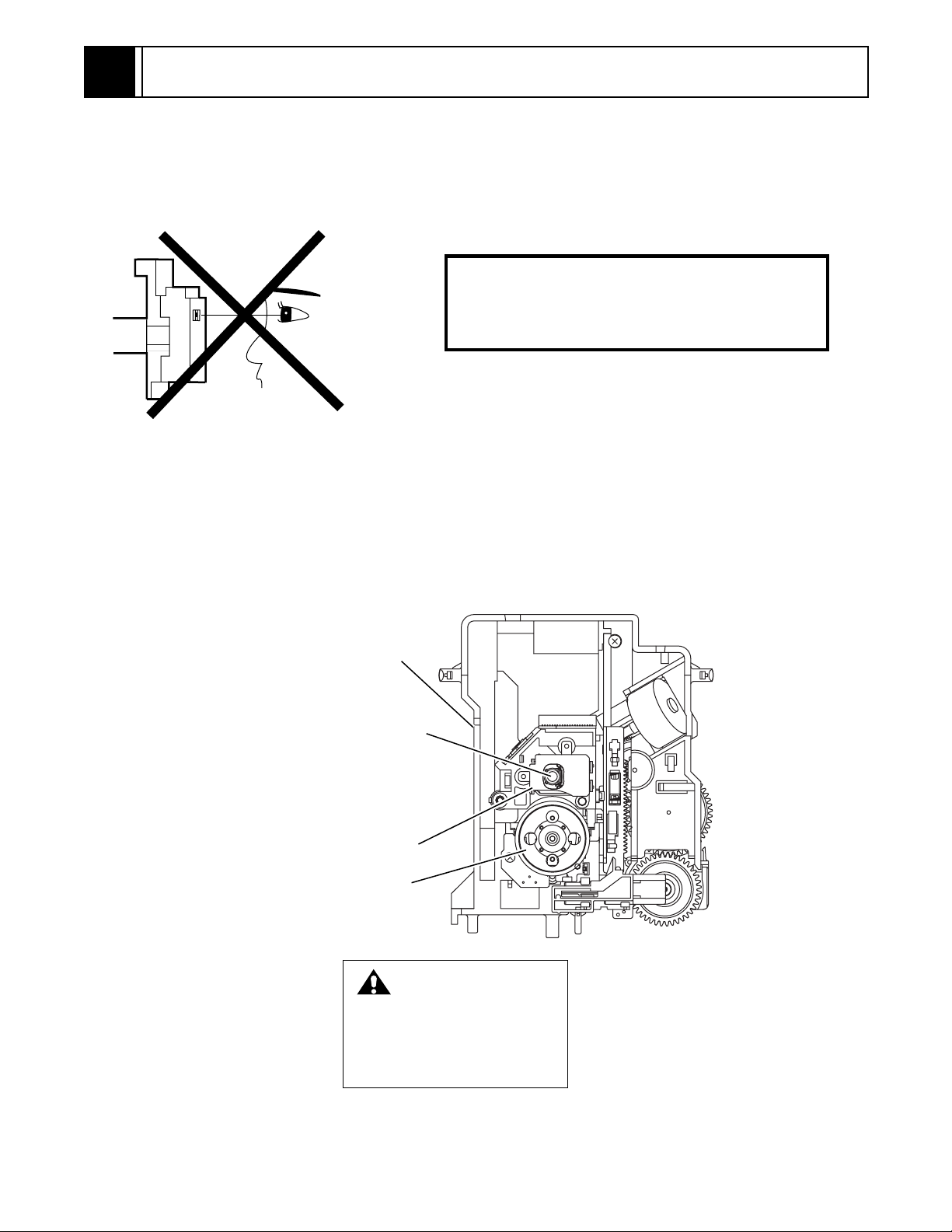
1-1 LASER BEAM SAFETY PRECAUTIONS
This DVD player uses a pickup that emits a laser beam.
Do not look directly at the laser beam coming
from the pickup or allow it to strike against your
skin.
The laser beam is emitted from the location shown in the figure. When checking the laser diode, be sure to keep
your eyes at least 30cm away from the pickup lens when the diode is turned on. Do not look directly at the laser
beam.
Caution: Use of controls and adjustments, or doing procedures other than those specified herein, may result in
hazardous radiation exposure.
Drive Mecha Assembly
Laser Beam Radiation
Laser Pickup
Turntable
CAUTION
LASER RADIATION
WHEN OPEN. DO NOT
STARE INTO BEAM.
Location: Top of DVD mechanism.
1-1

1-2 IMPORTANT SAFETY PRECAUTIONS
1-2-1 Product Safety Notice
Some electrical and mechanical parts have special
safety-related characteristics which are often not evident from visual inspection, nor can the protection they
give necessarily be obtained by replacing them with
components rated for higher voltage, wattage, etc.
Parts that have special safety characteristics are identified by a # on schematics and in parts lists. Use of a
substitute replacement that does not have the same
safety characteristics as the recommended replacement part might create shock, fire, and/or other hazards. The Product’s Safety is under review
continuously and new instructions are issued whenever appropriate. Prior to shipment from the factory,
our products are carefully inspected to confirm with
the recognized product safety and electrical codes of
the countries in which they are to be sold. However, in
order to maintain such compliance, it is equally important to implement the following precautions when a set
is being serviced.
1-2-2 Precautions during Servicing
A. Parts identified by the # symbol are critical for
safety. Replace only with part number specified.
B. In addition to safety, other parts and assemblies
are specified for conformance with regulations
applying to spurious radiation. These must also be
replaced only with specified replacements.
Examples: RF converters, RF cables, noise blocking capacitors, and noise blocking filters, etc.
C. Use specified internal wiring. Note especially:
1)Wires covered with PVC tubing
2)Double insulated wires
3)High voltage leads
D. Use specified insulating materials for hazardous
live parts. Note especially:
1)Insulation tape
2)PVC tubing
3)Spacers
4)Insulators for transistors
E. When replacing AC primary side components
(transformers, power cord, etc.), wrap ends of
wires securely about the terminals before soldering.
F. Observe that the wires do not contact heat produc-
ing parts (heatsinks, oxide metal film resistors, fusible resistors, etc.).
G. Check that replaced wires do not contact sharp
edges or pointed parts.
H. When a power cord has been replaced, check that
5 - 6 kg of force in any direction will not loosen it.
I. Also check areas surrounding repaired locations.
J. Be careful that foreign objects (screws, solder
droplets, etc.) do not remain inside the set.
K. Crimp type wire connector
The power transformer uses crimp type connectors
which connect the power cord and the primary side
of the transformer. When replacing the transformer,
follow these steps carefully and precisely to prevent
shock hazards.
Replacement procedure
1)Remove the old connector by cutting the wires at a
point close to the connector.
Important: Do not re-use a connector. (Discard it.)
2)Strip about 15 mm of the insulation from the ends
of the wires. If the wires are stranded, twist the
strands to avoid frayed conductors.
3)Align the lengths of the wires to be connected.
Insert the wires fully into the connector.
4)Use a crimping tool to crimp the metal sleeve at its
center. Be sure to crimp fully to the complete closure of the tool.
L. When connecting or disconnecting the internal
connectors, first, disconnect the AC plug from the
AC outlet.
1-2
1-2-3 Safety Check after Servicing
Examine the area surrounding the repaired location for
damage or deterioration. Observe that screws, parts,
and wires have been returned to their original positions. Afterwards, do the following tests and confirm
the specified values to verify compliance with safety
standards.
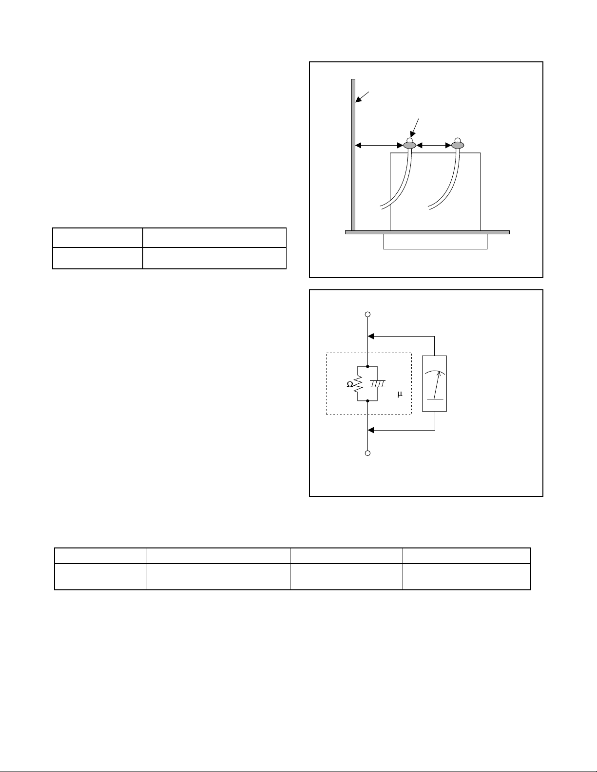
1. Clearance Distance
When replacing primary circuit components, confirm
specified clearance distance (d) and (d’) between soldered terminals, and between terminals and surrounding metallic parts. (See Fig. 1)
Table 1 : Ratings for selected area
AC Line Voltage Clearance Distance (d) (d’)
Chassis or Secondary Conductor
Primary Circuit Terminals
dd'
120 V
Note: This table is unofficial and for reference only.
Be sure to confirm the precise values.
2. Leakage Current Test
Confirm the specified (or lower) leakage current
between B (earth ground, power cord plug prongs)
and externally exposed accessible parts (RF terminals, antenna terminals, video and audio input and
output terminals, microphone jacks, earphone jacks,
etc.) is lower than or equal to the specified value in the
table below.
Measuring Method (Power ON) :
Insert load Z between B (earth ground, power cord
plug prongs) and exposed accessible parts. Use an
AC voltmeter to measure across the terminals of load
Z. See Fig. 2 and the following table.
Table 2: Leakage current ratings for selected areas
AC Line Voltage Load Z Leakage Current (i) Earth Ground (B) to:
120 V
≥ 3.2mm (0.126 inches)
0.15µF CAP. & 1.5kΩ RES.
Connected in parallel
Exposed Accessible Part
Z
1.5k
i≤0.5mA Peak Exposed accessible parts
0.15 F
Earth Ground
B
Power Cord Plug Prongs
AC Voltmeter
(High Impedance)
Fig. 1
Fig. 2
Note: This table is unofficial and for reference only. Be sure to confirm the precise values.
1-3
1-3 STANDARD NOTES FOR SERVICING
1-3-1 Circuit Board Indications
a. The output pin of the 3 pin Regulator ICs is indi-
cated as shown.
Top View
Out
b. For other ICs, pin 1 and every fifth pin are indicated
as shown.
Pin 1
c. The 1st pin of every male connector is indicated as
shown.
Input
In
Bottom View
5
10
1-3-3 Pb (Lead) Free Solder
When soldering, be sure to use the Pb free solder.
1-3-4 How to Remove / Install Flat
Pack-IC
1. Removal
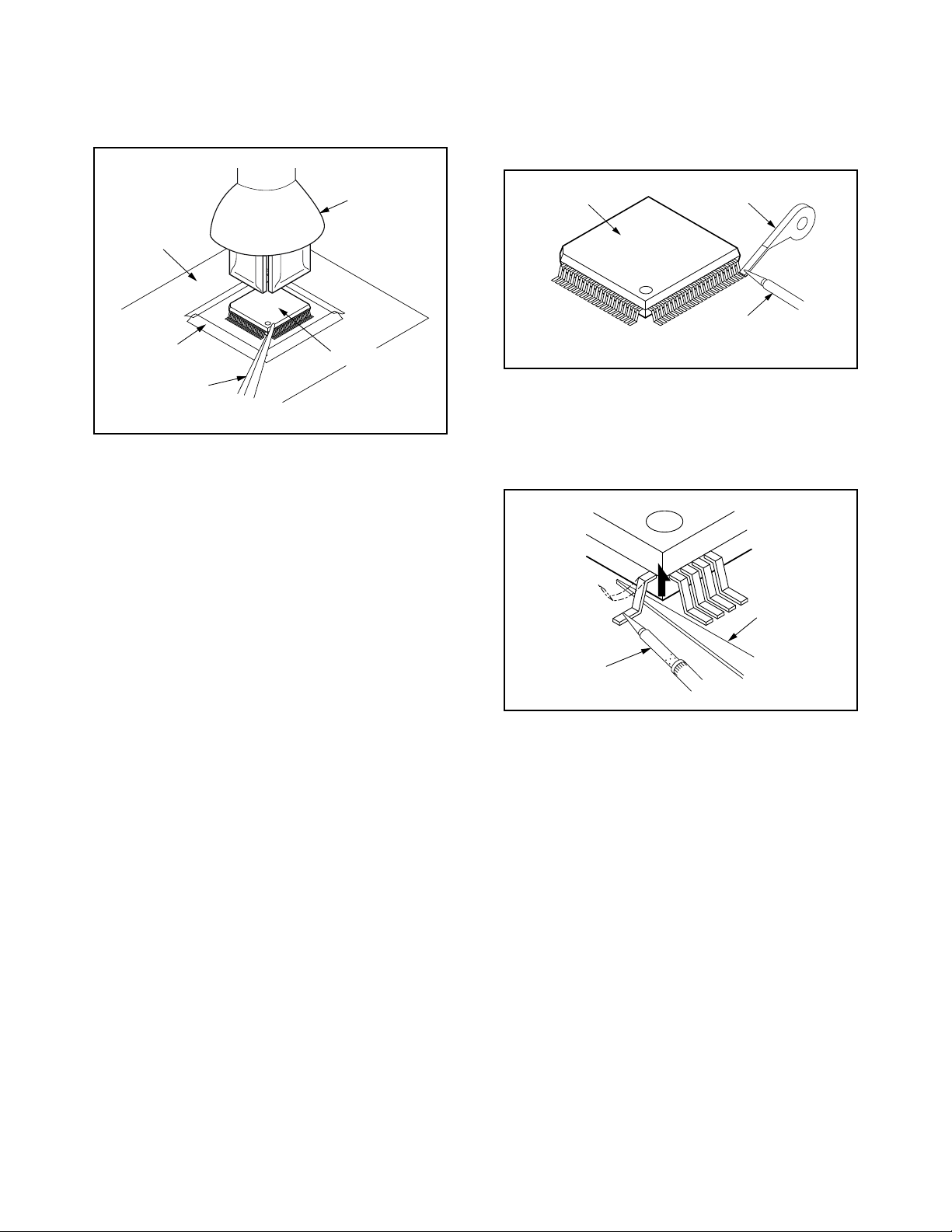
With Hot-Air Flat Pack-IC Desoldering Machine:.
(1) Prepare the hot-air flat pack-IC desoldering
machine, then apply hot air to the Flat Pack-IC
(about 5 to 6 seconds). (Fig. S-1-1)
Pin 1
1-3-2 Instructions for Connectors
1. When you connect or disconnect the FFC (Flexible
Foil Connector) cable, be sure to first disconnect
the AC cord.
2. FFC (Flexible Foil Connector) cable should be
inserted parallel into the connector, not at an angle.
FFC Cable
Connector
CBA
* Be careful to avoid a short circuit.
Fig. S-1-1
(2) Remove the flat pack-IC with tweezers while apply-
ing the hot air.
(3) Bottom of the flat pack-IC is fixed with glue to the
CBA; when removing entire flat pack-IC, first apply
soldering iron to center of the flat pack-IC and heat
up. Then remove (glue will be melted). (Fig. S-1-6)
(4) Release the flat pack-IC from the CBA using twee-
zers. (Fig. S-1-6)
Caution:
1. The Flat Pack-IC shape may differ by models. Use
an appropriate hot-air flat pack-IC desoldering
machine, whose shape matches that of the Flat
Pack-IC.
2. Do not supply hot air to the chip parts around the
flat pack-IC for over 6 seconds because damage to
the chip parts may occur. Put masking tape around
the flat pack-IC to protect other parts from damage.
(Fig. S-1-2)
1-4
3. The flat pack-IC on the CBA is affixed with glue, so
be careful not to break or damage the foil of each
pin or the solder lands under the IC when removing
it.
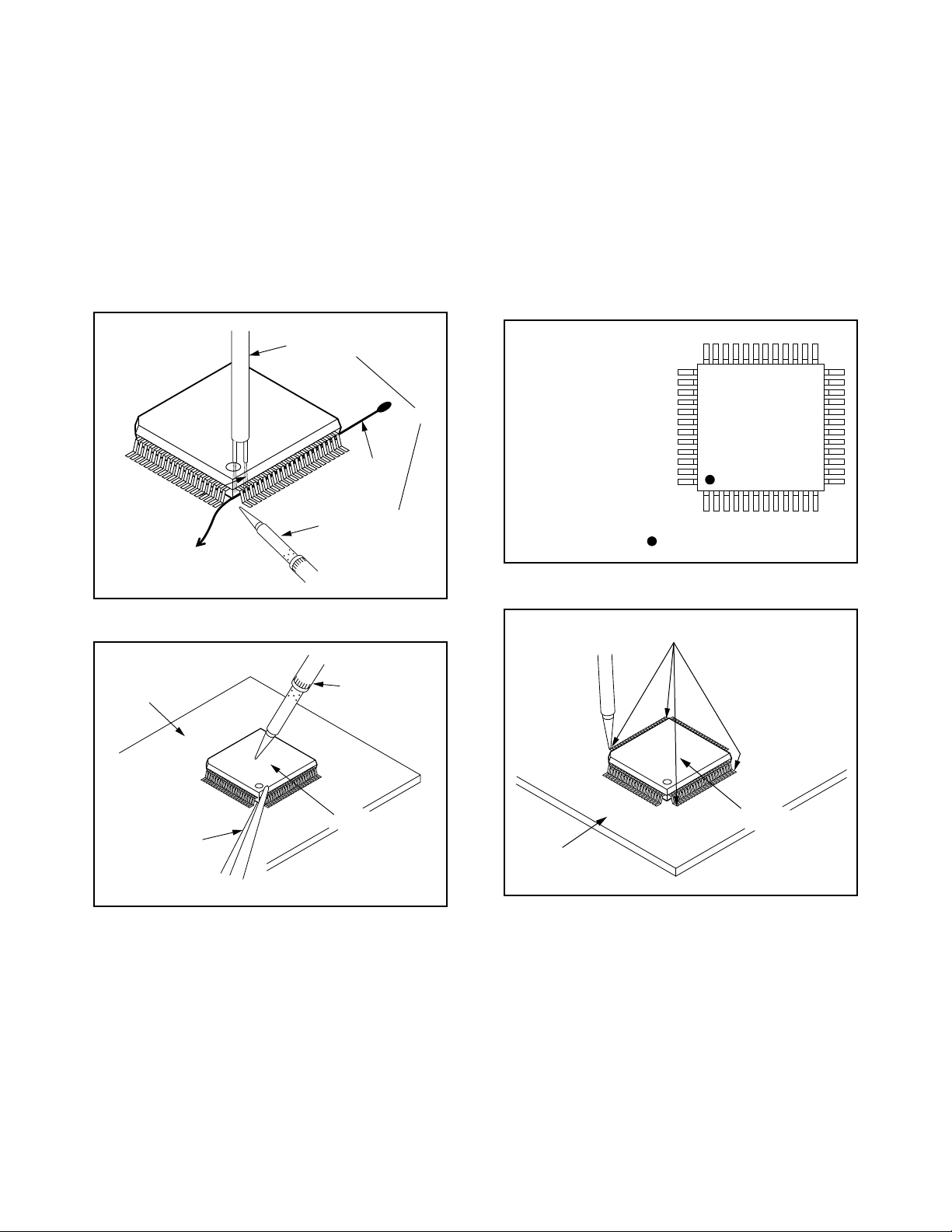
With Soldering Iron:
(1) Using desoldering braid, remove the solder from all
pins of the flat pack-IC. When you use solder flux
which is applied to all pins of the flat pack-IC, you
can remove it easily. (Fig. S-1-3)
CBA
Masking
Tape
Tweezers
Hot-air
Flat Pack-IC
Desoldering
Machine
Flat Pack-IC
Fig. S-1-2
Flat Pack-IC
Desoldering Braid
Soldering Iron
Fig. S-1-3
(2) Lift each lead of the flat pack-IC upward one by
one, using a sharp pin or wire to which solder will
not adhere (iron wire). When heating the pins, use
a fine tip soldering iron or a hot air desoldering
machine. (Fig. S-1-4)
Sharp
Pin
Fine Tip
Soldering Iron
(3) Bottom of the flat pack-IC is fixed with glue to the
CBA; when removing entire flat pack-IC, first apply
soldering iron to center of the flat pack-IC and heat
up. Then remove (glue will be melted). (Fig. S-1-6)
(4) Release the flat pack-IC from the CBA using twee-
zers. (Fig. S-1-6)
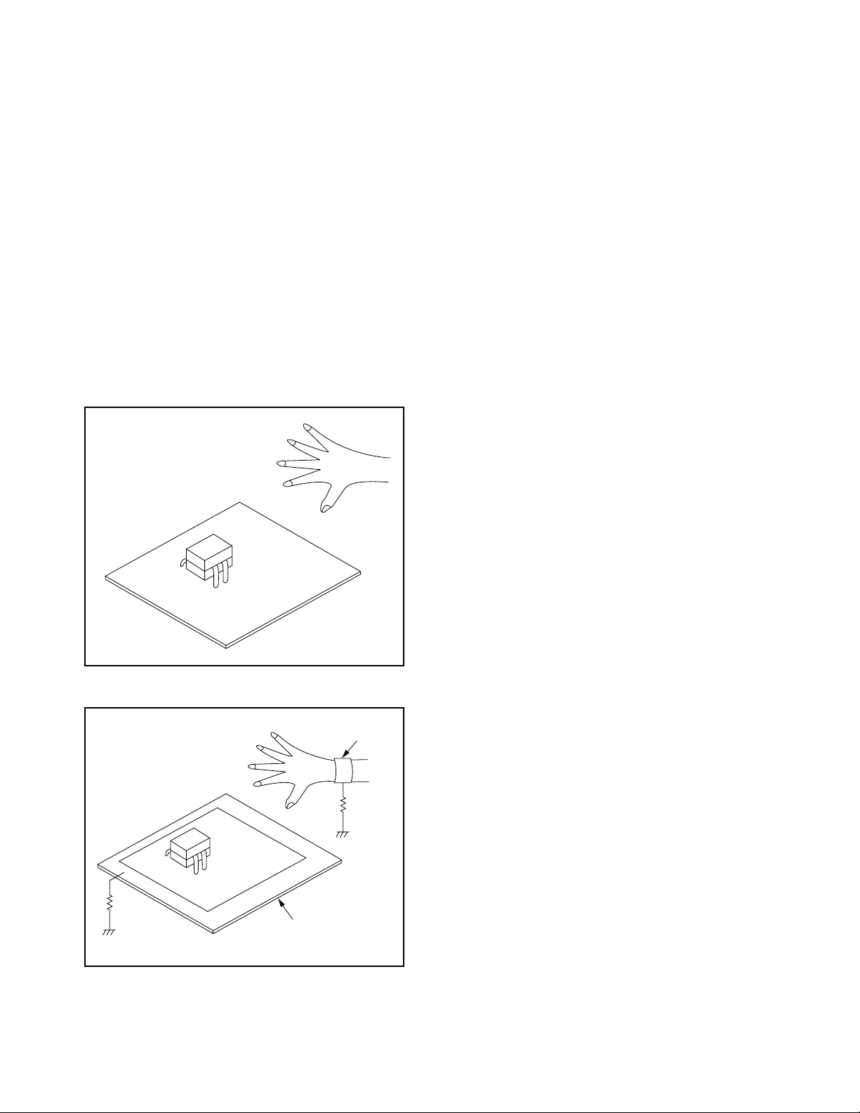
With Iron Wire:
(1) Using desoldering braid, remove the solder from all
pins of the flat pack-IC. When you use solder flux
which is applied to all pins of the flat pack-IC, you
can remove it easily. (Fig. S-1-3)
(2) Affix the wire to a workbench or solid mounting
point, as shown in Fig. S-1-5.
(3) While heating the pins using a fine tip soldering
iron or hot air blower, pull up the wire as the solder
melts so as to lift the IC leads from the CBA contact
pads as shown in Fig. S-1-5
Fig. S-1-4
1-5
(4) Bottom of the flat pack-IC is fixed with glue to the
CBA; when removing entire flat pack-IC, first apply
soldering iron to center of the flat pack-IC and heat
up. Then remove (glue will be melted). (Fig. S-1-6)
(5) Release the flat pack-IC from the CBA using twee-
zers. (Fig. S-1-6)
Note:
When using a soldering iron, care must be taken
to ensure that the flat pack-IC is not being held by
glue. When the flat pack-IC is removed from the
CBA, handle it gently because it may be damaged
if force is applied.
2. Installation
(1) Using desoldering braid, remove the solder from
the foil of each pin of the flat pack-IC on the CBA so
you can install a replacement flat pack-IC more
easily.
(2) The “I” mark on the flat pack-IC indicates pin 1.
(See Fig. S-1-7.) Be sure this mark matches the 1
on the PCB when positioning for installation. Then
presolder the four corners of the flat pack-IC. (See
Fig. S-1-8.)
(3) Solder all pins of the flat pack-IC. Be sure that none
of the pins have solder bridges.
To Solid
Mounting Point
CBA
Hot Air Blower
Iron Wire
Soldering Iron
Fig. S-1-5
Fine Tip
Soldering Iron
or
Example :
Pin 1 of the Flat Pack-IC
is indicated by a " " mark.
Presolder
Fig. S-1-7
Tweezers
Flat Pack-IC
Fig. S-1-6
Flat Pack-IC
CBA
Fig. S-1-8
1-6
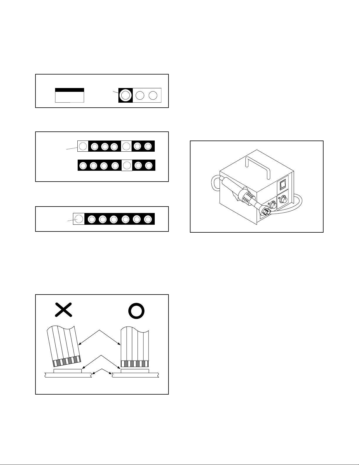
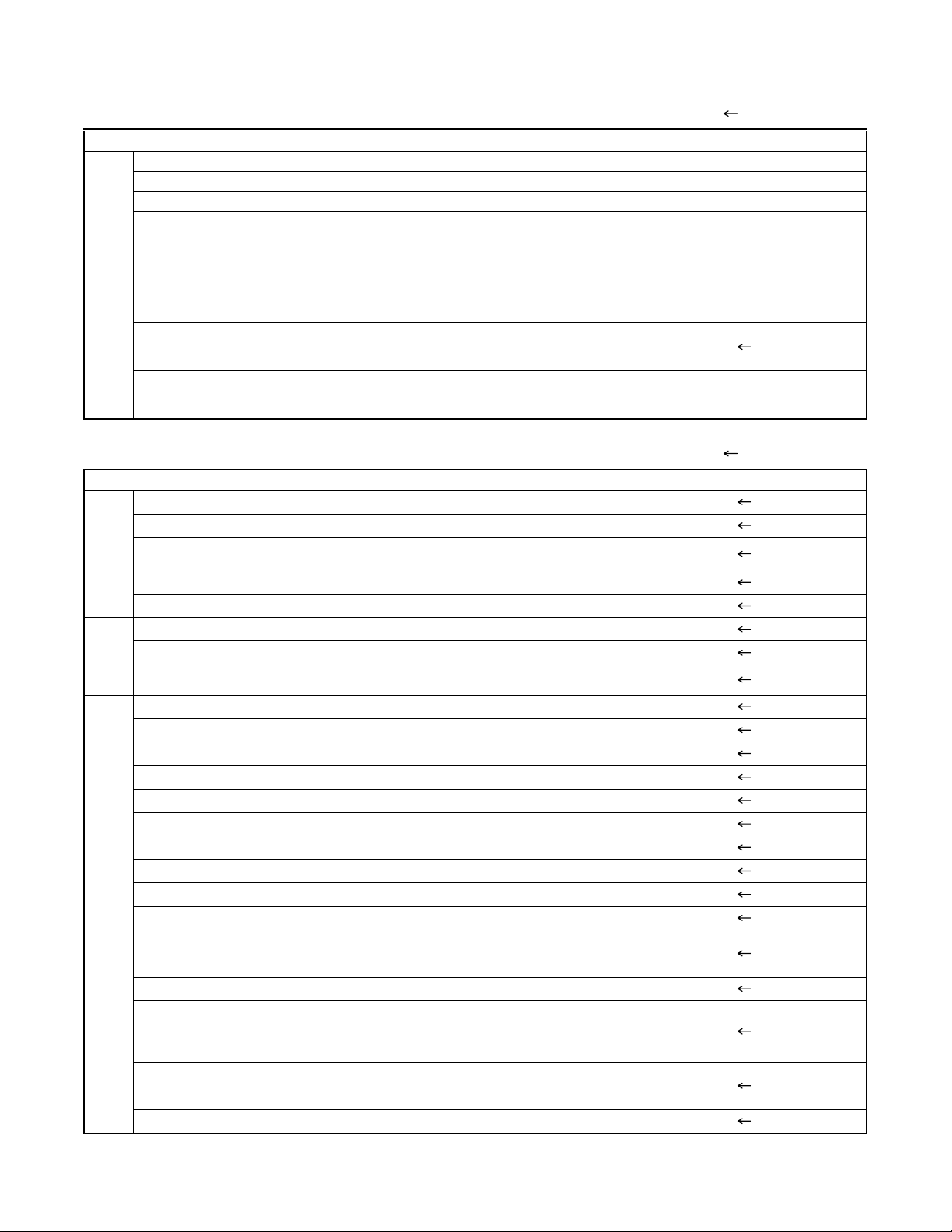
1-3-5 Instructions for Handling
Semi-conductors
Electrostatic breakdown of the semi-conductors may
occur due to a potential difference caused by electrostatic charge during unpacking or repair work.
1. Ground for Human Body
Be sure to wear a grounding band (1MΩ) that is properly grounded to remove any static electricity that may
be charged on the body.
2. Ground for Workbench
(4) Be sure to place a conductive sheet or copper plate
with proper grounding (1MΩ) on the workbench or
other surface, where the semi-conductors are to be
placed. Because the static electricity charge on
clothing will not escape through the body grounding band, be careful to avoid contacting semi-conductors with your clothing.
<Incorrect>
<Correct>
1MΩ
CBA
Grounding Band
1MΩ
CBA
Conductive Sheet or
Copper Plate
1-7

Product type: DVD/VCR Combo (DVD player with Video Cassette Recorder)
D
C
P
P
O
D
W
2
GENERAL INFORMATION
2-1 SPECIFICATIONS
iscs: DVD video
onverter output: VHF Channel 3 or 4.
ower source: 120 V AC +/- 10%, 60 Hz +/- 0.5%
ower consumption: 21 W (standby: 3.6 W)
perating temperature: 41 F (5 C) to 104 F (40 C)
imensions: W 17-3/16” (435 mm)
eight: 6.0 lbs (2.7 kg)
Audio CD
Video Cassette tape (VHS)
H 3-3/4” (94 mm)
D 9-3/16” (233 mm)
Designs and specifications are subject to change without notice.
If there is a discrepancy between languages, the default language will be English.
2-1
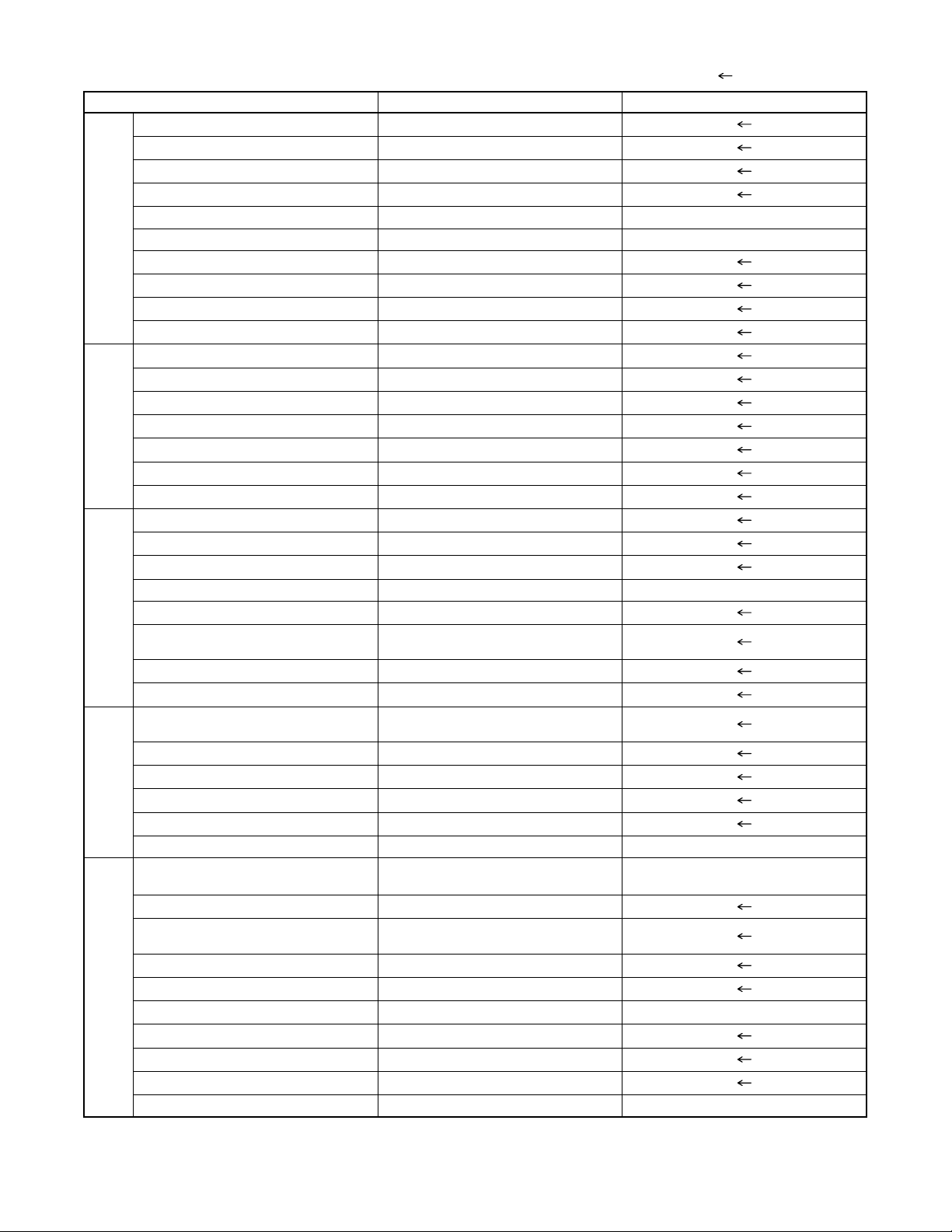
2-2 COMPARISON OF MODELS
2-2-1 General O: Yes, ---: No, : Same as on left
ITEM DV-PF74U/PF74U(C) DV-PF73U/PF73U(C)/PF33U
Dimensional 435(W) x 94(H) x 233(D)mm 435(W) x 99(H) x 218(D)mm
Weight 2.7 kg 3.6 kg
Tray Panel / FL Window Clear / Clear Silver / Clear
Color Front / Button Silver / Silver Silver / Silver (DV-PF73U/PF73U(C))
APPEARANCE
Remote Controller Model Name DV-RMPF74U
Jog Shuttle on Remote ---
DV-RMPF73U (DV-PF73U/PF73U(C))
DV-RMPF33U (DV-PF33U)
REMOTE
TV Control --- O
CONTROLLER
2-2-2 VCR Section O: Yes, ---: No, : Same as on left
ITEM DV-PF74U/PF74U(C) DV-PF73U/PF73U(C)/PF33U
Video Format VHS
Y/C Separation Comb Filter
YNR (Luminance Noise Reduction)
Circuit
VIDEO
New Synchronize Circuit --Picture Control --Video/Audio Input (Rear) 1/1 (IN1)
Video/Audio Input (Front) 1/1 (IN2)
INPUT/
Video/Audio Output (Rear) 1/1 (OUT1)
OUTPUT
Stereo CM Skip Feature --Auto Clock Feature --Number of Timer Programming 8 Program/year
Self Diagnosis Function O (4 Modes)
Back-up Time 30 s
OTHERMECHANISM
SQPB --Surge Absorber O
Auto Power Off Feature O
Local Broadcast Setting O
Multi Search Feature O (Index, Time Search)
Search Speed
FF/REW Time (T-120 Tape)
Head Composition
Video Head Material
VISS O (Index Search)
FF: approx. 4 min, REW: approx. 4 min
Hi-Fi Audio: 2[28/28 µm]
SP: X5
LP: X5/X9
EP: X5/X15
DA4+Hi-Fi
SP: 2[49/58 µm]
EP: 2[21/21 µm]
SP: Ferrite
EP: Ferrite
Hi-Fi Audio: Ferrite
O
2-2
2-2-3 DVD Section O: Yes, ---: No ( : Same as on left)
ITEM DV-PF74U/PF74U(C) DV-PF73U/PF73U(C)/PF33U
Drive Speed 1x
Laser 2
DVD/VCD/SVCD/CD-DA O / --- / --- / O
CD-R/CD-RW/DVD-R (Video Format) O / O / O
DVD-RAM/DVD-RW (Video Format) --- / O --- / ---
JPEG Play back O ---
MP3 O
GENERALVIDEOAUDIO
OSD languages 3 (English, French, Spanish)
Jog Shuttle on Front ---
Headphone Jack / Volume --- / ---
PAL Disc NTSC Out ---
Video Out Mode NTSC/PAL/PAL60 O / --- / ---
S-Video / Component / Composite O / O / O
Video D/A Converter 10bit
Black Level Select O
Picture Control ---
Progressive Out O
Audio D/A Converter 192kHz / 24bit
Digital Audio Out Optical / Coaxial --- / O
Dolby Digital 5.1 ch Decode ---
DTS Digital Out O ---
Virtual Surround O
Dynamic Range Compression (Dolby
Digital)
DVD Audio ---
Power on sound ---
Search Speed
Slow Speed 1/16, 1/8, 1/2 (FORWARD/REWIND)
IP Search (Smooth 2x Play) O
2x Play with Audio ---
Step Forward / Reverse O / O
TRICK PLAY
Still Picture Select (Frame/Field) Frame/Field/Auto Auto Only
Disc Navigation O
DVD Zoom x2 / x4 O / O
Program and Random Play of DVD /
VCD
A-B Repeat O
Repeat O
Last Play O
FEATURES
Closed Caption for NTSC DVD O
Front Panel Display Dimmer O
Screen Saver O
Auto Power Off O (always ON) O
2 to 100 (FORWARD/REWIND)
(DVD: 2, 8, 50, 100/CD: 16)
O
O (DV-PF73U/PF73U(C))
--- (DV-PF33U)
---
---
2-3
2-3 COMPARISON OF MAIN CONTROL ICS
: Same as on left
ITEM DV-PF74U/PF74U(C) DV-PF73U/PF73U(C)/PF33U
MICRO CONTROLLER MN35202 (IC101) MN35102 (IC101)
FLASH ROM MBM29LV160BM90TN (IC103) MBM29LV160BE90TN-K /
LATCH ---------- 74LVX573MTCX / TC74LVX573FT(EL)
SW NC7SB3157P6X / SN74LVC1G3157DCKR
OP AMP LM324PWR / LM324PT (IC202) KIA324F-EL (IC202)
SERVO DRIVE SA5694 / FAN8024CDTF / BA5954FP-E2 /
CLOCK GENERATOR ---------- BU2363FV-E2 (IC451)
RESET PST3229NR (IC461) PST9127NR / BMR-110527 (IC461)
SDRAM K4S641632H-UC75 / VDS6616A4A-7G
AUDIO D/A CONVERTER PCM1755DBQR (IC601) PCM1751DBQR (IC601)
VIDEO/AUDIO SIGNAL
PROCESS/HEAD AMP
MTS/SAP/Hi-Fi AUDIO
PROCESS/Hi-Fi HEAD AMP
SERVO/SYSTEM CONTROL MN101D08DFT (IC501) ----------
SYSTEM CONTROL
MICROPROCESSOR
FIP DRIVER PT6313-S-TP (IC571)
OUTPUT SELECT TC4053BF(N) / BU4053BCF /
ERROR VOLTAGE DET LTV-817B-F / LTV-817C-F / ELB817A /
1.2V REG PQ070XZ5MZP (IC1002) ----------
1.5V REG ---------- PQ070XF01SZ (IC1002)
3.3V REG BA3948FP-E2 (IC1004) PQ070XF01SZ (IC1004)
SHUNT REGULATOR ---------- KIA431-AT / TL431A-TA / KIA431A-AT
AMP KIA4558P / NJM4558D (IC1201)
VIDEO DRIVER MM1637XVBE (IC1402) MM1622XJBE (IC1402)
(IC201)
BA5888FP-E2 (IC301)
BMR-110529 (IC462)
(IC503)
LA71205M-MPB-E (IC301) LA71091M (IC301)
LA726708M-MPB-E (IC451) LA72670M (IC451)
---------- MN101D08EFD1/QSZACORMS006 (IC501)
CD4053BCSJX (IC751)
ELB817B / ELB817C / PS2561A-1(Q) /
PS2561A-1(W) (IC1001)
MM1636XWRE (IC1403)
MBM29LV1661390PFTNSFK /
HY29LV160BT-90 / MX29LV160BTC-90 /
M29W166DB70N6 (IC103)
(IC104, IC105)
NC7SB3157P6X (IC201)
SA5694 / BA5954FP-E2 (IC301)
K4S643232F-TC60 /
HY57V643220CT-(7,55) (IC102)
TC4053BF(N) / BU4053BCF (IC751)
LTV-817B-F (IC1001)
(IC1006)
2-4
2-4
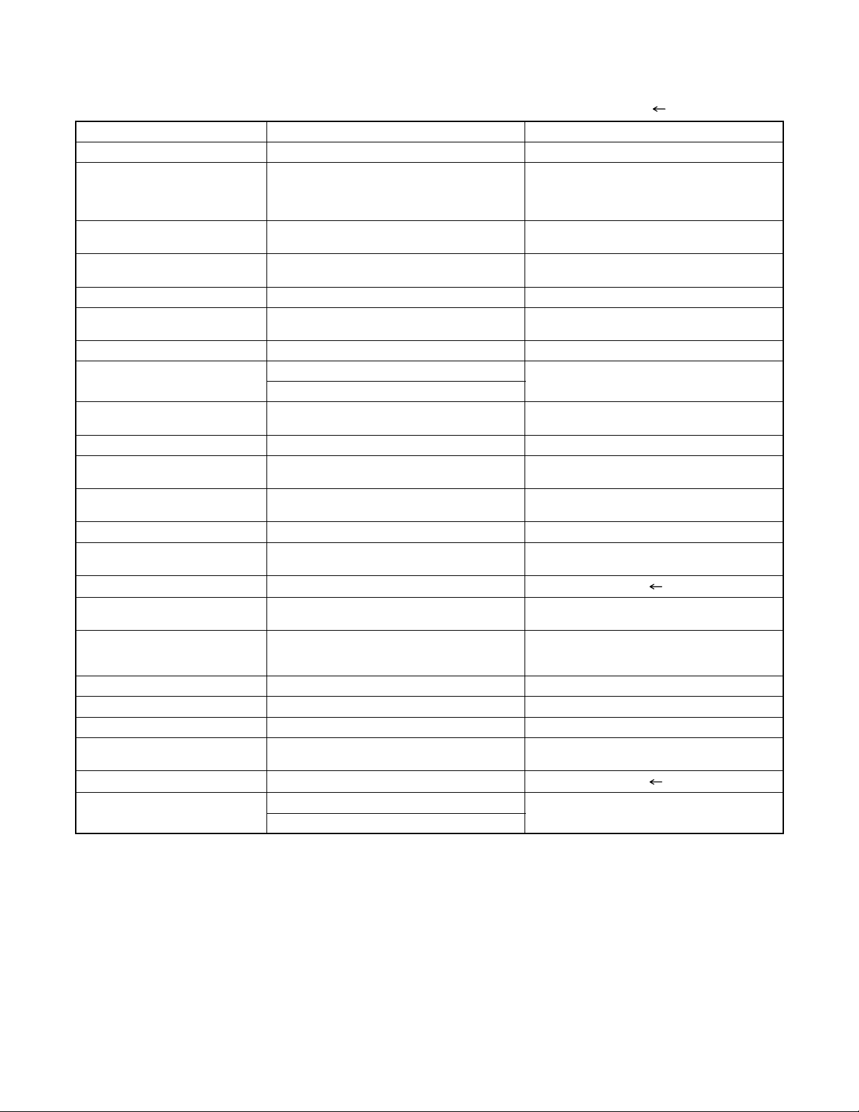
LIST OF ABBREVIATIONS AND TERMS FOR DVD PLAYER
Index Abbreviation/Term Explanation
A AC3 See Dolby AC3.
C CD-R One type of DVD standard disc, to which writing once is possible (recordable type)
CD-RW One type of CD standard disc, to which writing up to 1000 times is possible
Component video
output terminals
D Dolby AC3 Audio coding format developed by Dolby Laboratories in U.S, also simply referred to as AC3
D terminal This terminal, specified by EIAJ (currently JEITA), can automatically switch "digital hi-vision"
DTS Digital Theater System: Sound system as for movie theaters developed by US Digital Theater
DVD Digital Versatile Disc. A huge amount of digital data for video (movie) and audio can be
DVD-Audio One type of DVD standard disc, on which high-quality audio can be recorded
DVD-R One type of DVD standard disc, to which writing once is possible (recordable type)
DVD-RAM One type of DVD standard disc, to which writing up to 100,000 times is possible
DVD-ROM One type of DVD standard disc, to which data for computer can be recorded
DVD-RW One type of DVD standard disc, to which writing up to 1000 times is possible
DVD-Video One type of DVD standard disc, on which high-quality video and audio can be recorded
DVD Video Format Video recording/playback standard that applies to DVD-Video, DVD-R and DVD-RW
DVD Video Recording
Format
DVD Forum International organization that formulates the technical standards of DVD
E EIAJ Electronic Industries Association of Japan: An organization of manufacturers of consumer
J JPEG Joint Photographic Expert Group: International standard format for compressing still images.
L Linear PCM Linear Pulse Code Modulation: LPCM is a format that digitizes analog audio signal during
M MPEG Moving Picture Experts Group: Standard related to compression of digital video and audio.
MPEG Audio Layer 2 One of three audio compression standards (layers 1-3) defined by MPEG
MP3 MPEG1 Audio Layer-3: Audio data digital compression technology.
P Progressive playback
function
S SDMI Secure Digital Music Initiative: This conference was established by hardware makers, the
V Virtual surround This technology localizes sound at any position using only two front speakers, by subjecting
Used for outputs of HDTV video signal format. Since signals for brightness and colors are
independently handled for components signals (Y: luminance signal; PR/PB: chrominance
signals), degrading of image will be reduced.
format: Supports 5-channel full-range sound and one channel for sub-woofer sound
playback.
programs of BS digital broadcast, and "digital standard broadcast" of current image quality. A
tuner and TV can easily be connected to the D terminal. There are 5 types of D terminal,
depending on the different format of video signal passing thorough the D terminal.
Systems, Inc. The number of channels provided by DTS is the same for Dolby AC3.
recorded on this disc, whose size is the same as CD.
Video recording/playback standard that applies to DVD-RAM and DVD-RW: This allows
versatile editing functions, differing from the DVD Video Format.
electronic devices, industrial electronic devices and electronic components, established in
April 1948. EIAJ merged with JEIDA (Japan Electronic Industry Development Association) in
November 2000 to become JEITA (Japan Electronics and Information Technology Industries
Association).
recording and converts it back to analog signal during playback.
MPEG2 is a higher standard of MPEG and is applied to video (movie) requiring higher
quality.
This function converts interlaced images to non-interlaced images and displays them. It can
play back 24-frame/second images included in DVD movie software, etc.
Recording Industry Association of America (RIAA) and music industry companies, to protect
copyrights of musical compositions.
the L and R signals to matrix operation. It uses the four transfer functions from L/R speakers
located at specified positions to both ears of listener located in a specified position, taking
into account the shape of head and the effect of earlobes, and the two transfer functions from
any position to both ears.
2-5

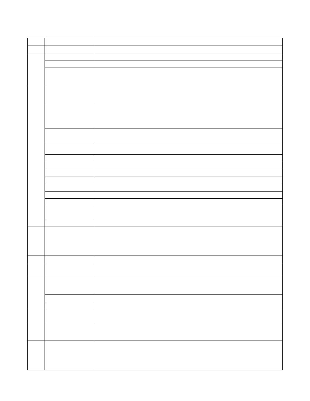
2-5 FUNCTION INDICATOR SYMBOLS
Note:
The following symbols will appear on the indicator panel to indicate the current mode or operation of the VCR.
On-screen modes will also be momentarily displayed on the tv screen when you press the operation buttons.
Led Mode Indicator Active
When reel and capstan mechanism is not
functioning correctly
When tape loading mechanism is not functioning correctly
When cassette loading mechanism is not
functioning correctly
When the drum is not working properly
“EJECT R” is displayed on a TV screen. (Refer to Fig. 1.)
“EJECT T” is displayed on a TV screen. (Refer to Fig. 2.)
“EJECT C” is displayed on a TV screen. (Refer to Fig. 3.)
“EJECT D” is displayed on a TV screen. (Refer to Fig. 4.)
TV screen
Note:
OSD for mechanical error will be displayed for 5 sec. after the mechanical error occurs.
When reel and capstan mechanism is not functioning
correctly
A
R
Fig. 1
When cassette loading mechanism is not functioning
correctly
A
C
Fig. 3
When tape loading mechanism is not functioning correctly
A T
Fig. 2
When the drum is not working properly
A
D
Fig. 4
2-6
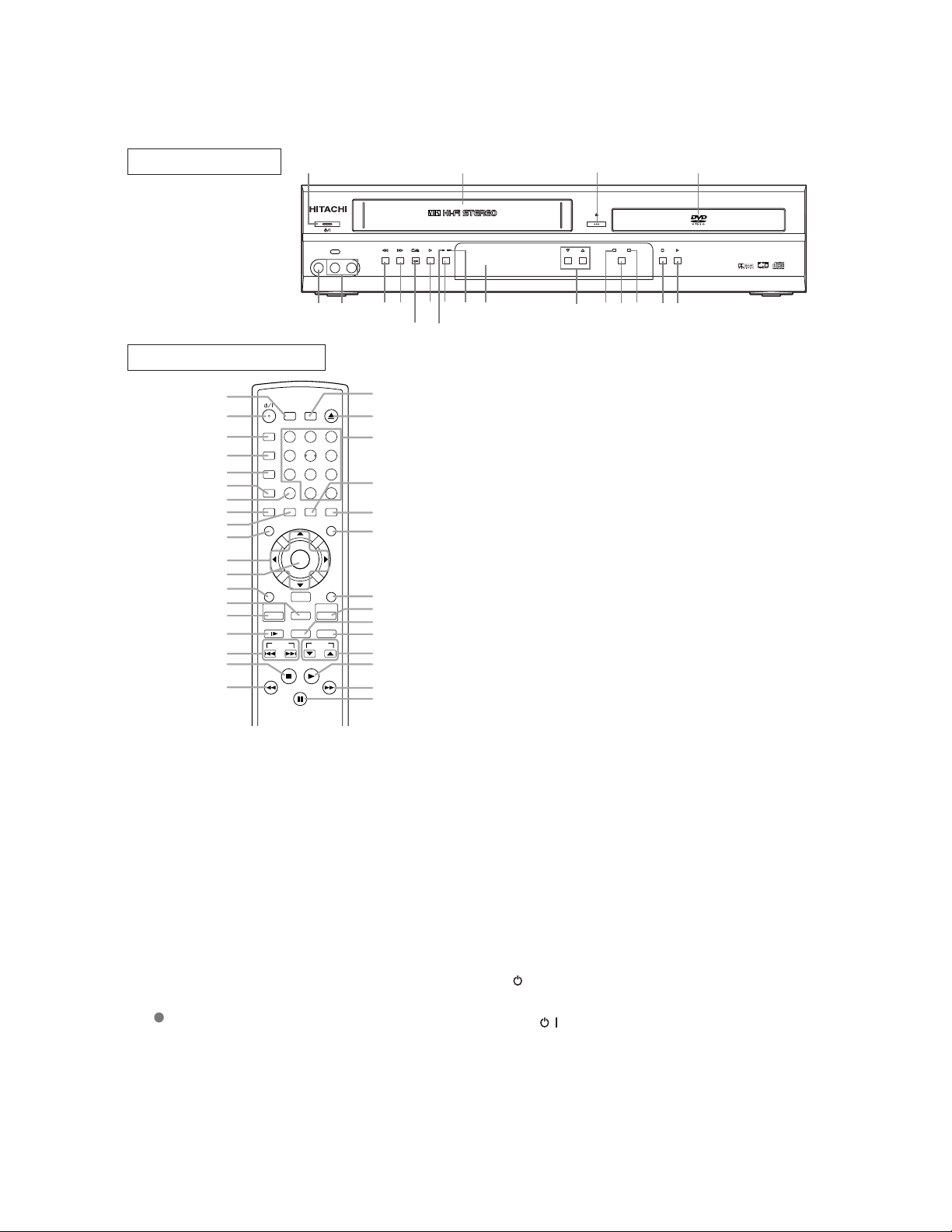
2-6 OPERATING CONTROLS AND FUNCTIONS
d.
T
e
e
e
w
c-
r
g.
ut
er
n
d-
in
a
a
sc
N
k.
e
ts
FRONT PANEL
1
POWER/STANDBY
VIDEO IN L [mode] AUDIO IN R
20
LINES
19
18
REW F. F W D
17
STOP/EJECT
16
PLAY
15
14
REMOTE CONTROL
21
22
A-B REPEAT
23
REPEAT
24
25
26
27
28
29
30
31
32
33
34
35
36
37
38
39
MODE
ZOOM
ANGLE
MENU
RETURN
VCR
SLOW SPEED REC/OTR
SURROUND
1
4
7
CLEAR/C. RESET
SUBTITLE
TIMER
SKIP
STOP
PAUSE/STEP
SEARCH MODE
56
8
0
AUDIO
ENTER
DISC
NAVIGATION
VCR/TV
PLAY
OPEN/CLOSE
EJECT
32
9
+10
DISPLAY
TOP MENU
SETUP
DVD
CH
1. POWER/STANDBY Button
Press to turn the power on and off.
2. CASSETTE COMPARTMENT
3. OPEN/CLOSE Button
Press to insert discs into or remove them from the tray.
4. Disc loading tray
5. PLAY Button (DVD)
Press to begin playback.
Press to switch between progressive mode and interlace
modes.
6. STOP Button (DVD)
Stops operation of the disc.
7. DVD OUTPUT Light (Green)
This light appears when the DVD output mode is selected.
You can only watch DVDs when the green DVD OUTPUT
Light is on. To make the green DVD OUTPUT light come
on, press DVD on the remote control or OUTPUT on the
front panel.
8. OUTPUT Button
Press to select DVD mode or VCR mode.
You can switch the output mode either by pressing
OUTPUT on the front panel, or by pressing DVD or
VCR on the remote control. However, if you press
OUTPUT on the front panel first, you need to reselect the corresponding mode by pressing DVD or
VCR on the remote control.
53
52
51
50
49
48
47
46
45
44
43
42
41
40
CHANNEL
3
OPEN/CLOSE
VCR
OUTPUT
2
DIGITAL AUTO TRACKING
RECTIMER
REC/OTR
PROGRESSIVE SCAN
9. VCR OUTPUT Light (Green)
This light appears when the VCR output mode is selecte
You can only watch tapes when the green VCR OUTPU
light is on. To make the green VCR OUTPUT light com
on, select VCR on the remote control or OUTPUT on th
front panel.
10. CHANNEL Buttons
In VCR mode, press to change TV channels on th
DVD/VCR; press to adjust the tracking during normal or slo
motion playback; press to remove vertical jitter in a Still pi
ture.
11. Display, Remote Sensor Window
12. TIMER Light
This light glows when the DVD/VCR is in standby mode o
off for a timer recording or during an One Touch Recordin
It flashes if TIMER is pressed for a timer recording, b
there is no tape in the DVD/VCR. It flashes when all tim
recordings or One Touch Recordings are finished.
13. REC/OTR Button
Press once to start a recording. Press repeatedly to start a
One Touch Recording.
14. REC Light
Lights up during recording.
15. PLAY Button(VCR)
Press to begin playback.
16. STOP/EJECT Button (VCR)
EJECT Button
Press to remove the tape from the DVD/VCR.
STOP Button
Press to stop the tape motion.
17. F.FWD Button (VCR)
Press to rapidly advance the tape, or view the picture rapi
ly in forward during playback. (Forward Search).
18. REW Button (VCR)
Press to rewind the tape, or to view the picture rapidly
reverse during the playback mode (Rewind Search).
19. AUDIO In Jacks
Connect audio cables coming from the audio out jacks of
camcorder, another VCR, or an audio source here.
20. VIDEO In Jack
Connect a video cable coming from the video out jack of
camcorder, another VCR, or a video source (laser di
player, camcorder, etc.) here.
21. SURROUND Button
Press to activate the 3D sound.
22.
/I(POWER/STANDBY) Button
Press to turn the power on and off.
(As to the indication of the Operate switch,
and “/” shows electrical power stand-by.
23. A-B REPEAT Button
Repeats playback of a selected section.
24. REPEAT Button
Repeats playback of the current disc, title, chapter or trac
25. MODE Button
Activates program playback or random playback mod
when playing Audio CD, MP3 or JPEG on discs. Se
Black level and Slide Show Mode.
4
MP3 / JPEG PLAY BACK DVD / CD / CD-R / CD-RW COMPATIBLE
DVD
STOP PLAY
5
681012
791113
DVD/VCR Combo DV-PF74U
“I” shows O
)
2-7

2
6. ZOOM Button
2
2
2
3
3
3
3
3
3
3
3
3
3
3
or
n
tis
w
in
to
a
g
u
e
c-
n
ss
of
re
g
or
ss
e-
r
g
us
yio
Enlarges a part of the DVD-reproduced image.
7. CLEAR/C.RESET Button
DVD mode
Press to reset the setting.
VCR mode
Press to reset the counter. Press to exit from the MENU
screen.
8. ANGLE Button
Press to change the camera angle to see the sequence being
played back from a different angle.
9. SUBTITLE Button
Press to select the desired subtitle language.
0. TIMER Button
Press to put the VCR into standby mode for a timer recording.
0. MENU Button
DVD mode
Press to display the menu of the Disc.
VCR mode
Press to access the VCR menu.
1. Arrow Buttons
DVD mode
2.
/ / / Buttons
Move the cursor and determines its position.
VCR mode
2.
/ Buttons
Press to enter digits when setting program (For example:
setting clock or timer program). Press to select the setting
modes from the on screen menu.
Button
When setting program (For example: setting clock or timer
program), press to determine your selection and proceed to
the next step you want to input. Press to determine the setting modes from the on screen menu. Press to add or delete
channel numbers during channel preset.
Button
Press to cancel a setting of timer program. Press to correct
digits when setting program (For example: setting clock or
timer program). Press to add or delete channel numbers
during channel preset.
2. ENTER Button
Press to accept a setting.
3. RETURN Button
Returns to the previous operation.
4. VCR/TV Button
Use to select VCR or TV position.
This DVD/VCR does not have VCR/TV light. If noise
appears on your TV when you turn on DVD/VCR(VCR
mode), press this button.
VCR Position
To view playback, to monitor video recordings or to
watch TV using the VCR tuner.
TV Position
To watch TV or to view one program while recording
another.
DISC NAVIGATION Button
Press to display the first scene of each chapter of the title
being played.
5. VCR Button
Press to select VCR mode for the remote control.
You can switch the OUTPUT mode either by pressing
OUTPUT on the front panel, or by pressing DVD or
VCR on the remote control. However, if you press
OUTPUT on the front panel first, you need to reselect the corresponding mode by pressing DVD or
VCR on the remote control.
6. SLOW Button
During tape playback, press to view the video tape in slow
motion. Press PLAY to resume normal playback. This button does not affect DVD playback.
7. SKIP Buttons
DVD mode
Press to skip Chapters or Tracks.
38. STOP Button
DVD mode
Press to stop the disc motion.
VCR mode
Press to stop the tape motion.
39.
40. PAUSE/STEP Button
41.
42. PLAY Button
43. CH Button
44. REC/OTR Button
45. SPEED Button
46. DVD Button
47. SETUP Button
48. TOP MENU Button
49. DISPLAY Button
50. AUDIO Button
51. Number Buttons
Button
DVD mode
Press to view the DVD picture in fast reverse motion
to reverse playback of an Audio CD, MP3 or JPEG o
discs. For DVD, press P AUSE/STEP, then press this bu
ton to begin slow reverse motion playback. Press th
button repeatedly to change the reverse speed of slo
reverse motion.
VCR mode
Press to rewind the tape, or to view the picture rapidly
reverse during the playback mode (Rewind Search).
DVD mode
Press to pause Disc playback. Press repeatedly
advance the DVD picture step by step (or one frame at
time).
VCR mode
While recording, press to temporarily stop the recordin
(pause). Press again to resume normal recording. Yo
cannot pause an One Touch Recording. Press during tap
playback to freeze the picture. Press to advance the pi
ture one frame at a time during still mode
Button
DVD mode
Press to fast forward the Disc. Press PAUSE/STEP, the
press this button to begin slow motion playback. Pre
this button repeatedly to change the forward speed
slow motion.
VCR mode
Press to rapidly advance the tape, or view the pictu
rapidly in forward during playback (Forward Search).
DVD mode
Press to begin playback.
VCR mode
Press to begin playback.
VCR mode
Press to change TV channels on the DVD/VCR.
Press once to start a recording.
Press repeatedly to start an One Touch Recording.
Press to select the VCR’s recording speed (SPor SLP)
Press to select DVD mode for the remote control.
You can switch the OUTPUT mode either by pressin
OUTPUT on the front panel, or by pressing DVD
VCR on the remote control. However, if you pre
OUTPUT on the front panel first, you need to r
select the corresponding mode by pressing DVD o
VCR on the remote control.
Press to enter the setup mode.
Press to call up the title menu.
DVD mode
Press to access or remove the display screen durin
DVD, Audio CD, MP3 or JPEG playback.
VCR mode
Press to access or remove the VCR’s on-screen stat
display.
Press to select a desired audio language or sound mode.
DVD mode
Press to directly select a Chapter or a Title for pla
back. (DVD)
Press to directly select a Track for playback. (Aud
CD, MP3 or JPEG on discs)
.
2-8

VCR mode
5
5
,
c
r
e
N
r
r
Press to select TV channels on the DVD/VCR.
To select channels, enter channel numbers as a two-digit
number for the quickest results. For example, to select
channel 6, press 0 then 6.
2. OPEN/CLOSE Button
Press to open or close the disc loading tray.
7. EJECT Button
Press to eject the video cassette from the DVD/VCR.
53. SEARCH MODE Button
DVD mode
Press to access or remove the Search display
which allows you to go directly to a specifi
Title/Chapter/Track/Time/Marker.
VCR mode
Press to perform a Time Search or an Index Search.
Caution: Do not touch the inner pins of the jacks on the rea
panel. Electrostatic discharge may cause permanent damag
to the DVD/VCR.
otes
To use the remote control to operate the DVD/VCR and its features, press DVD on the remote control before pressing othe
DVD’s operation buttons. Verify that the green DVD OUTPUT Light is on.
To use the remote control to operate the VCR and its features, press VCR on the remote control before pressing othe
VCR’s operation buttons. Verify that the green VCR OUTPUT Light is on.
2-9
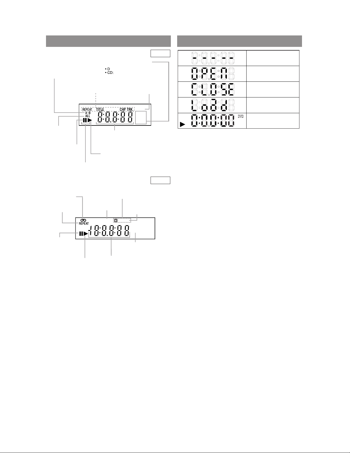
FROM PANEL DISPLAY DISPLAYS DURING OPERATION
Lights up when the inserted
disc is being played back.
Displays a type of the disc
which is inserted on the tray.
VD: DVD disc
Audio CD, MP3, JPEG
Lights up when the
inserted disc comes
to a pause.
Lights up when the
A-B repeat function
is on.
Lights up when the
repeat function is on.
Lights up when playing back
in slow mode. (DVD)
Displays how long the current title
or track has been played back. When
a chapter or track is switched, the
number of a new title, chapter or
track is displayed.
Lights up when
the ALL repeat
function is on.
GROUP P .SCAN
DVD
CD
Lights up when the
progressive scan
system is activated.
Lights up when the inserted
cassette is being played
back.
Lights up when
the playback is
in still or slow mode.
Lights up during
playback when
the repeat function
is on.
Works as a tape counter(hour,minute,second).
Also displays a channel number,
tape speed, remaining time for OTR or
current time.
VCR REC
PM
Lights up
when a tape is
in the DVD/VCR.
Lights up when
the DVD/VCR is
in VCR position.
This light does not
appear when the
DVD/VCR is in
TV position.
Lights up during a recording.
Flashes when a recording
is paused.
Lights up when
current time is P.M.
Lights up when
the timer recording or an
OTR recording has been set.
No disc inserted or
cannot read the disc
Tray open
Tray closed
Loading the Disc
When a disc is being
Play back
DVD
VCR
2-10
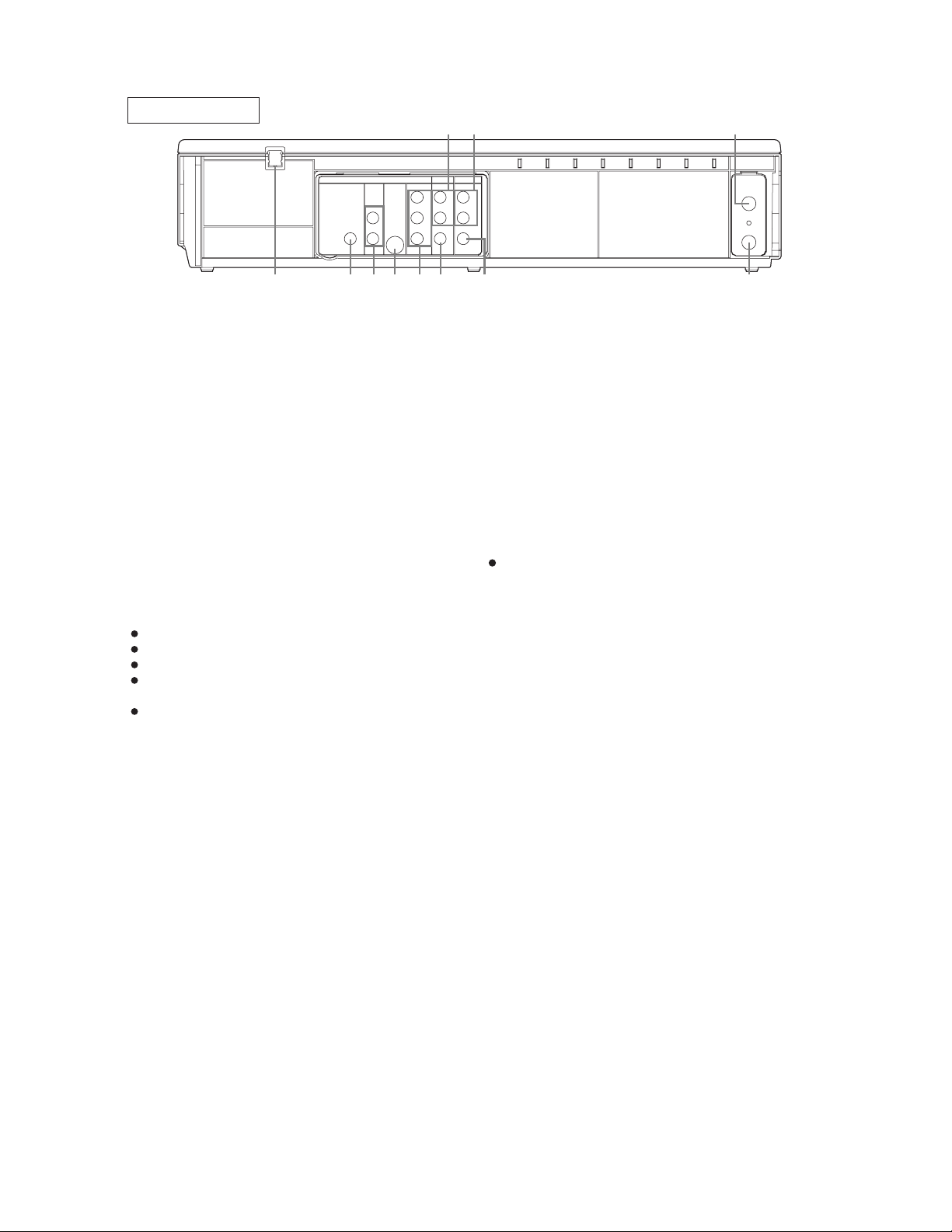
C
he
DIGITAL
AUDIO OUT
COAXIAL
AUDIO
OUT
DVD VCR
DVD/VCR
S-VIDEO
OUT
AUDIO OUT
COMPONENT
VIDEO OUT
AUDIO IN
VIDEO OUT
LY
C
B/
PB
CR/
PR
R
L
R
L
R
ANT-IN
ANT-OUT
VIDEO IN
0VM204468
1 2 3 8 9 1154
6 7 10
ks
e.
to
a
ce
ct
ck
-
D
REAR VIEW
1. AC Power Cord
Connect to a standard AC outlet to supply power to the
DVD/VCR.
2. COAXIAL Jack (DVD only)
Use coaxial digital audio out to connect to a compatible Dolby Digital receiver. Use to connect to a
Dolby Digital decoder or DTS decoder.
3. DVD AUDIO OUT Jacks (DVD only)
Connect the supplied audio cables here and to the Audio
In jacks of a television or other audio equipment (DVD
only).
4. S-VIDEO OUT Jack (DVD only)
Connect an optional S-Video cable here and to the SVideo In jack of a television.
5. COMPONENT VIDEO OUT Jacks (DVD only)
Connect optional component video cables here and to
the component Video In jacks of a television.
6. DVD/VCR AUDIO OUT Jacks
Connect the supplied audio cables here and to the Audio
In jacks of a television or other audio equipment.
7. AUDIO IN Jacks (VCR only)
Connect audio cables coming from the audio out jac
of a camcorder, another VCR, or an audio source her
8. DVD/VCR VIDEO OUT Jack
Connect the yellow video cable (supplied) here and
the TV’s Video In jack.
9. VIDEO IN Jack (VCR only)
Connect a cable coming from the video out jack of
camcorder, another VCR, or an audio-visual sour
(laser disc player, video disc player, etc.) here.
10. ANT-IN (Antenna In) Jack
Connect your antenna, RF INPUT Cable Box, or Dire
Broadcast System.
11. ANT-OUT (Antenna Out) Jack
Use the supplied RF coaxial cable to connect this ja
to the ANTENNAIN Jack on your TV.
Notes
The S-VIDEO OUT jack, COAXIAL jack and COM
PONENT VIDEO OUT jack are only useful in DV
mode.
AUTION:
Be sure to turn off the DVD/VCR and equipment to be connected before connecting.
Read through the operation manual for the equipment to be connected.
Be sure that the colors of the jacks and plugs match up when using VIDEO/AUDIO cables.
Be sure to keep the DVD/VCR connection cables separate from the TV antenna cable when you install t
DVD/VCR, because it may cause electrical interference when you are watching television programs.
DTS audio cannot be produced with an analogue connection.
2-11
3
MAINTENANCE AND INSPECTION
3-1 TROUBLESHOOTING
Troubleshooting is how to service for the specifying malfunction or poor parts.
Detect malfunction or poor parts and service as the following charts.
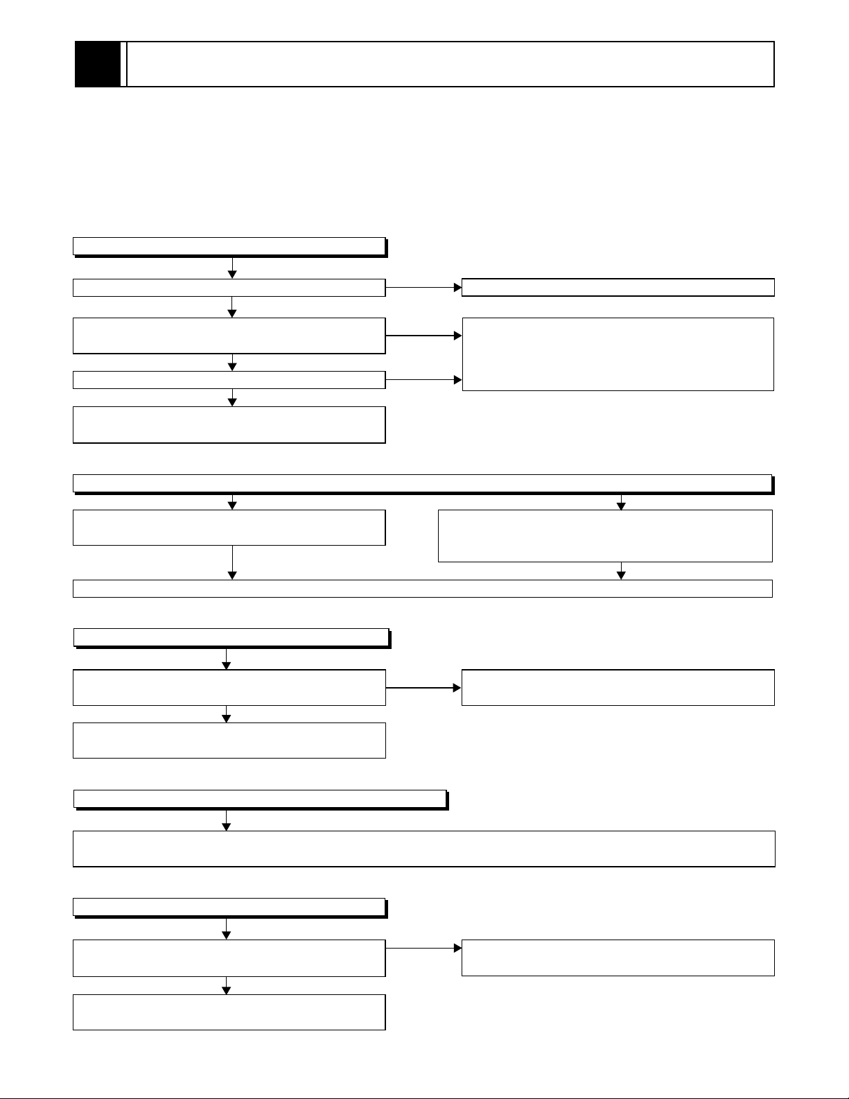
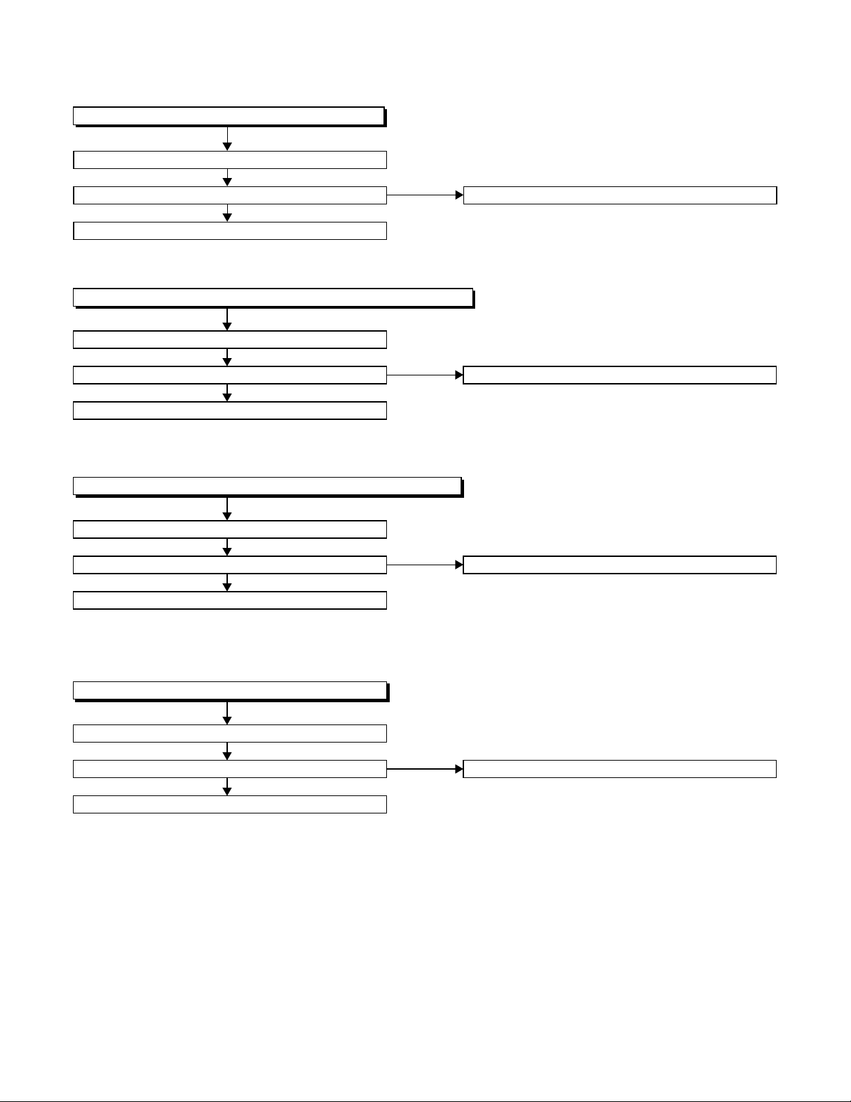
3-1-1 Power Supply Section
FLOW CHART NO.1
The power cannot be turned on.
Is the fuse normal?
Ye s
Is normal state restored when once unplugged
power cord is plugged again after several seconds.
Ye s
Is the AL+5V line voltage normal?
Ye s
Check each rectifying circuit of secondary circuit
and service it if defective.
FLOW CHART NO.2
The fuse blows out.
Check the presence that the primary component
is leaking or shorted and service it if defective.
After servicing, replace the fuse.
FLOW CHART NO.3
When the output voltage fluctuates.
Does the secondary side photo coupler circuit
operate normally?
Ye s
Check the circuit and service it if defective.
(IC1001, D1012, D1024)
No
No
No
No
See FLOW CHART No.2 <The fuse blows out.>
Check for lead or shor-circuiting of primary
circuit component and service it if defective.
(Q1001,Q1003,T001,D1001,D1002,D1003,
D1004,D1011,C1003,C1005)
Check the presence that the rectifying diode or circuit
is shorted in each rectifying circuit of secondary side
and service it if defective.
Check the circuit and service it if defective.
(IC1001, Q031, D031)
FLOW CHART NO.4
When buzz sound can be heard in the vicinity of power circuit.
Check if there is short circuit on the rectifying diode and the circuit in each rectifying circuit of secondary side and
service it if defective.
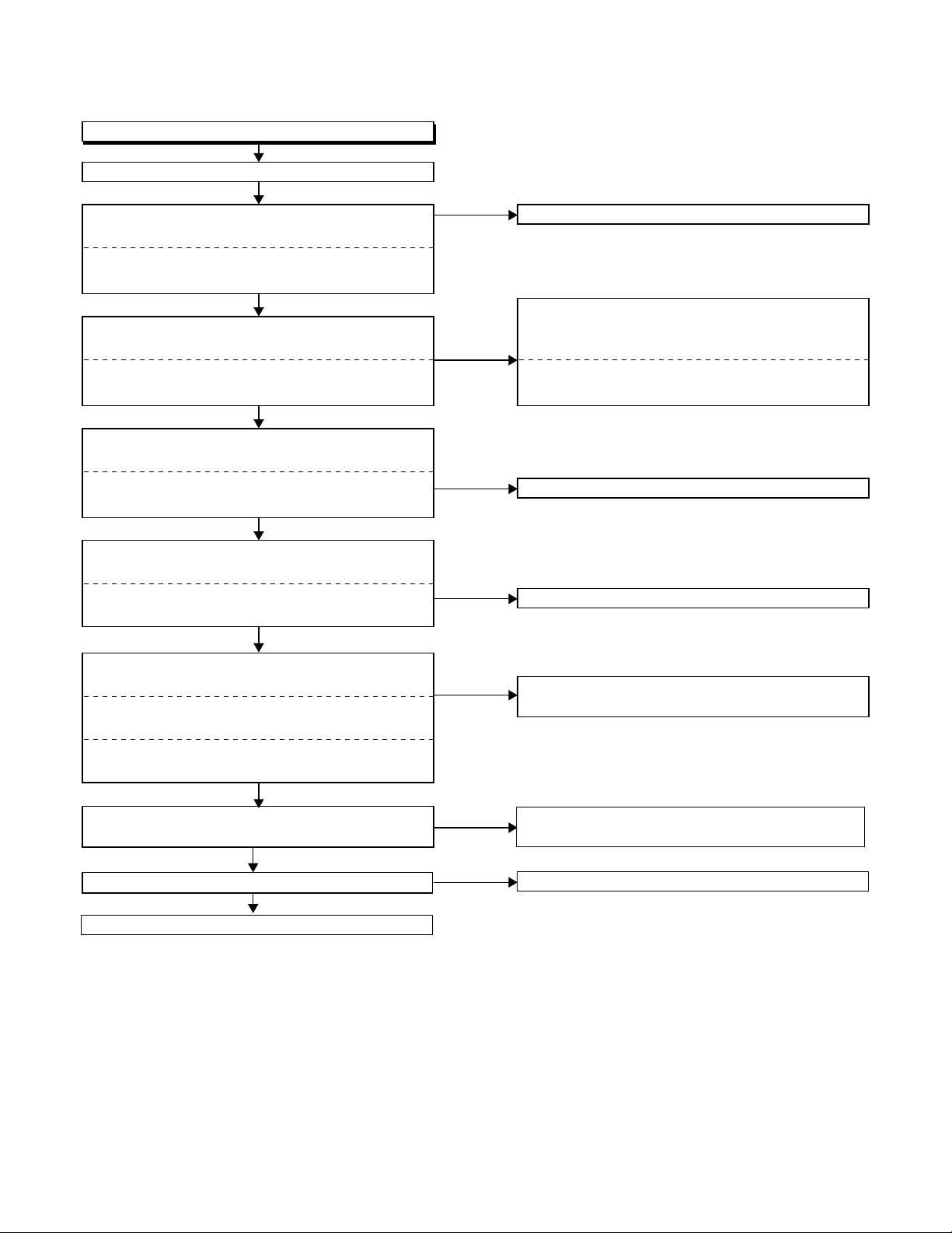
FLOW CHART NO.5
-FL is not outputted.
Is the supply voltage of -30V fed to the anode of
D1010?
Check for load circuit short-circuiting or leak, and
service it if defective.
(D013,D015,D016,D1008,D1010,D1016,D1020,IC1002,IC1004,Q055,Q056,Q057,Q1004,Q1006,Q1011)
No
Check D1010 and their periphery, and service it if
defective.
Ye s
3-1

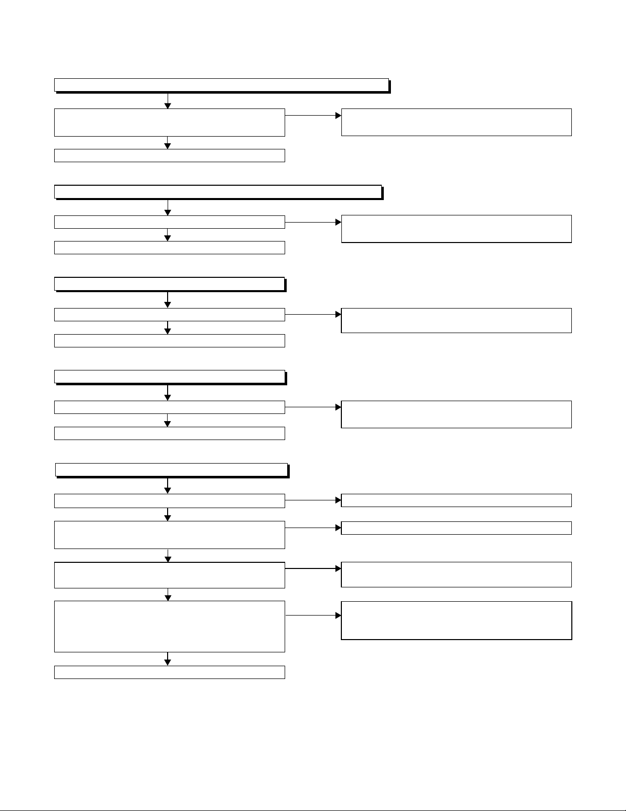
FLOW CHART NO.6
P-ON+9V is not outputted. (AL+5V is outputted normally.)
Is 12V voltage supplied to the collector of Q055?
Ye s
Is the "L" pulse inputted to the base of Q052?
Ye s
Check Q052, D052 and their periphery, and
service it if defective.
FLOW CHART NO.7
P-ON+5V is not outputted. (P-ON+9V is outputted normally.)
Is 5V voltage supplied to the collector of Q056?
Ye s
Is the "H" pulse inputted into the base of Q056?
Ye s
Replace Q056.
FLOW CHART NO.8
TIMER+5V is not outputted. (AL+5V is outputted normally.)
Is the "H" pulse inputted to the base of Q057?
Ye s
Replace Q057.
No
No
No
No
No
Check D015, D031, C018, and their periphery,
and service it if defective.
Replace IC501.
Check D016, L009, C020, C021, and their
periphery, and service it if defective.
Check Q056, R057 and their periphery, and
service it if defective.
Check D030, C017 and their periphery,
and service it if defective.
FLOW CHART NO.9
AL+33V is not outputted.
Is the supply voltage 44V fed the cathode of D013?
Ye s
Check D701, R702, and service it if defective.
FLOW CHART NO.10
AL+18V is not outputted.
Is the supply voltage 44V fed the cathode of D013?
Ye s
Check D504, R092, R095, and service it if defective.
FLOW CHART NO.11
DVD-P-ON+12V is not outputted.
Is 12V voltage supplied to the emitter of Q1006?
Ye s
Is the "L" pulse (approximately 0V) outputted to
the collector of Q1005?
Ye s
Replace Q1006.
No
No
No
No
Check D013, C013 and their periphery, and
service it if defective.
Check D013, C013 and their periphery, and
service it if defective.
Check D015, D031, C018 and their periphery,
and service it if defective.
Check Q1005 and PWRCON line, and service it if
defective.
3-2
FLOW CHART NO.12
DVD-P-ON+3.3V is not outputted. (DVD-P-ON+12V is outputted normally.)
Is the "H" pulse (approximately 5V) inputted into
the base of Q1011?
Ye s
Replace Q1011.
FLOW CHART NO.13
DVD-P-ON+5V is not outputted. (DVD-P-ON+12V is outputted normally.)
Is the "H" pulse inputted to the base of Q1004?
Ye s
Replace Q1004.
FLOW CHART NO.14
EV+1.2V is not outputted.
Is 2.8V voltage supplied to Pin(1) of IC1002?
Ye s
Replace IC1002.
FLOW CHART NO.15
EV+3.3V is not outputted.
Is 4V voltage supplied to Pin(1) of IC1004?
Ye s
Replace IC1004.
No
No
No
No
Check R1077 and their periphery, and service it if
defective.
Check R1068 and their periphery, and service it if
defective.
Check D1020,C1014,L1020, C1015, and their
periphery, and service it if defective.
Check D1008, C1007, L1007, C1038 and their
periphery, and service it if defective.
FLOW CHART NO.16
The fluorescent display tube does not light up.
Is 3.3V voltage supplied to Pin(6, 24) of IC571?
Ye s
Is approximately -24V to -28V voltage supplied to
Pin(15) of IC571?
Ye s
Is there approximately 500kHz oscillation to
Pin(26) of IC571?
Ye s
Are the filament voltage applied between (1, 2)
and (29, 30) of the fluorescent display tube?
Also negative voltage applied between these pins
and GND?
Ye s
Replace the fluorescent display tube.
No
No
No
No
Check the EV+3.3V line and service it if defective.
Check the -FL line and service it if defective.
Check R572, IC571 and their periphery, and
service it if defective.
Check the power circuit, D1016, D1017,
R1042, C1018 and their periphery, and
service it if defective.
3-3

3-1-2 DVD Section
FLOW CHART NO.1
The key operation is not functioning.
Are the contact point and the installation state of
the key switches (SW2001-2003) normal?
Ye s
When pressing each key switches (SW2001,
SW2002, SW2003), do the voltage of each pin
of CN1001 (shown below) change to "H" (3.3V)
from "L" (0V)?
SW2001 → CN1001 24PIN
SW2002 → CN1001 26PIN
SW2003 → CN1001 25PIN
Ye s
Replace DVD Main CBA.
FLOW CHART NO.2
No DVD operation is possible from the remote control unit. (
Is 5V voltage supplied to Pin(3) terminal of the
RM2001 (remote control receiver)?
Ye s
Is the "L" pulse sent out from Pin(1) terminal of the
RM2001 (remote control receiver) when the remote
control unit is activated?
Ye s
Is the "L" pulse signal supplied to Pin(22) of
CN1001?
Ye s
Replace the DVD Main CBA.
No
No
No
No
No
Re-install the key switches (SW2001, SW2002,
SW2003) correctly or replace the poor switch.
Check the key switches (SW2001, SW2002,
SW2003) and their periphery, and service it if
defective.
Operation is possible from the unit.)
Check AL+5V line, and service it if defective.
Replace the RM2001 (remote control receiver).
Replace remote control unit if needed.
Check the line between the RM2001 (remote
control receiver) and Pin(22) of CN1001, and
service it if defective.
FLOW CHART NO.3
The disc tray cannot be opened and closed. (It can be done using the remote control unit.)
Does the voltage of Pin(24) on CN1001 become
to 3.3V from 0V when pressing "OPEN/CLOSE"
button on the unit?
Ye s
Refer to "FLOW CHAR NO.4" <The disc tray
cannot be opened and closed.>
FLOW CHART NO.4
The disc tray cannot be opened and closed.
Replace the DVD Main CBA.
No improvement can be found.
Ye s
Replace the DVD Mechanism.
No
No
Replace the "OPEN/CLOSE" button (SW2001).
Original DVD Main CBA is poor.
3-4
FLOW CHART NO.5
The [No Disc] indication. (In case of focus error)
Replace the DVD Main CBA.
No improvement can be found.
Ye s
Replace the DVD Mechanism.
FLOW CHART NO.6
The [No Disc] indication. (In case focus servo does not function.)
Replace the DVD Main CBA.
No improvement can be found.
Ye s
Replace the DVD Mechanism.
FLOW CHART NO.7
The [No Disc] indication. (When the laser beam does not light.)
Replace the DVD Main CBA.
No improvement can be found.
Ye s
Replace the DVD Mechanism.
No
No
No
Original DVD Main CBA is poor.
Original DVD Main CBA is poor.
Original DVD Main CBA is poor.
FLOW CHART NO.8
Both picture and sound do not operate normally.
Replace the DVD Main CBA.
No improvement can be found.
Ye s
Replace the DVD Mechanism.
No
Original DVD Main CBA is poor.
3-5

FLOW CHART NO.9
Picture does not appear normally.
Set the disc on the disc tray, and playback.
Are the video signals outputted to each pin of
CN1601 on the Main CBA?
CN1601 8PIN S-Y(I/P)
CN1601 10PIN S-C
CN1601 6PIN Pb/Cb
CN1601 4PIN Pr/Cr
CN1601 1PIN S-Y(I)
Ye s
Are the video signals shown above inputted into
each pin of IC1402 and IC1403?
IC1402 3PIN S-Y(I/P)
IC1403 1PIN S-C
IC1402 6PIN Pb/Cb
IC1402 8PIN Pr/Cr
IC1403 3PIN S-Y(I)
Ye s
Are the video signals outputted to each pin
of IC1402 and IC1403?
IC1403 6PIN CVBS
IC1402 13PIN S-Y(I/P)
IC1403 7PIN S-C
IC1402 11PIN Pb/Cb
IC1402 10PIN Pr/Cr
IC1403 5PIN S-Y(I)
Ye s
Are the video signals outputted to the specific
output terminal?
Are the luminance signals outputted to the
S-OUT terminal (JK1401)?
Are the chroma signals outputted to the
S-OUT terminal (JK1401)?
Are the component video signals outputted to the
VIDEO OUT terminal (JK1403)?
Are the composite video signals outputted to
the VIDEO OUT terminal (JK751)?
No
No
No
No
No
No
No
Replace the DVD Main CBA or the DVD
Mecha.
Check the line between each pin of CN1601 and
each pin of IC1402 and IC1403 on the Main CBA,
and service it if defective.
CN1601 8PIN → IC1402 3PIN S-Y(I/P)
CN1601 10PIN → IC1403 1PIN S-C
CN1601 6PIN → IC1402 6PIN Pb/Cb
CN1601 4PIN → IC1402 8PIN Pr/Cr
CN1601 1PIN → IC1403 3PIN S-Y(I)
Check DVD-P-ON+5V line and service it if defective.
No
Is 5V voltage applied to the Pin(4, 12) of
IC1402 and Pin(4) of IC1403?
Ye s
Replace IC1402 or IC1403?
Check the periphery of JK1401 from
Pin (5) of IC1403 and service it if defective.
Check the periphery of JK1401 from
Pin (7) of IC1403 and service it if defective.
Check the periphery of JK1403 from Pins (10, 11,
13) of IC1402 and service it if defective.
No
Are the composite video signals outputted to
Pin(15) of IC751?
No
Are the "L" pulse inputted into Pins(9,10,11) of IC751?
No
Replace IC501.
Ye s
Ye s
Check the line between Pin(15) of IC751 and JK751
and service it if defective.
Replace IC751.
3-6
FLOW CHART NO.10
Audio is not outputted.
Set the disc on the disc tray, and playback.
Are the analog audio signals outputted to each pin
of CN1601 on Main CBA?
CN1601 14PIN AUDIO-L
CN1601 16PIN AUDIO-R
Ye s
Are the analog audio signals inputted to each pin
of IC1201.
IC1201 2PIN AUDIO-L
IC1201 6PIN AUDIO-R
Ye s
Is the "H" level mute signals outputted to CN1601
on the Main CBA ?
CN1601 13PIN DVD A-MUTE
CN1601 15PIN DVD A-R-MUTE
Ye s
Are the analog audio signals inputted to each pin
of IC1201?
IC1201 1PIN AUDIO-L
IC1201 7PIN AUDIO-R
Ye s
Are the audio signals outputted to the specific
output terminal?
Are the audio signals outputted to the L/R OUT
terminal (JK756)?
Are the audio signals outputted to the L/R OUT
terminal (JK751)?
No
Are the audio signals outputted to Pin(4,14) of
IC751?
No
Are the "L" pulse inputted into Pins(9,10,11) of IC751?
Ye s
Replace IC751.
No
No
No
No
No
Ye s
No
Replace the DVD Main CBA or the DVD Mecha.
Check each line between each pin of CN1601
and each pin of IC1201 on Main CBA, and service
it if defective.
CN1601 14PIN → IC1201 2PIN AUDIO-L
CN1601 16PIN → IC1201 6PIN AUDIO-R
Replace the DVD Main CBA or the DVD Mecha.
Replace IC1201.
Check the periphery between Pins(1,7) of IC1201
and JK756, and service it if defective.
Check the line between Pin(
and their periphery, and service it if defective.
Replace IC501.
4,14
) of IC751 and JK751
,
3-7
3-1-3 VCR Section
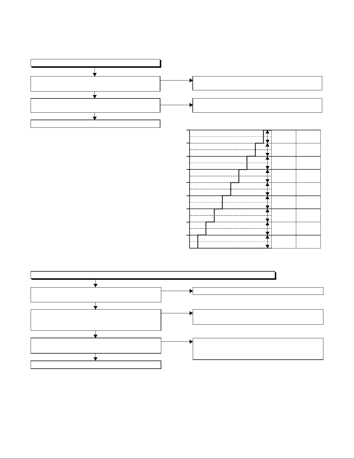
FLOW CHART NO.1
The key operation is not functioning.
Are the contact point and the installation state of
the key switches normal?
Ye s
Is the control voltage normally inputted into
Pins(66,67) of IC501?
Ye s
Replace IC501.
No
Re-install some key switches correctly or
replace some key switches.
No
Check the key switches and their periphery, and
service it if defective.
Terminal voltage of IC501-66,67
4.30
3.60
2.90
2.39
1.98
1.61
1.27
0.92
0.51
(V)
KEY-1
IC501-67
-----
-----
-----
REC
PLAY
STOP
/EJECT
FF
REW
POWER
KEY-2
IC501-66
-----
-----
-----
-----
-----
S-INH
CH
DOWN
CH UP
DVD/VCR
SELECT
FLOW CHART NO.2
No VCR operation is possible from the remote control unit. (
Is 5V voltage supplied to the Pin(3) terminal of
No
the RM2001 (remote control receiver)?
Ye s
Is the "L" pulse sent out from Pin(1) terminal of
No
the RM2001 (remote control receiver) when the
remote control unit is activated?
Ye s
No
Is the "L" pulse signal supplied to the Pin(5) of
IC501?
Ye s
Replace IC501.
Operation is possible from the unit.)
Check AL+5V line and service it if defective.
Replace the RM2001 (remote control receiver).
Or replace remote control unit.
Check the line between the RM2001 (remote
control receiver) and the Pin(5) of IC501, and
service it if defective.
3-8

FLOW CHART NO.3
Cassette tape can not be loaded.
When loading a cassette tape, on Pin(69) of
IC501, does the "L" pulse switch to the "H" pulse?
Ye s
When loading a cassette tape, is the specified
voltage (approximately 13V) outputted to the
terminal of the Loading Motor Unit?
Ye s
Replace the Loading Motor Unit.
FLOW CHART NO.4
Cassette tape is ejected right after the loading.
When loading a cassette tape, on Pin(69) of IC501,
does the "L" pulse switch to the "H" pulse?
Ye s
When loading a cassette tape, on Pin(62) of IC501,
does the "L" pulse switch to the "H" pulse?
Ye s
When loading a cassette tape, does the LD-SW
operate normally?
Ye s
Replace IC501.
No
No
No
No
No
Check the line between the start sensor and
Pin(69) of IC501, and service it if defective.
Replace the Capstan Motor Unit.
Check the line between the start sensor and
Pin(69) of IC501, and service it if defective.
Check the line between the end sensor and
Pin(62) of IC501, and service it if defective.
Check the line between the LD-SW(SW512) and
Pin(68) of IC501, and service it if defective.
FLOW CHART NO.5
Cassette tape can not be ejected.
When pressing the eject button, does the Capstan
Motor start rotating?
Ye s
While the Capstan Motor is rotating, is the Takeup
Reel rotating?
Ye s
While the Takeup Reel is rotating, is the reel pulse
signal inputted to Pin(3) of IC501?
Ye s
While the reel pulse signal is inputting, is "L" pulse
inputted to Pin(21) of IC501?
Ye s
Is the specified voltage (approximately 13V)
outputted to the terminal of the Lading Motor Unit?
Ye s
Is the Loading Motor rotating?
Ye s
Check the Cassette Cam or Cassette Gear, etc,
and service it if defective.
No
No
No
No
No
No
Refer to "FLOW CHART NO.6 " <The Capstan
Motor does not rotate>.
Check the Reel Disc or Reel Drive Unit, and
service it if defective.
Check the line between the Takeup Reel sensor
and Pin(3) of IC501, and service it if defective.
Replace IC501.
Replace the Capstan Motor unit.
Replace the Loading Motor unit.
3-9
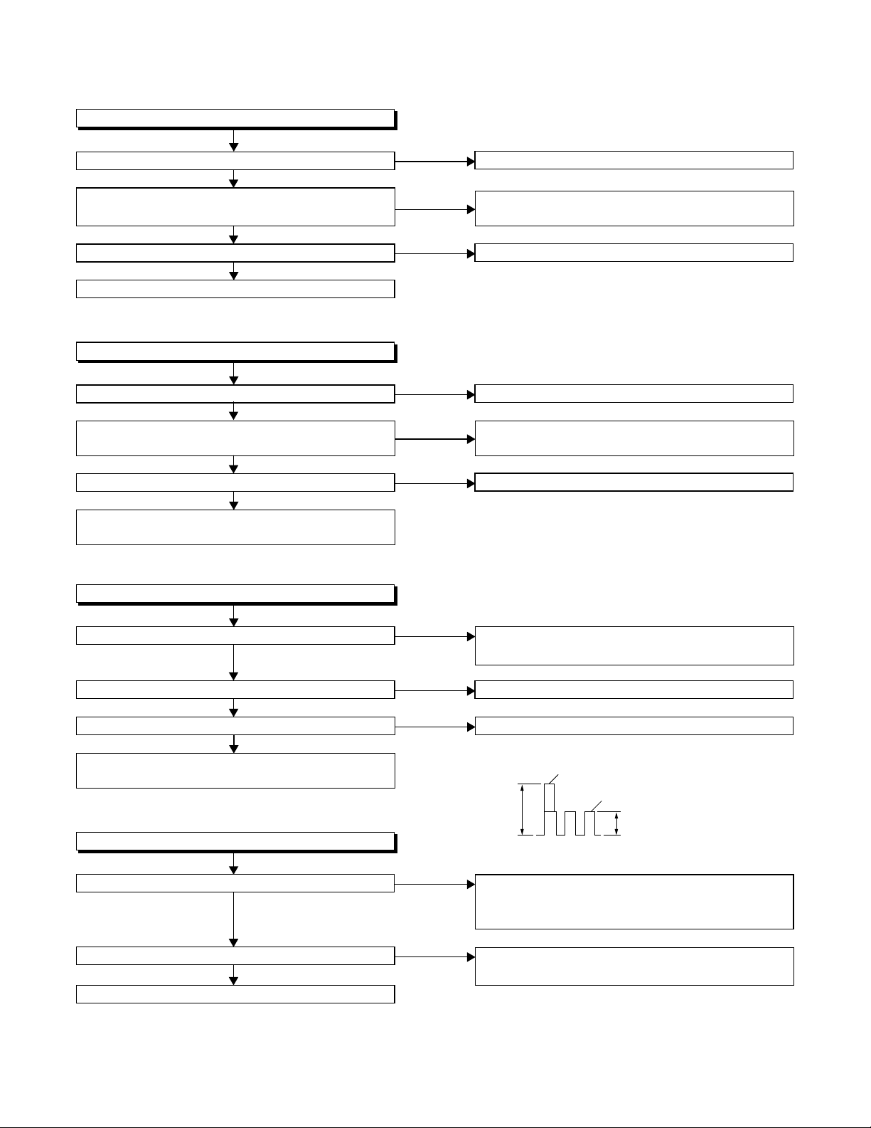
FLOW CHART NO.6
Capstan Motor does not rotate.
Is 5V voltage supplied to Pin(2) of CN502?
Ye s
Is over approximately 2.6V voltage supplied to
Pin(5) of CN502?
Ye s
Is 12V voltage supplied to Pins(1,11) of CN502?
Ye s
Replace the Capstan Motor Unit.
FLOW CHART NO.7
Drum Motor does not rotate.
Is 5V voltage supplied to Pin(2) of CN502?
Ye s
Is over approximately 2.6V voltage supplied to
Pin(8) of CN502?
Ye s
Is 12V voltage supplied at Pin(1,11) of CN502?
Ye s
Replace the Capstan Motor Unit or Cylinder
Assembly.
No
No
No
No
No
No
Check the P-ON+5V line and service it if detective.
Check the line between Pin(5) of CN502 and
Pin(28) of IC501, and service it if detective.
Check the AL+12V line and service it if detective.
Check the P-ON+5V line and service it if detective.
Check the line between Pin(8) of CN502 and
Pin(29) of IC501, and service it if detective.
Check the AL+12V line and service it if detective.
FLOW CHART NO.8
Drum Motor rotates only for a few seconds.
Is the drum PG/FG signal inputted to Pin(47) of IC501?
Ye s
Is the RF-SW signal outputted to Pin(18) of IC501?
Ye s
Is 12V voltage supplied Pin(1,11) of CN502?
No
No
No
Ye s
Replace the Capstan Motor Unit or the Cylinder
Assembly.
FLOW CHART NO.9
RF-SW signal is not outputted.
No
Is the Drum Motor rotating?
Ye s
Is the drum PG/FG signal inputted to Pin(47) of IC501?
No
Ye s
Replace IC501.
Replace the Capstan Motor Unit or the Cylinder
Assembly.
Replace IC501.
Check the AL+12V line and service it if detective.
D-PG
5Vp-p
D-FG
2.5Vp-p
DRUM PG/FG SIGNAL WAVEFORM
Refer to "FLOW CHART NO.7" <Drum Motor does
not rotate> and "FLOW CHART NO.8" <Drum
Motor rotates only for a few seconds>.
Replace the Capstan Motor Unit or the Cylinder
Assembly.
3-10
 Loading...