

Page 1

ENGLISH
DEUTSCH
FRANÇAIS
ITALIANO
ESPAÑOL
NEDERLANDS
NORSK
TECHNICAL
PORTGÊS
Liquid Crystal Projector
CP-S225W / CP-X275W
USER'S MANUAL
Please read this user's manual thoroughly to ensure correct usage through understanding.
BEDIENUNGSANLEITUNG
Bitte lessen Sie diese Bedienungsanleitung zugunsten der korrekten Bedienung
aufmerksam.
MANUEL D'UTILISATION
Nous vous recommandons de lire attentivement ce manuel pour bien assimiler le
fonctionnement de l'appareil.
MANUALE D'ISTRUZIONI
Vi preghiamo voler leggere attentamente il manuale d'sitruzioni in modo tale da poter
comprendere quanto riportato ai fini di un corretto utilizzo del proiettore.
MANUAL DE USUARIO
Lea cuidadosamente este manual del usuario para poder utilizar corretamente el
producto.
GEBRUIKSAANWIJZING
Lees voor het qebruik alstublieft deze handleiding aandachtig door, om volledig profijt te
hebben van de uitgebreide mogelijkheden.
BRUKERHÅNDBOK
Vennligst les denne bruksanvisningen grundig for å være garantert driftssikker bruk.
INSTRUÇÕES DO PROPRIETÁRIO
Para assegurar o uso correto do equipamento, por favor leia atentamente este manual do
usuário.
TECHNICAL
REGULATORY NOTICES
Page 2

ENGLISH
Liquid Crystal Projector
USER'S MANUAL
USER'S MANUAL
ENGLISH-1
Thank you for purchasing this liquid crystal projector.
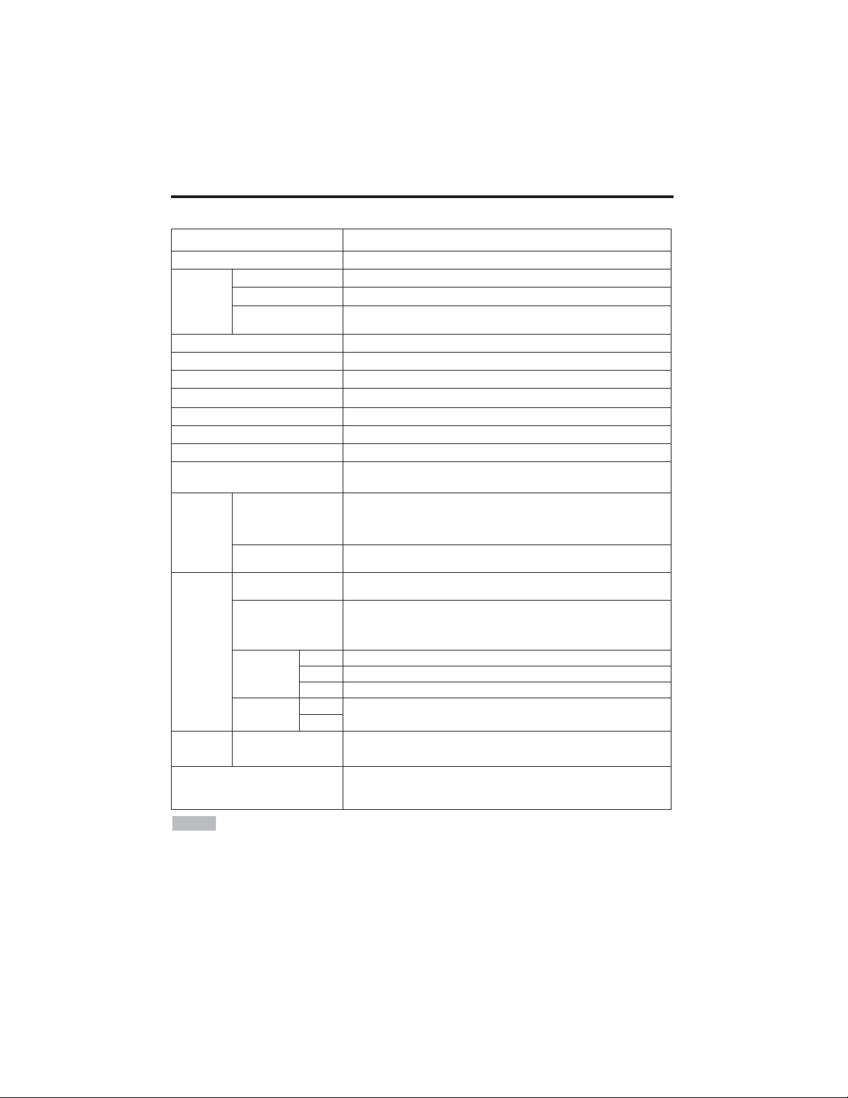
CONTENTS
CONTENTS
Page
FEATURES .......................................2
BEFORE USE ...................................2
Contents of Package ..............................2
Part Names.............................................3
Loading the Battery ................................4
INSTALLATION ................................5
Installation of the Projector and Screen
........5
Angle Adjustment ...................................5
Cabling ...................................................6
Power Connection ..................................7
Example of System Setup ......................7
Plug & Play.............................................7
OPERATIONS...................................8
Power ON ..................................................8
Power OFF
..............................................8
Basic Operation......................................9
Setup Menu ..........................................11
Input Menu............................................12
Image Menu..........................................13
Options Menu .......................................14
No Signal Menu....................................15
MAINTENANCE ..............................16
Lamp.....................................................16
Air Filter ................................................18
Other Maintenance...............................18
Page
TROUBLESHOOTING ....................19
OSD Message ......................................19
Indicators Message ..............................20
Symptom ..............................................21
SPECIFICATIONS...........................22
WARRANTY AND AFTER-SERVICE
......23
.......................................................................................
TABLES
Table 1. Installation Reference.................5
Table 2. Cabling .......................................6
Table 3. Basic Operations ........................9
Table 4. Setup Menu ..............................11
Table 5. Input Menu................................12
Table 6. Image Menu..............................13
Table 7. Options Menu ...........................14
Table 8. No Signal Menu........................15
Table 9. OSD Message ..........................19
Table 10. Indicator Message ..................20
Table 11. Symptom ................................21
Table 12. Specifications .........................22
.......................................................................................
For "TECHNICAL" and "REGULATORY
NOTICE", see the end of this manual.
• The information in this manual is subject to change without notice.
• The manufacturer assumes no responsibility for any errors that may appear in this manual
• The reproduction, transmission or use of this document or contents is not permitted without
express written authority.
TRADEMARK ACKNOWLEDGMENT : PS/2, VGA and XGA are registered trademarks of
International Business Machines Corporation. Apple, Mac and ADB are registered trademarks of
Apple Computer, Inc. VESA and SVGA are trademarks of the Video Electronics Standard
Association. Windows is a registered trademark of Microsoft Corporation. Carefully observe the
trademarks and registered trademarks of all companies, even when not mentioned.
NOTE
WARNING • Please read the accompanying manual “SAFETY
INSTRUCTIONS” and this “USER'S MANUAL” thoroughly to ensure correct
usage through understanding. After reading, store this instruction manual in a
safe place for future reference.
Page 3
ENGLISH-2
FEATURES
FEATURES
This liquid crystal projector is used to project various computer signals as well as NTSC / PAL /
SECAM video signals onto a screen. Little space is required for installation and large images can
easily be realized.
Outstanding Brightness
The UHB lamp and high-efficiency optical system assure a high level of brightness.
Partial Magnification Function
Interesting parts of images can be magnified for closer viewing.
Distortion Correction Function
Distortion-free images are quickly available.
Extra-low Noise Function
Acoustic noise level from the unit can be reduced.
BEFORE USE
BEFORE USE
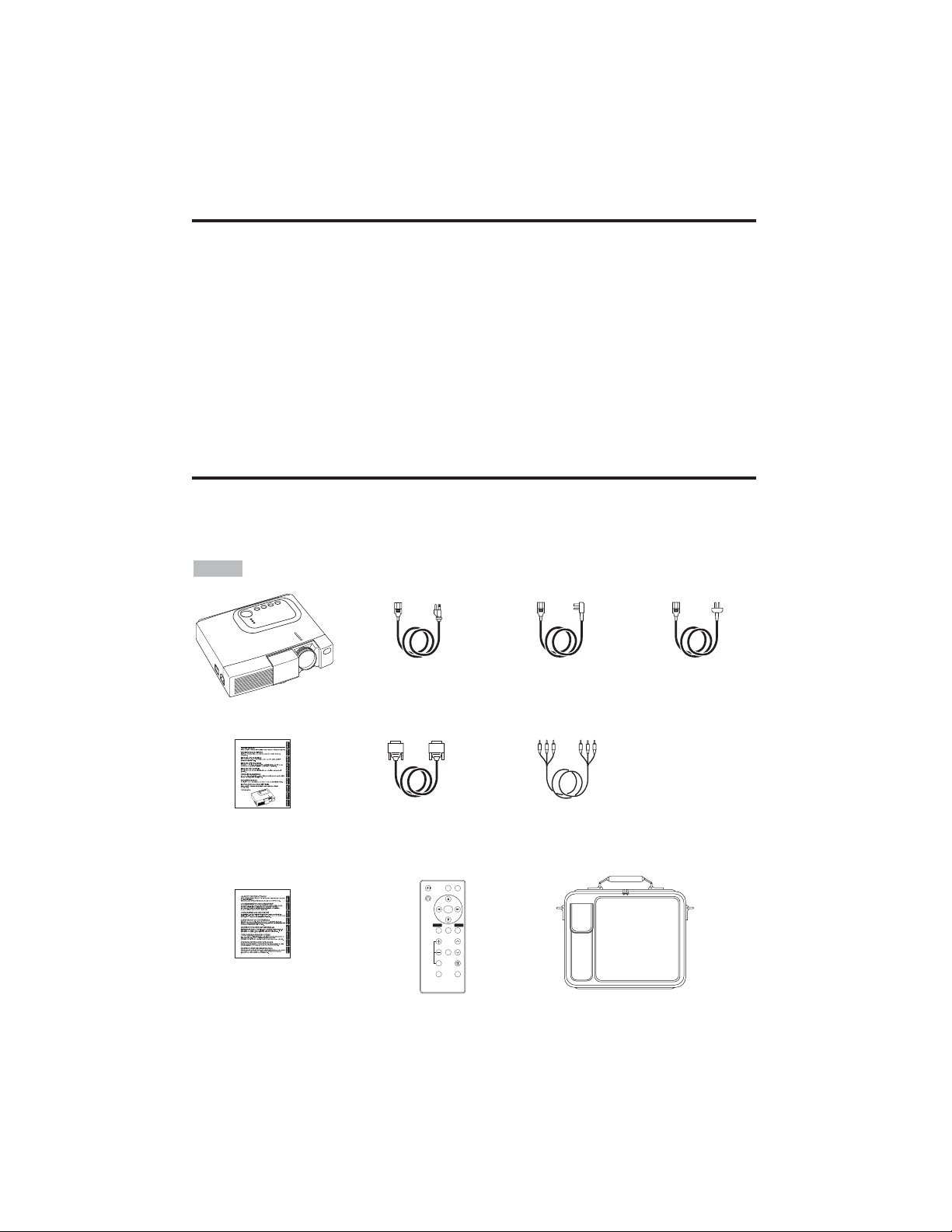
Contents of package
Make sure all of the following items are included in the package. If anything is missing, please
contact your dealer.
• Keep the original packing material for future reshipment.
NOTE
Projector
Safety Instructions
Power Cord
(US Type)
Power Cord
(UK Type)
Power Cord
(Europe Type)
RGB Cable
Component
Video Cable
(with green lead)
Remote Controller
containing Battery
Carrying Bag
User’s Manual
(this manual)
VIDEO
STANDBY/ON
RGB
KEYSTONE
MENU
SELECT
MENU RESET
POSITION
MAGNIFY
FREEZE
VOLUME
MUTE
OFF
AUTO
BLANK
Page 4
ENGLISH-3
BBEEFFOORREEUUSSEE((ccoonnttiinnuueedd)
)
ENGLISH
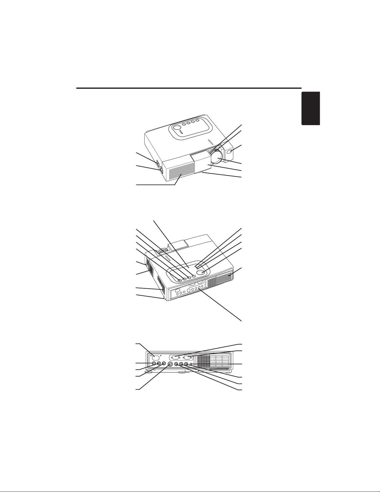
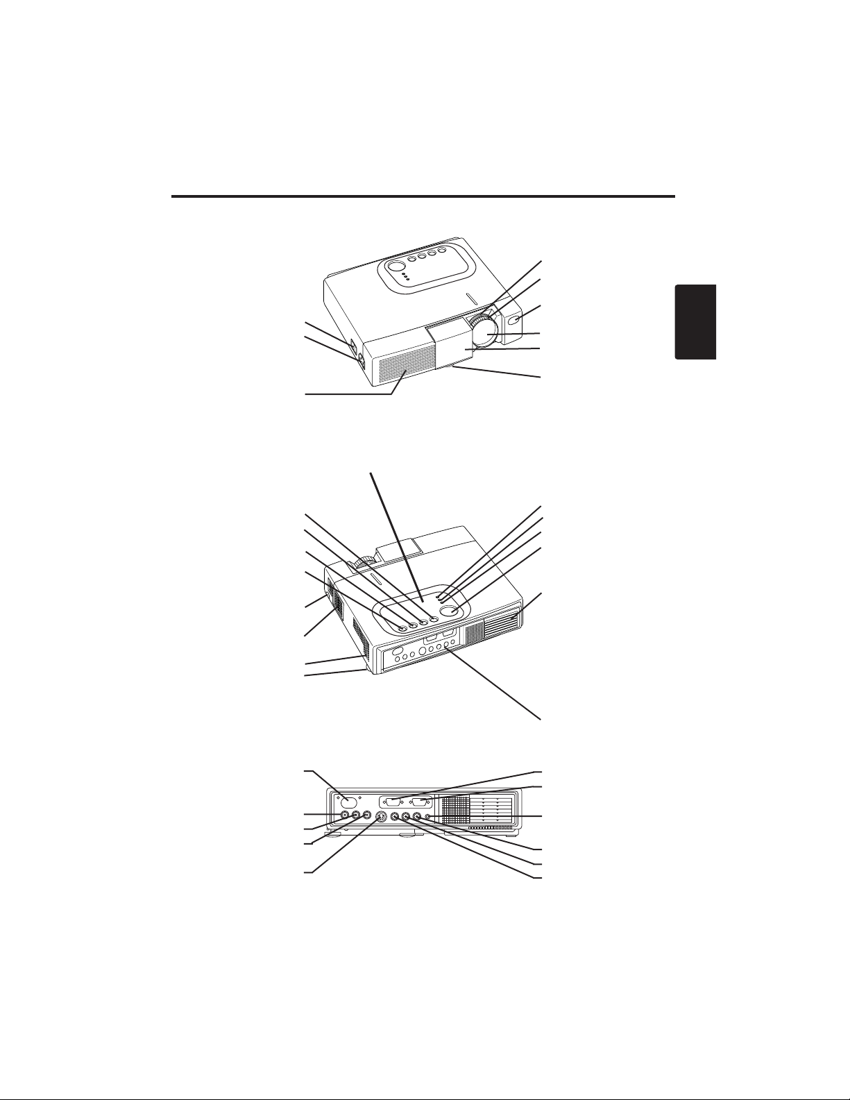
Part Names
Power Switch
AC Inlet
(to the Power Cord)
Ventilation Openings
(Intake)
Zoom Knob
Focus Ring
Remote Control Sensor
Lens
Slide Lens Door
Foot Adjuster
Front / Left View
RESET Button
KEYSTONE Button
INPUT Button
STANDBY/ON Button
Foot Adjuster Button
Air Filter and Intake
(for the Cooling Fan)
Speaker
Rear Foot Adjuster
LAMP Indicator
TEMP Indicator
POWER Indicator
MENU Button
Ventilation Openings
(Exhaust)
Rear / Right View
Terminal Panel
(Refer below)
Remote Control Sensor
COMPONENT
Y Terminal
C
B/PB Terminal
C
R/PR Terminal
S-VIDEO Terminal
RGB Terminal
CONTROL Terminal
AUDIO Terminal
AUDIO
R Terminal
L Terminal
VIDEO Terminal
Terminal Panel
Control Panel (Refer to P.8 "OPERATIONS")
Page 5
ENGLISH-4
BBEEFFOORREEUUSSEE((ccoonnttiinnuueedd)
)
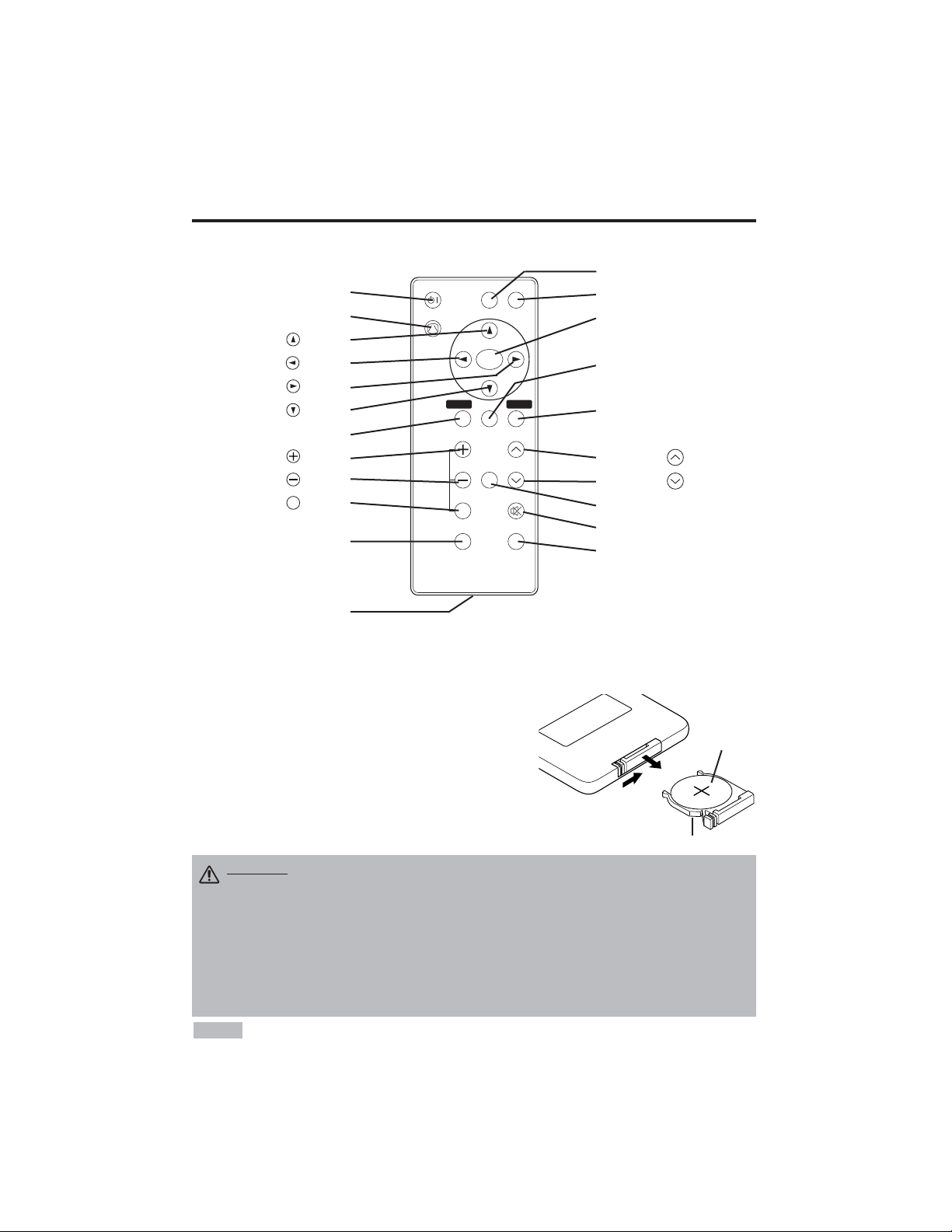
Part Names (continued)
STANDBY/ON
STANDBY/ON Button
KEYSTONE Button
Button
Button
Button
Button
MENU Button
MAGNIFY Button
MAGNIFY Button
MAGNIFY Button
AUTO Button
Battery Holder
OFF
VIDEO Button
RGB Button
MENU SELECT Button
POSITION Button
RESET Button
VOLUME Button
VOLUME Button
FREEZE Button
MUTE Button
BLANK Button
Remote Controller
Loading the Batteries
First Loading:
In original packing, the battery is installed in the battery holder of
the remote controller with protection film(the transparent film some
of which is inside the battery folder). Pull out the protection film to
load the battery.
Replacing:
1. See the reverse side of the remote controller.
2. Pinch the groove and pull out battery holder as the drawing right.
3. Remove the worn battery.
4. Install the new battery with “+” side facing.
5. Push in and click the battery holder.
Pull out
“+” side
Battery Holder
(Refer to Page.8 "OPERATIONS")
Replace the batteries when remote control transmitter operation becomes difficult.
NOTE
CAUTION •
Incorrect handling of the battery could result in fire or personal injury.The
battery may explode if not handled properly. Be careful in handling the battery
according to instructions of accompaning manual "SAFETY INSTRUCTIONS"and this
manual.
• Use the 3V micro lithium battery type no.CR2025 only.
• When loading the battery, make sure the plus and minus terminals are correctly oriented as
indicated in the remote controller.
• When you dispose the battery, you should obey the law in the relative area or country.
• Keep the battery away from children and pets.
• When not to be used for an extended period, remove the battery from the remote controller.
KEYSTONE
VIDEO
MENU
SELECT
RGB
MENU RESET
POSITION
MAGNIFY
FREEZE
OFF
AUTO
VOLUME
MUTE
BLANK
Page 6

ENGLISH-5
ENGLISH
INSTALLATION
INSTALLATION
Installation of the Projector and Screen
Refer to the drawing and table below for determining the screen size and projection distance.
Angle Adjustment
Use the foot adjusters on the bottom of
the projector to adjust the projection
angle. It is variable within 0˚ to 10˚
approximately.
1. Lift up the front side of the projector,
and pressing the foot adjuster button,
adjust the projection angle.
2. Release the button to lock at the
desired angle.
3. Make the rear foot adjuster screw to
adjust the left-right slope.
The projection distances shown in the table below
are for full size (CP-S225W:800 x 600 dots / CPX275W:1024 x 768 dots).
a: Distance from the projector to the screen. (±10%)
b: Distance from the lens center to the bottom of the
screen. (±10%)
Table 1. Installation Reference
Screen
CAUTION • Install the projector in a suitable environment according to
instructions of the accompanying manual “SAFETY INSTRUCTIONS” and this
manual.
• Please basically use liquid crystal projector at the horizontal position.
If you use
liquid crystal projector by the lens up position, the lens down position and the side up
position, this may cause the heat inside to build up and cause damage.
Be especially
careful not to install it with ventilation holes blocked.
• Do not install LCD projector in smoke effected environment. Smoke residue may
buildup on critical parts (i.e.LCD panel, Lens Assy etc.).
CAUTION • Do not release the foot adjuster button unless the projector is
being held; otherwise, the projector could overturn or fingers could get
caught and cause personal injury.
TOP VIEW
SIDE VIEW
a
b
Foot Adjuster
Press the foot adjuster button
Rear Foot Adjuster
Lens
center
Screen size
[inches (m)]
a [inches (m)]
b
[inches (cm)]
Min. Max.
40 (1.0) 37 (0.9) 46 (1.2) 3 (8.7)
60 (1.5) 57 (1.5) 69 (1.8) 5 (13.1)
80 (2.0) 77 (1.9) 93 (2.4) 7 (17.4)
100 (2.5) 96 (2.4) 116 (2.9) 9 (21.8)
120 (3.0) 116 (2.9) 139 (3.5) 10 (26.1)
150 (3.8) 145 (3.7) 174 (4.4) 13 (32.7)
200 (5.0) 194 (4.9) 233 (5.9) 17 (43.5)
Page 7
ENGLISH-6
IINNSSTTAALLLLAATTIIOONN((ccoonnttiinnuueedd)
)
• Before connecting, read instruction manuals of the devices to be connected, and make sure that the
projector is compatible with the device.
• Secure the screws on the connectors and tighten.
• For some RGB input modes, the optional Mac adapter is necessary.
• To select the digital RGB input, the comuter may need some settings. See the manuals of the computer for
details.
• Some computers may have multiple display screen modes. Use of some of these modes will not be possible
with this projector.
• Refer to the “TECHNICAL” section for the pin assign ment of connectors.
• Refer to manual of the optional RS-232C cable, for the communication data.
• For others, consult your dealer.
NOTE
CAUTION • Incorrect connecting could result in fire or electrical shock.
Please read this manual and the separate “SAFETY INSTRUCTIONS”.
• Before connecting, turn off to all devices to be connected, except for the USB
cable.
• The cables may have to be used with the core set to the projector side. Use the
cables which are included with the projector or specified.
Cabling
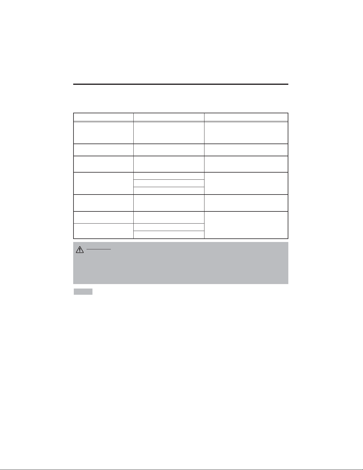
Refer to the table below for connecting each terminal of the projector to a device.
Table 2. Cabling
Function Terminal Cable
Analog RGB input RGB
Accessory RGB cable or optional RGB
cable with D-sub 15-pin shrink jack and
inch thread screws
RS-232C communication CONTROL Optional RS-232C cable
Audio input
(from the computer)
AUDIO Optional audio cable with stereo mini jack
Component video input
COMPONENT VIDEO Y
Accessory component video cable
COMPONENT VIDEO CB/PB
COMPONENT VIDEO CR/PR
S-video input S-VIDEO
Optional S-video cable with mini DIN 4-pin
jack
Video input VIDEO
Optional video/audio cable with RCA jack
Audio input
(from video equipment)
AUDIO L
AUDIO R
Page 8
ENGLISH-7
ENGLISH
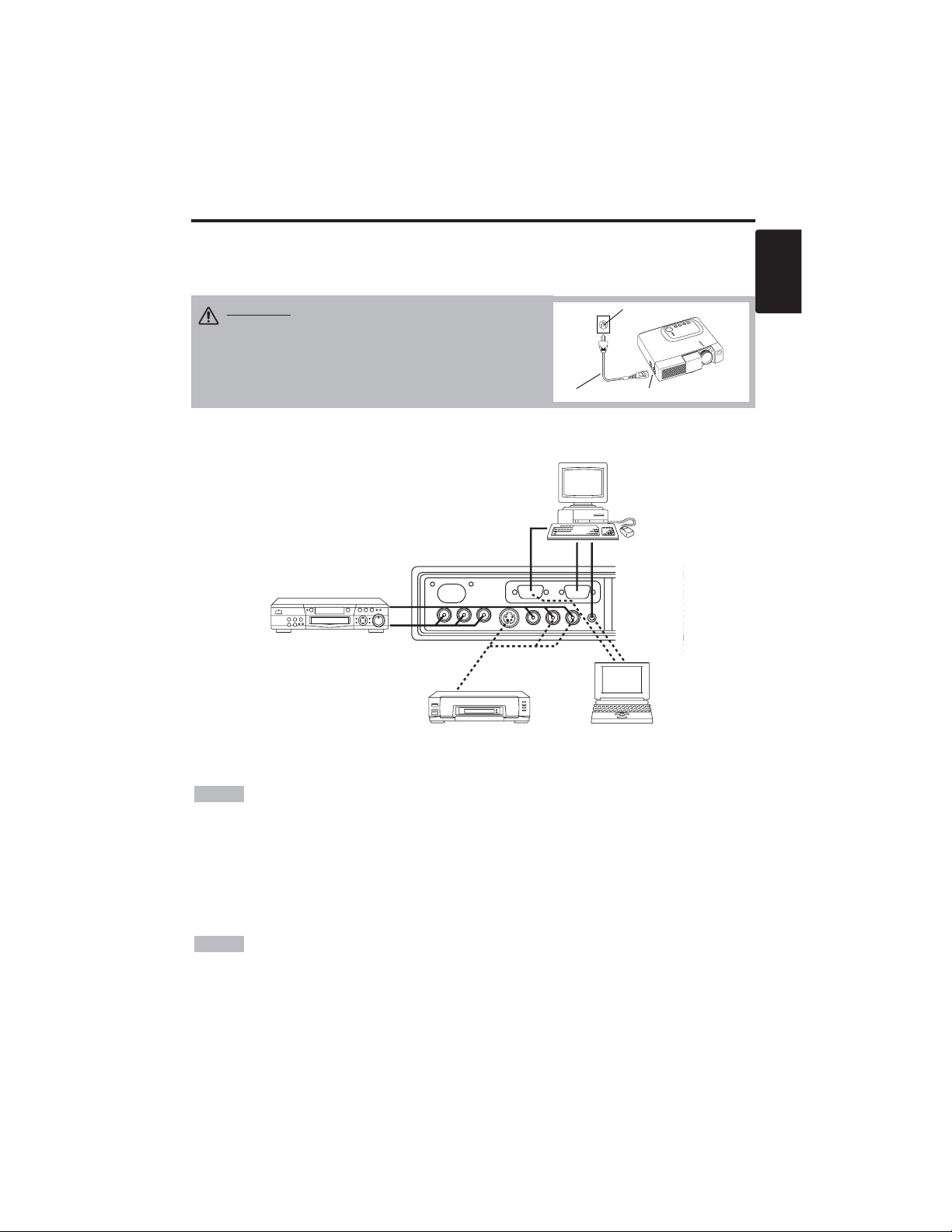
Example of system setup
S-Video Tape
Recorder
Computer
(notebook type)
• When connecting with a notebook computer, set the proper RGB external image output
(setting CRT display or simultaneous display of LCD and CRT). Please read instruction manual of
the notebook for more information.
Plug & Play
This projector is VESA DDC 1/2B compatible. Plug & play is possible by connecting to a computer
that is VESA DDC (Display Data Channel) compatible.
Please use this function by connecting the accessory RGB cable with RGB terminal. Plug & play
may not operate by other connections.
• Plug & play is a system configured with peripheral equipment including a computer,
display and an operating system.
• This projector is recognized as a plug & play monitor. Use the standard display drivers.
• Plug & play may not operate by the computer to connect.
NOTE
NOTE
IINNSSTTAALLLLAATTIIOONN((ccoonnttiinnuueedd)
)
Power Connection
Use the correct power cord depending on the power outlet to be used.
Connect the AC inlet of the projector to the power outlet firmly by the power cord.
AC Inlet
Power Cord
Power outlet
CAUTION • Be carful in handling the power
cord according to instructions of the
accompanying manual "SAFETY INSTRUCTIONS"
and this manual.
• Connect the power cord firmly. Avoid using a
loose, unsound outlet or failed contact.
Computer
(desktop type)
DVD Player
Page 9

ENGLISH-8
OPERATIONS
OPERATIONS
Power ON
1. Check that the power cord is connected correctly.
2. Set the power switch to [ | ]. The standby mode is selected, and the POWER indicator is turned to
orange.
3. Press the STANDBY/ON button on the control panel or the remote controller. Warm-up
begins and the POWER indicator blinks in green.
4. The POWER indicator ceases blinking and turns to green when power is on. Open the slide lens
door.
5. Adjust picture size using the Zoom knob.
6. Adjust focus using the Focus ring.
Power OFF
1. Press the STANDBY/ON button on the control panel or the remote controller. Then, the
message "Power off?" will appear on the screen,and the message will disappear by any operation
or no operation for 5 seconds.During this messsage indication,press the STANDBY/ON
button again. The projector lamp is extinguished and lamp cooling begins. The POWER
indicator blinks orange during lamp cooling. Pressing the STANDBY/ON button has no
effect while the POWER indicator is blinking.
2. The system assumes the Standby mode when cooling is complete, and the POWER indicator
ceases blinking and changes to orange. Check that the indicator is orange and set the Power
switch to [
O
].
3. The POWER indicator is extinguished when power is off. Do not forget to close the lens door.
• Except in emergencies, do not turn off unless the POWER indicator is orange as it will
reduce the life of the projector lamp.
• To prevent any troble, turn on/off the projector when the computer or video tape recorder is OFF.
Providing a RS-232C cable is connected, turn on the computer before the projector.
• When a projector continues projecting the same image, the image may remain as an afterimage.
Please do not project the image same for a long time.
NOTE
WARNING • Please read this manual, and the separate “SAFETY
INSTRUCTIONS” thoroughly before using the equipment. Always ensure that
the equipment is used safely.
Power Switch
Slide Lens door
STANDBY/ON Button
POWER Indicator
VIDEO
STANDBY/ON
KEYSTONE
POSITION
FREEZE
MAGNIFY
VOLUME
MENU
SELECT
RGB
MENU RESET
STANDBY/
ON Button
Zoom knob
Focus ring
Page 10
ENGLISH-9
ENGLISH
OOPPEERRAATTIIOONNSS((ccoonnttiinnuueedd)
)
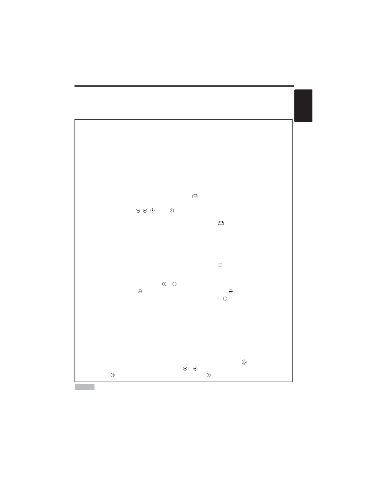
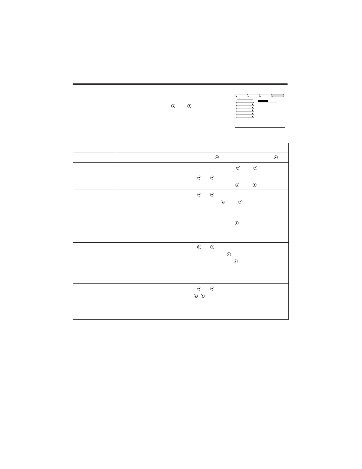
Basic Operation
The basic operations shown in Table 3 is performed from the supplied remote controller or the
projector control panel. Items indicated by (*) may be used from the control panel.
Table 3 . Basic Operation
Item Description
INPUT
SELECT
Select Input Signal (*) : Press the INPUT button.
RGB→ VIDEO → S-VIDEO → COMPONENT (→ RGB)
Select RGB Input : Press the RGB button.
VIDEO/S-VIDEO/COMPONENT → RGB
Select Video Input : Press the VIDEO button.
RGB → VIDEO/S-VIDEO/COMPONENT
VIDEO → S-VIDEO → COMPONENT (→ VIDEO)
• The selected signal name is displayed for approximately 3 seconds when the input
signal is changed.
POSITION
Set/Clear Position Adjustment Mode :
Press the POSITION button.
The [ ] icon is displayed in the POSITION mode.
Image Position Adjustment:
Press the , , and buttons in the POSITION mode.
• Valid only in the MAGNIFY mode with a video signal is input.
• After approximately 10 seconds of inactivity the [ ] icon is extinguished and the
POSITION mode is cleared automatically.
RESET (*)
Initialize Each Item : Select an item and press the RESET button.
Initialize Position Adjustment : Press the RESET button and the
POSITION mode. This function is valid only when RGB signal is input.
• Valid except for the VOLUME, LANGUAGE, H PHASE and WIHSPER.
MAGNIFY
Set MAGNIFY Mode : Press the MAGNIFY button.
Move Magnified Area : Run the POSITION in the MAGNIFY mode.
Adjust Magnification :
Press the MAGNIFY / button in MAGNIFY mode.
MAGNIFY magnifies the image ↔ MAGNIFY reduces the image
Clear MAGNIFY Mode : Press the MAGNIFY button.
• The MAGNIFY mode is cleared by running or setting the AUTO, ASPECT, INPUT
SELECT or VIDEO, or by changing the input signal.
OFF
FREEZE
Set/Clear FREEZE Mode : Press the FREEZE button. The [II] icon is
displayed, and the image frozen, in the FREEZE mode.
• The FREEZE mode is cleared by running or setting POSITION, VOLUME, MUTE,
Automatic Adjustment, BLANK ON/OFF, or MENU ON/OFF, or by changing the
input signal.
• Do not forget to clear frozen static images.
KEYSTONE
(
*)
Set/Clear KEYSTONE Mode : Press the KEYSTONE button.
Adjust Keystone : Press the / button in the KEYSTONE mode.
reduces the bottom size of image ↔ reduces the top size of image
• Use the remote controller at a distance of approximately 3m from the sensor on the front
of the projector, and within a range of 30° left-right. Strong light and obstacles will interfere with
operation of the remote controller.
NOTE
(It continue the next page.)
Page 11
ENGLISH-10
Item Description
VOLUME
Volume Adjustment : Press the VOLUME / button.
reduces the volume
↔ increases the volume
MUTE
Set/Clear Mute Mode : Press the MUTE button.
No sound is heard in the MUTE mode.
AUTO
Automatic Adjustment at RGB Input : Press the AUTO button.
Horizontal position(H.POSIT), vertical position (V.POSIT),clock phase
(H.PHASE), and horizontal size(H.SIZE) are automatically adjusted. Use
with the window at maximum size in the application display.
Automatic Adjustment at Video Input : Press the AUTO button.
A signal type appropriate for the input signal is selected automatically. Valid
only when AUTO is set for VIDEO on the menu.
• This operation requires approximately ten seconds. It may not function correctly
with some input signals.
BLANK
ON/OFF
Set/Clear Blank Mode: Press the BLANK button. No image is displayed in
the Blank mode. The screen color is as set in BLANK on the Image menu.
MENU
ON/OFF (
*)
Menu Display Start/Stop: Press the MENU button.
• The menu display is terminated automatically after approximately ten seconds of
inactivity.
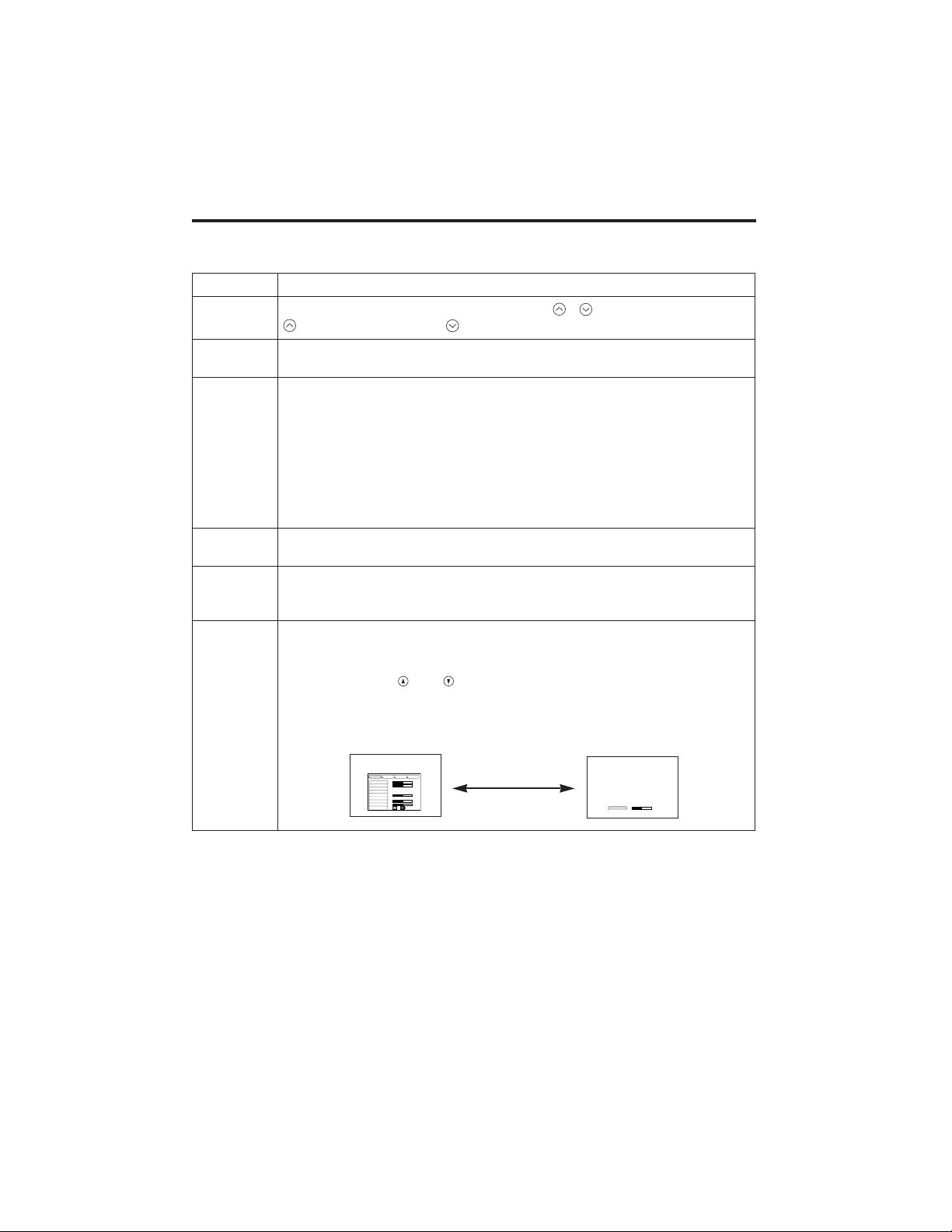
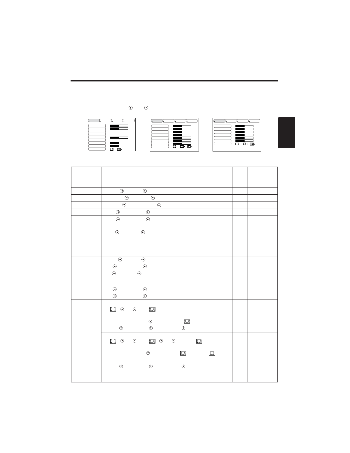
MENU
SELECT
Select Menu Type: Press the MENU SELECT button.
Allows the user to select the normal menu or the single menu. Only the
selected item is displayed on the single menu, and other items are
displayed with the and buttons as with the normal menu.
• Valid only when the Setup menu is used. Push the MENU SELECT button after
selecting items such as "BRIGHTNESS".
Normal menu Single menu
OOPPEERRAATTIIOONNSS((ccoonnttiinnuueedd)
)
Items indicated by (*) may be used from the control panel.
Table 3. Basic Operation (continued)
CONTRAST
-2
BRIGHT
CONTRAST
V POSIT
H POSIT
H PHASE
H SIZE
COLOR BAL R
COLOR BAL B
ASPECT
0
-2
+1
0
0
100
100
800
SETUP INPUT OPT.IMAGE
(MENU SELECT)
Page 12

ENGLISH-11
ENGLISH
OOPPEERRAATTIIOONNSS((ccoonnttiinnuueedd)
)
Setup Menu
The following adjustments and settings are possible when SETUP is selected at the top of the menu. Part of the
Setup menu differs between RGB input and video input. Select an item with the and buttons, and start
operation. Use the Single menu to reduce menu size (see Table 3, MENU SELECT).
VIDEO/S-VIDEO
COMPONENT
RGB
BRIGHT
CONTRAST
V POSIT
H POSIT
H PHASE
H SIZE
COLOR BAL R
COLOR BAL B
ASPECT
0
-2
+1
0
0
100
100
800
SETUP INPUT OPT.IMAGE
BRIGHT
CONTRAST
SHARPNESS
COLOR
TINT
COLOR BAL R
COLOR BAL B
ASPECT
0
+1
+1
0
0
0
0
SETUP INPUT OPT.IMAGE
Table 4. Setup Menu
Item Description
RGB
VIDEO
S-VIDEO
COMPONENT
480i
575i
480P
720P
1080i
BRIGHT
Dark ↔ Light
✔ ✔ ✔ ✔
CONTRAST
Weak ↔ Strong
✔ ✔ ✔ ✔
V POSIT
Down ↔ Up
✔
- - -
H POSIT
Left ↔ Right
✔
- - -
H PHASE
Left ↔ Right
• Adjust to eliminate flicker.
✔
-
✔ ✔
H SIZE
Small ↔ Large
• The image may not be displayed correctly if the horizontal
size is excessive. In such cases, press the RESET button, and
initialize the horizontal size.
✔
- - -
SHARPNESS
Soft ↔ Clear
-
✔
- -
COLOR
Light ↔ Dark
-
✔ ✔ ✔
TINT
Red ↔ Green
• Valid only when NTSC or NTSC 4.43 signal is received.
-
✔
- -
COLOR BAL R
Light ↔ Dark
✔ ✔ ✔ ✔
COLOR BAL B
Light ↔ Dark
✔ ✔ ✔ ✔
ASPECT
Select Image Aspect Ratio :
4:3[ ]
↔ 16:9 [ ]
Select Position of Image:
Press the button while 16:9
[]
is selected.
Center
→ Down → Up ( → Center )
✔
- -
✔
Select Image Aspect Ratio:
4:3[ ] ↔ 16:9[ ] ↔ 4:3 small[ ]
Select Position of Image :
Press the button while 16:9[ ] / 4:3
small[ ] is selected.
Center
→ Down → Up ( → Center )
• 4:3 small may not be displayed correctly with some input
signals.
-
✔ ✔
-
SETUP INPUT OPT.IMAGE
BRIGHT
CONTRAST
COLOR
H PHASE
COLOR BAL R
COLOR BAL B
ASPECT
0
+1
+1
0
0
0
Page 13
ENGLISH-12
OOPPEERRAATTIIOONNSS((ccoonnttiinnuueedd)
)
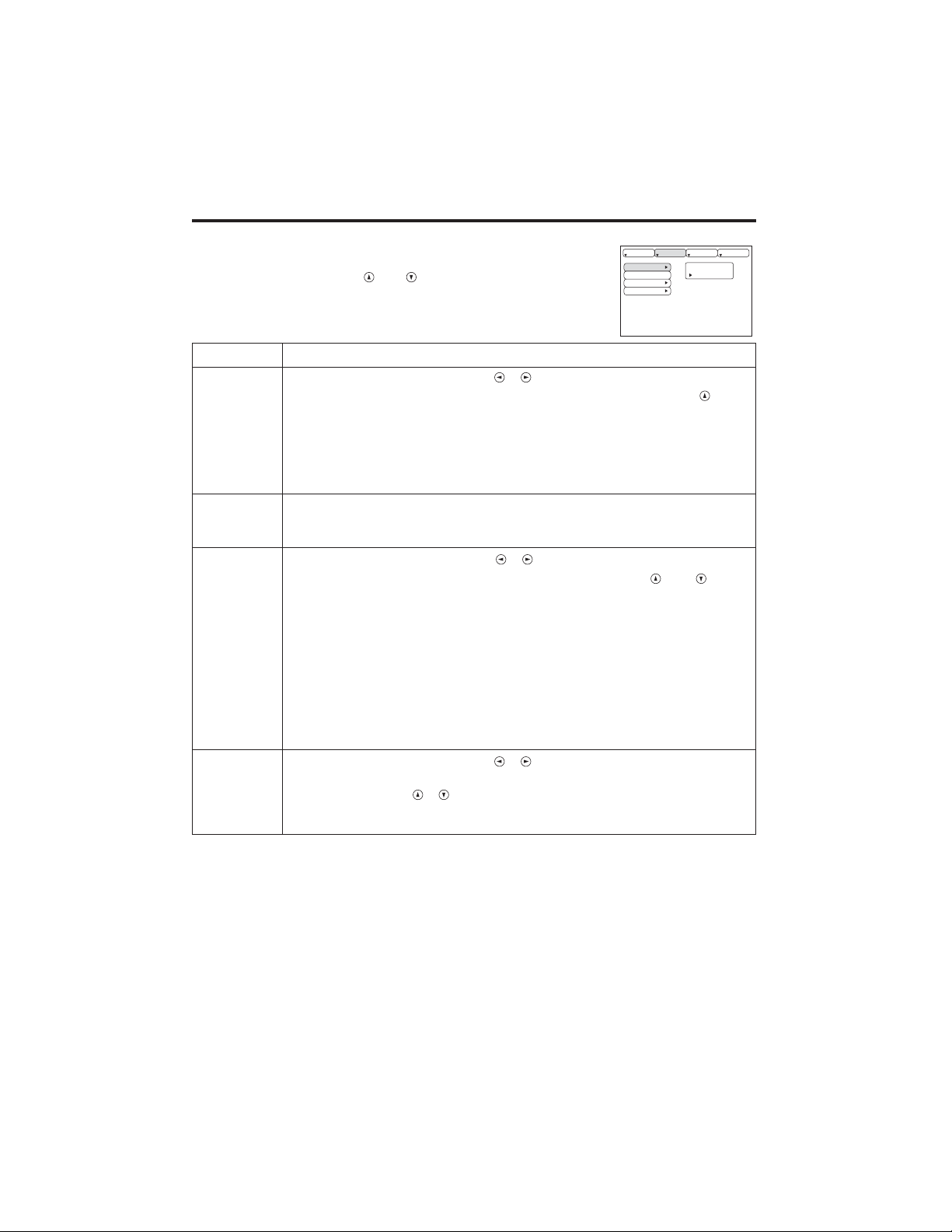
Input Menu
The following functions are available when INPUT is selected on the
menu. Select an item with the and buttons, and start operation.
Table 5. Input Menu
SETUP INPUT OPT.
Item Description
AUTO
Operation Start/Stop: Press the / button.
Automatic Adjustment at RGB Input: Select the EXECUTE with the
button.
Horizontal position (H.POSIT), vertical position (V.POSIT), clock
phase (H.PHASE), and horizontal size (H.SIZE) are automatically adjusted.
Use with the window at maximum size in the application display.
•
This operation requires approximately 10 seconds. It may not function correctly with
some input signals. Pressing the AUTO button in this case may correct this problem.
• This function is the same as for the AUTO function in Basic operation.
RGB
Displays RGB Input Frequency:
Displays the horizontal and vertical sync signal frequencies for RGB input.
• Valid only at RGB input.
VIDEO
Operation Start/Stop: Press the / button.
Select Video Signal Type: Select the signal type with the and
buttons. Select NTSC, PAL, SECAM, NTSC4.43, M-PAL, or N-PAL as
appropriate for the input signal. The selection of AUTO enables and
executes the function AUTO (Automatic Adjustment at Video Input), except
for the N-PAL input.
• Use this function when the image becomes unstable (eg. the image becomes
irregular, or lacks color) at VIDEO/S-VIDEO input.
• Automatic Adjustment requires approximately ten seconds. It may not function
correctly with some input signals. Pressing the AUTO button in this case may correct
this problem except for the N-PAL input.
• For the COMPONENT VIDEO input, this function is not effective and the signal
type is distinguished automatically.
HDTV
Operation Start/Stop: Press the / button.
Select HDTV Mode: Select the 1080i mode or 1035i mode suitable for the
input signal with the / button.
• When the selected HDTV mode is incompatible with the input signal, the image may
be incorrect (eg. the display position or color is incorrect).
AUTO
RGB
VIDEO
HDTV
IMAGE
EXECUTE
CANCEL
Page 14

ENGLISH-13
ENGLISH
OOPPEERRAATTIIOONNSS((ccoonnttiinnuueedd)
)
Image Menu
The following adjustments and settings are available when IMAGE is
selected on the menu. Select an item with the and buttons, and
start operation.
Table 6. Image Menu
SETUP INPUT OPT.IMAGE
Item Description
BLANK
Select Blank Screen Color: Select color with the and buttons.
•The image is cleared and the entire screen is displayed in the selected color, when
BLANK mode is set with BLANK ON, or when there is no signal for 5 minutes.
MIRROR
Operation Start/Stop: Press the / button.
Select Mirror Status: Select mirror status with and buttons.
START UP
Operation Start/Stop: Press the / button.
Setup Initial Screen Display: Select TURN ON with the button.
Clear Initial Screen Display: Select TURN OFF with the button.
• Note that if TURN OFF is selected the blank screen is displayed in blue when there
is no signal.
GAMMA
Operation Start/Stop: Press the / button.
Select Gamma Mode : Select the gamma mode with the / button.
COLOR
TEMP
Operation Start/Stop: Press the / button.
Select Color Temperature:
Select the color temperature mode with the / button.
BLANK
MIRROR
START UP
GAMMA
COLOR TEMP
Page 15
ENGLISH-14
OOPPEERRAATTIIOONNSS((ccoonnttiinnuueedd)
)
Options Menu
The following adjustments and settings are available when OPT. is
selected on the menu. Select an item with the and buttons, and
start operation.
.
Table 7. Options Menu
VOLUME
MENU COLOR
LANGUAGE
AUTO OFF
SYNC ON G
WHISPER
16
SETUP INPUT OPT.IMAGE
Item Description
VOLUME
Volume Adjustment: Reduce VOLUME ↔ Increase VOLUME
MENU COLOR
Select Menu Background Color: Select with the and buttons.
LANGUAGE
Operation Start/Stop: Press the or button.
Select Menu Display Language: Select with the and buttons.
AUTO OFF
Operation Start/Stop: Press the or button.
Set AUTO OFF: Set 1~99 minutes with the and buttons. The
system automatically enters the standby mode when a signal is not
received for the set time.
Clear AUTO OFF: Select STOP (0 min.) with the button. When
STOP is selected the system does not enter the standby mode even if
no signal is received.
SYNC ON G
Operation Start/Stop: Press the or button.
SYNC ON G Valid: Select TURN ON with the button.
SYNC ON G Invalid: Select TURN OFF with the button.
• May not be displayed correctly with some input signals when SYNC ON G is
valid. In such cases, remove the signal connector so that no signal is received,
set SYNC ON G to invalid, and reconnect the signal.
WHISPER
Operation Start/Stop: Press the or button.
Set/Clear Wisper Mode: Press
/ button.
When the WHISPER is
selected, the WHISPER mode is active. In the WHISPER mode,
acoustic noise level from the unit is reduced, brightness level on screen
is a little lower.
Page 16

ENGLISH-15
ENGLISH
OOPPEERRAATTIIOONNSS((ccoonnttiinnuueedd)
)
No Signal Menu
The same adjustments and settings are available with the Image and
Options menus when the MENU button is pressed during display of the
“NO INPUT IS DETECTED ON ***” or “SYNC IS OUT OF RANGE
ON ***” message while no signal is received.
Table 8. No Signal Menu
VOLUME
BLANK
MIRROR
START UP
MENU COLOR
LANGUAGE
AUTO OFF
SYNC ON G
WHISPER
16
Item Description
VOLUME
Volume Adjustment: Reduce VOLUME ↔ Increase VOLUME
• When this function is used, audio input is automatically switched to video. The
audio input can be switched by moving the DISK PAD left and right during the
display of the volume adjustment bar. The volume adjustment bar is displayed by
pressing VOLUME or VOLUME button.
BLANK
Select Blank Screen Color: Select the color with the and buttons.
•The image is cleared and the entire screen is displayed in the selected color,
when BLANK mode is set with BLANK ON, or when there is no signal for 5
minutes.
MIRROR
Operation Start/Stop: Press the / button.
Select Mirror Status: Select the mirror status with the and buttons.
START UP
Operation Start/Stop: Press the / button.
Setup Initial Screen Display: Select the TURN ON with the button.
Clear Initial Screen Display: Select the TURN OFF with the button.
• Note that if TURN OFF is selected the blank screen is displayed in blue when there is no signal.
MENU COLOR
Select Menu Background Color: Select the color with the and buttons.
LANGUAGE
Operation Start/Stop: Press the / button.
Select Menu Display Language: Select the language with the and
buttons.
AUTO OFF
Operation start/stop: Press the / button.
Set AUTO OFF: Set 1~99 minutes with the and buttons. The
system automatically enters the standby mode when a signal is not
received for the set time.
Clear AUTO OFF: Select the STOP (0 min.) with the button. When
the STOP is selected the system does not enter the standby mode even
if no signal is received.
SYNC ON G
Operation Start/Stop: Press the / button.
SYNC ON G Valid: Select the TURN ON with the button.
SYNC ON G Invalid: Select the TURN OFF with the button.
• May not be displayed correctly with some input signals when the SYNC ON G is
valid. In such cases, remove the signal connector so that no signal is received,
set the SYNC ON G to invalid, and reconnect the signal.
WHISPER
Operation Start/Stop: Press the / button.
Set/Clear Wisper Mode: Press / button. When the WHISPER is
selected, the WHISPER mode is active. In the WHISPER mode,
acoustic noise level from the unit is reduced, brightness level on screen
is a little lower.
Page 17
ENGLISH-16
MAINTENANCE
MAINTENANCE
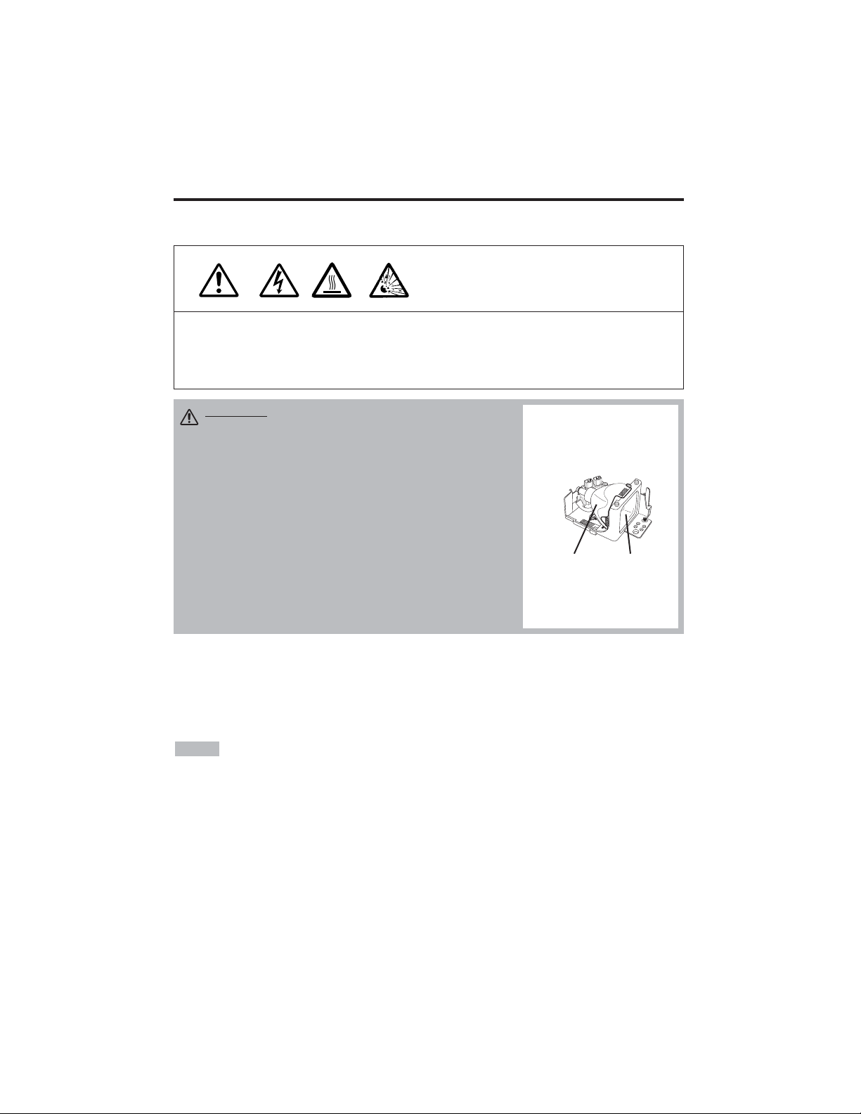
Lamp
HIGH VOLTAGE
HIGH TEMPERATURE
HIGH PRESSURE
Contact your dealer before replacing the lamp.
For the optional lamp, see the item “Optional Parts” of the Table 12.
Before replacing the lamp, switch power OFF, remove the power cord from the power outlet, and
wait approximately 45 minutes until the lamp has cooled. The lamp may explode if handled at high
temperatures.
Lamp Life
Projector lamps have a finite life. The image will become darker, and hues will become weaker,
after a lamp has been used for a long period of time.
Replace the lamp if the LAMP indicator is red, or the CHANGE THE LAMP message appears
when the projector is switched ON. See Table 9 of P.19 and Table 10 of P.20.
• The LAMP indicator is also red when the lamp unit reaches high temperature. Before
replacing the lamp, switch power OFF, wait approximately 20 minutes, and switch power ON again.
If the LAMP indicator is still red, replace the lamp.
NOTE
WARNING • For disposal of used lamp, treat
according to the instruction of community
authorities.
• Since the lamp is made of glass, do not apply shock
to it and do not scratch it.
• Also, do not use old lamp. This could also cause
explosion of the lamp.
• If it is probable that the lamp has exploded (explosive
sound is heard), disconnect the power plug from the
power outlet and ask your dealer to replace lamp. The
lamp is covered by front glass, but in rare cases, the
reflector and the inside of the projector may be
damaged by scattered broken pieces of glass, and
broken pieces could cause injury when being handled.
• Do not use the projector with the lamp cover removed.
Lamp
Front
glass
Reflector
Page 18
ENGLISH-17
ENGLISH
MMAAIINNTTEENNAANNCCEE((ccoonnttiinnuueedd)
)
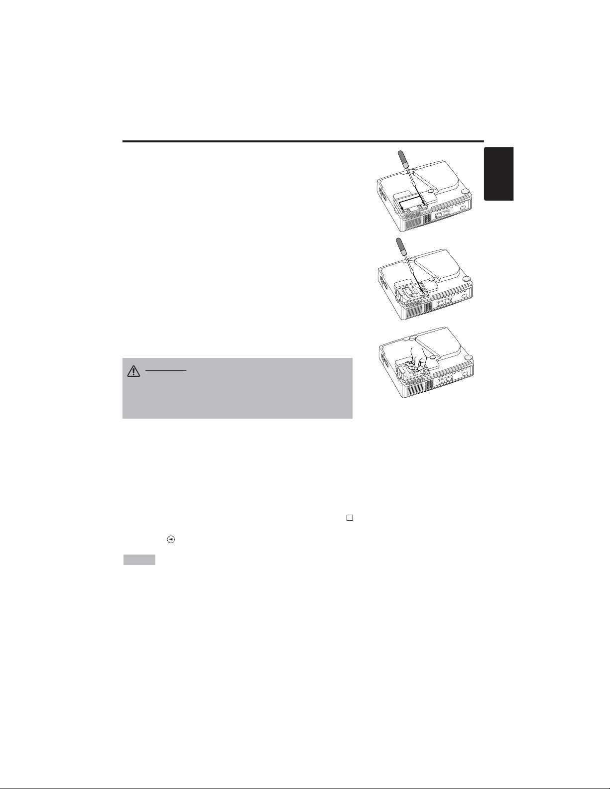
Replacing the Lamp
1. Switch the projector OFF, remove the power cord from the
power outlet, and wait at least 45 minutes for the unit to cool.
2. Prepare a new lamp.
3. Check that the projector has cooled sufficiently, and gently
turn it upside down.
4. Loosen the two screws as shown in the diagram, and remove
the lamp cover.
5. Loosen the one screw, and gently remove the lamp while
holding the grips. Touching the inside of the lamp case may
result in uneven coloring.
6. Install the new lamp and tighten the one screw firmly. Also
steadily push the opposite side of the screwed lamp into the
unit.
7. Replace the lamp cover in position and tighten the two
screws firmly.
8. Gently turn the projector right-side up.
Resetting the Lamp Timer
Reset the lamp timer after replacing the lamp. When the message of “CHANGE THE LAMP …
THE POWER WILL TURN OFF AFTER 0 hr.” is displayed, complete the following operation
within 10 minutes. The power will be turned off automatically in over 10 minutes.
1. Switch power ON, and press the RESET button, for approximately three seconds. The ‘LAMP
xxxx hr’ message will appear on the lamp timer on the bottom of the screen.
2. Press the MENU button on the remote control transmitter, or the RESET button on the control
panel, while the lamp timer is displayed. The ‘LAMP xxxx
→ 0 ■ CANCEL’ message will
then appear.
3. Press the and select 0, and wait until the timer display is cleared.
• Do not reset the lamp timer without replacing the lamp. Reset the lamp timer always
when replacing the lamp. The message functions will not operate properly if the lamp timer is not
reset correctly.
NOTE
CAUTION • Ensure that screws are tightened
properly. Screws not tightened fully may result
in injury or accidents.
• Do not use the projector with the lamp cover
removed.
Page 19

ENGLISH-18
MMAAIINNTTEENNAANNCCEE((ccoonnttiinnuueedd)
)
Air Filter Maintenance
The air filter should be cleaned as described below at intervals of approximately 100 hours.
1. Switch the projector power supply OFF, and remove the power cord from the power outlet.
2. Clean the air filter with a vacuum cleaner.
Other Maintenance
Maintenance Inside the Equipment
For safety reasons, ensure that the equipment is cleaned and checked by the dealer once every two
years. Maintaining the equipment by yourself is dangerous.
Cleaning the Lens
Gently wipe the lens with lens cleaning paper. Do not touch the lens with your hands.
Cleaning the Cabinet and Remote control transmitter
Gently wipe with a soft cloth. If dirt and stains etc. are not easily removed, use a soft cloth
dampened with water, or water and a neutral detergent, and wipe dry with a soft, dry cloth.
CAUTION • Switch power OFF and remove the power cord from the power
outlet before beginning maintenance work. Please read the separate “SAFETY
INSTRUCTIONS” thoroughly to ensure that maintenance is performed correctly.
• Do not use detergents or chemicals other than those noted above (e.g. benzene
or thinners).
• Do not use cleaning sprays.
• Do not rub with hard materials, or tap the equipment.
CAUTION • Switch power OFF and remove the power cord from the power
outlet before beginning maintenance work. Please read the separate “SAFETY
INSTRUCTIONS” thoroughly to ensure that maintenance is performed correctly.
• Replace the air filter if contamination cannot be removed, or if it is damaged.
Contact your dealer in such case. For the optional air filter, see the item “Optional
Parts” of the Table 12.
• Do not use the equipment with the air filter removed.
• When the air filter is clogged with dust etc. the power supply is switched OFF
automatically to prevent the temperature rising inside the projector.
Page 20

ENGLISH-19
ENGLISH
TROUBLESHOOTING
TROUBLESHOOTING
OSD Message
The messages as described below may appear on the screen at power ON. Take the appropriate
measures when such messages appears.
Table 9. OSD Messages
Message Contents
CHANGE THE LAMP
AFTER REPLACING LAMP,
RESET THE LAMP TIME.
(*1)
The usage time of lamp will be reaching 2000 hr
shortly.(*2)
It is recommended to replace the lamp soon. Prepare a
new lamp as a replacement.
CHANGE THE LAMP
AFTER REPLACING LAMP,
RESET THE LAMP TIME.
THE POWER WILL TURN OFF
AFTER ** hr.
(*1)
The usage time of lamp will be reaching 2000 hr shortly.
It is recommended to replace the lamp within * *
hours.(*2)
It might be happened that the lamp is cut off before * * hr
by any chance. Power will be switched OFF
automatically in * * hours. Replace the lamp as shown in
P.17~18 “Lamp”. Always reset the lamp timer after
replacing the lamp.
CHANGE THE LAMP
AFTER REPLACING LAMP,
RESET THE LAMP TIME.
THE POWER WILL
TURN OFF
AFTER 0 hr.
The usage time of lamp is about to reach. Power will be
switched OFF in a few minutes.(*2)
Switch power OFF immediately and replace the lamp as
shown in P.17 ~18 “Lamp”. Always reset the lamp timer
after replacing the lamp.
NO INPUT IS DETECTED
ON ***
No input signal found.
Check signal input connections and signal sources.
SYNC IS OUT OF RANGE
ON ***
The horizontal or vertical frequency of the input signal is
not within the specified range.
Check the specifications of the equipment and the signal
source.
(*1) This message is cleared automatically after approximately three minutes, and
appears every time power is switched ON.
(*2) The unit has a function to turn the power off which will be active when the usage time reaches
2000 hr. However the life of lamp might be much different among lamps, so that it might be
happened that a lamp is cut off before the function is active.
NOTE
Page 21
ENGLISH-20
TTRROOUUBBLLEESSHHOOOOTTIINNGG((ccoonnttiinnuueedd)
)
Indicators Message
The POWER indicator, LAMP indicator, and TEMP indicator are lit and blank as follows. Take the
appropriate measures.
Table 10. Indicators Message
POWER
indicator
LAMP
indicator
TEMP
indicator
Contents
Lights
orange
Turns off Turns off
The Standby mode has been set.
Blinks
green
Turns off Turns off
Warming up. Please wait.
Lights
green
Turns off Turns off
ON. Normal operation possible.
Blinks
orange
Turns off Turns off
Cooling. Please wait.
Blinks red - -
Cooling. Please wait.
The error is found. Take the appropriate measures when the
POWER indicator ceases blinking
Blinks
/Lights red
Lights
red
Turns off
Lamp is not lit.
The interior of the equipment may be too hot. Switch power OFF,
wait 20 minutes until the equipment cools, and check whether the
ventilation openings are blocked, whether the air filter is dirty, or
whether the ambient temperature exceeds 35 °C. And switch
power ON again. Replace the lamp if the same problem occurs.
Blinks
/Lights red
Blinks
red
Turns off
Lamp or lamp cover is not found, or hasn’t been fitted in correctly.
Switch power OFF, and wait for 45 minutes until the equipment
cools. Check fitting of the lamp and lamp cover, and switch power
ON again. Contact your dealer if the same problem occurs again.
Blinks
/Lights red
Turns off
Blinks
red
The cooling fan is not operating.
Switch power OFF, and wait for 20 minutes until the equipment
cools. Check for foreign matters in the fan, and switch power ON
again. Contact your dealer if the same problem occurs again.
Blinks
/Lights red
Turns off Lights red
The interior of the equipment is too hot. *2)
Switch power OFF, and wait for 20 minutes until the equipment
cools. Check whether the ventilation openings are blocked,
whether the air filter is dirty, or whether the ambient temperature
exceeds 35 °C. Then switch power ON again. Contact your dealer if
the same problem occurs again.
Lights
green
Blinks
red
Blinks
red
The interior of the equipment is too cool.
Check whether the ambient temperature is below 0°C. Contact your
dealer if the same problem occurs when the ambient temperature is
0~35°C.
*2) When the internal temperature becomes excessive power is switched OFF
automatically for safety reasons, and the indicator is extinguished. Set the power switch to [
O
] and
wait for 20 minutes until the equipment has cooled sufficiently.
NOTE
Page 22

ENGLISH-21
ENGLISH
TTRROOUUBBLLEESSHHOOOOTTIINNGG((ccoonnttiinnuueedd)
)
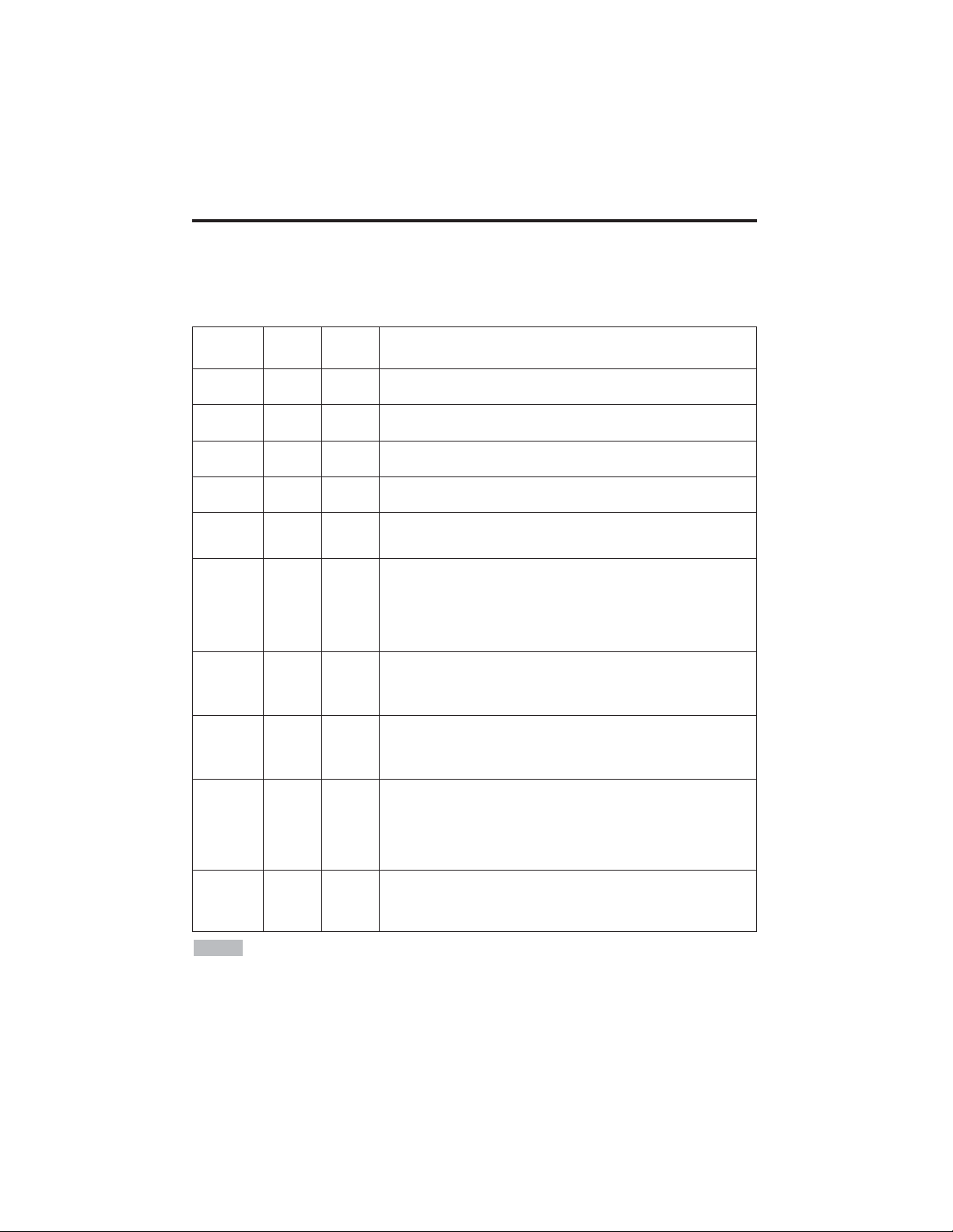
Symptom
Before requesting repair, check in accordance with the following chart. If the situation cannot be
corrected, then contact your dealer.
Table 11. Symptom
Symptom Possible cause Remedy Page
The power is not
turned on.
The main power switch is not
turned on.
Turn on the main power switch.
7,8
The power cord is
disconnected.
Plug the power cord into an AC
power outlet.
No video or audio.
The input is not correctly set.
Use the projector or remote control
transmitter to set.
9
No signal input. Connect correctly.
6,7
Video is present but
no audio.
The projector is not correctly
connected.
Connect correctly.
6,7
The volume is set to minimum.
Press VOLUME on the remote
control or display the menu screen
and adjust the volume.
10,14
Mute is turned on.
Press the MUTE button.
10
Audio is present but
no video.
The projector is not correctly
connected.
Connect correctly.
6,7
The brightness is set to
minimum.
Select BRIGHT with the MENU
button and the press the button.
11
The slide lens door is still
closed.
Open the slide lens door.
8
Colors are pale and
color matching is
poor.
Color density and color
matching are not correctly
adjusted.
Adjust the video.
11
Images are dark.
Brightness and contrast are not
correctly adjusted.
Adjust the video.
11
The lamp is nearing the end of
its service life.
Replace with a new lamp.
16,17
Images are blurred.
Focus or H PHASE is out of
adjustment.
Adjust the focus or H PHASE.
8,11
Page 23
ENGLISH-22
SPECIFICATIONS
SPECIFICATIONS
Table 12. Specifications
• This specifications are subject to change without notice.
NOTE
Item Specification
Product name Liquid crystal projector
Liquid
crystal
panel
Panel size 1.8 cm (0.7 type)
Drive system TFT active matrix
Pixels
CP-S225W : 480,000 pixels (800 horizontal x 600 vertical)
CP-X275W : 786,432 pixels (1024 horizontal x 768 vertical)
Lens Zoom lens F=2.0 ~ 2.3 f=18 ~ 21 mm
Lamp 150 W UHB
Speaker 1.0 W
Power supply AC100 ~ 120V, 2.7A / AC220 ~ 240V, 1.3A
Power consumption 240 W
Temperature range 0 ~ 35°C (Operating)
Size 289 (W) x 84 (H) x 215 (D) mm
Weight (mass)
CP-S225W : 2.4 kg
CP-X275W : 2.5 kg
RGB
signal
input
RGB IN
Video: Analog 0.7Vp-p, 75Ω terminator (positive)
H/V. sync.: TTL level (positive/negative)
Composite sync.: TTL level
D-sub 15-pin shrink jack
AUDIO IN
200mVrms, 47 kΩ (max. 3.0Vp-p)
Stereo mini jack
Video
signal
input
VIDEO
1.0Vp-p, 75Ω terminator
RCA jack
S-VIDEO
Brightness signal: 1.0Vp-p, 75Ω terminator
Color signal: 0.286Vp-p (NTSC, burst signal), 75Ω terminator
0.3Vp-p (PAL/SECAM, burst signal), 75Ω terminator
Mini DIN 4-pin jack
COMPONENT
VIDEO
Y 1.0 Vp-p, 75 Ω Terminator (Positive)
CB/CR 0.7 Vp-p, 75 Ω Terminator (Positive)
PB/PR 0.7 Vp-p, 75 Ω Terminator (Positive)
AUDIO
L
200mVrms, 47 kΩ (max. 3.0Vp-p)
RCA jack
R
Control
functions
CONTROL D-sub 15-pin shrink plug
Optional Parts
Lamp: DT00401 (CP-S225W) / DT00461 (CP-X275W)
Air Filter: MU01461
* For others, consult your dealer.
Page 24

ENGLISH-23
ENGLISH
WARRANTY AND AFTER-SERVICE
WARRANTY AND AFTER-SERVICE
If a problem occurs with the equipment, first refer to the P.20 “TROUBLESHOOTING” section and
run through the suggested checks. If this does not resolve the problem contact your dealer or service
company. They will tell you what warranty condition is applied.
Page 25

Page 26

DEUTSCH - 1
DEUTSCH
Herzlichen Glückwunsch zum Kauf dieses Flüssigkristall-Projektors von.
INHAIT
INHAIT
•
Änderungen der in dieser Bedienungsanleitung gegebenen Informationen bleibt
jederzeit vorbehalten.
• Der Hersteller haftet nicht für möglicherweise in dieser Bedienungsanleitung
vorhandene Fehler. • Reproduktion, Übertragung oder Verwendung dieses Dokumentes bzw. seines
Inhalts ist ohne ausdrückliche schriftliche Erlaubnis nicht zulässig.
ANERKENNUNG VON WARENZEICHEN :
PS/2, VGA und XGA sind eingetragene Warenzeichen
der International Business Machines Corporation.
Apple, Mac und ADB sind eingetragene
Warenzeichen der Apple Computer, Inc. VESA und SVGA sind Warenzeichen der Video
Electronics Standard Association. Windows ist ein eingetragenes Warenzeichen der Microsoft
Corporation. Beachten Sie sorgfältig die Warenzeichen und eingetragenen Warenzeichen aller
Firmen, selbst wenn diese nicht erwähnt sind.
HINWEISE
Seite
EIGENSCHAFTEN............................2
VOR DER VERWENDUNG...............2
Inhalt der Packung..................................2
Namen der Teile.....................................3
Einlegen der Batterie..............................4
INSTALLATION ................................5
Installation von Projektor und Bildschirm
......5
Winkeleinstellung....................................5
Kabelanschluß........................................6
Netzanschluß..........................................7
Beispiel für Systemeinrichtung ...............7
Plug & Play.............................................7
BEDIENUNG .....................................8
Einschalten.............................................8
Ausschalten............................................8
Grundbtrieb.............................................9
Einstellungsmenü .................................11
Eingansmenü........................................12
Abbldmenü ...........................................13
Optionemenü........................................14
Kein-Signal-Menü.................................15
WARTUNG......................................16
Lampen.................................................16
Luftfilterwartung....................................18
Sonstige wartung..................................18
Seite
STÖRUNGSSUCHE........................19
OSD-Meldungen...................................19
Anzeigemeldung...................................20
Symptom ..............................................21
TECHNISCHE DATEN....................22
GARANTIE UND KUNDENDIENST
.....23
....................................................................
TABELLEN
Tabelle 1. Installationsbezug....................5
Tabelle 2. Kabelanschluß.........................6
Tabelle 3. Grundbtrieb..............................9
Tabelle 4. Einstellungsmenü ..................11
Tabelle 5. Eingansmenü.........................12
Tabelle 6. Abbldmenü.............................13
Tabelle 7. Optionemenü .........................14
Tabelle 8. Kein-Signal-Menü ..................15
Tabelle 9. OSD-Meldungen....................19
Tabelle 10. Anzeigemeldung..................20
Tabelle 11. Symptom..............................21
Tabelle 12. Technische Daten................22
....................................................................
Beziehen Sie sich für "TECHNICAL"
(Technisch) und "REGULATORY
NOTICE" (Ausführungshinweis) auf das
Ende dieses Bedienungsanleitung.
Flüssigkristall-Projektor
BEDIENUNGSANLEITUNG
BEDIENUNGSANLEITUNG
WARNUNG • Bitte lesen Sie die beiliegende Broschüre
“SICHERHEITSVORSCHRIFTN” und diese “BEDIENUNGSANLEITUNG”
gründlich durch, um korrekte Verwendung durch richtiges Verständnis
sicherzustellen. Bewahren Sie die Bedienungsanleitung nach dem Durchlesen
für spätere Bezugnahme an einem sicheren Ort auf.
Page 27

DEUTSCH - 2
EIGENSCHAFTEN
EIGENSCHAFTEN
Dieser Flüssigkristallprojektor dient zum Projizieren von Computergrafiken und
NTSC/PAL/SECAM-Videobildern auf eine Leinwand. Großflächige Projektion ist problemlos
möglich, und das Gerät benötigt zur Aufstellung nur wenig Platz.
Hervorragende Helligkeit
Die UHB-Lampe und die Hochleistungsoptik des Geräts sorgen zusammen für optimale
Bildhelligkeit.
Partielle Vergrößerungsfunktion
Interessante Bildteile können für nähere Betrachtung vergrößert werden.
Verzerrungskorrekturfunktion
Verzerrungsfreie Bilder sind schnell verfügbar.
Extra-Leise-Funktion
Der Geräuschpegel des Gerätes kann reduziert werden.
VOR DER VERWENDUNG
VOR DER VERWENDUNG
Inhalt der Packung
Stellen Sie sicher, daß alle folgenden Teile in der Packung enthalten sind. Wenden Sie sich bitte an
Ihren Händler, wenn Teile fehlen sollten.
• Bewahren Sie das Originalverpackungsmaterial für späteren Transport auf.
HINWEISE
Projektor
Bedienungsanleitung
(diese Anleitung)
Sicherheitsvorschriften
Netzkabel
(US-Typ)
Netzkabel
(UK-Typ)
Netzkabel
(europäischer Typ)
RGB-Kabel
Komponenten-
Videokabel
(mit grünem Streifen)
Fernbedienung mit
Batterie
Tragetasche
STANDBY/ON
KEYSTONE
MAGNIFY
VIDEO
RGB
MENU
SELECT
MENU RESET
POSITION
FREEZE
VOLUME
MUTE
OFF
AUTO
BLANK
Page 28
DEUTSCH - 3
DEUTSCH
VVOORRDDEERRVVEERRWWEENNDDUUNNGG((ffoorrttsseettzzuunngg)
)
Namen der Teile
Netzschalter
Netzanschluß
(für Netzkabel)
Ventilationsöffnungen
(Einlaß)
Zoom-Knopf
Fokusring
Fernbedienungssensor
Objektiv
Gleitende
Objektivabdeckung
Fußeinstellung
Ansicht von links vorn
Taste RESET
Taste KEYSTONE
Taste INPUT
Taste STANDBY/ON
Fußeinstellknopf
Luftfilter und Einlaß
(für den Kühlventilator)
Lautsprecher
Hintere Fußeinstellung
Anzeige LAMP
Anzeige TEMP
Anzeige POWER
Anzeige MENU
Ventilationsöffnungen
(Auslaß)
Ansicht von rechts hinten
Anschlüsse
(siehe unten)
Bedienungsfeld (Vgl.Seite 8 “BEDIENUNG”.)
Fernbedienungssensor
COMPONENT
Anschluß Y
Anschluß C
B/PB
Anschluß CR/PR
Anschluß S-VIDEO
Anschluß RGB
Anschluß CONTROL
Anschluß AUDIO
AUDIO
Anschluß R
Anschluß L
Anschluß VIDEO
Anschlüsse
Page 29

DEUTSCH - 4
VVOORRDDEERRVVEERRWWEENNDDUUNNGG((ffoorrttsseettzzuunngg)
)
Namen der Teile (fortsetzung)
Einlegen der Batterien
Erstes Einlegen:
In der Originalverpackung ist die Batterie im Batteriehalter der
Fernbedienung mit einem Schutzfilm (den transparenten Film,
der teilweise im Batteriefach ist) installiert. Ziehen Sie den
Schutzfilm heraus, um die Batterie zu laden.
Auswechseln:
1. Drehen Sie die Fernbedienung um.
2. Drücken Sie die Nut und ziehen Sie den Batteriehalter wie
rechts gezeigt heraus.
3. Entfernen Sie die verbrauchte Batterie.
4. Legen Sie die neue Batterie mit der Seite “+” nach oben ein.
5. Schieben Sie den Batteriehalter ein, bis er einrastet.
Herausziehen
Seite “+”
Batteriehalter
Fernbedienugsteil
(Vgl. Seite 8 “BEDIENUNG”.)
STANDBY/ON
Taste STANDY/ON
Taste KEYSTONE
Taste
Taste
Taste
Taste
Taste MENU
Taste MAGNIFY
Taste MAGNIFY
Taste MAGNIFY
Taste AUTO
Batteriehalter
OFF
Taste VIDEO
Taste RGB
Taste MENU SELECT
Taste POSITION
Taste RESET
Taste VOLUME
Taste VOLUME
Taste FREEZE
Taste MUTE
Taste BLANK
Wechseln Sie die Batterien aus, wenn die Wirksamkeit der Fernbedienung nachlässt.
HINWEISE
VORSICHT •Falsche Behandlung der Batterie kann einen Brand oder Verletzungen zur
Folge haben. Bei unsachgemäßer Behandlung kann die Batterie explodieren. Die
Batterie vorsichtig entsprechend den Anweisungen in den mitgelieferten
"SICHERHEITSVORSCHRIFTN" und in dieser Anleitung handhaben.
• Verwenden Sie nur eine 3-V-Mikrolithiumbatterie vom Typ Nr. CR2025.
• Achten Sie beim Einlegen der Batterien darauf, dass Plus- und Minuspol gemäß der
Angabe in der Fernbedienung korrekt ausgerichtet sind.
• Die Batterie vorschriftsmäßig entsprechend den lokalen Vorschriften entsorgen.
• Die Batterie außerhalb der Reichweite von Kindern und Haustieren halten.
• Wenn die Fernbedienung längere Zeit nicht benutzt wird, nehmen Sie die Batterien heraus.
KEYSTONE
VIDEO
MENU
SELECT
RGB
MENU RESET
MAGNIFY
OFF
AUTO
POSITION
FREEZE
VOLUME
MUTE
BLANK
Page 30

DEUTSCH - 5
DEUTSCH
INSTALLATION
INSTALLATION
Installation von Projektor und Bildschirm
Beziehen Sie sich für die Bestimmung der Bildschirmgröße und des Projektionsabstands auf die
folgende Zeichnung und Tabelle.
Die Projektionsabstände, die in der Tabelle folgend gezeigt
werden, sind für Größengleich (CP-S225W:800 x 600 Punkte
/ CP-X275W:1024 x 768 Punkte)
a: Entfernung des Projektors zur Leinwand. (±10%)
b: Entfernung von der Objektivmitte bis zum Boden der Leinwand.
(±10%)
Tabelle 1. Installationsbezug
Bildschirmgröße
[m]
a [m]
b
[cm]
Minimal Maximal
1,0 0,9 1,2 8,7
1,5 1,5 1,8 13,1
2,0 1,9 2,4 17,4
2,5 2,4 2,9 21,8
3,0 2,9 3,5 26,1
3,8 3,7 4,4 32,7
5,0 4,9 5,9 43,5
Objektivmitte
Leinwand
VORSICHT • Installieren Sie den Projektor in einer angemessenen Umgebung
entsprechend den Anweisungen in der beiliegenden Broschüre
“SICHERHEITSVORSCHRIFTN” und in dieser Bedienungsanleitung.
• Den Flüssigkristallprojektor grundlegend waagerecht aufstellen. Wenn Sie den
Flüssigkristallprojektor mit dem Objektiv nach oben nach unten, oder auf die Seite gestellt
verwenden, kann dies zu Wärmestau im Projektor führen und Beschädigung verursachen.
Achten Sie besonders darauf, die Ventilationsöffnungen bei der Installation nicht zu
blockieren.
• Installieren Sie den LCD-Projektor nicht in einer rauchgefüllten Umgebung. Rauchpartikel
können sich auf wichtigen Teilen (z.B. LCD-Fenster, Linsengruppe usw.) ablagern.
Winkeleinstellung
Verwenden Sie die Fußeinsteller an
der Unterseite des Projektors zum
Einstellen des Projektionswinkels.
Einstellung ist von 0° bis etwa 10°
möglich.
1. Heben Sie die Vorderseite des
Projektors an. Drücken Sie auf den
Fußeinstellknopf und stellen Sie
den Projektionswinkel ein.
2. Lassen Sie den Knopf los, um den
eingestellten Winkel zu fixieren.
3. Drehen Sie den hinteren
Einstellfuß, um seitliche Neigung
zu beseitigen.
VORSICHT • Lassen Sie den Fußeinstellknopf nur los, während der Projektor
gehalten wird, da der Projektor sonst umkippen oder die Finger einklemmen
und Körperverletzungen verursachen kann.
AUFSICHT
SEITENANSICHT
a
b
Fußeinsteller
Drücken Sie den
Fußeinstellknopf.
Hintere
Fußeinstellung
Page 31

DEUTSCH - 6
IINNSSTTAALLLLAATTIIOONN((ffoorrttsseettzzuunngg)
)
• Lesen Sie vor dem Anschluss die Bedienungsanleitungen der zu verbindenden Geräte durch,
um sicherzugehen, dass der Projektor mit dem Gerät kompatibel ist.
• Ziehen Sie zur Sicherheit die Schrauben der Stecker an.
• Bei einigen Modellen wird der gesondert erhältliche Mac-Adapter benötigt.
• Zur Wahl des digitalen RGB-Eingangs sind eventuell Einstellungen am Computer erforderlich. Einzelheiten
entnehmen Sie bitte den Computer-Handbüchern.
• Manche Computer können mehrere Bildschirmmodi haben. Nicht alle dieser Modi können mit diesem
Projektor verwendet werden.
• Angaben zur Stiftbelegung der Anschlüsse entnehmen Sie bitte dem Abschnitt "TECHINICAL".
• Angaben zu den Kommunikationsdaten entnehmen Sie bitte der Gebrauchsanweisung des gesonderten RS-
232C-Kabels.
• Wenden Sie sich bezüglich anderer Teile an Ihren Händler.
HINWEISE
Funktion Buchse Kabel
Analoger RGB-Eingang RGB
Mitgeliefertes RGB-Kabel oder gesondertes
RGB-Kabel mit 15-polig.em D-SubKompaktstecker und Zollgewindeschrauben
RS-232C-Anschluss CONTROL Gesondertes RS-232C-Kabel
Audio-Eingang
(vom Computer)
AUDIO
Gesondertes Audiokabel mit Stereo-MiniStecker
Komponenten-VideoEingang
COMPONENT VIDEO Y
Gesondertes Komponenten-Videokabel
COMPONENT VIDEO CB/PB
COMPONENT VIDEO PR/CB
S-Video-Eingang S-VIDEO
Gesondertes S-Video-Kabel mit 4-poligem
Mini-DIN-Stecker
Video-Eingang VIDEO
Gesondertes Video/Audio-Kabel mit CinchStecker
Audio-Eingang
(vom Videogerät)
AUDIO L
AUDIO R
Kabelanschluß
Sprechen Sie die Tabelle unten für das Anschließen jedes Terminals des Projektors an jede Einheit an.
Tabelle 2. Kabelanschluß
VORSICHT • Falscher Anschluß kann einn Brand oder e elektrischen Schlag
verrursachen. Bitte lessen Sie diese Bedienungsanleitung und die separaten
“SICHERHEITSVORSCHRIFTEN”.
• Schalten Sie vor dem Anschluss alle anzuschließenden Geräte außer dem USB-Kabel aus.
• Die Kabel müssen möglicherweise mit dem Kern auf der Projektorseite angebracht
verwendet werden. Verwenden Sie die mit dem Projektor mitgelieferten Kabel bzw. die
festgelegten Kabel.
Page 32

DEUTSCH - 7
DEUTSCH
IINNSSTTAALLLLAATTIIOONN((ffoorrttsseettzzuunngg)
)
Beispid für Systemeinrichtung
Netzanschluß
Verwenden Sie entsprechend der zu verwendenden Steckdose das angemessene mitgelieferte Netzkabel.
Schließen Sie den Netzanschluß des Projektors mit dem Netzkabel sicher an eine Steckdose an.
Computer
(Notebook)
• Sorgen Sie beim Anschluß an einen Notebook-Computer dafür, daß der externe RGBBildausgang wirksam ist (stellen Sie auf CRT-Anzeige oder auf gleichzeitige LCD- und CRT-Anzeige). Bitte
beziehen Sie sich für weitere Informationen auf die Bedienungsanleitung für das Notebook.
Plug & Play
Dieser Projektor ist mit VESA DDC 1/2B kompatibel. Plug & Play ist durch Anschluß des
Projektors an einen Computer, der mit VESA DC (Display-Datenkanal) kompatibel ist, möglich.
Bitte benutzen Sie diese Funktion, indem Sie das mitgelieferte RGB-Kabel an die Buchse RGB. Plug and
Play funktioniert bei anderem Anschluss eventuell nicht.
• Plug & Play ist ein mit peripherischen Geräten konfiguriertes System, darunter ein
Computer, ein Bildschirmgerät und ein Betriebssystem.
•
Dieser Projektor wird als Plug-and-Play-Monitor erkannt. Verwenden Sie die Standard-Bildschirmtreiber.
• Plug and Play funktioniert je nach dem verwendeten Computer eventuell nicht.
HINWEISE
HINWEISE
Netzkabel
Netzanschluß
Steckdose
VORSICHT • Das Netzkabel vorsichtig
entsprechend den Anweisungen in den
mitgelieferten "Sicherheitsanweisungen" und in
dieser Anleitung handhaben.
• Das Netzkabel fest anschließen. Vermeiden Sie eine
lockere, unvorschriftsmäßige Steckdose und
Kontaktversagen.
Computer
(Desktop)
S-VideoRecorder
DVD-Spieler
Page 33

DEUTSCH - 8
BEDIENUNG
BEDIENUNG
Einschalten
1. Stellen Sie sicher, daß das Netzkabel korrekt angeschlossen ist.
2. Stellen Sie den Netzschalter auf [ | ]. Der Bereitschaftsmodus wird gewählt und die Anzeige
POWER leuchtet orange-farbig.
3. Drücken Sie die Taste STANDBY/ON am Bedienungsfeld oder an der Fernbedienung.
Vorwärmen beginnt und die Anzeige POWER blinkt grün.
4. Wenn die Stromversorgung eingeschaltet ist, hört die Anzeige POWER auf zu blinken und
leuchtet stetig grün. Öffnen Sie dann die Gleitende Objektivabdeckung.
5. Drehen Sie den Zoom-Knopf, um die Bildgröße einzustellen.
6. Drehen Sie den Fokusring, um scharf einzustellen.
Ausschalten
1. Drücken Sie die Taste STANDBY/ON an der Bedienungskonsole oder der Fernbedienung.
Daraufhin erscheint die Meldung "Power off?" auf dem Bildschirm. Die Meldung verschwindet,
wenn eine beliebige Taste oder 5 Sekunden lang keine Taste gedrückt wird. Drücken Sie die
Taste STANDBY/ON während dieser Anzeige erneut. Die Projektorlampe geht dann aus und
Kühlen der Lampe beginnt. Während Abkühlen der Lampe blinkt die Anzeige POWER orangefarbig. Drücken der Taste STANDBY/ON bei blinkender Anzeige POWER ist unwirksam.
2. Das System tritt nach beendigtem Abkühlen in den Bereitschaftsmodus ein, und die Anzeige
POWER hört auf zu blinken und leuchtet orange-farbig. Stellen Sie sicher, daß die Anzeige
POWER orange-farbig leuchtet, und stellen Sie dann den Netzschalter auf [
O
].
3. Die Anzeige POWER geht aus, wenn die Stromversorgung ausgeschaltet wird. Vergessen Sie
nicht, die Gleitende Objektivabdeckung zu schließen.
• Schalten Sie die Stromversorgung außer in Notfällen nur dann aus, wenn die
Anzeige POWER in Orange leuchtet, weil sonst die Lebensdauer der Projektorlampe verkürzt wird.
• Um Probleme zu vermeiden, schalten Sie den Projektor nur dann ein und aus, wenn der Computer
oder Videorecorder ausgeschaltet ist. Für den Fall, dass ein RS-232C-Kabel angeschlossen ist,
schalten Sie den Computer vor dem Projektor ein.
• Wenn ein Projektor andauernd das gleiche Bild projiziert, kann das Bild als Nachbild
zurückbleiben. Bitte projizieren Sie nicht das gleiche Bild für lange Zeit.
HINWEISE
WARNUNG •
Bitte lesen Sie diese Bedienungsanleitung und die separaten
“SICHERHEITSVORSCHRIFTEN” gründlich durch, bevor Sie die Ausrüstung
verwenden. Bitte stellen Sie immer sicher, daß die Ausrüstung sicher verwendet wird.
Taste
STANDBY/ON
Netzschalter
Gleitende Objektivabdeckung
Taste STANDBY/ON
Anzeige POWER
Zoom knopf
Fokusring
STANDBY/ON
KEYSTONE
MENU RESET
MAGNIFY
VIDEO
MENU
SELECT
POSITION
FREEZE
RGB
VOLUME
Page 34

DEUTSCH - 9
DEUTSCH
BBEEDDIIEENNUUNNGG((ffoorrttsseettzzuunngg)
)
Grundbetrieb
Der in Tabelle 2 gezeigte Grundbetrieb wird von der mitgelieferten Fernbedienung her durchgeführt
oder vom Bedienungsfeld. Durch (*) angezeigte Punkte können vom Bedienungsfeld her bedient
werden.
Tabelle 2. Grundbetrieb
Punkt Beschreibung
INPUT
SELECT
(Eingangswahl)
Wahl von Eingangssignal (*) : Drücken Sie die Taste INPUT.
RGB → VIDEO → S-VIDEO → COMPONENT (→ RGB )
Wahl von RGB-Eingang : Drücken Sie die Taste RGB.
VIDEO/S-VIDEO/COMPONENT → RGB
Wahl von VIDEO-Eingang : Drücken Sie die Taste VIDEO.
RGB → VIDEO/S-VIDEO/COMPONENT
VIDEO → S-VIDEO → COMPONENT (→ VIDEO)
• Der Name des gewählten Signals wird etwa 3 Sekunden lang angezeigt, wenn das
Eingangssignal umgeschaltet wird.
POSITION
(Position)
Einstellen/Aufheben des Positionseinstellmodus :
Drücken Sie die Taste POSITION. Das Symbol [ ] wird im Positionsmodus angezeigt.
Einstellen der Bildposition :
Drücken Sie die Tasten , , und im Positionseinstellmodus.
•
Nur gültig im Vergrößerungsmodus (MAGNIFY) wenn ein videosignal eingegeben wird.
• Nach einer Inaktivität von etwa 10 Sekunden Dauer erlischt das Symbol [ ], und
der Modus POSITION wird automatisch gelöscht.
RESET (*)
(Rückstellung)
Initialisieren Jedes Einzelteil :
Wählen Sie einen Punkt und drücken Sie die Taste RESET.
Initialisieren der Positionseinstellung : Drücken Sie die Taste RESET im
Positionsmodus. Diese Funktion ist gültig, nur wenn das RGB-Signal eingegeben wird.
• Gültig ausgenommen für LAUST., SPRACHE, H-PHASE und STILLMODUS.
MAGNIFY
(Vergrößerung)
Einstellen des Vergrößerungsmodus : Drücken Sie die Taste MAGNIFY .
Bewegen des vergrößerten Bereichs :
Führen Sie Positionseinstellung im Vergrößerungsmodus (MAGNIFY) durch.
Einstellen der Vergrößerung:
Drücken Sie MAGNIFY
/
im Vergrößerungsmodus.
MAGNIFY vergrößert das Bild ↔ MAGNIFY verkleinert das Bild
Annullieren des Vergrößerungsmodus (MAGNIFY) :
Drücken Sie die Taste MAGNIFY .
• Vergrößerung wird durch Laufen oder Einstellen von AUTO, BILDFORMAT, INPUT
SELECT oder VIDEO oder durch Ändern des Eingangssignals annulliert.
OFF
FREEZE
(Standbild)
Einstellen/Aufheben von Standbildmodus : Drücken Sie die Taste FREEZE.
Das
Symbol [II] wird angezeigt und das Bild wird im Standbildmodus angestellt.
• Standbildmodus wird durch Laufen oder Einstellen von POSITION, VOLUME,
MUTE, AUTO, BLANK ON/OF oder MENU ON/OF oder durch Ändern des
Eingangssignals annulliert.
•
Vergessen Sie nicht, ein Standbild zu annullieren.
KEYSTONE
(*)
Einstellen/Aufheben des KEYSTONE-Modus:Drücken Sie die Taste KEYSTONE
.
Einstellen der Trapezverzeichnung: Drücken Sie die Taste / im KEYSTONEModus.
verkleinert die Unterkante des Bildes ↔ verkleinert die Oberkante des Bildes
• Verwenden Sie die Fernbedienung in einem Abstand von etwa 3 m vom Sensor an
der Vorderseite des Projektors und innerhalb eines Winkels von 30° nach rechts bzw. links. Starkes
Licht und Hindernisse stören den Betrieb der Fernbedienung.
HINWEISE
(fortgesetzt auf der nächsten Seite)
Page 35

DEUTSCH - 10
BBEEDDIIEENNUUNNGG((ffoorrttsseettzzuunngg)
)
Durch (*) angezeigte Punkte können vom Bedienungsfeld her bedient werden.
Tabelle 3. Grundbetrieb (fortsetzung)
Punkt Beschreibung
VOLUME
(Lautstärke)
Einstellen der Lautstärke : Drücken Sie die Taste VOLUME / .
Verringern der Lautstärke ↔ Erhöhen der Lautstärke
MUTE
(Stummschaltung)
Einschalten/Aufheben von Stummschaltung : Drücken Sie die Taste
MUTE. Bei eingeschalteter Stummschaltung wird kein Ton gehört.
AUTO
(Automatik)
Automatische Einstellung am RGB-Eingang : Drücken Sie die Taste
AUTO. Horizontale Position (H-POSIT), vertikale Position (V-POSIT),
Taktphase (H-PHASE), und horizontale Größe (H-GR.) werden
automatisch eingestellt. Verwenden Sie das Fenster in der maximalen
Größe des verwendeten Displays.
Automatische Einstellung bei VIDEO-Eingang : Drücken Sie die Taste
AUTO. Ein für das Eingangssignal angemessener Signaltyp wird
automatisch gewählt. Dies ist nur gültig, wenn AUTO im Eingangsmenü
auf VIDEO gestellt ist.
• Dieser Betrieb erfordert etwa 10 Sekunden. Mit einigen Eingangssignalen
funktioniert der Betrieb möglicherweise nicht korrekt.
BLANK
ON/OFF
(Hintergrund
Ein/Aus)
Einschalten/Aufheben von Hintergrundstatus : Drücken Sie die Taste
BLANK. Im Hintergrundstatus wird kein Bild angezeigt. Die
Bildschirmfarbe ist wie in BLANK im Abbld eingestellt.
MENU
ON/OFF (*)
(Menü Ein/Aus)
Menüanzeige Start/Stopp: Drücken Sie die Taste MENU.
• Die Menüanzeige wird automatisch nach etwa 10 Sekunden ohne Tätigkeit
beendet.
SELECT
(Menüwahl
MENU)
Wahl des Menütyps: Drücken Sie die Taste MENU SELECT. Dies
ermöglicht dem Benutzer die Wahl des normalen Menüs oder eines
einzelnen Menüs. Bei einem einzelnen Menü wird nur der gewählte Punkt
angezeigt, und andere Punkte werden mit den Tasten und wie beim
normalen Menü angezeigt.
• Nur gültig, wenn das Einstellugsmenü (EISTL) verwendet wird. Drücken Sie die
Taste MENU SELECT nach Wahl von Punkten wie "HELLIE" .
Normales Menü Einzelmenü
(MENU SELECT)
EISTL EINGB OPT.ABBLD
HELLE
KONTRAST
V-POSIT
H-POSIT
H-PHASE
H-GR.
FARB BAL R
FARB BAL B
BILDFORMAT
0
-2
100
100
+1
800
0
0
KONTRAST
-2
Page 36
DEUTSCH - 11
DEUTSCH
BBEEDDIIEENNUUNNGG((ffoorrttsseettzzuunngg)
)
Einstellungsmenü
Die folgenden Einstellungen sind möglich, wenn EISTL am Oberteil des Menüs gewählt wird. Ein
Teil des Einstellungsmenüs unterscheidet zwischen RGB-Eingang VIDEO-Eingang. Wählen Sie
einen Punkt mit den Tasten und und Beginnen Sie den Betrieb. Verwenden Sie ein
Einzelmenü, um die Menügröße zu verringern. (siehe Tabelle 3, MENU SELECT).
HELLE
KONTRAST
V-POSIT
H-POSIT
H-PHASE
H-GR.
FARB BAL R
FARB BAL B
BILDFORMAT
0
-2
+1
0
0
100
100
800
EISTL EINGB OPT.ABBLD
HELLE
KONTRAST
SCH RFE
FARBE
F-TON
FARB BAL R
FARB BAL B
BILDFORMAT
0
+1
+1
0
0
0
0
EISTL EINGB OPT.ABBLD
HELLE
KONTRAST
FARBE
H-PHASE
FARB BAL R
FARB BAL B
BILDFORMAT
0
+1
+1
0
0
0
EISTL EINGB OPT.ABBLD
Tabelle 4. Einstellungsmenü
VIDEO/S-VIDEO
COMPONENT
RGB
Punkt Beschreibung
RGB
VIDEO
S-VIDEO
COMPONENT
480i
575i
480P
720P
1080i
HELLE
Dunkel ↔ Hell
✔ ✔ ✔ ✔
KONTRAST
Schwach ↔ Stark
✔ ✔ ✔ ✔
V-POSIT
Abwärts ↔ Aufwärts
✔
- - -
H-POSIT
Links ↔ Rechts
✔
- - -
H-PHASE
Links ↔ Rechts
• Zur Beseitigung von Flackern einstellen.
✔
-
✔ ✔
H-GR.
Klein ↔ Groß
• Das Bild wird möglicherweise nicht korrekt angezeigt, wenn die
horizontale Größe übermäßig groß ist. Drücken Sie in einem
solchen Fall die Taste RESET und initialisieren Sie die
horizontale Größe.
✔
- - -
SCHÄRFE
Weich ↔ Klar
-
✔
- -
FARBE
Hell ↔ Dunkel
-
✔ ✔ ✔
F-TON
Rot ↔ Grün
• Nur gültig, wenn NTSC- oder NTSC4.43-Signale empfangen
werden.
-
✔
- -
FARB BAL R
Hell ↔ Dunkel
✔ ✔ ✔ ✔
FARB BAL B
Hell ↔ Dunkel
✔ ✔ ✔ ✔
BILDFORMAT
Wählen Sie das Seitenverhältnis:
4:3[ ] ↔ 16:9[ ]
Wählen Sie die Anzeigeposition:
Drücken Sie die Taste während 16:9
[]
gewählt ist.
Mitte → Abwärts → Aufwärts (→ Mitte)
✔
- -
✔
Wählen Sie das Seitenverhältnis:
4:3[ ] ↔ 16:9[ ] ↔ 4:3 klein[ ]
Wählen Sie die Anzeigeposition:
Drücken Sie die Taste während 16:9[ ]/4:3 klein [ ]
gewählt ist.
Mitte → Abwärts → Aufwärts (→ Mitte)
• 4:3 klein wird mit einigen Eingangssignalen
möglicherweise nicht korrekt angezeigt.
-
✔ ✔
-
Page 37

DEUTSCH - 12
BBEEDDIIEENNUUNNGG((ffoorrttsseettzzuunngg)
)
Eingangsmenü
Die folgenden Funktionen stehen zur Verfügung, wenn EINGB im Menü
gewählt wird. Wählen Sie einen Punkt mit den Tasten und und
beginnen Sie mit dem Betrieb.
Tabelle 5. Eingangsmenü
AUSF HREN
L SCHEN
AUTO
RGB
VIDEO
HDTV
EISTL EINGB OPT.ABBLD
Punkt Beschreibung
AUTO
Start/Stopp des Betriebs: Drücken Sie die Taste /
.
Automatische Einstellung bei RGB-Eingang: Wählen Sie AUSFÜHREN
mit der Taste . Horizontale Position (H-POSIT), vertikale Position (VPOSIT), Taktphase (H-PHASE), und horizontale Größe (H-GR.) werden
automatisch eingestellt. Verwenden Sie das Fenster in der maximalen
Größe des verwendeten Displays.
• Dieser Betrieb erfordert etwa 10 Sekunden. Mit einigen Eingangssignalen funktioniert er
möglicherweise nicht korrekt. In diesem Fall kann Druck auf die Taste AUTO das Problem
möglicherweise lösen.
• Diese Funktion ist die gleiche wie die Funktion AUTO in der grundlegenden Bedienung.
RGB
Anzeige der RGB-Eingangsfrequenz: Anzeige der horizontalen und der
vertikalen Synchronisationssignalfrequenz für RGB-Eingang.
• Nur gültig bei RGB-Eingang.
VIDEO
Start/Stopp des Betriebs: Drücken Sie die Taste /
.
Wahl des Videosignaltyps: Wählen Sie den Signaltyp mit den Tasten
und . Wahl von NTSC, PAL, SECAM, NTSC4.43, M-PAL, oder N-PAL wie
angemessen für das Eingangssignal. Die Wahl von AUTO bewirkt die
Aktivierung und Ausführung der Funktion AUTO (Automatische Einstellung
bei Video-Signaleingabe), außer bei Eingabe eines N-PAL-Signals.
• Benutzen Sie diese Funktion bei VIDEO/S-VIDEO-Signaleingabe, wenn das Bild instabil wird
(z.B. wenn das Bild unregelmäßig oder farbenblass wird).
• Die automatische Einstellung erfordert etwa zehn Sekunden. Bei bestimmten Eingangssignalen
funktioniert sie eventuell nicht richtig. In diesem Fall kann das Problem durch Drücken der Taste
AUTO, außer für N-PAL-Signaleingabe, beseitigt werden.
• Für den Eingang COMPONENT VIDEO ist diese Funktion unwirksam, da der Signaltyp
automatisch erkannt wird.
HDTV
Start/Stopp des Betriebs: Drücken Sie die Taste /
.
Wahl des HDTV-Modus: Wählen Sie den für das Eingangssignal
passenden Modus 1080i oder 1035i mit den Tasten / .
• Wenn der gewählte HDTV-Modus mit dem Eingangssignal inkompatibel ist, kann es zu
Bildfehlern (z.B. falsche Anzeigeposition oder Farbe) kommen.
Page 38

DEUTSCH - 13
DEUTSCH
BBEEDDIIEENNUUNNGG((ffoorrttsseettzzuunngg)
)
Abbldmenü
Die folgenden Einstellungen stehen zur Verfügung, wenn ABBLD im
Menü gewählt worden ist. Wählen Sie einen Punkt mit den Tasten
und und beginnen Sie mit dem Betrieb.
Tabelle 6. Abbldmenü
BLANK
SPIEGEL
START
GAMMA
COLOR TEMP
EISTL EINGB OPT.ABBLD
Item Description
BLANK
Wahl der Farbe für den Bildschirmhintergrund:
Wählen Sie die Farbe mit den Tasten und .
• Das Bild wird gelöscht und der gesamte Bildschirm wird in der gewählten
Farbe angezeigt, wenn Hintergrundmodus eigeschaltet wird (BLANK ON),
oder wenn es 5 Minuten lang kein Signal anliegt.
SPIEGEL
Start/Stopp des Betriebs: Drücken Sie die Taste / .
Wahl von Spiegelbildstatus:
Wählen Sie den Status mit den Tasten und .
START
Start/Stopp des Betriebs: Drücken Sie die Taste / .
Anzeige des Anfangsbildschirms für Einstellung:
Wählen Sie EIN mit der Taste .
Löschen der Anfangsbildschirmanzeige: Wählen Sie AUS mit der Taste
.
• Bitte beachten Sie, daß bei Wahl von AUS der Bildschirm blau angezeigt wird,
wenn kein Signal anliegt.
GAMMA
Start/Stopp des Betriebs: Drücken Sie die Taste / .
Wahl der Gammamodus:
Wählen Sie die Gammamodus mit der Taste / .
COLOR
TEMP
Start/Stopp des Betriebs: Drücken Sie die Taste / .
Wahl der Farbtemperatur:
Wählen Sie den Farbtemperaturmodus mit der Taste / .
Page 39

DEUTSCH - 14
BBEEDDIIEENNUUNNGG((ffoorrttsseettzzuunngg)
)
Optionenmenü
Die folgenden Einstellungen stehen zur Verfügung, wenn OPT. im Menü
gewählt worden ist. Wählen Sie einen Punkt mit den Tasten und
und starten Sie den Betrieb.
Tabelle 7. Optionenmenü
LAUTST.
MEN FARBE
SPRACHE
AUTOM-AUS
SYNC ON G
STILLMODUS
16
EISTL EINGB OPT.ABBLD
Punkt Beschreibung
LAUTST.
Einstellen der Lautstärke:
Verringern der Lautstärke
↔ Erhöhen der Lautstärke
MENÜFARBE
Wählen Sie die Menü-Hintergrundfarbe:
Wählen Sie mit den Tasten und .
SPRACHE
Start/Stopp des Betriebs: Drücken Sie die Taste oder .
Wahl der Menüanzeigesprache: Wählen Sie mit den Tasten und
.
AUTOM-AUS
Start/Stopp des Betriebs: Drücken Sie die Taste oder .
Einstellen der automatischen Ausschaltzeit:
Stellen Sie 0 bis 99 Minuten mit den Tasten und ein. Das System
tritt automatisch in den Bereitschaftsmodus ein, wenn für die
eingestellte Zeit kein Signal empfangen wird.
Löschen der automatischen Ausschaltzeit:
Wählen Sie LOSCHEN (0 min) mit der Taste . Wenn LOSCHEN
gewählt ist, tritt das System selbst wenn kein Signal empfangen wird
nicht in den Bereitschaftsmodus ein.
SYNC ON G
Start/Stopp des Betriebs: Drücken Sie die Taste oder .
Synchronisation an G gültig: Wählen Sie EIN mit der Taste .
Synchronisation an G ungültig: Wählen Sie AUS mit der Taste .
• Wird möglicherweise mit einigen Eingangssignalen nicht korrekt angezeigt,
wenn SYNC ON G gültig ist. Ziehen Sie in einem solchen Fall den
Signalanschluß ab, so daß kein Signal empfangen wird, schalten Sie SYNC ON
G aus, und schließen Sie das Signal wieder an.
STILLMODUS
Start/Stopp des Betriebs: Drücken Sie die Taste / .
A
Einstellen/Aufheben
des Flüstermodus: Drücken Sie die Taste / . Wenn
Sie STILLMODUS wählen, wird der STILLMODUS-Modus aktiviert. Im
STILLMODUS-Modus verringert sich der Geräuschpegel des Gerätes, der
Helligkeitspegel auf dem Bildschirm wird geringfügig abgesenkt.
Page 40

DEUTSCH - 15
DEUTSCH
BBEEDDIIEENNUUNNGG((ffoorrttsseettzzuunngg)
)
Kein-Signal-Menü
Die gleichen Einstellungen wie mit den Menüs ABBLD und OPT. stehen
zur Verfügung, wenn die Taste MENU während Anzeige der Meldung
“KEIN EINGANGSSIGN. AUF ***
”
oder “SYNCER. UBERSCHR.
AUF ***
”
gedrückt wird, während kein Signal empfangen wird.
Tabelle 8. Kein-Signal-Menü
LAUTST.
BLANK
SPIEGEL
START
MEN FARBE
SPRACHE
AUTOM-AUS
SYNC ON G
STILLMODUS
16
Punkt Beschreibung
LAUTST.
Einstellen der Lautstärke: Verringern der Lautstärke ↔ Erhöhen der Lautstärke
• Bei Verwendung dieser Funktion wird der Audio-Eingang automatisch auf Video
umgeschaltet. Der Audio-Eingang kann umgeschaltet werden, indem das DISK
PAD während der Anzeige des Lautstärke-Einstellbalkens nach links oder rechts
bewegt wird. Der Lautstärke-Einstellbalken wird durch Drücken der Taste
VOLUME oder VOLUME angezeigt.
BLANK
Wahl der Farbe für den Bildschirmhintergrund:
Wählen Sie die Farbe mit den Tasten und .
• Das Bild wird gelöscht und der gesamte Bildschirm wird in der gewählten Farbe
angezeigt, wenn Hintergrundmodus eigeschaltet wird (BLANK ON), oder wenn es
5 Minuten lang kein Signal anliegt.
SPIEGEL
Start/Stopp des Betriebs: Drücken Sie die Taste / .
Wahl von Spiegelbildstatus: Wählen Sie den Status mit den Tasten und .
START
Start/Stopp des Betriebs: Drücken Sie die Taste / .
Anzeige des Anfangsbildschirms für Einstellung: Wählen Sie EIN mit der Taste .
Löschen der Anfangsbildschirmanzeige: Wählen Sie AUS mit der Taste .
• Bitte beachten Sie, daß bei Wahl von AUS der Bildschirm blau angezeigt wird,
wenn kein Signal anliegt.
MENÜFARBE
Wählen Sie die Menü-Hintergrundfarbe: Wählen Sie mit den Tasten und .
SPRACHE
Start/Stopp des Betriebs: Drücken Sie die Taste / .
Wahl der Menüanzeigesprache: Wählen Sie mit den Tasten und
.
AUTOM-AUS
Start/Stopp des Betriebs: Drücken Sie die Taste / .
Einstellen der automatischen Ausschaltzeit: Stellen Sie 0 bis 99 Minuten mit
den Tasten und ein.
Das System tritt automatisch in den
Bereitschaftsmodus ein, wenn für die eingestellte Zeit kein Signal empfangen wird.
Löschen der automatischen Ausschaltzeit: Wählen Sie LOSCHEN (0 min) mit
der Taste . Wenn LOSCHEN gewählt ist, tritt das System selbst wenn kein
Signal empfangen wird nicht in den Bereitschaftsmodus ein.
SYNC ON G
Start/Stopp des Betriebs: Drücken Sie die Taste / .
Synchronisation an G gültig: Wählen Sie EIN mit der Taste .
Synchronisation an G ungültig: Wählen Sie AUS mit der Taste .
• Wird möglicherweise mit einigen Eingangssignalen nicht korrekt angezeigt, wenn SYNC
ON G gültig ist. Ziehen Sie in einem solchen Fall den Signalanschluß ab, so daß kein Signal
empfangen wird, schalten Sie SYNC ON G aus, und schließen Sie das Signal wieder an.
STILLMODUS
Start/Stopp des Betriebs: Drücken Sie die Taste / .
A
Einstellen/Aufheben
des Flüstermodus: Drücken Sie die Taste / . Wenn
Sie STILLMODUS wählen, wird der STILLMODUS-Modus aktiviert. Im
STILLMODUS-Modus verringert sich der Geräuschpegel des Gerätes, der
Helligkeitspegel auf dem Bildschirm wird geringfügig abgesenkt.
Page 41

DEUTSCH - 16
WARTUNG
WARTUNG
Lampen
HOCHSPANNUNG
HOHE TEMPERATUR
HOHER DRUCK
Wenden Sie sich vor dem Auswechseln der Lampe an Ihren Händler.
Angaben zur Ersatzlampe finden Sie unter "Sonderzubehör" in Tabelle 12.
Schalten Sie vor dem Auswechseln der Lampe die Stromversorgung aus, ziehen Sie den Stecker
des Netzkabels aus der Steckdose und warten Sie etwa 45 Minuten, bis sich die Lampe abgekühlt
hat. Die Lampe kann explodieren, wenn sie in heißem Zustand gehandhabt wird.
Lampenlebensdauer
Projektorlampen haben eine begrenzte Lebensdauer. Das Bild wird dunkler und die Tönungen
werden schwächer, nachdem eine Lampe eine bestimmte Zeit verwendet worden ist. Wechseln Sie
die Lampe aus, wenn die Anzeige LAMP rot leuchtet oder wenn die Meldung LAMPE
AUSWECHSELN beim Einschalten des Projektors erscheint. Siehe Tabelle 9 auf S. 19 und Tabelle
10 auf S. 20.
• Die Anzeige LAMP leuchtet auch rot, wenn die Lampeneinheit eine hohe
Temperatur hat. Schalten Sie vor dem Auswechseln der Lampe die Stromversorgung aus , warten
Sie etwa 20 Minuten, und schalten Sie dann die Stromversorgung erneut ein. Wenn die Anzeige
LAMP immer noch rot leuchtet, so wechseln Sie die Lampe aus.
HINWEISE
WARNUNG • Entsorgen Sie verbrauchte Lampen
entsprechend den örtlichen Vorschriften.
• Da Lampen aus Glas sind, sollten sie nicht gekratzt oder
mechanischen Stößen ausgesetzt werden.
• Verwenden Sie alte Lampen nicht erneut - sie können
explodieren.
• Wenn es wahrscheinlich erscheint, daß die Lampe
explodiert ist, so ziehen Sie den Stecker des Netzkabels
aus der Steckdose und bitten Sie Ihren Händler, die
Lampe auszuwechseln. Die Lampe wird durch das
Frontglas, aber in seltenen Fällen könnten der Reflektor
und das Innere des Projektors durch Glassplitter
beschädigt werden, und zerbrochene Teile können bei der
Handhabung Verletzungen verursachen.
• Verwenden Sie den Projektor nicht mit abgenommener
Lampenabdeckung.
Lampe
Frontscheibe
Reflektor
Page 42

DEUTSCH - 17
DEUTSCH
WWAARRTTUUNNGG((ffoorrttsseettzzuunngg)
)
Auswechseln der Lampe
1. Schalten Sie den Projektor aus, ziehen Sie den Stecker des
Netzkabels aus der Steckdose und warten Sie mindestens 45
Minuten zum Abkühlen des Projektors.
2. Bereiten Sie eine neue Lampe vor.
3.
Überprüfen Sie, daß sich der Projektor ausreichend abgekühlt hat,
und legen Sie ihn dann vorsichtig mit der Oberseite nach unten hin.
4. Lösen Sie die zwei Schrauben wie in der Abbildung gezeigt und
entfernen Sie die Lampenabdeckung.
5. Lösen Sie die Schraube und entfernen Sie die Lampe vorsichtig,
während Sie die Griffe halten. Berühren der Innenseite des
Lampengehäuses kann ungleichförmige Färbung verursachen.
6. Die neue Lampe installieren und die Stellschraube der Lampe fest
anziehen. Drücken Sie auch das der Schraube gegenüberliegende
Ende der Lampe ganz in das Gerät.
7. Bringen Sie die Lampenabdeckung wieder an ihrem Platz an und
ziehen Sie die zwei Schrauben fest an.
8. Stellen Sie den Projektor vorsichtig wieder richtig herum hin.
Rückstellung des Lampenzeitschalters
Stellen Sie den Lampenzeitschalter nach Auswechseln der Lampe. Wenn die Meldung “LAMPE
AUSWECHSELN … STROMABSCHALTUNG NACH 0 STUNDEN.” angezeigt worden ist, so
führen Sie die folgenden Tätigkeiten innerhalb von 10 Minuten. Bei Überschreiten von 10 Minuten
wird die Stromversorgung automatisch ausgeschaltet.
1. Schalten Sie die Stromversorgung ein, und halten Sie die Taste RESET etwa drei Sekunden lang
gedrückt. Die Meldung 'LAMP xxxx hr' wird am Lampenzeitschalter an der Unterseite des
Bildschirms angezeigt.
2. Drücken Sie die Taste MENU an der Fernbedienung oder die Taste RESET am Bedienungsfeld
während der Lampenzeitschalter angezeigt wird. Die Meldung 'LAMP xxxx
→ 0 ■ CANCEL'
wird dann angezeigt.
3. Drücken Sie die Taste , wählen Sie 0, und warten Sie, bis die Zeitschalteranzeige verschwindet.
• Den Lampenzeitschalter nicht zurückstellen, ohne die Lampe auszuwechseln. Den
Lampenzeitschalter immer zurückstellen, wenn die Lampe ausgewechselt wird. Die Meldungen
werden nicht korrekt angezeigt, wenn der Lampenzeitschalter nicht korrekt zurückgestellt wird.
HINWEISE
VORSICHT • Stellen Sie sicher, daß Schrauben fest
angezogen sind. Nicht fest angezogene schrauben
können Verletzungen oder Unfälle verursachen.
• Verwenden Sie den Projektor nicht mit
abgenommener Lampenabdeckung.
Page 43

DEUTSCH - 18
WWAARRTTUUNNGG((ffoorrttsseettzzuunngg)
)
Luftfilterwartung
Der Luftfilter sollte wie nachfolgend beschrieben etwa alle 100 Stunden gereinigt werden.
1. Schalten Sie die Stromversorgung des Projektors aus und ziehen Sie den Stecker des Netzkabels
aus der Steckdose.
2. Reinigen Sie den Luftfilter mit einem Staubsauger.
Sonstige Wartung
Wartung in der Ausrüstung
lassen Sie das Gerät aus Sicherheitsgründen etwa alle zwei Jahre von Ihrem Händler reinigen und
überprüfen. Wartung durch den Benutzer ist gefährlich.
Reinigen des Objektivs
Das Objektiv vorsichtig mit Linsenreinigungspapier abwischen. Die Linse nicht mit der Hand
berühren.
Reinigen von Gehäuse und Fernbedienung
Wischen Sie vorsichtig mit einem weichen Lappen ab. Wenn Schmutz oder Flecken usw. nicht
einfach entfernt werden können, so verwenden Sie einen mit Wasser oder einem mit Wasser
verdünnten neutralen Reinigungsmittel angefeuchteten weichen Lappen und wischen Sie mit einem
weichen, trockenen Lappen nach.
VORSICHT • Schalten Sie die Stromversorgung aus und ziehen Sie den
Stecker des Netzkabels aus der Steckdose, bevor Sie mit der Wartungsarbeit
beginnen. Bitte lesen Sie die separaten
“SICHERHEITSVORSCHRIFTN”
gründlich
durch, um korrekte Durchführung der Wartung sicherzustellen.
• Wechseln Sie den Luftfilter aus, wenn die Verschmutzung nicht beseitigt werden
kann oder wenn er beschädigt ist. Wenden Sie sich an Ihren Händler. Angaben
zum Ersatzluftfilter finden Sie unter "Sonderzubehör" in Tabelle 12.
• Verwenden Sie den Projektor nicht mit entferntem Luftfilter.
• Wenn der Luftfilter durch Staub usw. verstopft ist, die Stromversorgung wird
automatisch ausgeschaltet, um einen Temperaturanstieg im Projektor zu
verhüten.
VORSICHT • Schalten Sie die Stromversorgung aus und ziehen Sie den
Stecker des Netzkabels aus der Steckdose, bevor Sie mit der Wartungsarbeit
beginnen. Bitte lesen Sie die separaten “SICHERHEITSVORSCHRIFTN” gründlich
durch, um korrekte Durchführung der Wartung sicherzustellen.
• Nur die oben angeführten Reinigungsmittel und keine anderen Mittel oder
Chemikalien verwenden (z.B. Benzin oder Verdünnungsmittel).
• Verwenden Sie keinen Reinigungsspray.
• Reiben Sie nicht mit hartem Material und klopfen Sie nicht auf den Projektor.
Page 44

DEUTSCH - 19
DEUTSCH
STÖRUNGSSUCHE
STÖRUNGSSUCHE
OSD-Meldungen
Die nachfolgend angeführten Meldungen können nach dem Einschalten der Stromversorgung auf
dem Bildschirm erscheinen. Ergreifen Sie die angemessenen Maßnahmen, wenn eine solche
Meldung erscheint.
Tabelle 9. OSD-Meldungen
Meldung Beschreibung
LAMPE AUSWECHSELN
NACH DEM ERSETZEN DER
LAMPE IST DER LAMPEN-
TIMER ZRÜKZUSTELLEN.
(*1)
Die Betriebszeit der Lampe erreicht in Kürze 2000 h. (*2)
Es wird empfohlen, die Lampe bald auszuwechseln. Bereiten Sie
eine neue Lampe als Ersatz vor.
LAMPE AUSWECHSELN
NACH DEM ERSETZEN DER
LAMPE IST DER LAMPEN-
TIMER ZRÜKZUSTELLEN.
STROMABSCHALTUNG
NACH ** STUNDEN.
(*1)
Die Betriebszeit der Lampe erreicht in Kürze 2000 h. Es wird
empfohlen, die Lampe innerhalb von ** Stunden auszuwechseln. (*2)
Es ist möglich, dass die Lampe vor Verstreichen von ** Stunden
erlischt. Die Stromversorgung wird nach ** Stunden automatisch
ausgeschaltet. Wechseln Sie die Lampe wie auf den Seiten 17 und
18 "Lampe" gezeigt aus. Stellen Sie nach dem Auswechseln der
Lampe immer den Lampentimer zurück.
LAMPE AUSWECHSELN
NACH DEM ERSETZEN DER
LAMPE IST DER LAMPEN-
TIMER ZRÜKZUSTELLEN.
STROMABSCHALTUNG
NACH 0 STUNDEN.
Die Lebensdauer der Lampe ist etwa erreicht worden. Die
Stromversorgung wird in einigen Minuten ausgeschaltet. (*2)
Schalten Sie sofort die Stromversorgung aus und wechseln Sie die
Lampe wie auf den Seiten 17 und 18 "Lampe" gezeigt aus.
Stellen Sie nach dem Auswechseln der Lampe immer den
Lampentimer zurück.
KEIN EINGANGSSIGN.
AUF ***
Kein Eingangssignal gefunden.
Die Signaleingangsanschlüsse und die Signalquellen überprüfen.
SYNCER. UBERSCHR.
AUF ***
Die horizontale oder die vertikale Frequenz des Eingangssignals ist
nicht im festgelegten Bereich.
Überprüfen Sie die technischen Daten der Ausrüstung und die
Signalquelle.
ANS. LUFTSTROM UBERPR.
Die Innentemperatur ist angestiegen.
Schalten Sie die Stromversorgung aus und warten Sie 20 Minuten,
bis sich das Gerät abgekühlt hat.
Überprüfen Sie die folgenden Punkte und schalten Sie dann die
Stromversorgung wieder ein.
• Ist der Lufteinlaß oder der Luftauslaß blockiert ?
• Ist der Luftfilter schmutzig ?
• Ist die Umgebungstemperatur über 35°C ?
(*1) Diese Meldung wird automatisch nach etwa drei Minuten gelöscht und
erscheint jeweils beim Einschalten der Stromversorgung.
(*2) Das Gerät hat eine Funktion zum Ausschalten der Stromversorgung, die aktiv wird, wenn die
Betriebszeit der Lampe 2000 h erreicht. Da sich die Lebensdauer jedoch je nach der Lampe
unterscheidet, ist es möglich, dass eine Lampe versagt, bevor diese Funktion aktiv wird.
HINWEISE
Page 45

DEUTSCH - 20
SSTTÖÖRRUUNNGGSSSSUUCCHHEE((ffoorrttsseettzzuunngg)
)
Anzeigemeldung
Die Anzeige POWER, die Anzeige LAMP und die Anzeige TEMP leuchten wie folgt auf oder
nicht. Ergreifen Sie die angemessenen Maßnahmen.
Tabelle 10. Anzeigemeldung
Anzeige
POWER
Anzeige
LAMP
Anzeige
TEMP
Beschreibung
Blinkt orangefarbig
Schaltet
aus
Schaltet
aus
Der Bereitschaftsmodus ist eingestellt worden.
Blinkt grün
Schaltet
aus
Schaltet
aus
Anwärmen. Bitte warten.
Leuchtet
grün
Schaltet
aus
Schaltet
aus
Eingeschaltet. Normaler Betrieb ist möglich.
Blinkt orangefarbig
Schaltet
aus
Schaltet
aus
Abkühlen. Bitte warten.
Blinkt rot
- -
Abkühlen. Bitte warten.
Der Fehler wird gefunden. Ergreifen Sie die angemessenen
Maßnahmen, wenn die Anzeige POWER auf zu blinken.
Blinkt
/Leuchtet
rot
Leuchte
t rot
Schaltet
aus
Die Lampe leuchtet nicht.
Das Innere des Geräts kann zu heiß sein. Schalten Sie die
Stromversorgung aus, warten Sie 20 Minuten, bis sich das Gerät abgekühlt
hat, und überprüfen Sie, ob der Einlaß oder der Auslaß blockiert ist, ob der
Luftfilter schmutzig ist, oder ob die Umgebungstemperatur 35°C
überschreitet. Und schalten Sie dann die Stromversorgung wieder ein.
Wechseln Sie die Lampe aus, falls das gleiche Problem wieder auftritt.
Blinkt
/Leuchtet
rot
Blinkt
rot
Schaltet
aus
Es ist keine Lampe oder Lampenabdeckung gefunden worden, oder
sie sind nicht korrekt angebracht worden.
Schalten Sie die Stromversorgung aus und warten Sie 45 Minuten,
bis sich das Gerät abgekühlt hat. Überprüfen Sie die Anbringung der
Lampe und der Lampenabdeckung, und schalten Sie dann die
Stromversorgung wieder ein. Wenden Sie sich an Ihren Händler,
wenn das gleiche Problem wieder auftritt.
Blinkt
/Leuchtet
rot
Schaltet
aus
Blinkt
rot
Der Kühlventilator arbeitet nicht.
Schalten Sie die Stromversorgung aus und warten Sie 20 Minuten, bis sich
das Gerät abgekühlt hat. Überprüfen Sie auf Fremdkörper im Ventilator
und schalten Sie dann die Stromversorgung wieder ein. Wenden Sie sich
an Ihren Händler, wenn das gleiche Problem wieder auftritt.
Blinkt
/Leuchtet
rot
Schaltet
aus
Leuchtet
rot
Das Innere des Geräts ist zu heiß. *2)
Schalten Sie die Stromversorgung aus und warten Sie 20 Minuten,
bis sich das Gerät abgekühlt hat. Überprüfen Sie, ob der Einlaß oder
der Auslaß blockiert ist, ob der Luftfilter schmutzig ist, oder ob die
Umgebungstemperatur 35°C überschreitet. Schalten Sie dann die
Stromversorgung wieder ein. Wenden Sie sich an Ihren Händler,
wenn das gleiche Problem wieder auftritt.
Leuchtet
grün
Blinkt rot Blinkt rot
Das Innere des Gerätes ist zu kühl.
Prüfen Sie, ob die Umgebungstemperatur unter 0°C liegt. Wenden
Sie sich an Ihren Händler, falls das gleiche Problem bei einer
Umgebungstemperatur von 0 – 35°C auftritt.
*2) Wenn die Temperatur im Inneren zu hoch wird, so wird die Stromversorgung
aus Sicherheitsgründen automatisch ausgeschaltet und die Anzeige geht aus. Stellen Sie den
Netzschalter auf [
O
] und warten Sie 20 Minuten, bis sich das Gerät ausreichend abgekühlt hat.
HINWEISE
Page 46

DEUTSCH - 21
DEUTSCH
SSTTÖÖRRUUNNGGSSSSUUCCHHEE((ffoorrttsseettzzuunngg)
)
Symptom
Die folgenden Erscheinungen sind möglicherweise keine Störungen. Bitte überprüfen Sie
entsprechend der folgenden Tabelle.
Tabelle 11. Symptom
Erscheinungen Beispiele für keine Störungen
Zu überprüfender Punkt Seite
Die
Stromversorgung
ist nicht
eingeschaltet.
Der Hauptnetzschalter ist nicht
auf ON gestellt.
Den Hauptnetzschalter auf ON
stellen.
7,8
Das Netzkabel ist nicht
angeschlossen.
Das Netzkabel an eine
Netzsteckdose anschließen.
Kein Bild oder
Ton.
Die Eingangsquelle wurde nicht
korrekt gewählt.
Am Projektor oder am
Fernbedienungsteil korrekt einstellen.
9
Kein Signaleingang. Korrekt anschließen. 6,7
Bild ist vorhanden,
aber kein Ton.
Der Projektor ist nicht korrekt
angeschlossen.
Korrekt anschließen. 6,7
Die Lautstärke ist auf den
niedrigsten Pegel gestellt.
Die Taste VOLUME am
Fernbedienungsteil drücken oder
die Lautstärke auf dem Menü
einstellen.
10,14
Der Ton ist stummgeschaltet.
Die Taste MUTE drücken.
10
Ton ist vorhanden,
aber kein Bild.
Der Projektor ist nicht korrekt
angeschlossen.
Korrekt anschließen. 6,7
Die Helligkeit ist auf den
Minimalwert eingestellt.
Wählen Sie HELLE mit der Taste
MENU und drücken Sie die Taste
.
11
Die gleitende
Objektivabdeckung ist noch
geschlossen.
Öffnen Sie die gleitende
Objektivabdeckung.
8
Die Farben sind
blaß und die
Farbentsprechung
ist schlecht.
Die Farbsättigung und abstimmung sind nicht korrekt
eingestellt.
Am Videogerät einstellen. 11
Die Bilder sind
dunkel.
HELLE und KONTRAST sind
nicht korrekt eingestellt.
Am Videogerät einstellen. 11
Lampenbirne nähert sich dem
Ende ihrer Betriebslebensdauer.
Die Lampenbirne austauschen. 16,17
Die Bilder sind
unscharf.
Die Fokussierung oder HPHASE ist nicht korrekt
eingestellt.
Die Fokussierung oder H-PHASE
einstellen.
8,11
Page 47

DEUTSCH - 22
TECHNISCHE DATEN
TECHNISCHE DATEN
Tabelle 12. Technische Daten
Punkt Einzelheiten
Produktbezeichnung Flüssigkristallprojektor
Flüssigkrist
allfeld
Größe 1,8 cm (Typ 0,7)
Antriebsystem
TFT-Aktiv-Matrix
Bildpunktezahl
CP-S225W : 480.000 Bildpunkte (800 vertikal × 600 horizontal)
CP-X275W : 786.432 Bildpunkte (1024 vertikal × 768 horizontal)
Objektiv Zoomobjektiv F=2,0 bis 2,3, f=18 bis21 mm
Lampe 150W UHB
Lautsprecher 1,0W
Stromversorgung
Wechselstrom 100 - 120V, 2,7A / Wechselstrom 220 - 240V, 1,3A.
Stromverbrauch 240W
Temperaturbereich 0°C bis 35°C (Betrieb)
Abmessungen
289 (B) × 84 (H) × 215 (T)mm
Gewicht (Masse)
CP-S225W : 2,4 kg
CP-X275W : 2,5 kg
RGBSignaleingabe
RGB IN
Video: Analog 0,7 Vs-s, 75 Ω Abschlußwiderstand (positive)
Horizontales/Vertikales : TTL-Pegel (positive/negative)
Zusammengesetztes Sync : TTL-Pegel
15-stiftiger D-Sub-Anschluß (vergossen)
AUDIO IN
AUDIO: 200 mVeff., 47 kΩ (max. 3,0 Vs-s)
Stereominibuchse
VideoSignaleingabe
VIDEO 1,0 Vs-s, 75 Ω Abschlußstecker RCA-Buchse
S-VIDEO
1,0 Vs-s, 75 Ω Abschlußwiderstand
Farbsignal: 0,286 Vs-s (NTSC, Farbsynchronsignal), 75 Ω Abschlußwiderstand
0,3 Vs-s (PAL/SECAM, Farbsynchronsignal), 75 Ω Abschlußwiderstand
4-stiftige Mini-DIN-Buchse
COMPONENT
VIDEO
Y 1,0 Vs-s, 75 Ω Abschlußwiderstand (positive)
CB/CR 0,7 Vs-s, 75 Ω Abschlußwiderstand (positive)
PB/PR 0,7 Vs-s, 75 Ω Abschlußwiderstand (positive)
AUDIO
L
AUDIO: 200 mV eff., 50 kΩ (max. 3,0 Vs-s)
RCA-Buchse
R
Steuerfunktionen
CONTROL 15-stiftiger D-Sub-Anschluß (vergossen)
Sonderzubehör
Lampe: DT00401 (CP-S225W) / DT00461 (CP-X275W)
Luftfilter: MU01461
* Wenden Sie sich bezüglich anderer Teile an Ihren Händler.
• Änderungen bei technischen Daten und Design bleiben ohne Vorankündigung
vorbehalten.
HINWEISE
Page 48

DEUTSCH - 23
DEUTSCH
GARANTIE UND KUNDENDIENST
GARANTIE UND KUNDENDIENST
Wenn ein Problem auftritt, so lesen Sie zuerst den Abschnitt "STÖRUNGSSUCHE" (seite20) und
führen Sie die vorgeschlagenen Überprüfungen durch. Wenn dies das Problem nicht löst, so wenden
Sie sich an Ihren Händler oder an eine Wartungsfirma. Sie erklären Ihnen, was Garantienzustand
angewendet wird.
Page 49

Page 50

FRANÇAIS - 1
FRANÇAIS
Nous vous remercions d'avoir choisi un projecteur à cristaux liquides.
INDEX
INDEX
• Les informations de ce manuel sont sujettes à modification sans préavis.
•
Le fabricant n'assume aucune responsabilité quant aux erreurs qui pourraient figurer dans ce manuel.
• La reproduction, la transmission ou l'utilisation de ces documents ou de leur contenu n'est pas
permise sans autorisation expresse écrite.
RECONNAISSANCE DE MARQUE :
PS/2, VGA et XGA sont des marques déposées de
International Business Machines Corporation. Apple, Mac et ADB sont des marques déposées de
Apple Computer, Inc. VESA et SVGA sont des marques déposées de Video Electronics Standard
Association. Windows est une marque déposée de Microsoft Corporation. Observez attentivement les
marques et les marques déposées de toutes les sociétés, même si elles ne sont pas mentionnées.
REMARQUES
Page
CARACTÉRISTIQUES......................2
AVANT L'UTILISATION....................2
Contenu de l'emballage..........................2
Nomenclature des pièces.......................3
Insertion de la piles.................................4
INSTALLATION ................................5
Installation du projecteur et de l'écran
.......5
Réglage de l'angle..................................5
Connexions.............................................6
Raccordement de l'alimentation .............7
Exemple de configuration système.........7
Prêt à jouer.............................................7
FONCTIONNEMENT.........................8
Mise sous ...............................................8
Mise hors................................................8
Opérations de base ................................9
Menu de mise en oeuvre......................11
Menu d'entrée.......................................12
Menu Image..........................................13
Menu Options .......................................14
Menu No Signal....................................15
ENTRETIEN ....................................16
Lampe...................................................16
Entretien du filtre à air ..........................18
Autre entretien......................................18
Page
DÉPANNAGE..................................19
Messages affichés à l'écran .................19
Témoins................................................20
Symptômes...........................................21
CARACTÉRISTIQUES TECHNIQUES
....22
GARANTIE ET SERVICE APRÈS-VENTE
..23
.......................................................................................
TABLEAUX
Tableau 1. Référence d'installation ..........5
Tableau 2. Connexios...............................6
Tableau 3. Opérations de base ................9
Tableau 4. Menu de mise en oeuvre......11
Tableau 5. Menu d'entrée.......................12
Tableau 6. Menu Image..........................13
Tableau 7. Menu Options .......................14
Tableau 8. Menu No Signal....................15
Tableau 9.
Messages affichés à l'écran
......19
Tableau 10. Témoins..............................20
Tableau 11. Symptômes.........................21
Tableau 12.
Caractéristiques techniques
.....22
.......................................................................................
Pour la notice technique [TECNICAL] et
réglementaue [REGULATORY NOTICE],
référez-vous à la fin de ce manuel
d'utilisation.
Projecteur à cristaux liquides
MANUEL D'UTILISATION
MANUEL D'UTILISATION
AVERTISSEMENT • Nous vous recommandons de lire attentivement les
“CONSIGNES DE SÉCURITÉ” et ce “MANUEL D'UTILISATION” pour bien
assimiler le fonctionnement de l'appareil. Après les avoir lus, conservez-les en
lieu sûr pour pouvoir vous y référer ultérieurement.
Page 51

FRANÇAIS - 2
CARACTÉRISTIQUES
CARACTÉRISTIQUES
Ce projecteur à cristaux liquides sert à projeter sur écran différents signaux d’ordinateurs ainsi que
les signaux vidéo NTSC/PAL/SECAM. Peu encombrant, il permet de projeter des images de grande
taille.
Clarté exceptionnelle
Un niveau de clarté supérieur grâce à la lampe UHB et au système optique à rendement élevé.
Grossissement fragmentaire
Possibilité de grossir les parties intéressantes d’une image pour les visionner en plus gros plan.
Correction de la distorsion
Possibilité d’avoir des images dénuées de toute distorsion.
Fonction de bruits extra faibles
Le niveau de bruit acoustique provenant de l’appareil peut être réduit.
AVANT L'UTILISATION
AVANT L'UTILISATION
Contenu de l'emballage
Vérifiez que les éléments suivants se trouvent bien tous dans l'emballage. Contactez votre
distributeur si vous constatez qu'une pièce manque.
• Conservez les matériaux d'emballage d'origine pour le cas où vous devriez
réexpédier l'appareil.
REMARQUES
Projecteur
Manuel d’utilisation
(document présent)
Consignes de sécurité
Cordon
d'alimentation
(Type américain)
Cordon
d'alimentation
(Type britannique)
Cordon
d'alimentation
(Type européen)
Câble RVB
Câble vidéo à
composantes
séparées
(avec un fil vert)
Télécommande
renfermant une pile
Valise de transport
STANDBY/ON
KEYSTONE
MENU RESET
MAGNIFY
OFF
AUTO
VIDEO
RGB
MENU
SELECT
POSITION
FREEZE
VOLUME
MUTE
BLANK
Page 52

FRANÇAIS - 3
FRANÇAIS
AAVVAANNTTII''UUTTIILLIISSAATTIIOONN((ssuuiittee)
)
Nomenclature des pièces
Interrupteur d'alimentation
Arrivée secteur
(vers le cordon d'alimentation)
Ouïes de ventilation
(arrivée d'air)
Bouton ZOOM
Bague FOCUS
Capteur de
télécommande
Objectif
Volet d'objectif coulissant
Ajusteur de pied
Vue avant gauche
Touche RESET
Touche KEYSTONE
Touche INPUT
Touche STANDBY / ON
Touche d'ajusteur de pied
Filtre et arrivée d'air
(pour le ventilateur de
refroidissement)
Haut-parleur
Pied arrière réglable
Témoin LAMP
Témoin TEMP
Témoin POWER
Touche MENU
Ouïes de ventilation
(sortie d'air)
Vue arrière droite
Panneau des
connecteurs
(Voir ci-dessous.)
Panneau des connecteurs
Panneau de commande (Consultez à P.8 "FONCTIONNEMENT".)
Capteur de
télécommande
COMPONENT
Prise Y
Prise C
B/PB
Prise CR/PR
Prise S-VIDEO
Prise RGB
Prise CONTROL
Prise AUDIO
AUDIO
Prise R
Prise L
Prise VIDEO
Page 53

FRANÇAIS - 4
AAVVAANNTTLL''UUTTIILLIISSAATTIIOONN((ssuuiittee)
)
Nomenclature des pièces (suite)
Insertion de la piles
Première insertion :
Dans l'emballage d'origine, la pile est installée dans le logement de pile de
la télécommande et recouverte d'une pellicule de protection (le film
transparent qui se trouve à l’intérieur du compartiment à pile) . Tirez sur
la pellicule de protection pour insérer la pile.
Remplacement :
1. Voyez l'envers de la télécommande.
2. Pincez la rainure et sortez le logement de la pile comme indiqué sur le
schéma de droite.
3. Retirez la pile usée.
4. Mettez une pile neuve en place avec son côté "+" dirigé vers le haut.
5. Enfoncez le logement de la pile jusqu'au déclic.
Tirer
Côté "+"
Logement de la pile
(Consultez à P.8 "FONCTIONNEMENT".)
Emetteur à télécommande
STANDBY/ON
Touche STANDBY / ON
Touche KEYSTONE
Touche
Touche
Touche
Touche
Touche MENU
Touche MAGNIFY
Touche MAGNIFY
Touche MAGNIFY
Touche AUTO
Logement de la pile
OFF
Touche VIDEO
Touche RGB
Touche MENU SELECT
Touche POSITION
Touche RESET
Touche VOLUME
Touche VOLUME
Touche FREEZE
Touche MUTE
Touche BLANK
Remplacez les piles lorsque la commande à distance devient difficile.
REMARQUES
ATTENTION • Toute manipulation incorrecte de la télécommand risque de provoquer
un incendie ou d'entraîner des dommages corporels. La pile peut exploser si elle n'est
pas manipulée de façon appropriée. Veillez à employer la pile conformément aux
instructions du document "CONSIGNES DE SÉCURITÉ" et de ce mode d'emploi.
• N'utilisez qu'une pile au lithium de 3 V de type CR2025.
• Lorsque vous mettez les piles, vérifiez que les pôles plus et moins sont correctement
alignés d'après les repères indiqués sur le projecteur.
• Débarrassez-vous de la pile conformément à la réglementation en vigueur dans le pays.
• Conservez la pile hors de portée des enfants et des animaux domestiques.
• Si vous envisagez de ne pas vous servir du boîtier de télécommande pendant une longue
période, retirez les piles qu'il contient.
KEYSTONE
MAGNIFY
VIDEO
RGB
MENU
SELECT
MENU RESET
POSITION
FREEZE
OFF
AUTO
VOLUME
MUTE
BLANK
Page 54

FRANÇAIS - 5
FRANÇAIS
INSTALLATION
INSTALLATION
Installation du projecteur et de l'écran
Déterminez la taille de l'écran et la distance de projection en vous reportant au schéma et au tableau
ci-dessous.
Les distances de projection indiqués dans la table ci-dessous
sont pour iun plein écran (CP-S225W:800 x 600 points /
CP-X275W:1024 x 768 points).
a: Distance entre le projecteur et l’écran. (±10%)
b: Distance entre le center de l’objectif et le bas de l’écran.
(±10%)
Tableau 1. Référence d'installation
Réglage de
l'angle
Pour régler l'angle de projection,
utilisez les ajusteurs de pied. Il se
règle entre 0° et 10° environ.
1. Relevez la face avant du projecteur.
Réglez l'angle de projection en
appuyant sur la touche d'ajusteur de
pied.
2. Relâchez la touche pour verrouiller
l'angle ainsi réglé.
3. Tournez le pied arrière réglable
pour ajuster l'inclinaison latérale.
Taille de l’écran
[m]
a [m]
b
[cm]
Minimum Maximum
1,0 0,9 1,2 8,7
1,5 1,5 1,8 13,1
2,0 1,9 2,4 17,4
2,5 2,4 2,9 21,8
3,0 2,9 3,5 26,1
3,8 3,7 4,4 32,7
5,0 4,9 5,9 43,5
Centre de l’objectif
Ecran
ATTENTION • Installez le projecteur dans un endroit approprié, suivant les
instructions du manuel "CONSIGNES DE SÉCURITÉ" joint et du présent manuel.
• Posez le projecteur à cristaux liquides sur une surface horizontale. Si vous installez le
projecteur à cristaux liquides de telle sorte que l'objectif soit dirigé vers le haut, vers le bas
ou vers le côté, la température intérieure peut s'élever et provoquer une anomalie. Veillez
par ailleurs tout spécialement à ce que les ouïes de ventilation ne soient pas obstruées.
• N’installez pas le projecteur LCD dans un environnement enfumé. Des résidus provenant
de la fumée pourraient se déposer sur les pièces internes importantes du projecteur
(panneau LCD, ensemble d’objectif, etc.).
ATTENTION • Ne relâchez pas la touche d'ajusteur de pied sans tenir le
projecteur ; le projecteur risque de se renverser, ou vous pourriez vous
coincer les doigts ou vous blesser.
Vue de dessus
Vue de côté
a
b
Ajusteur de pied
Appuyez sur la touche
d'ajusteur de pied.
Pied arrière réglable
Page 55

FRANÇAIS - 6
IINNSSTTAALLLLAATTIIOONN((ssuuiittee)
)
• Avant d'effectuer les raccordements, lisez le mode d'emploi des appareils concernés et
assurez-vous que le projecteur et les appareils sont compatibles.
• Vissez soigneusement les vis des connecteurs.
• Pour certains modes, l’adaptateur optionnel Mac doit être utilisé.
• Pour choisir l’entrée numérique RGB, l’ordinateur peut nécessiter certains réglages. Reportez-vous au mode
d’emploi de l’ordinateur pour plus d’informations.
• Certains ordinateurs possèdent plusieurs modes d’affichage d’écran. L’utilisation de certains de ces modes peut
ne pas être possible avec ce projecteur.
• Référez-vous à la section "TECHINICAL" pour la disposition des broches des connecteurs.
• Référez-vous au manuel du câble optionnel RS-232C, pour les données de communication.
• Pour le reste, consultez votre revendeur.
REMARQUES
Fonction Prise Câble
Entrée RGB analogique RGB
Câble RGB fourni comme accessoire ou câble
RGB en option avec prise rétrécie 15 broches
D-sub et vis de filetage en pouces
Communication RS-232C CONTROL Câble RS-232C en option
Entrée audio
(à partir de l'ordinateur)
AUDIO Câble audio en option, avec mini-prise stéréo
Entrée vidéo à composantes
séparées
COMPONENT VIDEO Y
Câble vidéo en composantes fourni comme
accessoire
COMPONENT VIDEO CB/PB
COMPONENT VIDEO PR/CB
Entrée S-Video S-VIDEO
Câble S-Video en option, avec mini-prise DIN
4 broches
Entrée vidéo VIDEO
Câble vidéo/audio en option, avec prise Cinch
Entrée audio (à partir d'un
équipement vidéo)
AUDIO L
AUDIO R
Connexions
Référez-vous à la table ci-dessous pour relier chaque terminal du projecteur chaque à dispositif.
Tableau 2. Connexions
ATTENTION • Tout branchement incorrect risqué de proviquer un incendie ou un choc
électrique. Veuillez lire attentivement ce mode d’emploi et les “CONSIGNES DE
SÉCURITÉ” séparées.
•
Avant la connexion, mettez hors tension tous les appareils à connecter sauf pour le câble USB.
• Les câbles peuvent devoir être utilisés avec l'ensemble tore sur le côté projecteur. Utiliser
les câbles fournis avec le projecteur ou spécifiés pour le projecteur.
Page 56

FRANÇAIS - 7
FRANÇAIS
IINNSSTTAALLLLAATTIIOONN((ssuuiittee)
)
Exemple de configuration système
Raccordement de l'alimentation
Utilisez celui des cordons d'alimentation joints qui convient pour la prise secteur. Raccordez l'entrée
CA du projecteur à la prise secteur en branchant le cordon d'alimentation à fond.
Ordinateur
(portable)
• Lors de la connexion avec un ordinateur portatif, réglez pour valider la sortie
vidéo RVB extérieure (réglage sur l’écran à tube cathodique ou simultanément sur l’écran LCD et à
tube cathodique).Veuillez vous reportez au mode d’emploi de l’ordinateur portatif pour plus
d’informations.
Prêt à jouer
Ce projecteur est compatible avec les canaux de visualisation VESA B. Il est prêt à fonctionner dès
lors qu’il est connecté à un ordinateur compatible avec les canaux de visualisation VESA.
Veuillez utiliser cette fonction en branchant le câble RGB fourni comme accessoire sur la prise
RGB. Le "Plug and Play" risque de ne pas fonctionner avec d'autres connexions.
• Le prêt à jouer (plug and play) répond à une configuration comprenant un
système d’exploitation et des périphériques tels que l’ordinateur et l’affichage.
•
Ce projecteur est reconnu comme moniteur "Plug and Play". Utilisez les pilotes d'affichage standard.
• Le "Plug and Play" risque de ne pas fonctionner avec un ordinateur.
REMARQUES
REMARQUES
Cordon
d'alimentation
Entrée secteur
Prise secteur
ATTENTION • Veillez à employer le cordon
d'alimentation conformément aux instructions du
document “CONSIGNES DE SÉCURITÉ” et de ce mode
d'emploi.
• Branchez soigneusement la fiche du cordon
d'alimentation. Veillez à ce que la prise secteur soit en
bon état et correctement raccordée.
Ordinateur
(de bureau)
Magnétophone
S-Video
Lecteur DVD
Page 57

FRANÇAIS - 8
FONCTIONNEMENT
FONCTIONNEMENT
Mise sous
1. Assurez-vous que la fiche du cordon d'alimentation est correctement branchée sur la prise secteur.
2. Placez l'interrupteur d'alimentation sur la position [ | ]. L'appareil passe en veille et le témoin
POWER devient orange.
3.
Appuyez sur la touche STANDBY/ON du panneau de commande, ou du boîtier de télécommande.
Le préchauffage de l'appareil commence et le témoin POWER clignote et devient vert.
4. Le témoin POWER cesse de clignoter mais demeure de couleur verte indiquant ainsi que
l'appareil est sous tension. Ouvrez le volet de l'objectif coulissant.
5. Tournez le bouton du zoom pour régler la taille de l'écran.
6. Tournez la bague de mise au point pour régler la netteté de l'image.
Mise hors
1. Appuyez sur la touche STANDBY/ON sur le panneau de commande ou sur la télécommande.
Le message "Power off?" apparaît alors sur l’écran, puis disparaît à la première opération ou après
5 secondes sans opération. Pendant que ce message est affiché, appuyez de nouveau sur la touche
STANDBY/ON . La lampe du projecteur s'éteint et commence à refroidir. Le témoin POWER
clignote et devient orange pendant tout le temps que dure le refroidissement de la lampe. La
touche STANDBY/ON est sans effet lorsque le témoin POWER clignote.
2. Lorsque le refroidissement est terminé, l'appareil passe en veille, et le témoin POWER cesse de
clignoter mais demeure de couleur orange. Assurez-vous que le témoin est de couleur orange puis
placez l'interrupteur d'alimentation sur la position [
O
].
3. Le témoin POWER s'éteint quand l'appareil est hors tension. N'oubliez pas de fermer le volet de
l'objectif coulissant.
• Sauf en cas d’urgence, ne mettez pas l’appareil hors tension si le témoin
POWER n’est pas allumé en orange, car cela réduirait la durée de vie de la lampe du projecteur.
• Pour éviter tout problème, mettez le projecteur sous/hors tension quand l’ordinateur ou
magnétoscope est hors tension. Si un câble RS-232C est connecté, mettez l’ordinateur sous tension
avant le projecteur.
• Si le projecteur projette la même image pendant longtemps, il va se former une image rémanente.
Veillez à ne pas projeter la même image pendant longtemps.
REMARQUES
AVERTISSEMENT • Avant d'utiliser cet appareil, veuillez lire attentivement ce
mode d'emploi et les “CONSIGNES DE SÉCURITÉ” séparées. Veillez à utiliser
en permanence l'appareil en toute sécurité.
Interrupteur d'alimentation
Volet d'objectif coulissant
Touche STANDBY/ON
Tèmoin POWER
VIDEO
STANDBY/ON
KEYSTONE
POSITION
FREEZE
MAGNIFY
VOLUME
MENU
SELECT
RGB
MENU RESET
Touche
STANDBY/ON
Bouton Zoom
Bague Focus
Page 58

FRANÇAIS - 9
FRANÇAIS
Opérations de base
Les opérations de base qui sont mentionnées dans le tableau 3, sont à réaliser à partir du sont boîtier
de télécommande ou de panneau de commande du projecteur. Les postes repérés par (*) peuvent
être employés à partir du panneau de commande.
Tableau 3. Opérations de base
FFOONNCCTTIIOONNNNEEMMEENNTT((ssuuiittee)
)
• Utilisez le boîtier de télécommande lorsque vous êtes à moins de 3 m environ du capteur
placé sur la face avant du projecteur; veillez à ce que le faisceau du boîtier de télécommande ne soit pas incliné
de plus de 30° par rapport à l'axe du capteur. Un éclairage puissant ou des obstacles placés sur trajet du faisceau
peuvent perturber le fonctionnement du boîtier de télécommande.
REMARQUES
(à suivre)
Poste Description
INPUT
SELECT
Pour choisir
signal d'entrée
(*)
: Appuyez sur la touche INPUT
.
RGB → VIDEO → S-VIDEO → COMPONENT (→ RGB )
Pour choisir l'entrée RGB: Appuyez sur la touche RGBO.
VIDEO/S-VIDEO/COMPONENT VIDEO → RGB
Pour choisir l'entrée VIDEO/S-VIDEO: Appuyez sur la touche VIDEOO.
RGB → VIDEO/S-VIDEO/COMPONENT
VIDEO → S-VIDEO → COMPONENT (→ VIDEO)
• Le signal d'entrée choisi est affiché pendant environ 3 secondes au moment d'un changement de
signal.
POSITION
Mise en/hors service du mode permettant le réglage de la position:
Appuyez sur la touche POSITION. En mode POSITION, l'icône [ ] s'affiche.
Réglage de la position de l'image: Utilisez les touches , , et après avoir
adopté le mode permettant le réglage de la position.
•
Quand un signal vidéo est entré, cette fonction est valide seulement en mode MAGNIFY.
• Au bout d'environ 10 secondes d'inactivité, l'icône [ ] disparaît et le mode
POSITION est annulé automatiquement.
RESET(*)
Pour rétablir les conditions par l’élément:
Choisissez un poste et appuyez sur la touche RESET.
Pour rétablir le réglage de position: Appyez sur la touché RESET en mode
POSITION. Cette fonction est valide seulement quand le signal de RVB est entré.
• Valide sauf pour VOLUME, LANGUE, PHASE.H et SILENCIEUX.
MAGNIFY
Pour utiliser le mode MAGNIFY: Appuyez sur la touche MAGNIFY .
Pour déplacer la zone agrandie: Effectuez un réglage de position en mode MAGNIFY.
Réglage de l'agrandissement:
Appuyez sur la touche MAGNIFY / en mode MAGNIFY.
MAGNIFY agrandit l’image. ↔ MAGNIFY réduit l’image.
Pour abandonner le mode MAGNIFY: Appuyez sur la touche MAGNIFY .
•
Le mode MAGNIFY est abandonné lorsque vous adoptez ou utilisez le AUTO, ASPECT ou
VIDEO, INPUT SELECT ou encore lorsque vous changez le signal d'entrée.
OFF
FREEZE
Pour mettre en/hors service le mode FREEZE: Appuyez sur la touche FREEZE.
En mode FREEZE, l'icône [II] s'affiche et l'image est gelée.
• Le mode FREEZE est abandonné lorsque vous adoptez ou utilisez POSITION, VOLUME, MUTE,
AUTO, BLANK ON/OFF ou MENU ON/OFF, ou encore lorsque vous changez le signal d'entrée.
• N'oubliez pas d'effacer les images fixes gelées.
KEYSTONE
(*)
Mise en service/annulation du mode de correction de la distorsion trapézoïdale:
Appuyez sur la touche KEYSTONE .
Ajustement de la distorsion trapézoïdale:
Appuyez sur la touche / en mode KEYSTON.
réduit la taille du bas de l’image. ↔ réduit la taille du haut de l’image.
Page 59

FRANÇAIS - 10
FFOONNCCTTIIOONNNNEEMMEENNTT((ssuuiittee)
)
Les postes repérés par (*) peuvent être employés à partir du panneau de commande.
Tableau 3. Opérations de base (suite)
Postes Description
VOLUME
Réglage du niveau d'écoute: Appuyez sur la touche VOLUME / .
Diminution du niveau d'écoute VOLUME ↔ Augmentation du niveau
d'écoute VOLUME
MUTE
Mise en/hors service du silencieux: Appuyez sur la touche MUTE.
Aucune son ne se fait entendre quand le silencieux est en service.
AUTO
Réglage automatique de l'entrée RGB: Appuyez sur la touche AUTO. La
position horizontale (POSIT.H), la position verticale(POSIT.V), la phase de
l'horloge(PHASE.H) et la taille horizontale (TAIL.H) sont automatiquement
réglées. A utiliser avec la fenêtre de taille maximale sur la page de
l'application.
Réglage automatique au niveau de l'entrée video: Appuyez sur la touche
AUTO.Un type de signal, convenant au signal d'entrée, est
automatiquement sélectionné. Cela n'est valide que si AUTO est réglé sur
VIDEO sur le menu d'entrée.
• Cette opération exige environ dix secondes. Elle peut ne pas fonctionner
correctement avec certains signaux d'entrée.
BLANK
ON/OFF
Mise en/hors service du mode sans image: Appuyez sur la touche
BLANK. En mode sans image, aucune image n'est affichée. La couleur de
l'écran est alors celle définie pour SUPPR. sur le menu Image.
MENU
ON/OFF (
*)
Arrêt/marche de l'affichage du menu: Appuyez sur la touche MENU.
• L'affichage du menu cesse automatiquement après environ dix secondes
d'inactivité.
MENU
SELECT
Choix du type de menu: Appuyez sur la touche MENU SELECT. Cela
permet à l'utilisateur de choisir le menu normal ou le menu unique. Sur le
menu unique, seul le poste choisi est affiché, les autres postes s'affichant à
l'aide des touches et comme dans le cas du menu normal.
• Valide uniquement si le Menu de mise en oeuve (CONF.) est utilisé. Appuyez sur la
touche MENU SELECT après avoir choisi un poste tel que "LUMIN.".
Menu normal Menu unique
(MENU SELECT)
CONF. ENTR. OPT.IMAGE
LUMIN.
CONTRASTE
POSIT. V
POSIT. H
PHASE. H
TAIL. H
COUL BAL R
COUL BAL B
ASPECT
0
-2
100
100
+1
800
0
0
CONTRASTE
-2
Page 60

FRANÇAIS - 11
FFOONNCCTTIIOONNNNEEMMEENNTT((ssuuiittee)
)
Menu de mise en oeuvre
Les ajustements et réglages suivants sont possibles quand CONF. est choisi en haut du menu. Une
partie du menu de mise en oeuvre diffère selon qu'il s'agit de l'entrée RGB ou de l'entrée VIDEO/SVIDEO. Choisissez un poste à l'aide des touches et , puis lancez l'opération. Utilisez le menu
unique pour réduire la taille du menu (reportez-vous au Tableau 3, MENU SELECT).
LUMIN.
CONTRASTE
POSIT. V
POSIT. H
PHASE. H
TAIL. H
COUL BAL R
COUL BAL B
ASPECT
0
-2
+1
0
0
100
100
800
CONF. ENTR. OPT.IMAGE
LUMIN.
CONTRASTE
NETTETE
COULEUR
TEINTE
COUL BAL R
COUL BAL B
ASPECT
0
+1
+1
0
0
0
0
CONF. ENTR. OPT.IMAGE
LUMIN.
CONTRASTE
COULEUR
PHASE. H
COUL BAL R
COUL BAL B
ASPECT
0
+1
+1
0
0
0
CONF. ENTR. OPT.IMAGE
Tableau 4. Menu de mise en oeuvre
VIDEO/S-VIDEO
COMPONENT
RGB
Postes Description
RGB
VIDEO
S-VIDEO
COMPONENT
480i
575i
480P
720P
1080i
LUMIN.
Sombre ↔ Clair
✔ ✔ ✔ ✔
CONTRASTE
Faible ↔ Puissant
✔ ✔ ✔ ✔
POSIT. V
Vers le bas ↔ Vers le haut
✔
- - -
POSIT. H
Vers la gauche ↔ Vers la droite
✔
- - -
PHASE. H
Vers la gauche ↔ Vers la droite
• Réglez pour supprimer le scintillement.
✔
-
✔ ✔
TAIL. H
Petit ↔ Grand
• L'image affichée ne sera peut-être pas correcte si la largeur est
excessive. En ce cas, appuyez sur la touche RESET et initialiser
la largeur.
✔
- - -
NETTETE
Doux ↔ Clair
-
✔
- -
COULEUR
Clair ↔ Sombre
-
✔ ✔ ✔
TEINTE
Rouge
↔ Vert
• Valide uniquement lors de la réception de signaux NTSC ou
NTSC 4.43.
-
✔
- -
COUL BAL R
Clair ↔ Sombre
✔ ✔ ✔ ✔
COUL BAL B
Clair ↔ Sombre
✔ ✔ ✔ ✔
ASPECT
Choix du format d'image:
4:3[ ] ↔ 16:9[ ]
Choix position d'affichage:
Appuyez sur la touche 16:9[ ] est sélectionné.
Centre → Vers le bas → Vers le haut (→ Centre )
✔
- -
✔
Choix du format d'image:
4:3[ ] ↔ 16:9[ ] ↔ 4:3 petit[ ]
Choix position d'affichage:
Appuyez sur la touche 16:9[ ]/4:3 petit[ ] est
sélectionné.
Centre → Vers le bas → Vers le haut (→ Centre )
• 4:3 petit peut fort bien en pas être correctement affiché pour
certains signaux d'entrée.
-
✔ ✔
-
FRANÇAIS
Page 61

FRANÇAIS - 12
FFOONNCCTTIIOONNNNEEMMEENNTT((ssuuiittee)
)
Menu d'entrée
Les fonctions suivantes sont disponibles si ENTR. est choisi sur le menu.
Choisissez un poste à l'aide des touches et et lancez l'opération.
Tableau 5. Menu d'entrée
EX CUTION
ANNULER
AUTO
RGB
VIDEO
HDTV
CONF. ENTR. OPT.IMAGE
Postes Description
AUTO
Arrêt/marche de l'opération: Appuyez sur les touches / .
Réglage automatique pour l'entrée RGB: Choisissez EXÉCUTION à
l'aide de la touche . La position horizontale (POSIT.H), la position
verticale(POSIT.V), la phase de l'horloge(PHASE.H) et la taille horizontale
(TAIL.H) sont automatiquement réglées. A utiliser avec la fenêtre de taille
maximale sur la page de l'application.
• Cette opération exige environ dix secondes. Elle peut ne pas fonctionner correctement avec
certains signaux d'entrée. En ce cas, une pression sur la touche AUTO peut parfois corriger le
problème.
• Cette fonction est la même que la fonction AUTO du fonctionnement de base.
RGB
Affiche la fréquence d'entrée RGB: Affiche la fréquence des signaux de
synchronisation horizontale et verticale pour l'entrée RGB.
• Cela n'est vrai que pour l'entrée RGB.
VIDEO
Arrêt/marche de l'opération: Appuyez sur les touches / .
Choix du type de signal vidéo: Choisissez le type de signal vidéo à l'aide
des touches zet . Choisissez NTSC, PAL, SECAM, NTSC4.43, MPAL ou N-PAL comme signal d'entrée convenable. La sélection de l'option
AUTO active et exécute la fonction AUTO (réglage automatique au niveau
de l'entrée vidéo), sauf pour l'entrée N-PAL.
• Utilisez cette fonction lorsque l'image devient instable (par exemple quand elle devient
irrégulière ou qu'elle perd des couleurs) au niveau de l'entrée VIDEO/S-VIDEO.
• Le réglage automatique s'effectue en environ dix secondes. Il risque de ne pas fonctionner
correctement avec certains signaux en entrée. Dans ce cas, une pression sur la touche AUTO
peut résoudre le problème, sauf pour du N-PAL.
• Pour l'entrée COMPONENT VIDEO, cette fonction ne sert à rien et le type de signal est
détecté automatiquement.
HDTV
Arrêt/marche de l'opération: Appuyez sur les touches et .
Choix du mode HDTV : Sélectionnez le mode 1080i ou 1035i qui convient
au signal en entrée à l'aide de la touche / .
• Quand le mode HDTV choisi est incompatible avec le signal d’entrée, les
images peuvent être incorrectes (par ex. la position ou la couleur de
l’affichage est incorrecte).
Page 62

FRANÇAIS - 13
FRANÇAIS
FFOONNCCTTIIOONNNNEEMMEENNTT((ssuuiittee)
)
Menu Image
Les ajustements et réglages suivants sont possibles quand IMAGE est
choisi sur le menu. Choisissez un poste à l'aide des touches et et
lancez l'opération.
Tableau 6. Menu Image
SUPPR.
MIROIR
DEMARRAGE
GAMMA
COLOR TEMP
CONF. ENTR. OPT.IMAGE
Item Description
SUPPR.
Choix de la couleur de l'écran sans image:
Choisissez la couleur à l'aide des touches et .
• L'image est éclaircie et l'écran entier est affiché dans la couleur z choisie, quand la
mode BLANK est mise avec BLANK ON, ou quand il n'y a aucun signal pour 5
minutes.
MIROIR
Arrêt/marche de l'opération: Appuyez sur les touches / .
Choix de l'état du miroir:
Choisissez l'état du miroir à l'aide des touches et .
DEMARRAGE
Arrêt/marche de l'opération: Appuyez sur les touches / .
Définition de la page initiale: Choisissez ACTIVE à l'aide de la touche
.
Effacement de la page initiale:
Choisissez DESACTI. à l'aide de la touche .
• Sachez que si DESACTI. est sélectionné, l'écran sans image est de couleur bleue
quand il n'y a pas de signal.
GAMMA
Arrêt/marche de l'opération: Appuyez sur les touches / .
Sélection de la mode de gamma:
Choisissez la mode de gamma avec la touche / .
COLOR
TEMP
Arrêt/marche de l'opération: Appuyez sur les touches / .
Sélection de la température de couleur:
Permet de choisir le mode de température de couleur avec la touche / .
Page 63

FRANÇAIS - 14
FFOONNCCTTIIOONNNNEEMMEENNTT((ssuuiittee)
)
Menu Options
Les ajustements et réglages suivants sont possibles quand OPT. est choisi
sur le menu. Choisissez un poste à l'aide des touches et et lancez
l'opération.
Tableau 7. Menu Options
VOLUME
COUL MENU
LANGUE
AUTO OFF
SYNC ON G
SILENCIEUX
16
CONF. ENTR. OPT.IMAGE
Postes Description
VOLUME
Réglage du niveau d'écoute: Diminution du niveau d'écoute VOLUME
↔ Augmentation du niveau d'écoute VOLUME
COUL MENU
Choix de la couleur de fond pour le menu:
Choisissez la couleur à l'aide des touches et .
LANGUE
Arrêt/marche de l'opération: Appuyez sur les touches et .
Choix de la langue de menu:
Choisissez la langue à l'aide des touches et .
AUTO OF
Arrêt/marche de l'opération: Appuyez sur les touches et .
Avec AUTO OFF: Réglez sur 1~99 minutes à l'aide des touches
et .
Le système adopte automatiquement la veille si aucun signal n'est reçu
pendant le temps précisé.
Sans AUTO OFF: Choisissez ANNUL. (0 mn) à l'aide de la touche .
Après avoir choisi l'arrêt, le système n'adopte pas la veille si aucun
signal n'est reçu.
SYNC ON G
Arrêt/marche de l'opération: Appuyez sur les touches et .
SYNC ON G valide: Choisissez ACTIVE à l'aide de la touche .
SYNC ON G invalide: Choisissez DESACTI. à l'aide de la touche .
• Peut fort bien ne pas être correctement affiché pour certains signaux
d'entrée quand SYNC ON G est valide. En ce cas, retirez le connecteur
de signal de manière qu'aucun signal ne soit présent, choisissez SYNC
ON G invalide puis rebranchez le connecteur de signal.
SILENCIEUX
Arrêt/marche de l'opération: Appuyez sur les touches / .
Mise en service/annulation du mode Whisper: Appuyez sur la touche
/ Quand SILENCIEUX est choisi, le mode SILENCIEUX est en
service. Dans le mode SILENCIEUX, le niveau de bruit acoustique
provenant de l’appareil est réduit, le niveau de luminosité de l’écran est
un peu plus faible.
Page 64

FRANÇAIS - 15
FRANÇAIS
FFOONNCCTTIIOONNNNEEMMEENNTT((ssuuiittee)
)
Menu No Signal
Les mêmes ajustements et réglages que ceux proposés par les menus
IMAGE et OPT. sont disponibles quand vous appuyez sur la touche
MENU au cours de l'affichage du message “ENTREE NON DETEC.
SUR ***
”
ou bien du message “SYNC. HORS PLAGE SUR ***”alors
qu'aucun signal n'est reçu.
Tableau 8. Menu No Signal
VOLUME
SUPPR.
MIROIR
DEMARRAGE
COUL MENU
LANGUE
AUTO OFF
SYNC ON G
SILENCIEUX
16
Postes Description
VOLUME
Réglage du niveau d'écoute: Diminution du niveau d'écoute VOLUME ↔
Augmentation du niveau d'écoute VOLUME
• Lors de l'utilisation de cette fonction, l'entrée audio est automatiquement basculée
sur la vidéo. L'entrée audio peut être basculée en déplaçant le DISK PAD vers la
gauche ou vers la droite lors de l'affichage de la barre de réglage du volume. Pour
afficher cette barre de réglage, appuyez sur la touche VOLUME ou VOLUME .
SUPPR.
Choix de la couleur de l'écran sans image:
Choisissez la couleur à l'aide des touches et .
• L'image est éclaircie et l'écran entier est affiché dans la couleur z choisie, quand la
mode BLANK est mise avec BLANK ON, ou quand il n'y a aucun signal pour 5 minutes.
MIROIR
Arrêt/marche de l'opération: Appuyez sur les touches / .
Choix de l'état du miroir: Choisissez l'état du miroir à l'aide des touches et
.
DEMARRAGE
Arrêt/marche de l'opération: Appuyez sur les touches / .
Définition de la page initiale: Choisissez ACTIVE à l'aide de la touche
.
Effacement de la page initiale: Choisissez DESACTI. à l'aide de la touche .
• Sachez que si DEACTI est sélectionné, l'écran sans image est de couleur bleue quand il n'y a
pas de signal.
COUL MENU
Choix de la couleur de fond pour le menu: Choisissez la couleur à l'aide des
touches et .
LANGUE
Arrêt/marche de l'opération: Appuyez sur les touches / .
Choix de la langue de menu: Choisissez la langue à l'aide des touches et .
AUTO OFF
Arrêt/marche de l'opération: Appuyez sur les touches / .
Avec AUTO OFF: Réglez sur 1~99 minutes à l'aide des touches
et . Le système
adopte automatiquement la veille si aucun signal n'est reçu pendant le temps
précisé.
Sans AUTO OFF: Choisissez ANNUL. (0 mn) à l'aide de la touche . Après avoir
choisi ANNUL, le système n'adopte pas la veille si aucun signal n'est reçu.
SYNC ON G
Arrêt/marche de l'opération: Appuyez sur les touches / .
SYNC ON G valide: Choisissez ACTIVE à l'aide de la touche .
SYNC ON G invalide: Choisissez DESACTI. à l'aide de la touche .
• Peut fort bien ne pas être correctement affiché pour certains signaux d'entrée quand SYNC ON G
est valide. En ce cas, retirez le connecteur de signal de manière qu'aucun signal ne soit présent,
choisissez SYNC ON G invalide puis rebranchez le connecteur de signal.
SILENCIEUX
Arrêt/marche de l'opération: Appuyez sur les touches / .
Mise en service/annulation du mode Whisper: Appuyez sur la touche /
Quand SILENCIEUX est choisi, le mode SILENCIEUX est en service. Dans le mode
SILENCIEUX, le niveau de bruit acoustique provenant de l’appareil est réduit, le
niveau de luminosité de l’écran est un peu plus faible.
Page 65

FRANÇAIS - 16
ENTRETIEN
ENTRETIEN
Lampe
HAUTE TENSION
TEMPÉRATURE ÉLEVÉE
HAUTE PRESSION
Consultez le revendeur avant de remplacer l'ampoule.
Pour la lampe fournie en option, reportez-vous à la section "Articles vendus séparément" dans le
Tableau 12.
Avant de remplacer la lampe, mettez l'appareil hors service, débranchez la fiche du cordon
d'alimentation au niveau de la prise secteur et attendez environ 45 minutes, le temps nécessaire au
refroidissement de la lampe. La lampe peut exploser si elle est manipulée alors qu'elle est chaude.
Durée de service de la lampe
Les lampe de projecteur ont une durée de service finie. L'image devient plus sombre et les tonalités
moins marquées quand la lampe a été utilisée pendant une longue période.
Remplacez la lampe si le témoin LAMP est rouge, ou encore si le message REMPLACER LA
LAMPE s'affiche au moment où le projecteur est mis sous tension. Voir le tableau 9 de la page 19 et
le tableau 10 de la page 20.
• Le témoin LAMP est également rouge quand la température du bloc ampoule
est élevée. Avant de remplacer la lampe, mettez l'appareil hors service, attendez 20 minutes environ
puis mettez l'appareil sous tension. Si le témoin LAMP est à nouveau rouge, remplacez la lampe.
REMARQUES
AVERTISSEMENT •
Mettez au rebut les lampe usagées
conformément aux dispositions réglementaires locales.
• Etant donné que les lampe sont en verre, vous devez
veiller à ne pas les rayer et à éviter de les soumettre à des
chocs mécaniques.
• Ne réutilisez pas une vieille lampe - elle peut exploser.
• S'il est probable que la lampe a explosé (un bruit
d'explosion s'est fait entendre), débranchez la fiche du
cordon d'alimentation au niveau de la prise secteur et
demandez au revendeur de remplacer la lampe. La lampe
est couverte d'un verre avant, dans certains cas rares, le
réflecteur et l'intérieur du projecteur peuvent être
endommagés par les débris de verre, et les morceaux
peuvent provoquer des blessures s'ils sont manipulés.
• N'utilisez pas le projecteur lorsque le couvercle de la
lampe est déposé.
Lampe
Plaque de
verre
frontale
Rèflecteur
Page 66

FRANÇAIS - 17
FRANÇAIS
EENNTTRREETTIIEENN((ssuuiittee)
)
Remplacement de la lampe
1. Mettez l'appareil hors service, débranchez la fiche du cordon
d'alimentation au niveau de la prise secteur et attendez environ 45
minutes, le temps nécessaire au refroidissement de l'ampoule.
2. Préparez une ampoule neuve.
3. Assurez-vous que le projecteur est suffisamment froid puis
retournez-le doucement.
4. Désserrez les deux vis comme montré sur l’illustration et retirez le
couvercle de la lampe.
5. Desserrez la vis et retirez délicatement la lampe en la tenant par les
griffes. Le fait de toucher l'intérieur du bloc lampe peut se traduire
par un défaut d'uniformité de coloration.
6. Montez la lampe neuve et serrez soigneusement les deux vis.
Poussez aussi fermement sur le côté opposé de la lampe à
l’intérieur de l’appareil.
7. Replacez le couvercle de la lampe dans sa position initiale et serrez
soigneusement les deux vis.
8. Remettez doucement le projecteur dans sa position de service.
Remise à zéro du compteur de la lampe
Après avoir replacé la lampe, remettez le compteur à zéro. Quand le message “REMPLACER LA
LAMPE … COUPURE DU COURANT AU BOUT DE 0 HEURES.” était affiché, procédez à
l’opération suivante dans les 10 minutes qui suivent la mise sous tension. L’alimentation est
automatiquement coupée au bout de 10 minutes.
1. Mettez l’appareil sous tension (ON) et appuyez sur la touche RESET pendant environ trois
secondes. Le message 'LAMP xxxx hr' s'affiche sur le compteur de la lampe à la partie inférieure
de l'écran.
2. Appuyez sur la touche MENU du boîtier de télécommande, ou sur la touche RESET du panneau
de commande, tandis que le compteur de la lampe est affiché. Le message ‘LAMP xxxx
→ 0 ■
CANCEL’ s'affiche alors.
3. Appuyez sur la touche puis choisissez 0 et attendez que le compteur soit remis à zéro.
• Ne remettez pas à zéro le compteur d'lampe si vous n'avez pas remplacé la
lampe. N'omettez pas de remettre à zéro le compteur après avoir remplacé la lampe. Les messages
ne seront pas conformes si vous remettez le compteur à zéro sans remplacer la lampe.
REMARQUES
ATTENTION • Assurez-vous que les vis sont
soigneusement serrées. Les vis insuffisamment
serrées peuvent blesser ou provoquer un accident.
• N'utilisez pas le projecteur lorsque le couvercle de la
lampe est déposé.
Page 67

FRANÇAIS - 18
EENNTTRREETTIIEENN((ssuuiittee)
)
Entretien du filtre à air
Le filtre à air doit être nettoyé de la manière décrite ci-dessous après environ chaque 100 heures de
fonctionnement.
1. Mettez le projecteur hors service puis débranchez la fiche du cordon d'alimentation au niveau de
la prise secteur.
2. Nettoyez le filtre à air à l'aide d'un aspirateur.
Autre entretien
Entretien de l'intérieur de l'appareil
Pour des raisons de sécurité, assurez-vous que l'appareil est propre et faites-le vérifier par le
revendeur une fois tous les deux ans. L'entretien de l'appareil par vous-même est une opération
dangereuse.
Nettoyage de l'objectif
Essuyez doucement l'objectif avec un papier de nettoyage d'optique. Ne touchez pas l'objectif avec
vos mains.
Nettoyage de la carrosserie et du boîtier de télécommande
Essuyez ces pièces à l'aide d'un chiffon doux. Dans le cas des taches tenaces, utilisez un chiffon
humecté d'eau, ou d'eau et d'un détergent neutre, puis séchez soigneusement à l'aide d'un chiffon
doux et propre.
ATTENTION • Mettez l'appareil hors service et débranchez la fiche du cordon
d'alimentation au niveau de la prise secteur avant d'intervenir sur l'appareil
pour entretien. Veuillez lire attentivement les “CONSIGNES DE SÉCURITÉ”
séparées de manière à vous assurer que l'entretien est effectué convenablement.
• N'utilisez ni détergents ni produits chimiques autres que ceux mentionnés cidessus (par exemple, de l'essence ou un diluant pour peinture).
• N'utilisez aucun agent de nettoyage en aérosol.
• Ne frottez pas l'appareil avec des matériaux durs, ne le tapotez pas.
ATTENTION • Mettez l'appareil hors service et débranchez la fiche du cordon
d'alimentation au niveau de la prise secteur avant d'intervenir sur l'appareil
pour entretien. Veuillez lire attentivement les “CONSIGNES DE SÉCURITÉ
”
séparées de manière à vous assurer que l'entretien est effectué convenablement.
• Remplacez le filtre à air s'il ne peut pas être convenablement nettoyé ou s'il est
endommagé. En ce cas, consultez le revendeur. Pour plus de détails sur le filtre à
air vendu séparément, reportez-vous à la section "Articles vendus séparément"
dans le Tableau 12.
• N'utilisez pas l'appareil quand le filtre à air est déposé.
• Si le filtre à air est encrassé par des poussières, l'alimentation est coupée de
manière que la température à l'intérieur du projecteur ne puisse pas augmenter.
Page 68

FRANÇAIS - 19
FRANÇAIS
DÉPANNAGE
DÉPANNAGE
Messages affichés à l'écran
Les messages mentionnés ci-dessous peuvent apparaître sur l'écran au moment de la mise sous
tension. Lorsqu'un de ces messages s'affichent, prenez les mesures qui conviennent.
Tableau 9. Messages affichés à l'écran
Message Description
REMPLACER LA LAMPE
REMETTRE LA MINUTERIE
À ZÉRO APRÉS AVOIR
REMPLACÉ L’AMPOULE.
(*1)
La durée d'utilisation de la lampe va bientôt atteindre 2 000 heures.
(*2)
Nous vous recommandons de remplacer la lampe bientôt. Préparez
une lampe de rechange neuve.
REMPLACER LA LAMPE
REMETTRE LA MINUTERIE
À ZÉRO APRÉS AVOIR
REMPLACÉ L’AMPOULE.
COUPURE DU COURANT AU BOUT
DE ** HEURES.
(*1)
La durée d'utilisation de la lampe va bientôt atteindre 2 000 heures.
Nous vous recommandons de remplacer la lampe dans les **
heures. (*2)
Il est possible que la lampe tombe en panne avant ces ** heures.
L'appareil se mettra automatiquement hors tension dans les **
heures. Remplacez la lampe comme indiqué aux pages 17-18
"Lampe". Quand vous remplacez la lampe, réinitialisez toujours le
compteur de lampe.
REMPLACER LA LAMPE
REMETTRE LA MINUTERIE
À ZÉRO APRÈS AVOIR
REMPLACÉ L’AMPOULE.
COUPURE DU COURANT
AU BOUT
DE 0 HEURES.
La lampe a atteint sa limite de service. L'appareil va se mettre hors
tension dans quelques minutes. (*2)
Coupez immédiatement l'alimentation et remplacez la lampe comme
indiqué aux pages 17-18 "Lampe".
Quand vous remplacez la lampe, réinitialisez toujours le compteur
de lampe.
ENTREE NON DETEC.
SUR ***
Absence de signal à l'entrée.
Vérifiez les raccordements d'entrée et les sources de signaux.
SYNC. HORS PLAGE
SUR ***
La fréquence de synchronisation horizontale ou verticale du signal
d'entrée est hors des limites prescrites.
Vérifiez les caractéristiques de l'appareil et de la source de signaux.
VÉR. DÉBIT AIR
La température intérieure a augmenté.
Mettez l'appareil hors tension et attendez 20 minutes, le temps
nécessaire à son refroidissement.
Contrôlez ce qui suit puis remettez l'appareil sous tension.
• L'entrée ou la sortie d'air sont-elles obstruées ?
• Le filtre à air est-il sale ?
• La température ambiante est-elle supérieure à 35 °C ?
(*1) Ce message s'efface automatiquement après trois minutes, mais il apparaît à
chaque mise sous tension.
(*2) L'appareil possède une fonction de mise hors tension qui entre en service lorsque la durée
d'utilisation de la lampe a atteint 2 000 heures. Néanmoins, la durée de vie de la lampe variant
considérablement d'une lampe à l'autre, il est possible que la lampe tombe en passe avant que la
fonction n'entre en service.
REMARQUES
Page 69

FRANÇAIS - 20
DDÉÉPPAANNNNAAGGEE((ssuuiittee)
)
Témoins
Le témoin POWER, le témoin LAMP et le témoin TEMP sont éclairés ou éteints comme indiqué cidessous. Prenez les mesures correctives qui s'imposent.
Tableau 10. Témoins
Témoin
POWER
Témoin
LAMP
Témoin
TEMP
Description
S’allume en
orange
Eteint Eteint
L'appareil est en veille
Clignote en
vert
Eteint Eteint
Préchauffage en cours. Patientez.
S’allume en
vert
Eteint Eteint
Eclairé. Fonctionnement normal possible.
Clignote en
orange
Eteint Eteint
Refroidissement en cours. Patientez.
Clignote en
rouge
- -
Refroidissement en cours. Patientez.
L'erreur est trouvée. Prenez les mesures correctives qui
s’imposent quand le témoin POWER cesse de clignoter.
Clignote/
s’allume en
rouge
S’allume
en rouge
Eteint
L'ampoule n'est pas éclairée.
L'intérieur de l'appareil est peut-être trop chaud. Mettez l'appareil hors
tension, attendez 20 minutes, le temps pour que l'appareil refroidisse,
et assurez-vous que les entrées et sorties d'air ne sont pas obstruées,
que le filtre à air n'est pas encrassé et que la température ambiante
n'excède pas 35 °C. Puis mettez à nouveau l'appareil sous tension.
Remplacez l'ampoule si la même anomalie se reproduit.
Clignote/
s’allume en
rouge
Clignote
en rouge
Eteint
Aucune ampoule ni aucun couvercle d'ampoule peuvent être trouvés,
ni ont été correctement posés.
Mettez l’appareil hors tension et attendez 45 minutes qu’il refroidisse.
Vérifiez la fixation de la lampe et du couvercle de la lampe, puis
remettez l’appareil sous tension. Contactez votre revendeur si le
même problème se produit à nouveau.
Clignote/
s’allume en
rouge
Eteint
Clignote
en rouge
Le ventilateur de refroidissement ne fonctionne pas.
Mettez l'appareil hors tension, attendez 20 minutes, le temps pour
que l'appareil refroidisse. Assurez-vous que le ventilateur n'est
pas obstrué par des corps étrangers puis mettez à nouveau
l'appareil sous tension. Si la même anomalie se reproduit,
consultez le revendeur.
Clignote/
s’allume en
rouge
Eteint
S’allume
en rouge
L'intérieur de l'appareil est peut-être trop chaud. *2)
Mettez l'appareil hors tension, attendez 20 minutes, le temps pour que
l'appareil refroidisse. Remplacez la lampe si la même anomalie se
reproduit. Assurez-vous que les entrées et sorties d'air ne sont pas
obstruées, que le filtre à air n'est pas encrassé et que la température
ambiante n'excède pas 35 °C. Cela fait, mettez à nouveau l'appareil
sous tension. Si la même anomalie se reproduit, consultez le
revendeur.
S’allume en
vert
Clignote en
rouge
Clignote en
rouge
L’intérieur de l’appareil est trop froid.
Vérifiez sur la température ambiante est inférieure à 0°C.
Contactez votre revendeur si le même problème se produit
quand la température ambiante est comprise entre 0 et 35°C.
*2) Lorsque la température intérieure de l'appareil est excessive, l'alimentation
est coupée pour des raisons de sécurité et le témoin s'éteint. Placez l'interrupteur d'alimentation sur
la position [
O
] puis attendez 20 minutes, le temps pour que l'appareil refroidisse.
REMARQUES
Page 70

FRANÇAIS - 21
FRANÇAIS
DDééppaannnnaaggee((ssuuiittee)
)
Symptômes
Les phénomènes suivants sont souvent considérés comme des anomalies.
Ces phénomènes ne sont pas nécessairement des anomalies. Consultez le tableau qui suit.
Tableau 11. Symptômes
Phénomènes
Exemples qui ne sont pas des anomalies
Points à vérifier Page
L'appareil n'est
pas sous tension.
l’interrupteur principal n’est pas
allumé.
Allumez l’interrupteur principal.
7,8
Le fil électrique est débranché.
Branchez le fil électrique à la prise
murale.
Absence de
signaux audio et
vidéo.
L’entrée n’est pas correctement
configurée.
Configurer à l’aide du projecteur ou
de la télécommande.
9
Aucun signal n’est envoyé. Vérifiez la connexion. 6,7
L’image est
présente mais pas
le son
Le projecteur est mal connecté. Rectifiez la connexion 6,7
Le volume est trop bas.
Appuyez sur la touche VOLUME
de la télécommande ou de
l’affichage pour régler le volume.
10,14
Le silencieux est activé.
Appuyez sur la touche MUTE .
10
La vidéo est
présente mais pas
il n'y a pas de
vidéo.
Le projecteur n'est pas
correctement raccordé.
Effectuez les raccordements
convenables.
6,7
La luminosité est réglée sur un
minimum.
Choisissez LUMIN. à l'aide de la
touche MENU puis appuyez sur la
touche .
11
Le volet coulissant de l'objectif
est encore fermé.
Ouvrez le volet coulissant. 8
Les couleurs sont
pâles et la palette
de couleurs est
médiocre.
La densité des couleurs et les
nuances ne sont pas
correctement réglées.
Régler la vidéo. 11
Les images sont
sombres.
La luminosité et le contraste ne
sont pas correctement réglés
Réglez la vidéo. 11
La durée de vie de la lampe
arrive à expiration
Remplacez par une lampe neuve. 16,17
Les images sont
floues.
Mauvaise mise au point ou
mauvais réglage de la PHASE.
H.
Réglez la mise au point ou la phase
horizontale.
8,11
Page 71

FRANÇAIS - 22
CARACTÉRISTIQUES TECHNIQUES
CARACTÉRISTIQUES TECHNIQUES
Tableau 12. Caractéristiques techniques
• Les caractéristiques peuvent être modifiées sans avis préalable.
REMARQUES
Poste Caractéristiques techniques
Nom de produit Projecteur à cristaux liquides
Panneau à
cristaux
liquides
Dimension du panneau
1,8 cm (type 0,7)
Système d'excitation
Matrice active TFT
Pixels
CP-S225W : 480.000 pixels (800 pixels horizontalement x 600 pixels)
CP-X275W : 786.432 pixels (1024 pixels horizontalement x 768
pixels)
Objectif Xoom F=2,0 - 2,3 f=18 - 21 mm
Lampe 150 W UHB
Haut-parleur 1,0 W
Alimentation 100 - 120 V CA, 2,7 A / 220 - 240 V CA, 1,3 A
Consommation 240 W
Température ambiante 0 - 35°C (fonctionnement)
Dimensions
288 (L) x 84 (H) x 215 (P) mm
Poids (masse)
CP-S225W :
2,4 kg
CP-X275W :
2,5 kg
Entrée de
signal
RGB
RGB IN
Vidéo: signal analogique 0,7 Vc-c, terminaison 75 Ohms (positive)
Synchronisations H et V: Niveau TTL (positive/négative)
Synchronisation composite: Niveau TTL
Prise raccourcie D-sub 15 broches
AUDIO IN
200 mV eff., 47 kOhms (maximum 3,0 Vc-c)
Mini-prise stéréo
Entrée de
signal
vidéo
VIDEO 1,0 Vc-c, terminaison 75 Ohms Prise Cinch (RCA)
S-VIDEO
Signal de luminance: 1,0 Vc-c, terminaison 75 Ohms
Signal de chrominance: 0,286 Vc-c (NTSC, impulsion), terminaison 75 Ohm
0,3 Vc-c (PAL/SECAM, impulsion), terminaison 75 Ohm
Prise 4 broches mini-DIN
COMPONENT
VIDEO
Y 1,0 Vc-c, 75 Ω terminaison 75 Ohms (positive)
CB/CR 0,7 Vc-c, 75 Ω terminaison 75 Ohms (positive)
PB/PR 0,7 Vc-c, 75 Ω terminaison 75 Ohms (positive)
AUDIO
L
200 mV eff., 47 kOhms (maximum 3,0 Vc-c)
Prise Cinch (RCA)
R
Fonctions de
commande
CONTROL Prise raccourcie D-sub 15 broches
Articles vendus séparément
Lampe : DT00401 (CP-S225W) / DT00461 (CP-X275W)
Filtre à air : MU01461
* Pour tout autre article, veuillez contactez votre fournisseur.
Page 72

FRANÇAIS - 23
FRANÇAIS
GARANTIE ET SERVICE APRÈS-VENTE
GARANTIE ET SERVICE APRÈS-VENTE
En cas d'anomalie, reportez-vous tout d'abord au page 20 "DÉPANNAGE" et procédez aux
vérifications suggérées. Si cela ne permet de résoudre le problème qui se pose à vous, consultez le
revendeur ou le service d'entretien. Ils vous indiqueront quel état de garantie est appliqué.
Page 73

Page 74

ITALIANO - 1
ITALIANO
Vi ringraziamo per aver acquistato il proiettore a cristalli liquidi.
SOMMARIO
SOMMARIO
• Le informazioni contenute in questo manuale sono soggette a modifiche senza
preavviso. • Il produttore non assume nessuna responsabilita per qualsiasi errore possa essere
contenuto in questo manuale. • La riproduzione, la trasmissione o l’uso di questi documenti o del
loro contenuto e proibita senza un’espressa autorizzazione scritta.
RICONOSCIMENTO DEI MARCHI DI FABBRICA :
PS/2, VGA e XGA sono marchi
registrati di International Business Machines Corporation. Apple Mac e ADB sono marchi registrati di
Apple Computer, Inc. VESA e SVGA sono marchi registrati di Video Electronics Standard
Association. Windows e un marchio registrato di Microsoft Corporation. Rispettare scrupolosamente i
marchi di fabbrica e ai marchi registrati di tutte le aziende, anche se non sono citati.
NOTA
Pagina
CARATTERISTICHE.........................2
PRIMA DELL’USO............................2
Contenuto della confezione....................2
Nome delle parti .....................................3
Inserimento delle batterie .......................4
INSTALLAZIONE..............................5
Installazione del proiettore e dello
schermo..................................................5
Regolazione dell’angolazione.................5
Cablatura................................................6
Collegamento dell’alimentazione............7
Esempio dell’impostazione del sistema
........7
Plug & Play.............................................7
OPERAZION .....................................8
Attivazione..............................................8
Disattivazione .........................................8
Operazioni base .....................................9
Menu Prep............................................11
Menu Immet..........................................12
Menu Immagine....................................13
Menu Opzione ......................................14
Menu Nessun seghale..........................15
MANUTENZIONE............................16
Lampada...............................................16
Manutenzione del filtro dell'aria ............18
Altri interventi di manutenzione ............18
Pagina
RISOLUZIONE DEI PROBLEMI .....19
Messaggio OSD ...................................19
Messaggio degli indicatori ....................20
Sintomo ................................................21
DATI TECNICI.................................22
GARANZIA E ASSISTENZA...........23
.......................................................................................
TABELLE
Tabella 1. Guida di riferimento per
l’installazione ...........................5
Tabella 2. Cablatura .................................6
Tabella 3. Operazioni base.......................9
Tabella 4. Menu Prep. ............................11
Tabella 5. Menu Immet...........................12
Tabella 6. Menu Immagine.....................13
Tabella 7. Menu Opzione .......................14
Tabella 8. Menu Nessun seghale...........15
Tabella 9. Messaggio OSD.....................19
Tabella 10. Messaggio degli indicatori ...20
Tabella 11. Sintomo................................21
Tabella 12. Dati tecnici ...........................22
.......................................................................................
Per [TECHNICAL] (INFORMAZIONI
TECNICHE) e [REGULATORY NOTICE]
(ARTICOLI DI NORMATIVA), vedere alla fine di
questo manuale.
Proiettore a cristalli liquidi
MANUALE D'ISTRUZIONI
MANUALE D'ISTRUZIONI
AVVERTENZA • Leggere per intero il manuale allegato “ISTRUZIONI DI
SICUREZZA” e questo “MANUALE D'ISTRUZIONI” per assicurare un uso
corretto del prodotto tramite la comprensione delle istruzioni.
Dopo la lettura,
conservare il manuale di istruzioni in un luogo sicuro per riferimento futuro.
Page 75

ITALIANO - 2
CARATTERISTICHE
CARATTERISTICHE
Il proiettore a cristalli liquidi viene utilizzato per proiettare su schermo vari segnali computerizzati
nonché segnali video NTSC/PAL/SECAM. L’installazione dell’apparecchio richiede uno spazio
minimo a fronte della possibilità di ottenere, in modo semplice, grandi immagini.
Notevole livello di luminosità
Garanzia di immagini luminose, grazie alla lampada UHB ed al sistema ottico ad alta efficienza.
Funzione di ingrandimento parziale
Interesting parts of images can be magnified for closer viewing.
Funzione rettifica distorsione
Disponibilità immediata di immagini senza distorsione.
Funzione di massima riduzione rumore
Il livello di rumore acustico prodotto dall’unità può essere ridotto.
PRIMA DELL’USO
PRIMA DELL’USO
Contenuto della confezione
Accertarsi che nella confezione siano inclusi tutti gli elementi seguenti. Se manca qualcosa,
contattare il rivenditore.
• Conservare il materiale originale di imballaggio per future spedizioni del prodotto.
NOTA
Proiettore
Manuale d'istruzioni
(il presente documento)
Istruzioni di sicurezza
Cavo di
alimentazione
(Tipo USA)
Cavo di
alimentazione
(Tipo Regno Unito)
Cavo di
alimentazione
(Tipo europeo)
Cavo RGB
Cavo Video Composto
(con terminale verde)
Telecomando con
batteria inclusa
Borsa per trasporto
STANDBY/ON
KEYSTONE
MAGNIFY
VIDEO
MENU
SELECT
MENU RESET
POSITION
FREEZE
OFF
AUTO
RGB
VOLUME
MUTE
BLANK
Page 76

ITALIANO - 3
ITALIANO
PPRRIIMMAADDEELLLL’’UUSSOO((ccoonnttiinnuuaazziioonnee)
)
Nome delle parti
Interruttore di
alimentazione
Ingresso c.a.
(al cavo di alimentazione)
Aperture di ventilazione
(ingresso)
Manopla diregolazione
ZOOM
Anello di FOCUS
Sensore del telecomando
Obiettivo
Coperchio scorrevole
dell’obiettivo
Piedino regolabile
Vista del davanti/lato sinistro
Tasto RESET
Tasto KEYSTONE
Tasto INPUT
Tasto STANDBY / ON
Tasto del piedino
regolabile
Filtro e ingresso d’aria
(per la ventola di
raffreddamento)
Altoparlante
Regolatore piedino
regolabile
Indicatore LAMP
Indicatore TEMP
Indicatore POWER
Tasto MENU
Aperture di ventilazione
(scarico)
Vista del retro/lato destro
Pannello terminali
(vedere sotto)
Pannello dei terminali
Pannello dei comandi (Vedere P.8 “OPERAZIONI”)
Sensore del
telecomando
COMPONENT
Terminale Y
Terminale C
B/PB
Terminale CR/PR
Terminale S-VIDEO
Terminale RGB
Terminale CONTROL
Terminale AUDIO
AUDIO
Terminale R
Terminale L
Terminale VIDEO
Page 77

ITALIANO - 4
PPRRIIMMAADDEELLLL’’UUSSOO((ccoonnttiinnuuaazziioonnee)
)
Nome delle parti (continuazione)
Inserimento della batteria
Primo inserimento:
Nell’imballaggio originale, la batteria e installata nel portabatteria del
telecomando avvolta in una pellicola di protezione (Una parte della
pellicola di protezinoe è inserita nello scomparto delle pile) . Per inserire
la batteria, togliere la pellicola di protezione.
Sostituzione:
1. Girare il telecomando sul retro.
2. Afferrare la scanalatura ed estrarre il portabatteria come indicato nel
disegno sulla destra.
3. Rimuovere la batteria scarica.
4. Installare la nuova batteria con il polo “+” di fronte.
5. Spingere all’interno il portabatteria fino a quando si ode uno scatto.
Estrarre
lato “+”
Portabatteria
(Vedere P.8 “OPERAZIONI”)
Trasmettitore del telecomando
STANDBY/ON
Tasto STANDBY / ON
Tasto KEYSTONE
Tasto
Tasto
Tasto
Tasto
Tasto MENU
Tasto MAGNIFY
Tasto MAGNIFY
Tasto MAGNIFY
Tasto AUTO
Portabatteria
OFF
Tasto VIDEO
Tasto RGB
Tasto MENU SELECT
Tasto POSITION
Tasto RESET
Tasto VOLUME
Tasto VOLUME
Tasto FREEZE
Tasto MUTE
Tasto BLANK
Sostituire le pile quando il funzionamento del telecomando diventa difficile.
NOTA
ATTENZIONE • La manipolazione errata delle pile potrebbe provocare incendi o
lesioni personali. Le pile possono esplodere se non sono maneggiate correttamente.
Maneggiare la pila seguendo le istruzioni fornite nel manuale allegato "ISTRUZIONI DI
SICUREZZA" ed in questo manuale.
• Usare solo il tipo di micropile al litio da 3V n° CR2025.
• Durante l'inserimento delle pile, prestare attenzione a che i poli positivo e negativo siano
correttamente orientati, come indicato nel trasmettitore del telecomando.
• Per lo smaltimento delle pile usate, rispettare i regolamenti locali o nazionali in vigore.
• Tenere le pile fuori dalla portata dei bambini e degli animali domestici.
• Se si prevede di non utilizzarlo per molto tempo, rimuovere le pile dal telecomando.
KEYSTONE
VIDEO
RGB
MENU
SELECT
MENU RESET
POSITION
MAGNIFY
FREEZE
OFF
AUTO
VOLUME
MUTE
BLANK
Page 78

ITALIANO - 5
ITALIANO
INSTALLAZIONE
INSTALLAZIONE
Installazione del proiettore e dello schermo
Per determinare il formato dello scherno e la distanza di proiezione, consultare la tabella riportata
qui sotto.
Le distanze della proiezione mostrate nello tabella sotto sono
distanze per lo schermo (CP-S225W : 800 x 600 punti /
CP-X275W : 1024 x 768 punti).
a: Distanza dal proiettore a cristalli liquidi allo schermo. (±10%)
b: Distanza dal centro dell’ obiettivo alla parte inferiore dello
schermo. (±10%)
Tabella 1. Guida di riferimento per l’installazione
Utilizzare il piedini regolabile che si
trova sul fondo del proiettore per
regolare l’angolazione della proiezione.
Essa puo variare da circa 0° a 10° circa.
1. Sollevare la parte frontale del
proiettore. Premendo il tasto del
piedino regolabile, regolare
l’angolazione di proiezione.
2. Rilasciare il tasto per bloccare il
proiettore all’angolazione desiderata.
3. Ruotare il regolatore posteriore per
regolate la pendenza sinistra-destra.
Formato schermo
[m]
a [m]
b
[cm]
Minimo Massimo
1,0 0,9 1,2 8,7
1,5 1,5 1,8 13,1
2,0 1,9 2,4 17,4
2,5 2,4 2,9 21,8
3,0 2,9 3,5 26,1
3,8 3,7 4,4 32,7
5,0 4,9 5,9 43,5
Centro
obiettivo
Schermo
ATTENZIONE • Installare il proiettore in un ambiente adatto secondo le istruzioni
contenute nel manuale allegato “ISTRUZIONI DI SICUREZZA” e in questo manuale.
• Si prega di utilizzare il proiettore a cristalli liquidi in una posizione orizzontale. Se si utilizza
il proiettore appoggiato su un lato oppure con l'obiettivo in alto o in basso, il calore
all'interno potrebbe aumentare e causare danni. Fare attenzione in particolare a non
installarlo bloccando i fori di ventilazione.
• Non installate il proiettore LCD in ambienti fumosi, in quanto i residui di fumo potrebbero
accumularsi su parti critiche (ad esempio il pannello LCD, il gruppo lenti, ecc.).
ATTENZIONE • Non rilasciare il tasto del piedino regolabile se non si sostiene
il proiettore; altrimenti, il proiettore potrebbe rivoltarsi oppure le dita si
potrebbero incastrare nel proiettore, causando ferite personali.
Regolazione dell’angolazione
VISTA DA SOPRA
VISTA LATERALE
a
b
Piedino regolabile
Premere il tasto del
piedino regolabile
Regolatore piedino
regolabile
Page 79

ITALIANO - 6
IINNSSTTAALLLLAAZZIIOONNEE((ccoonnttiinnuuaazziioonnee)
)
Cablatura
Riferiscasi alla tabella qui sotto per il collegamento dell' ogni terminale del proiettore ad ogni
dispositivo.
Tabella 2. Cablatura
• Prima di collegare, leggere i manuali di istruzioni delle periferiche da collegare e accertarsi che il
proiettore sia compatibile con l'unità a cui si collega.
• Fissare le viti sui connettori e stringerle.
• Per alcune modalità è necessario l’adattatore Mac, opzionale.
• Per selezionare l’ingresso RGB digitale, il computer potrebbe necessitare di alcune impostazioni. Per ulteriori
dettagli al riguardo, preghiamo di fare riferimento al manuale del computer.
• Alcuni computer possono disporre di modalità Schermo a visualizzazione multipla. L'utilizzo di alcune di
queste modalità non sarà possibile con questo proiettore.
• Fare riferimento alla sezione “TECHINICAL” per l’assegnazione piedini dei connettori.
• Fare riferimento al manuale del cavo RS-232C opzionale per i dati di comunicazione.
• Per altre cose, consultare il proprio rivenditore.
NOTA
Funzione Terminale Cavo
Ingresso RGB analogico RGB
Cavo RGB fornito in dotazione oppure cavo
RGB opzionale dotato di presa jack ridotta Dsub a 15 pin e chiusura graduale a vite.
Comunicazione RS-232C CONTROL Cavo RS-232C opzionale
Ingresso Audio
(da un computer)
AUDIO
Cavo audio opzionale dotazione di presa jack
mini stereo
Ingresso video composto
COMPONENT VIDEO Y
Cavo video composto fornito in dotazione
COMPONENT VIDEO CB/PB
COMPONENT VIDEO PR/CB
Ingresso S-video S-VIDEO
Cavo S-video opzionale dotato di presa jack
mini DIN a 4 pin
Ingresso Video VIDEO
Cavo audio/video opzionale dotato di presa jack
RCA
Ingresso audio
(da un’apparecchio video)
AUDIO L
AUDIO R
ATTENZIONE • Il collegamento errato potrebbe provocare incendi o scosse elettriche.
Leggere attentamente il presente manuale e le “ISTRUZIONI DI SICUREZZA”separate.
• Prima di realizzare il collegamento, spegnere tutti i componenti da collegare, ad eccezione
del cavo USB.
• Potrebbe verificarsi che i cavi debbano essere usati con il conduttore interno rivolto verso
il lato proiettore. Usare i cavi forniti con il proiettore o quelli indicati.
Page 80

ITALIANO - 7
ITALIANO
IINNSSTTAALLLLAAZZIIOONNEE((sseegguuee)
)
Esempio di impostazione del sistema
Collegamento dell’alimentazione
Utilizzare il cavo di alimentazione corretto, tra quelli in dotazione, a seconda del tipo di presa di
rete da utilizzare.
Collegare saldamente l’ingresso c.a. del proiettore alla presa di rete tramite il cavo di alimentazione.
Computer
(di tipo Notebook)
• Per collegare un computer di tipo notebook, abilitare l'uscita immagine esterna RGB (predisporre
la visualizzazione CRT o la visualizzazione simultanea LCD e CRT). Leggere il manuale d'istruzioni del
computer notebook per maggiori informazioni.
Plug & Play
Il proiettore è compatibile con VESA DDC 1/2B. E’ possibile attivare la funzione plug & play collegandolo ad
un computer compatibile con VESA DC (Canale dati di visualizzazione).
Questa funzione va utilizzata collegando il cavo RGB, fornito in dotazione, al terminale RGB. La funzione Plug
& play potrebbe non funzionare con altri collegamenti.
• La funzione plug & play è un sistema configurato con attrezzature periferiche includenti un
computer ed uno schermo, oltre ad un sistema operativo.
• Questo proiettore viene riconosciuto come monitor plug & play. Utilizzate pertanto i drivers standard di
visualizzazione.
• La funzione plug & play potrebbe non essere disponibile nel computer cui il proiettore va collegato.
NOTA
NOTA
Ingresso a CA
Cavo
d'alimentazione
Uscita alimentazione
ATTENZIONE • Maneggiare con cautela il cavo
d'alimentazione seguendo le istruzioni del
manuale allegato "ISTRUZIONI DI SICUREZZA" e
quelle contenute in questo manuale.
• Collegare saldamente il cavo d'alimentazione.
Evitare di usare una presa allentata, insicura o con
contatti difettosi.
Computer
(di tipo desktop)
Videoregistratore
S-Video
Lettore DVD
Page 81
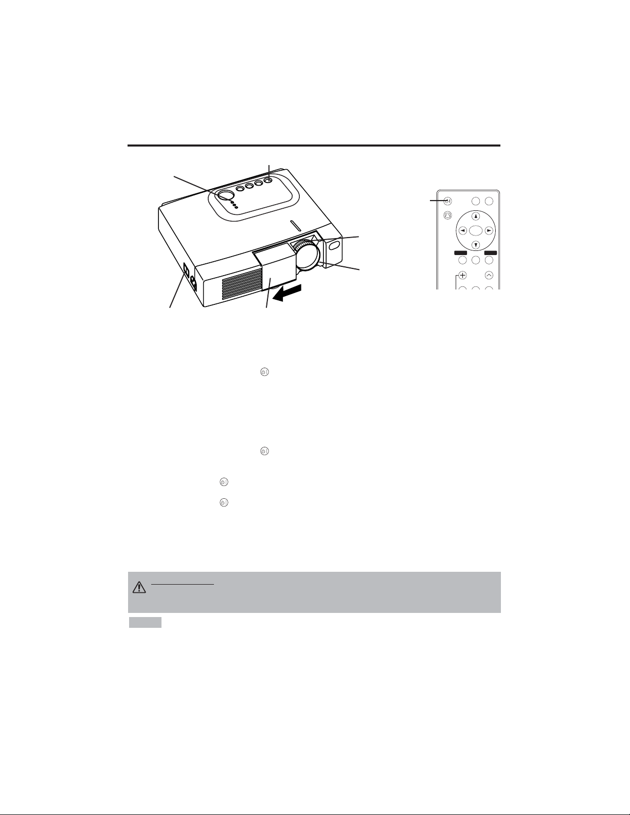
ITALIANO - 8
OPERAZIONI
OPERAZIONI
Attivazione
1. Controllare che il cavo d'alimentazione sia collegato correttamente.
2. Mettere l'interruttore dell'alimentazione su [ | ]. In questa modalità si seleziona la modalità
standby e l'indicatore POWER diventa arancione.
3. Premere il tasto STANDBY/ON sul pannello comandi o sul telecomando. Inizia il
riscaldamento e l'indicatore POWER si accende con luce verde lampeggiante.
4.
L'indicatore
POWER
cessa di lampeggiare e la luce verde diventa fissa quando l'alimentazione è
attivata.
Controllare che l'indicatore sia verde ed aprire lo sportello dell'obiettivo.
5. Ruotare la manopola di regolazione Zoom per regolare la dimensione dello schermo.
6. Ruotare l'anello di messa a fuoco, per regolare la messa a fuoco.
Disattivazione
1. Premere il tasto STANDBY/ON sul pannello comandi o sul telecomando. Poi il messaggio
“Power off?” appare sullo schermo e iil messaggio scompare se si esegue qualsiasi operazione o
nessuna operazione entro 5 secondi. Mentre è visualizzato questo messaggio, premere di nuovo il
tasto STANDBY/ON . La lampada del proiettore si spegne ed inizia a raffreddarsi. L'indicatore
POWER si accende con luce arancione e lampeggia durante il raffreddamento. La pressione del
tasto STANDBY/ON non produce nessun effetto mentre l'indicatore dell'alimentazione
lampeggia.
2. Il sistema passa in modalità Standby al termine del raffreddamento e l'indicatore POWER cessa di
lampeggiare e diventa arancione. Controllare che l'indicatore d'alimentazione sia arancione e
mettere l'interruttore d'accensione su [
O
].
3. L'indicatore POWER si spegne quando l'alimentazione è disattivata. Non dimenticare di chiudere
lo sportello dell'obiettivo.
• Salvo in casi di emergenza, non spegnere se non quando l'indicatore di POWER è di
colore arancione questo per evitare di accorciare la durata di vita della lampada del proiettore.
• Per evitare eventuali problemi, accendere/spegnere il proiettore quando il computer o il
videoregistratore è OFF. Nel caso che sia collegato un cavo RS-232C, accendere il computer prima
del proiettore.
• Quando un proiettore continua a proiettare la stessa immagine, l’immagine può rimanere come
immagine residua. Non proiettare la stessa immagine per lungo tempo.
NOTA
AVVERTENZA • Leggere attentamente il presente manuale e le “ISTRUZIONI
DI SICUREZZA” separate prima di usare l'apparecchiatura. Controllare sempre
che l'apparecchiatura sia usata in condizioni di sicurezza.
Interruttore di alimentazione
Coperchio scorrevole dell'obiettivo
Tasto STANDBY/ON
Indicatore POWER
VIDEO
STANDBY/ON
KEYSTONE
POSITION
FREEZE
MAGNIFY
VOLUME
MENU
SELECT
RGB
MENU RESET
Tasto
STANDBY/ON
Manopla di
regolazione
Zoom
Anello di Focus
Page 82

ITALIANO - 9
ITALIANO
OOPPEERRAAZZIIOONNII((ccoonnttiinnuuaazziioonnee)
)
Operazioni base
Le operazioni base indicate nella Tabella 3 sono eseguite sul telecomando o sul pannello comandi
del proiettore. Le opzioni contrassegnate da un (*) possono essere usate agendo sul pannello
comandi.
Tabella 3. Operazioni base
Opzione Descrizione
INPUT
SELECT
(SELEZIONE
INGRESSI)
Selezione del segnale d'ingresso (*): Premere il tasto INPUT.
RGB → VIDEO → S-VIDEO → COMPONENT (→ RGB )
Selezione dell'ingresso RGB: Premere il tasto RGB.
VIDEO/S-VIDEO/COMPONENT → RGB
Selezione dell'ingresso VIDEO/S-VIDEO: Premere il tasto VIDEO.
RGB → VIDEO/S-VIDEO/COMPONENT
VIDEO → S-VIDEO → COMPONENT (→ VIDEO)
• Il nome del segnale selezionato è visualizzato per circa tre secondi, quando si
cambia il segnale d'ingresso.
POSITION
(POSIZIONE)
Impostazione/Cancellazione della modalità di regolazione posizione:
Premere il tasto POSITION. In modalità POSIZIONE compare l'icona [ ].
Regolazione posizione immagine:
Premere i tasti , , e in modalità regolazione posizione.
• Quando un video segnale è immesso, questa funzione è valida soltanto in modalità
INGRANDIMENTO (MAGNIFY).
• Dopo circa 10 secondi di inattività, l’icona [ ]scompare ed il modo POSITION
viene automaticamente annullato.
RESET (*)
(RESET)
Inizializzazione delle opni opzione: Selezionare un'opzione e premere il tasto RESET.
Inizializzazione della regolazione posizione:
Premere il tasto RESET in modalità
POSIZIONE. Questa funzione è valida soltanto quando il segnale RGB è immesso.
• Abilitato tranne che per VOLUME, LINGUA, FASE H e SILENZIOSO.
MAGNIFY
(INGRANDIMENTO)
Impostazione della modalità INGRANDIMENTO: Premere il tasto MAGNIFY .
Spostamento dell'area ingrandita:
Usare la regolazione della posizione in modalità INGRANDIMENTO.
Regolazione dell'ingrandimento:
Premere i tasti MAGNIFY / in modalità INGRANDIMENTO.
MAGNIFY ingrandisce l’immagine ↔ MAGNIFY rimpicciolisce l’immagine.
Annullamento della modalità INGRANDIMENTO: Premere il tasto MAGNIFY .
• La modalità INGRANDIMENTO si annulla usando o impostando AUTO, LAG./ALT.,
INPUT SELECT o VIDEO, o modificando il segnale d'ingresso.
OFF
FREEZE
(FERMO
IMMAGINE)
Impostazione/Cancellazione della modalità FERMO IMMAGINE: Premere il tasto FREEZE.
Con la modalità FERMO IMMAGINE, sullo schermo appare l'icona [II], e l'immagine si ferma.
• La modalità FERMO IMMAGINE si annulla usando o impostando le modalità POSITION ,
VOLUME, MUTE , AUTO, BLANK ON/OFF , o MENU ON/OFF , oppure ancora modificando il
segnale d'ingresso.
• Non dimenticare di annullare le immagini statiche in situazione di fermo.
KEYSTONE
(*)
Impostazione/annullamento del modo KEYSTONE: Premere il tasto KEYSTONE .
Regolazione della distorsione trapezoidale:
Premere il tasto / nel modo KEYSTONE.
riduce le dimensioni del fondo dell’immagine ↔ riduce le dimensioni della cima
dell’immagine
• Usare il telecomando ad una distanza approssimativa di 3 m dal sensore situato sulla parte anteriore
del proiettore ed entro una fascia sinistra-destra di 30°. Luci forti e ostacoli interferiscono con l'uso del
telecomando.
NOTA
(continua alla pagina seguente)
Page 83

ITALIANO - 10
Opzione Descrizione
VOLUME
(VOLUME)
Regolazione del volume: Premere il tasto VOLUME
/
.
Per ridurre il VOLUME ↔ Per aumentare il VOLUME
MUTE
(SILENZIAMENTO)
Impostazione/Cancellazione della modalità Mute: Premere il tasto MUTE.
In modalità SILENZIAMENTO non si percepisce nessun suono.
AUTO
(AUTO)
Regolazione automatica sull'ingresso RGB: Premere il tasto AUTO.
La posizione orizzontale (POSIZ H), la posizione verticale (POSIZ V), la
fase di sincronizzazione (FASE H), e la dimensione orizzontale (FORM. H)
sono regolate automaticamente. Usare con la finestra più grande del
display delle applicazioni.
Regolazione automatica sull'ingresso VIDEO: Premere il tasto AUTO.
Il tipo di segnale appropriato per il segnale d'ingresso è selezionato
automaticamente. Questa funzione è valida solo quando nel menu degli
ingressi l'opzione AUTO è stata impostata su VIDEO.
• Quest'operazione richiede circa dieci secondi. Può non funzionare correttamente
con alcuni segnali d'ingresso.
BLANK
ON/OFF
(ATTIVAZIONE/DIS
ATTIVAZIONE
SOPPRESSIONE
IMMAGINE)
Impostazione/Cancellazione della modalità Blank:
Premere il tasto BLANK. Nessun'immagine è visualizzata in modalità Blank.
Il colore dello schermo è quello impostato nel menu SP. VUOTO.
MENU
ON/OFF (*)
(ATTIVAZIONE/
DISATTIVAZIO
NE MENU)
Avvio/arresto visualizzazione del menu: Premere il tasto MENU.
• La visualizzazione del menu termina automaticamente dopo circa dieci
secondi d'inattività.
MENU
SELECT
(SELEZIONE
MENU)
Selezione del tipo di menu: Premere il tasto MENU SELECT. Questa
funzione permette all'utente di selezionare il menu normale o quello
individuale. Il menu individuale visualizza solo l'opzione scelta, mentre le
altre opzioni si possono visualizzare agendo sui tasti e , come avviene
con i menu normali.
• Utilizzabile solo quando si usa il Menu Prep. Premere il pulsante MENU SELECT
dopo aver selezionato le opzioni, quali "LUMIN." .
Menu normale Menu Individuale
OOPPEERRAAZZIIOONNII((ccoonnttiinnuuaazziioonnee)
)
Le opzioni contrassegnate da un (*) possono essere usate agendo sul pannello comandi.
Tabella 3. Operazioni base (continuazione)
CONTRASTO
-2
LUMIN.
CONTRASTO
POSIZ V
POSIZ H
FASE H
FORM. H
COL EQUIL R
COL EQUIL B
LARG. /ALT.
0
-2
+1
0
0
100
100
800
PREP. IMMET OPZ.IMMAG
(MENU SELECT)
Page 84

ITALIANO - 11
ITALIANO
OOPPEERRAAZZIIOONNII((ccoonnttiinnuuaazziioonnee)
)
Menu Prep.
La selezione di PREP. all'inizio del menu permette di eseguire le regolazioni e le impostazioni
elencate nel seguito. Una parte del menu Setup è diversa secondo che si usi l'ingresso RGB o
l'ingresso VIDEO/S-VIDEO. Selezionare un'opzione con i tasti e , ed iniziare l'operazione.
Usare il Menu individuale per ridurre la dimensione del menu (vedere Tabella 3, MENU SELECT).
LUMIN.
CONTRASTO
POSIZ V
POSIZ H
FASE H
FORM. H
COL EQUIL R
COL EQUIL B
LARG. /ALT.
0
-2
+1
0
0
100
100
800
PREP. IMMET OPZ.IMMAG
LUMIN.
CONTRASTO
COLORE
FASE H
COL EQUIL R
COL EQUIL B
LARG. /ALT.
0
+1
+1
0
0
0
PREP. IMMET OPZ.IMMAG
LUMIN.
CONTRASTO
NITIDEZZA
COLORE
CHIARI
COL EQUIL R
COL EQUIL B
LARG. /ALT.
0
+1
+1
0
0
0
0
PREP. IMMET OPZ.IMMAG
Tabella 4. Menu Prep.
VIDEO/S-VIDEO
COMPONENT
RGB
Opzione Descrizione
RGB
VIDEO
S-VIDEO
COMPONENT
480i
575i
480P
720P
1080i
LUMIN.
Scuro ↔ Chiaro
✔ ✔ ✔ ✔
CONTRASTO
Debole ↔ Forte
✔ ✔ ✔ ✔
POSIZ V
Giù ↔ Su
✔
- - -
POSIZ H
Sinistra ↔ Destra
✔
- - -
FASE H
Sinistra ↔ Destra
• Regolare per eliminare il tremolio d'immagine.
✔
-
✔ ✔
FORM. H
Piccolo ↔ Grande
•
La visualizzazione dell'immagine può non essere corretta,
se la dimensione orizzontale è eccessiva. In questo caso,
premere il tasto RESET ed inizializzare la dimensione
orizzontale.
✔
- - -
NITIDEZZA
Tenue ↔ Nitido
-
✔
- -
COLORE
Chiaro ↔ Scuro
-
✔ ✔ ✔
CHIARI
Rosso ↔ Verde
• Utilizzabile solo quando si ricevono i segnali NTSC o
NTSC 4.43.
-
✔
- -
COL EQUIL R
Chiaro ↔ Scuro
✔ ✔ ✔ ✔
COL EQUIL B
Chiaro ↔ Scuro
✔ ✔ ✔ ✔
LARG. /ALT.
Selezionare il rapporto tra la larghezza e l'altezza
dell'immagine:4:3[ ] ↔ 16:9[ ]
Selezionare posizione display:
Premere il tasto mentre si seleziona 16:9[ ].
Centro → Giù → Su ( → Centro)
✔
- -
✔
Selezionare il rapporto tra la larghezza e l'altezza
dell'immagine:
4:3
[]
↔ 16:9
[]
↔ 4:3 piccolo
[]
Selezionare posizione display:
Premere il tasto mentre si seleziona 16:9
[]
/ 4:3
piccolo
[]
.
Centro → Giù → Su ( → Centro)
• Con alcuni segnali d'ingresso la visualizzazione di 4:3
piccolo può non essere corretta.
-
✔ ✔
-
Page 85

ITALIANO - 12
OOPPEERRAAZZIIOONNII((ccoonnttiinnuuaazziioonnee)
)
Menu Immet
La scelta di IMMET nel menu mette a disposizione le funzioni elencate nel
seguito. Selezionare un'opzione con i tasti e , ed iniziare
l'operazione.
Tabella 5. Menu Immet
ESEGUI
CANCELLAR
AUTO
RGB
VIDEO
HDTV
PREP. IMMET OPZ.IMMAG
Opzione Descrizione
AUTO
Avvio/arresto dell'operazione: Premere il tasto / .
Regolazione automatica sull'ingresso RGB:
Selezionare ESEGUI con il tasto . La posizione orizzontale (POSIZ H), la
posizione verticale (POSIZ V), la fase di sincronizzazione (FASE H), e la
dimensione orizzontale (FORM. H) sono regolate automaticamente. Usare
con la finestra più grande del display delle applicazioni.
• Quest'operazione richiede circa dieci secondi. Con alcuni segnali d'ingresso può
non funzionare correttamente. In questo caso, la pressione del tasto AUTO può
correggere questo problema.
• Questa funzione è la stessa della funzione AUTO relativa al funzionamento basico.
RGB
Visualizzazione della frequenza dell'ingresso RGB:
Visualizza la frequenza del segnale di sincronizzazione orizzontale e
verticale per l'ingresso RGB.
• Utilizzabile solo con ingresso RGB.
VIDEO
Avvio/arresto dell'operazione: Premere il tasto / .
Selezione del tipo di segnale video:
Selezionare il tipo di segnale con i tasti e . Selezionare NTSC, PAL,
SECAM, NTSC4.43, M-PAL, o N-PAL in funzione del segnale d'ingresso.
Ad eccezione del formato di ingresso N-PAL, la selezione di AUTO abilita e
rende esecutiva la funzione AUTO (adattamento automatico all’ingresso
video).
•
l Questa funzione va usata qualora agli ingressi VIDEO/S-VIDEO l’immagine divenga
instabile (ad esempio qualora presenti delle irregolarità oppure sia priva di colori).
• l L’adattamento automatico richiede circa dieci secondi. Tuttavia potrebbe non
funzionare correttamente con alcuni tipi di segnale. In questo caso, ad eccezione del
formato di ingresso N-PAL, premendo il pulsante AUTO si può risovere il problema.
• l Questa funzione non è operativa in caso di ingresso COMPONENT VIDEO ed il
segnale viene automaticamente riconosciuto.
HDTV
Avvio/arresto dell'operazione: Premere il tasto / .
Selezione del modo HDTV: Con i pulsanti / selezionate il modo
1080i oppure il modo 1035i più appropriati al segnale di ingresso.
• Quando il modo HDTV selezionato è incompatibile con il segnale in ingresso,
l’immagine può non essere corretta (p.es. la posizione di visualizzazione o il colore
non sono corretti).
Page 86
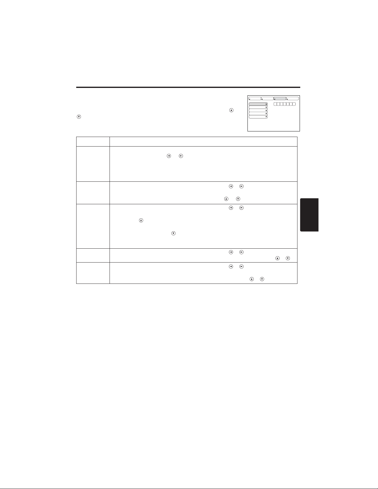
ITALIANO - 13
ITALIANO
OOPPEERRAAZZIIOONNII((ccoonnttiinnuuaazziioonnee)
)
Menu Immagine
La selezione di IMAGE nel menu permette di eseguire le regolazioni e le
impostazioni elencate nel seguito. Selezionare un'opzione con i tasti e
, ed iniziare l'operazione.
Tabella 6. Menu Immagine
SP.VUOTO
SPECCHIO
AVVIARE
GAMMA
COLOR TEMP
PREP. IMMET OPZ.IMMAG
Opzione Descrizione
SP.VUOTO
Selezione del colore dello schermo senza immagine:
Selezionare con i tasti e .
• L'immagine è cancellata e tutto lo schermo intero è esposto nel colore selezionato,
quando il modalità BLANK (MODALITÀ SOPPRESSIONE IMMAGINE) è impostato
con BLANK ON (SOPPRESSIONE ATTIVA), o quando non vi è nessun segnale per
5 minuti.
SPECCHIO
Avvio/arresto dell'operazione: Premere i tasti / .
Selezione della condizione di Specchio:
Selezionare la condizione specchio con i tasti e .
AVVIARE
Avvio/arresto dell'operazione: Premere i tasti / .
Impostazione visualizzazione schermo iniziale: Selezionare ACCEN.RE
con il tasto .
Cancellazione della visualizzazione dello schermo iniziale: Selezionare
SPEGNERE con il tasto .
• Notare che se è stato selezionato SPEGNERE quando non si riceve il segnale, lo
schermo vuoto appare blu.
GAMMA
Avvio/arresto dell'operazione: Premere i tasti / .
Selezione della
modo
gamma: Selezionare la modo gamma con il tasto
/ .
COLOR
TEMP
Avvio/arresto dell'operazione: Premere i tasti / .
Selezioni la Tempratura di colore:
Selezionare il modo di temperatura del colore con i
tasto
/ .
Page 87

ITALIANO - 14
OOPPEERRAAZZIIOONNII((ccoonnttiinnuuaazziioonnee)
)
Menu Opzioni
La selezione di OPZ. nel menu permette di eseguire le regolazioni e
le impostazioni elencate nel seguito. Selezionare un'opzione con i
tasti e , ed iniziare l'operazione.
Tabella 7. Menu Opzioni
VOLUME
COLORE MENU
LINGUA
AUTO OFF
SYNC ON G
SILENZIOSO
16
PREP. IMMET OPZ.IMMAG
Opzione Descrizione
VOLUME
Regolazione del volume:
Per ridurre il VOLUME
↔ Per aumentare il VOLUME
COLORE
MENU
Selezione del colore del fondo del menu:
Selezionare con i tasti e .
LINGUA
Avvio/arresto dell'operazione: Premere il tasto o .
Selezione della lingua del menu: Selezionare con i tasti e .
AUTO OFF
Avvio/arresto dell'operazione: Premere il tasto o .
Impostazione di AUTO OFF: Impostare 1~99 minuti con i tasti e .
Il sistema entra automaticamente in modalità standby, quando non
riceve il segnale per il tempo impostato.
Annullamento di AUTO OFF: Selezionare CANCEL (0 min.) con il tasto
.
La selezione di CANCEL non permette al sistema di accedere alla
modalità standby anche se non riceve segnali.
SYNC ON G
Avvio/arresto dell'operazione: Premere i tasti o .
SYNC ON G valido: Selezionare ACCEN.RE con il tasto .
SYNC ON G non valido: Selezionare SPEGNERE con il tasto .
• Con alcuni segnali d'ingresso la visualizzazione può non essere
corretta quando è stata attivata la modalità SYNC ON G . In questo
caso, togliere il connettore dei segnali affinché l'apparecchio riceva il
segnale, impostare SYNC ON G su disattivo e ricollegare il segnale.
SILENZIOSO
Avvio/arresto dell'operazione: Premere i tasti / .
Impostazione/annullamento del modo SILENZIOSO:
Premere il tasto / .
Quando è selezionato SILEZIOSO, il modo SILEZIOSO è attivo. Nel
modo SILEZIOSO, il livello di rumore acustico prodotto dall’unità viene
ridotto, il livello di luminosità dello schermo è leggermente inferiore.
Page 88

ITALIANO - 15
ITALIANO
OOPPEERRAAZZIIOONNII((ccoonnttiinnuuaazziioonnee)
)
Menu Nessun segnale
È possibile eseguire le stesse regolazioni ed impostazioni dei menu
IMAGE e OPZ. quando si preme il tasto MENU durante la
visualizzazione del messaggio “
NESSUN INGRESSO RIV.SU ***”
o “
SINCRON. FUPRI GAMMA SU ***”, e non si riceve nessun
segnale.
Tabella 8. Menu Nessun segnale
VOLUME
SP.VUOTO
SPECCHIO
AVVIARE
COLORE MENU
LINGUA
AUTO OFF
SYNC ON G
SILENZIOSO
16
Opzione Descrizione
VOLUME
Regolazione del volume: Per ridurre il VOLUME ↔ Per aumentare il VOLUME
• Quando questa funzione viene utilizzata, l’ingresso audio viene
automaticamente commutato su video. L’ingresso audio può essere commutato
muovendo il tasto a disco (DISK PAD) verso destra o sinistra durante la
visualizzazione della barra di regolazione del volume. Quest’ultima viene
visualizzata premendo i pulsanti VOLUME o VOLUME .
SP.VUOTO
Selezione del colore dello schermo senza immagine: Selezionare con i tasti e .
• L'immagine è cancellata e tutto lo schermo intero è esposto nel colore
selezionato, quando il modalità BLANK (MODALITÀ SOPPRESSIONE
IMMAGINE) è impostato con BLANK ON (SOPPRESSIONE ATTIVA), o quando
non vi è nessun segnale per 5 minuti.
SPECCHIO
Avvio/arresto dell'operazione: Premere i tasti /
Selezione della condizione di Specchio:
Selezionare la condizione specchio con i tasti e .
AVVIARE
Avvio/arresto dell'operazione: Premere i tasti / .
Impostazione visualizzazione schermo iniziale: Selezionare ACCEN.RE con il tasto .
Cancellazione della visualizzazione dello schermo iniziale:
Selezionare SPEGNERE con il tasto .
• Notare che se è stato selezionato SPEGNERE quando non si riceve il segnale, lo schermo
vuoto appare blu.
COLORE MENU
Selezione del colore del fondo del menu: Selezionare con i tasti e .
LINGUA
Avvio/arresto dell'operazione: Premere il tasto / .
Selezione della lingua del menu: Selezionare con i tasti e .
AUTO OFF
Avvio/arresto dell'operazione: Premere il tasto / .
Impostazione di AUTO OFF: Impostare 1~99 minuti con i tasti e .
Il sistema entra automaticamente in modalità standby, quando non riceve il segnale per il
tempo impostato.
Annullamento di AUTO OFF: Selezionare CANCEL (0 min.) con il tasto .
La selezione di CANCEL non permette al sistema di accedere alla modalità standby anche
se non riceve segnali.
SYNC ON G
Avvio/arresto dell'operazione: Premere i tasti / .
SYNC ON G valido: Selezionare ACCEN.RE con il tasto .
SYNC ON G non valido: Selezionare SPEGNERE con il tasto .
• Con alcuni segnali d'ingresso la visualizzazione può non essere corretta quando è stata
attivata la modalità SYNC ON G. In questo caso, togliere il connettore dei segnali affinché
l'apparecchio riceva il segnale, impostare SYNC ON G su disattivo e ricollegare il segnale.
SILENZIOSO
Avvio/arresto dell'operazione: Premere i tasti / .
Impostazione/annullamento del modo SILENZIOSO: Premere il tasto / .
Quando è selezionato SILEZIOSO, il modo SILEZIOSO è attivo. Nel modo SILEZIOSO, il
livello di rumore acustico prodotto dall’unità viene ridotto, il livello di luminosità dello schermo
è leggermente inferiore.
Page 89
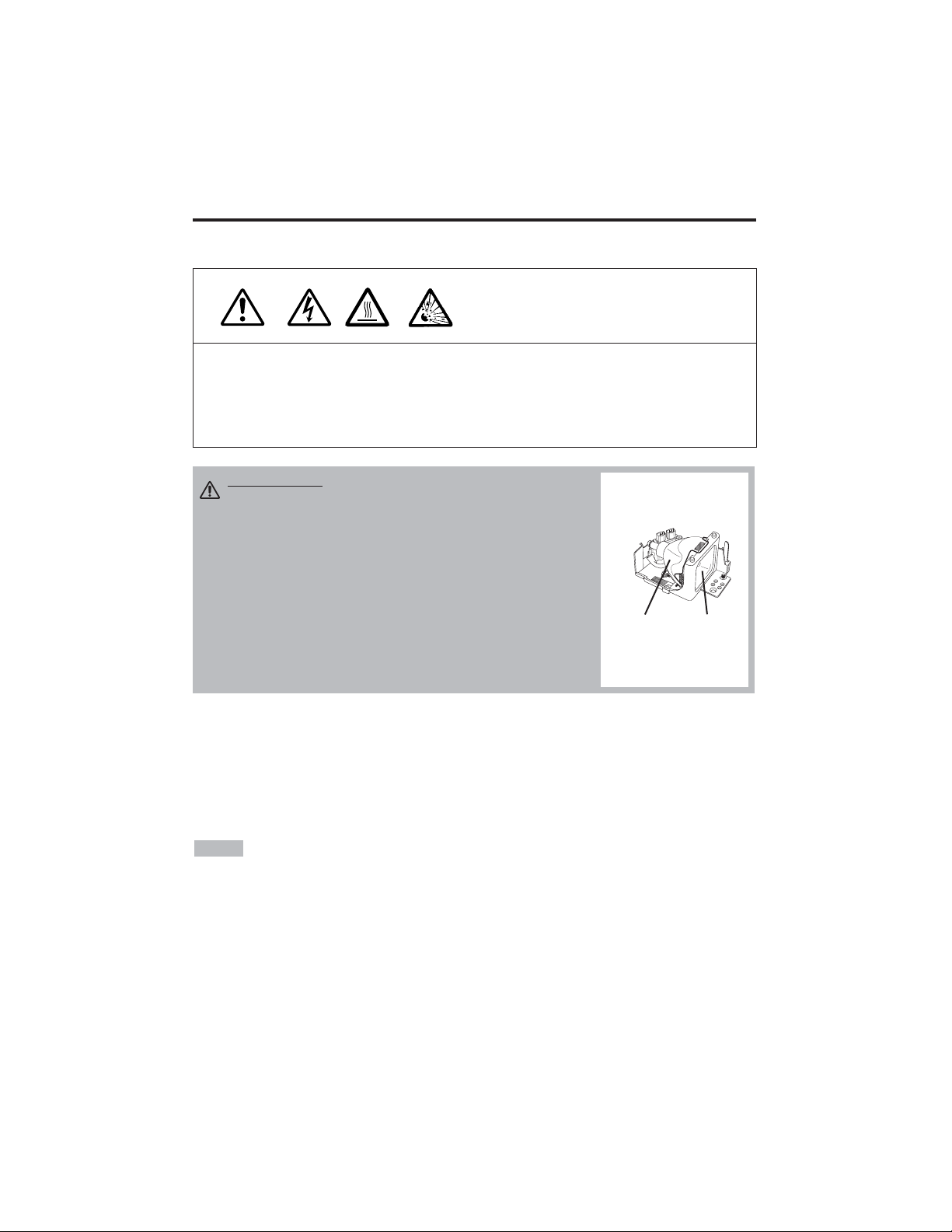
ITALIANO - 16
MANUTENZIONE
MANUTENZIONE
Lampada
ALTA TENSIONE
ALTA TEMPERATURA
ALTA PRESSIONE
Rivolgersi al proprio rivenditore prima di sostituire la lampada.
Per quanto riguarda la lampada opzionale, preghiamo di vedere la voce "Parti Opzionali" della
Tabella 12.
Spegnere l'apparecchiatura, scollegare il cavo d'alimentazione dalla presa e attendere circa 45
minuti per permettere alla lampada di raffreddarsi, prima di sostituirla. La lampada può esplodere
se maneggiata ancora calda.
Durata della lampada
Le lampade del proiettore hanno una durata determinata. L'immagine diventerà scura e le tonalità
cromatiche si attenueranno progressivamente, dopo un lungo periodo d'uso della lampada.
Sostituire la lampada quando l'indicatore LAMP è rosso o all'accensione del proiettore compare
sullo schermo il messaggio CAMBIARE LA LAMPADA. Fate riferimento alla Tavola 9 di pag. 19
e alla Tavola 10 di pag. 20.
• L'indicatore LAMP è rosso anche quando la lampada raggiunge temperature elevate.
Spegnere l'apparecchiatura, attendere circa 20 minuti e riaccendere l'apparecchiatura, prima di
sostituire la lampada. Se l'indicatore LAMP è ancora rosso, sostituire la lampada.
NOTA
AVVERTENZA • Smaltire le lampade usate in
conformità alle normative locali in vigore.
• Le lampada sono di vetro, quindi non devono essere
rigate o sottoposte a urti meccanici.
• Non riutilizzare vecchie lampade - potrebbero esplodere.
• Nel caso la lampada esploda (percezione di un suono
d'esplosione), scollegare la spina dalla presa e rivolgersi
al rivenditore per la sostituzione della lampada. La
lampada è coperta da un vetro anteriore, ma in alcuni rari
casi, il riflettore e la parte interna del proiettore possono
essere danneggiati dai pezzi di vetro che si sparpagliano
all'interno e che possono provocare lesioni.
• Non usare il proiettore privo del coperchio della lampada.
Lampada
Vetro
anteriore
Reflettore
Page 90

ITALIANO - 17
ITALIANO
MMAANNUUTTEENNZZIIOONNEE((ccoonnttiinnuuaazziioonnee)
)
Sostituzione della lampada
1. Spegnere il proiettore, scollegare il cavo d'alimentazione dalla
presa ed attendere almeno 45 minuti per permettere all'unità di
raffreddarsi.
2. Preparare una nuova lampada.
3. Controllare che il proiettore sia sufficientemente freddo e
capovolgerlo con attenzione.
4. Svitare le due viti come mostrato in figura e rimuovere il coperchio
della lampada.
5. Svitare l’unica vite e, con cura, rimuovere la lampada afferrando le
impugnature. Toccare l'interno dell'involucro della lampada può
provocare una colorazione non uniforme.
6. Montare la nuova lampada e serrare saldamente la vite di fermo
della stessa. Spingere energicamente nell'unità anche il lato opposto
della lampada avvitata.
7. Rimettere a posto il coperchio della lampada e serrare bene le due
viti.
8. Rigirare il proiettore con cautela.
Ripristino del timer della lampada
Ripristinare il timer della lampada dopo aver sostituito quest’ultima. Terminare le operazioni sotto
descritte entro 10 minuti dallo spegnimento dell’apparecchiatura, se sullo schermo è comparso il
messaggio “CAMBIARE LA LAMPADA … L’UNITÀ VIENE SPENTA DOPO 0 ORE.”.
L’alimentazione sarà riattivata automaticamente 10 minuti dopo lo spegnimento.
1. Accendete il proiettore agendo sull’interruttore ON e quindi premete il pulsante RESET per circa
tre secondi. Il messaggio 'LAMP xxxx hr' comparirà sul timer della lampada, nella parte bassa
dello schermo.
2. Premere il tasto MENU sul telecomando, o il tasto RESET sul pannello comandi, mentre il timer
della lampada è visualizzato. Il messaggio ‘LAMP xxxx
→ 0 ■ CANCEL’ comparirà sullo
schermo.
3. Premere il tasto , selezionare 0 ed attendere quindi fino alla cancellazione del display timer.
• Non ripristinare il timer della lampada senza aver sostituito quest'ultima. Ripristinare
sempre il timer della lampada dopo aver sostituito la lampada. Le funzioni di messaggio non
funzioneranno correttamente se il timer della lampada non sarà stato ripristinato.
NOTA
ATTENZIONE • Controllare che le viti siano ben
serrate. Le viti non correttamente serrate possono
essere causa di lesioni o d'incidenti.
• Non usare il proiettore privo del coperchio della
lampada.
Page 91

ITALIANO - 18
MMAANNUUTTEENNZZIIOONNEE((ccoonnttiinnuuaazziioonnee)
)
Manutenzione del filtro dell'aria
Il filtro dell'aria deve essere pulito come descritto nel seguito all'incirca ogni 100 ore.
1. Spegnere il proiettore e scollegare il cavo d'alimentazione dalla presa.
2. Pulire il filtro dell'aria con un aspirapolvere.
Altri interventi di manutenzione
Manutenzione all'interno dell'apparecchiatura
Per motivi di sicurezza, far controllare e pulire l'apparecchiatura dal rivenditore ogni due anni. La
manutenzione eseguita personalmente è pericolosa.
Pulizia dell'obiettivo
Non ripristinare il timer della lampada senza aver sostituito quest'ultima. Ripristinare sempre il
timer della lampada dopo aver sostituito la lampada. Le funzioni di messaggio non funzioneranno
correttamente se il timer della lampada non sarà stato ripristinato.
Pulizia della parte esterna dell'apparecchio e del telecomando
Pulire con delicatezza usando un panno morbido. In caso sia difficile rimuovere lo sporco o le
macchie, etc. usare un panno morbido inumidito con acqua o con detergente neutro diluito in acqua,
quindi asciugare perfettamente con un altro panno morbido.
ATTENZIONE • Spegnere l'apparecchiatura e scollegare il cavo
d'alimentazione dalla presa, prima di iniziare un intervento manutentivo.
Leggere attentamente le “ISTRUZIONI DI SICUREZZA” separate per essere certi
che l'intervento manutentivo sia eseguito correttamente.
• Sostituire il filtro dell'aria se gli agenti contaminanti non possono essere
asportati o se il filtro è danneggiato. Rivolgersi al proprio rivenditore. Per quanto
riguarda il filtro aria opzionale, preghiamo di vedere la voce "Parti Opzionali"
della Tabella 12.
• Non usare l'apparecchiatura priva del filtro dell'aria.
• Quando il filtro dell'aria è intasato dalla polvere sullo l'alimentazione si scollega
automaticamente per evitare l'aumento della temperatura all'interno del
proiettore.
ATTENZIONE • Spegnere l'apparecchiatura e scollegare il cavo
d'alimentazione dalla presa, prima di iniziare un intervento manutentivo.
Leggere attentamente le “ISTRUZIONI DI SICUREZZA” separate per essere certi
che l'intervento manutentivo sia eseguito correttamente.
• Non usare detergenti o prodotti chimici diversi da quelli sopra indicati (per
esempio: benzene o diluenti).
• Non usare spray detergenti.
• Non sfregare con oggetti duri, né battere l'apparecchiatura.
Page 92

ITALIANO - 19
ITALIANO
RISOLUZIONE DEI PROBLEMI
RISOLUZIONE DEI PROBLEMI
Messaggio OSD
I messaggi riportati nel seguito possono essere visualizzati sullo schermo al momento
dell'accensione dell'apparecchiatura. Prendere le adeguate misure ogni volta che appaiono detti
messaggi.
Tabella 9. Messaggio OSD
Messaggio Descrizione
CAMBIARE LA LAMPADA
SOSTITUITA LA LAMPADA,
AZZERARE IL TIMER
DELLA LAMPADA.
(*1)
Il tempo di impiego della lampada sta per raggiungere 2000
ore. (*2)
Si consiglia di sostituire presto la lampada. Preparare una
nuova lampada di ricambio.
CAMBIARE LA LAMPADA
SOSTITUITA LA LAMPADA,
AZZERARE IL TIMER
DELLA LAMPADA.
L’UNITÀ VIENE SPENTA
DOPO ** ORE.
(*1)
Il tempo di impiego della lampada sta per raggiungere 2000
ore. Si consiglia di sostituire la lampada entro ** ore. (*2)
Può succedere che la lampada cessi di funzionare prima che
siano trascorse ** ore. L’alimentazione sarà interrotta
automaticamente in ** ore. Sostituire la lampada come
indicato a p.17-18 "Lampada". Azzerare sempre il timer della
lampada dopo aver sostituito la lampada.
CAMBIARE LA LAMPADA
SOSTITUITA LA LAMPADA,
AZZERARE IL TIMER
DELLA LAMPADA.
L’UNITÀ VIENE SPENTA
DOPO 0 ORE.
Il tempo di impiego della lampada sta per raggiungere.
L’alimentazione sarà interrotta tra pochi minuti. (*2)
Spegnere immediatamente e sostituire la lampada come
indicato a p.17-18 "Lampada".
Azzerare sempre il timer della lampada dopo aver sostituito
la lampada.
NESSUN INGRESSO RIV.
SU ***
Non vi è nessun segnale in ingresso.
Controllare i collegamenti d'ingresso e le sorgenti del
segnale.
SINCRON. FUPRI GAMMA
SU ***
La frequenza orizzontale o verticale del segnale d'ingresso
non è compresa nella fascia specificata
Controllare i dati tecnici dell'apparecchiatura e le sorgenti del
segnale.
CONTROLL FLUSSO AIRA
La temperatura interna è aumentata.
Spegnere l'apparecchiatura ed attendere 20 minuti affinché
l'apparecchiatura si raffreddi.
Eseguire le seguenti verifiche e riaccendere
l'apparecchiatura.
• Verificare se l'ingresso o l'uscita dell'aria sono bloccati ?
• Verificare se il filtro dell'aria è sporco ?
• Verificare se la temperatura ambiente supera i 35°C ?
(*1) Questo messaggio si cancella automaticamente dopo circa tre minuti e ricompare
ogni volta che si accende l'apparecchiatura.
(*2) L’unità dispone di una funzione che disattiva l’alimentazione quando il tempo di impiego
raggiunge 2000 ore. Tuttavia la vita utile della lampada può variare notevolmente da una lampada
all’altra, per cui può succedere che una lampada cessi di funzionare prima che si attivi questa
funzione.
NOTA
Page 93

ITALIANO - 20
RRIISSOOLLUUZZIIOONNEEDDEEIIPPRROOBBLLEEMMII((ccoonnttiinnuuaazziioonnee)
)
Messaggio degli indicator
L'indicatore POWER, quello LAMP e quello TEMP si accendono e si spengono come segue.
Adottare le misure appropriate.
Tabella 10. Messaggio degli indicator
Indicatore
POWER
Indicatore
LAMP
Indicatore
TEMP
Descrizione
Si illumina in
arancione
Si spegne Si spegne È stata impostata la modalità Standby.
Lampeggia in
verde
Si spegne Si spegne Riscaldamento. Attendere.
Si illumina in
verde
Si spegne Si spegne ACCESA. È possibile il funzionamento normale.
Lampeggia in
arancione
Si spegne Si spegne Raffreddamento. Attendere.
Lampeggia in
rosso
- -
Raffreddamento. Attendere.
L'errore è trovato. Adottare le misure appropriate quando
l'indicatore POWER cessa di lampeggiare.
Lampeggia/si
illumina in
rosso
Si illumina
in rosso
Si spegne
La lampada non è accesa.
L'interno dell'apparecchiatura può essere troppo caldo.
Spegnere l'apparecchiatura, attendere 20 minuti affinché si
raffreddi e verificare se l'ingresso o l'uscita sono bloccati, se il
filtro dell'aria è sporco o se la temperatura ambiente è
superiore a 35°C. Quindi riaccendere l'apparecchiatura.
Sostituire la lampada se il problema si ripresenta.
Lampeggia/si
illumina in
rosso
Lampeggi
a in rosso
Si spegne
Manca la lampada o il coperchio della stessa, o non è stata
montata correttamente.
Spegnere l'apparecchiatura ed attendere 45 minuti affinché si
raffreddi. Controllare l'installazione della lampada ed il
coperchio della stessa, quindi riaccendere l'apparecchiatura.
Rivolgersi al proprio rivenditore se il problema si ripresenta.
Lampeggia/si
illumina in
rosso
Si spegne
Lampeggi
a in rosso
La ventola di raffreddamento non funziona.
Spegnere l'apparecchiatura ed attendere 20 minuti affinché si
raffreddi. Controllare che non vi siano corpi estranei nella
ventola e riaccendere l'apparecchiatura. Rivolgersi al proprio
rivenditore se il problema si ripresenta.
Lampeggia/si
illumina in
rosso
Si spegne
Si illumina
in rosso
L'interno dell'apparecchiatura è troppo caldo. *2)
Spegnere l'apparecchiatura ed attendere 20 minuti affinché si
raffreddi. Verificare se l'ingresso o l'uscita sono bloccati, se il
filtro dell'aria è sporco o se la temperatura ambiente è
superiore a 35°C. Riaccendere quindi l'apparecchiatura.
Rivolgersi al proprio rivenditore se il problema si ripresenta.
Si illumina in
verde
Lampeggia
in rosso
Lampeggia
in rosso
L’interno dell’unità è troppo freddo.
Controllare se la temperatura ambientale è inferiore a 0°C.
Contattare il rivenditore se questo problema si verifica quando
la temperatura ambientale è 0-35°C.
*2) Per motivi di sicurezza l'alimentazione si disattiva automaticamente e l'indicatore si
spegne, quando la temperatura interna diventa eccessiva . Mettere l'interruttore d'alimentazione su
[
O
] ed attendere 20 minuti affinché l'apparecchiatura si raffreddi.
NOTA
Page 94

ITALIANO - 21
ITALIANO
RRIISSOOLLUUZZIIOONNEEDDEEIIPPRROOBBLLEEMMII((ccoonnttiinnuuaazziioonnee)
)
Sintomo
Gli eventi sotto elencati spesso appaiono come anomalie.
Questi eventi possono non essere anomalie. Controllare seguendo la tabella sotto riportata.
Tabella 11. Sintomo
Evento Esempi di non anomalia Punti da verificare Pagina
L'alimentazione
non è attivata.
L’interruttore dell’alimentazione
elettrica non è stato attivato.
Attivare l’interruttore
dell’alimentazione elettrica.
7,8
Il cavo di alimentazione non è
ben sistemato.
Inserire il cavo di alimentazione
nella presa di corrente a CA.
Assenza di video
o di audio.
L’ingresso non è correttamente
impostato.
Effettuare l’impostazione utilizzando il
proiettore o il telecomando.
9
Non vi è presenza di alcun
ingresso di segnale.
Collegare in modo adeguato. 6,7
Il video è
funzionante, ma vi
è assenza di audio
Il proiettore non è
adeguatamente collegato.
Collegare in modo adeguato. 6,7
Il volume è impostato al minimo.
Premere VOLUME sul
telecomando o visualizzare la
schermata del menu, quindi
regolare il volume.
10,14
E’ attivata la funzione di
esclusione audio.
Premere il tasto MUTE .
10
Video è presente
ma non il video.
Il proiettore non è stato
collegato in modo corretto.
Collegare in modo corretto. 6,7
La luminosità è impostata sul
minimo.
Selezionare LUMIN. con il pulsante
MENU e premere il tasto .
11
Lo sportello scorrevole
dell'obiettivo è sempre chiuso.
Aprire lo sportello scorrevole
dell'obiettivo.
8
I colori sono pallidi
e la corrispondenza
cromatica è scarsa.
La densità e la simulazione dei
colori non sono correttamente
regolate.
Regolare il video. 11
Le immagini sono
scure.
La luminosità ed il contrasto non
sono regolati in modo adeguato
Regolare il video. 11
La durata della lampada si sta
esaurendo.
Sostituire con una nuova lampada. 16,17
Le immagini sono
sfocate.
La messa a fuoco o la FASE H
non rientrano nei valori di
regolazione.
Regolare la messa a fuoco o la
FASE H.
8,11
Page 95

ITALIANO - 22
DATI TECNICI
DATI TECNICI
Tabella 12 Dati tecnici
• I presenti dati tecnici sono soggetti a modifiche senza preavviso.
NOTA
Articolo Dati tecnici
Denominazione prodotto Proiettore a cristalli liquidi
Pannello a
cristalli
liquidi
Dimensione pannello 1,8 cm (tipo 0,7)
Sistema di comando matrice attiva TFT
Pixel
CP-S225W : 480.000 pixel (800 orizzontale x 600 verticale)
CP-X275W : 786.432 pixel (1024 orizzontale x 768 verticale)
Obiettivo Obiettivo zoom F=2,0 ~ 2,3 f= 18 ~ 21 mm
Lampada 150 W UHB
Altoparlante 1,0 W
Alimentazione 100 ~ 120 V c.a., 2,7 A / 220 ~ 240 V c.a., 1,3 A
Potenza assorbita
240 W
Fascia di temperatura
0 ~ 35°C (Funzionamento)
Dimensione
289 (L) x 84 (A) x 215 (P) mm
Peso (massa)
CP-S225W : 2,4 kg
CP-X275W : 2,5 kg
Ingresso
segnale
RGB
RGB IN
Video: Analogico 0,7 Vp-p, 75 Ω terminale (positivo)
Sincronizzazione O/V: livello TTL (positivo/negativo)
Sincronizzazione composta: livello TTL
Presa a 15 pin D-sub
AUDIO IN
200 mVrms, 47 kΩ (max. 3,0 Vp-p)
Mini presa stereo
Ingresso di
segnale
video
VIDEO 1,0 Vp-p, 75 Ω terminale Presa RCA
S-VIDEO
Segnale di luminosità: 1,0 Vp-p 75 Ω terminale
Segnale cromatico: 0,286 Vp-p (NTSC, segnale burst), 75 Ω terminale
0,3 Vp-p (PAL/SECAM, segnale burst), 75 Ω terminale
Presa a 4 pin mini DIN
COMPONENT
VIDEO
Y 1,0 Vp-p, 75 Ω terminale (positivo)
CB/CR 0,7 Vp-p, 75 Ω terminale (positivo)
PB/PR 0,7 Vp-p, 75 Ω terminale (positivo)
AUDIO
L
200 mVrms, 47 kΩ (max. 3,0 Vp-p)
Presa RCA
R
Funzioni di
comando
CONTROL Presa a 15 pin D-sub
Parti Opzionali
Lampada: DT00401 (CP-S225W) / DT00461 (CP-X275W)
Filtro Aria: MU01461
* Per altre parti vi preghiamo di rivolgervi al vostro rivenditore.
Page 96

ITALIANO - 23
ITALIANO
GARANZIA E ASSISTENZA
GARANZIA E ASSISTENZA
In caso di problemi con l'apparecchiatura, consultare prima la sezione "RISOLUZIONE DEI
PROBLEMI" pagina 20 ed eseguire i controlli suggeriti. Se questo non basta a risolvere il problema,
rivolgersi al proprio rivenditore o a un centro assistenza. Vi diranno che stato della garanzia è
applicato.
Page 97

Page 98

ESPAÑOL - 1
ESPAÑOL
Gracias por adquirir el proyector de cristal líquido.
CONTENIDO
CONTENIDO
• La información de este manual se encuentra sujeta a cambios sin previo aviso. •
El
fabricante no asume responsabilidad alguna por los errores que podrían aparecer en este manual.
• Se
prohibe la reproducción, la transmisión o el uso de estos documentos o de las informaciones
contenidas sin la autorización previa y por escrito.
RECONOCIMIENTO DE MARCAS COMERCIALES : PS/2, VGA y XGA son marcas
registradas de International Business Machines Corporation. Apple, Mac y ADB son marcas
registradas de Apple Computer, Inc. VESA y SVGA son marcas comerciales de Video Electronics
Standard Association. Windows es una marca registrada de Microsoft Corporation. Respete
cuidadosamente las marcas comerciales y registradas de todas las compañías, aun cuando no estén
explícitamente mencionadas.
NOTA
Página
CARACTERÍSTICAS ........................2
ANTES DEL USO..............................2
Contenido del paquete ...........................2
Nombres de las partes ...........................3
Instalación de las pilas ...........................4
INSTALACIÓN ..................................5
Instalación del proyector y de la pantalla
......5
Ajuste del ángulo....................................5
Cableado ................................................6
Conexión de la alimentación ..................7
Ejemplo de configuración del sistema
.......7
Plug & Play.............................................7
OPERACIONES ................................8
Conexión
..................................................8
Desconexión
.............................................8
Operaciones básicas..............................9
Menú de ajust.......................................11
Menú de entrada ..................................12
Menú de imagen...................................13
Menú de opciones ................................14
Menú sin señal .....................................15
MANTENIMIENTO ..........................16
Lámparas..............................................16
Mantenimiento del filtro de aire ............18
Otras tareas de mantenimiento ............18
Página
LOCALIZACIÓN Y SOLUCIÓN DE
PROBLEMAS..................................19
Mensajes en pantalla (OSD) ................19
Mensajes indicadores...........................20
Síntoma ................................................21
ESPECFICACIONES ......................22
GARANTÍA Y SERVICIO
......................23
.......................................................................................
TABLAS
Tabla 1.
Referencia para la instalació
........5
Tabla 2.
Cableado
.....................................6
Tabla 2. Operaciones básicas..................9
Tabla 3. Menú de ajust...........................11
Tabla 4. Menú de entrada ......................12
Tabla 5. Menú de imagen.......................13
Tabla 6. Menú de opciones ....................14
Tabla 7. Menú sin señal .........................15
Tabla 8.
Mensajes en pantalla (OSD)
.......19
Tabla 9. Mensajes indicadores...............20
Tabla 10. Síntomas ................................21
Tabla 11. Especificaciones.....................22
.......................................................................................
Con respecto a [TECNICAL] (Infomación técnia)
y [REGULATORY NOTICE] (Informe
reglamentario), consulte la última parte de este
manual.
Proyector de Cristal Líquido
MANUAL DE USUARIO
MANUAL DE USUARIO
ADVERTENCIA • Para poder utilizar este producto de manera correcta, por
favor lea completamente las “INSTRUCCIONES DE SEURIDAD” en el manual
adjunto así como este “MANUAL DE USUARIO”. Después de leerlos, guárdelos en
un sitio seguro para futuras consultas.
Page 99

ESPAÑOL - 2
CARACTERÍSTICAS
CARACTERÍSTICAS
Este proyector de cristal líquido se utiliza para proyectar diversas señales de ordenador así como
señales de vídeo NTSC/PAL/SECAM en una pantalla. Aunque su instalación requiere muy poco
espacio, se consiguen imágenes grandes con toda facilidad.
Espectacular brillo
La lámpara UHB y el sistema óptico de alta eficiencia aseguran un alto nivel de brillo.
Función de ampliación parcial
Podrá ampliar las partes más interesantes de las imágenes y visualizarlas sobre la pantalla.
Función de corrección de distorsión
Podrá obtener rápidamente imágenes libres de distorsión.
Función de extra reducción del ruido
El nivel del ruido acústico se podrá reducir desde la unidad.
ANTES DEL USO
ANTES DEL USO
Contenido del paquete
Asegúrese de que el paquete contenga todos los elementos siguientes. Si falta algo, póngase en
contacto con su distribuidor.
• Guarde el material de embalaje original para cuando necesite transportarlo en el
futuro.
NOTA
Proyector
Manual de usuario
(este documento)
Instrucciones de
seguridad
Cable de
alimentación
(Tipo US)
Cable de
alimentación
(Tipo UK)
Cable de
Alimentación
(Tipo Europa)
Cable RGB
Cable de vídeo
componente (con
conductor verde)
Mando a distancia
(conteniendo la pila)
Estuche para
transporte
VIDEO
STANDBY/ON
RGB
KEYSTONE
MENU
SELECT
MENU RESET
POSITION
MAGNIFY
FREEZE
VOLUME
MUTE
OFF
AUTO
BLANK
Page 100

ESPAÑOL - 3
ESPAÑOL
AANNTTEESSDDEELLUUSSOO((ccoonnttiinnuuaacciióónn)
)
Nombres de las partes
Interruptor de
alimentación
Entrada de CA
(al cable de alimentación)
Rendijas de ventilación
(Admisión)
Botón ZOOM
Anillo FOCUS
Sensor del mando a
distancia
Objetivo
Puerta deslizante del
objetivo
Pata graduable
La vista Frontal ⁄ Izquierda
Botón RESET
Botón KEYSTONE
Botón INPUT
Botón STANDBY/ON
Botón de la pata
graduable
Filtro y admisión de aire
(para el ventilador de
enfriamiento)
Altavoz
Ajustador de la pata
trasera
Indicador LAMP
Indicador TEMP
Indicador POWER
Botón MENU
Rendijas de ventilación
(escape)
La vista Posterior ⁄ Derecha
Panel de terminales
(Refiérase abajo)
Panel de terminals
Panel de control (Página 8 "OPERACIONES")
Sensor del mando a
distancia
COMPONENT
Terminal Y
Terminal C
B/PB
Terminal CR/PR
Terminal S-VIDEO
Terminal RGB
Terminal CONTROL
Terminal AUDIO
AUDIO
Terminal R
Terminal L
Terminal VIDEO
 Loading...